ifmif facility: test rig actuator for in situ for the medium
TRANSCRIPT

LRP 831/07 May 2007
IFMIF facility: Test rig actuator for in situ creep-fatigue tests and concept
for the medium flux test area (Final report on task:
TW5-TTMI-003/Del No. 7)
P. Marmy, R. Betemps, B. Gross, W. Meier,
P. Vladimirov, M. Wohlmuther
ISSN 0458-5895


1
Centre de Recherche en Physique des Plasmas, Technologie de la fusion
Association Euratom-Confédération Suisse Ecole Polytechnique fédérale de Lausanne
5232 Villigen, PSI, Switzerland IFMIF facility : Test rig actuator for in situ creep-fatigue tests and concept for the medium flux test area
EFDA Technology Work programme 2005
Final Report on task:
TW5-TTMI-003 / Del No. 7 Author: Pierre Marmy Contributors : Robin Betemps Benjamin Gross Werner Meier Pavel Vladimirov Michael Wohlmuther Date: 12-04-2007

2
Contents
1. Introduction 2. General overview of the IFMIF target test
facility 3. Description of the actuator 4. Experience in PIREX 5. Environmental conditions in the MFTM 6. General design of VTA2 and concept for the
creep-fatigue test experiment 7. Further recommendations 8. Summary and main conclusions
Annexe with additional figures

3
1. Introduction The International Fusion Materials Irradiation Facility ( IFMIF) will be used to develop and validate the materials used in the first generation of fusion reactors. The IFMIF facility consists of two 40 MeV deuteron accelerator beam lines, each one delivering a beam of 125 mA . The deuterons are directed towards a liquid lithium target where they will generate an intense neutron flux. The target facility will consist basically of two modules, a high flux module with very small volume for irradiating materials statically to high doses and a medium flux test module (MFTM) in which an in situ creep fatigue test and alternate experimental equipments for tritium studies will be installed. The validation of materials for the first wall of a DEMO reactor requires full control of stress and strain over time for very long tests, under conditions very close to those of the reactor. To achieve this goal, an accurate test machine actuator, compatible with the space and environmental conditions of the MFTM must first be developed. The CRPP-Fusion Technology Group has gained experience in the past years, developing, testing, and running a similar irradiation system in the PIREX facility, in a 20 μA beam of 590 MeV protons. Most of the acquired knowledge can be transferred to IFMIF, because the basic problems are similar. The main difference is that the components exposed in IFMIF receive more intense radiations and heat deposition . This aim of our work as reported in the task deliverables is to present a viable concept for the in situ experiments and to develop a prototype of its primary component, the actuator drive which will stress the specimen under irradiation. To introduce the subject, we will first briefly review the actual design of the IFMIF test cell. Then we will present the actuator drive developed, manufactured and tested in the frame of this task. We will then compare the environmental conditions inside the test module, the spatial dose rate and energy deposition, with the conditions experienced in the PIREX experiment. In a last step we will present a general concept for the medium flux test module and the creep-fatigue machines.
2. Brief overview of the IFMIF target test facility In order to use at best the neutrons generated in a very small volume (point source) the target facility and the irradiation modules are located in a common volume

4
called the test cell. The test cell is shown in figure 1. It accommodates the lithium target, a Li tank, and the two vertical test and irradiation assemblies VTA-1 and 2, which are all placed inside a vacuum liner. The components are surrounded by a massive gas cooled shielding system.
Figure 1. Test cell and irradiation test modules The VTA-1 module will be dedicated to the irradiation of the high flux 0.5 L test rig. The rig will contain different capsules filled with specimens and partially maintained at an homogeneous temperature by electric heaters and cooled in a flow a pressurized helium. The damage rate will attain 40 dpa/year [1]. VTA-2 will host the in situ creep-fatigue experiments and the in situ tritium release experiments in a 6 L volume, with a damage rate of 12 dpa/year. The bottom part of VTA-2 is also called the medium flux test module. A first concept for a system to realize the fatigue experiments has been described in a design report by A. Möslang [1]. This system is shown in figure 2. The environment around VTA-2 is very hostile in terms of radiation and temperature. Because of the presence of lithium in the target, water is not allowed as an heat removal medium. A successful design will have to solve the following problems:
5
Remote handling and transport to the hot cells Components survival Nuclear heat deposition and temperature control Coupling systems for power, fluid, gases and measurement signals The integration of the necessary peripheral components (such as the He-loop)
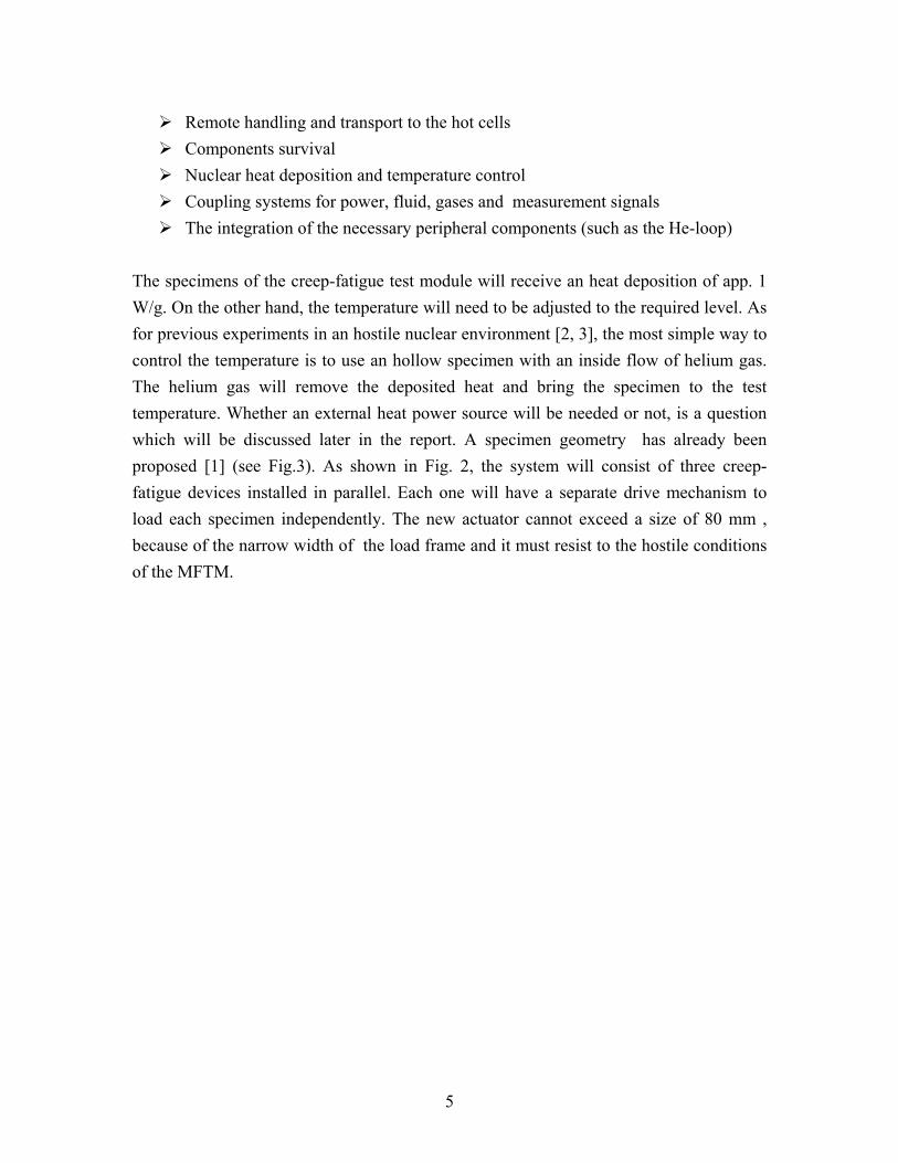
The specimens of the creep-fatigue test module will receive an heat deposition of app. 1 W/g. On the other hand, the temperature will need to be adjusted to the required level. As for previous experiments in an hostile nuclear environment [2, 3], the most simple way to control the temperature is to use an hollow specimen with an inside flow of helium gas. The helium gas will remove the deposited heat and bring the specimen to the test temperature. Whether an external heat power source will be needed or not, is a question which will be discussed later in the report. A specimen geometry has already been proposed [1] (see Fig.3). As shown in Fig. 2, the system will consist of three creep-fatigue devices installed in parallel. Each one will have a separate drive mechanism to load each specimen independently. The new actuator cannot exceed a size of 80 mm , because of the narrow width of the load frame and it must resist to the hostile conditions of the MFTM.
6
Figure 2. The creep-fatigue test module with three fatigue actuators, according to design report [1]

7
Figure 3. Proposed specimen geometry (Dr Möslang)
3. Description of the actuator A technology identical to the one used in the PIREX in situ has been used for the new actuator which consists of a ball screw spindle, an anti-torsion guide, an harmonic drive and an electro-servo motor. The actuator is composed of the following mechanical elements, starting from the left in figure 4:
The electrical motor (1, PARVEX, RS330E) is a direct current, brush equipped, 4 pole servo motor with permanent rare earth magnets and powered with direct current. The motor is equipped with a tachometer generator. At very low rotations per minute the motor can start to turn irregularly, due to the brushes switching to the next pole. This problem will only arise at speeds below 10-15 RPM. Due to the space limitation of VTA2 (80 mm in the beam direction) a better low inertia but bigger size motor cannot be used for our application. The available torque on slow rotation of the RS330E is 0.8 Nm. The nominal voltage applied to the terminals is 90 V at maximal performance, which corresponds to a nominal current of app. 2.7 A. The maximal speed of rotation in normal use is 2200 RPM.
The harmonic drive (2) is a high efficiency, high ratio, zero backlash
8
reduction gear. The principle of operation consists of a wave generator which deforms a thin flexible cylinder with external spline teeth. The flexible cylinder deforms to an ellipse and contacts an outer fixed circular spline on two points. The elliptical inner flexible cylinder turns in relation with the outer spline, but since the flexible spline has two teeth less than the outer spline one revolution of the wave generator creates a relative motion between the inner and outer splines. The flexspline rotates in the opposite direction to the wave generator at a reduction ratio of one half the number of teeth of the flexspline. The reduction ratio of the installed harmonic drive is 1:160.
The ball spindle is mounted on a set of two axial bearings (3) for zero backlash. The radial bearings are pre-loaded axially with a nut to a third of the total load capacity. The ball spindle (4) with a diameter of 20 mm and a pitch of 5mm turns in a twin preloaded ball nuts assembly. The mechanical setup can manage alternating loads without any play. The ball lubrication is done with grease which should be added regularly in relation to the amount of grease lost at the wipers. In normal operation, it is sufficient to add grease every 300 hrs of operation. In the case of IFMIF, due to the radiations which would thicken the grease and increase the friction, dry lubrication will be used.
The anti-torsion ball spline (5) is installed at the extremity of the actuator to take the torque produced at the ball spindle. The ball spline consists of a shaft with three crests positioned equidistantly at 120°and a ball nut with six rows of balls which run on the sides of the crest. There is no angular backlash because the ball rows are preloaded on each side of the crest.
A membrane bellows (6) is mounted at the extremity of the torque shaft to prevent any contamination falling in the area of the specimen and to create a vacuum tight interface.
The available displacement stroke is 25 mm ( 2 x 12.5 mm). The overall mechanical displacement capacity can be increased , if needed up to 32 mm (2 x 16 mm). The system is designed for a nominal force of 25 kN. The system is equipped internally with two limit switches to shut down the power in case of a loss of control. The displacement is measured using a full bridge LVDT having a nominal range amplitude of 25 mm. The LVDT has a very stable time characteristic and normally

9
does not need regular calibrations. The LVDT is mounted permanently inside the actuator body.
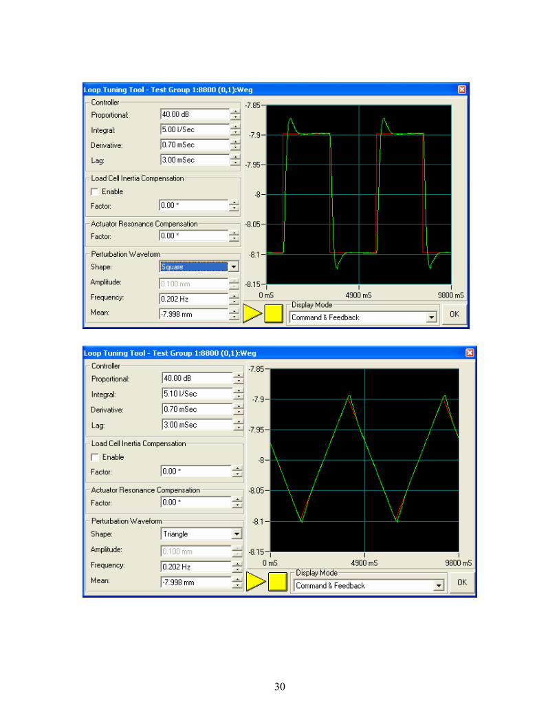
Figure 4. Drawing showing the main mechanical components of the actuator drive mechanism: the electro motor (1), the harmonic drive (2), the axial bearings (3), the ball spindle (4), the ball anti-torque spline (5) and the membrane bellows (6). The mechanical elements are mounted inside an heavy and stable steel body having a cross section of 80 x 100 mm. The overall length of the actuator is of the order of 700 mm. The 80 mm width of the body is at the limits of the space available as described in section 2. Figure 5 shows a 3-D view of the actuator. The actuator was adapted to an electronic INSTRON Fasttrack 8800 equipped with a NORWIN controller. The control response of the unloaded drive is shown in the Annexe. It is interesting to see that the drive is capable of fast responses, responding to a square control signal with a frequency of 0.2 Hz. The drive is also capable of very slow displacements as shown for a triangular command wave with a period of 1000 sec and an amplitude of 0.1 mm. The main characteristics of the drive are given in table 1.
Overall size 80x100x700 mm Weight 34 kg Motor DC motor with brushes Force capacity 25 kN Displacement stroke 25 mm (2 x 12.5 mm) Minimum speed Less than 0.4 microns per second
Table 1. Main characteristics of the actuator

10
Figure 5. Isometrical view of the actuator. The adjustable plate shown on the front face supports the limit switches. The actuator is equipped internally with a displacement measuring device.
4. Experience in PIREX The in situ irradiation device developed at the Paul Scherrer Institute was irradiated with a secondary beam line at the PSI accelerator, in the PIREX II facility. It had the capability of controlling during irradiation the force, the strain and the temperature acting on a fatigue specimen. The main specifications of the system are listed below: • 590 MeV, 20 μA proton beam • Beam density 1-2 μA/mm2 • Helium flow, 100 Nm3/hr, 30 bars • T irradiation 40 to 400 °C • Heat deposition 2-8 kW/cm3 • Heavy transport machinery and hot cell support necessary • Technical innovation: instrumented specimen The system has been used over a period of ten years. The beam history is given in figure 6. During all the experiments ( some 17 experiments with beam) only one load cell was in use. It has been regularly calibrated and never needed to be readjusted. Apparently the load cell was not suffering from the accumulated dose therefore in the following it will be tried to estimate the radiation load and later we will compare it with the one expected in IFMIF. The total beam hours on the in situ target was 1643

11
hours. Figure 7 shows a scheme of the geometrical situation around the specimen. This drawing was used as an input to run calculations with the code MCNPX 2.5.0 to estimate the neutron flux in the PIREX load cell. The load cell was assumed to be mainly of steel, with a mean density of 5.19 g/cm3, based on the external dimensions (882.5 cm3) and weight (3.54 kg). A proton beam of 590 MeV was modelled to hit a tubular iron specimen with an outer diameter of 3.4 mm and inner diameter of 2.7 mm. The neutrons, protons , pions and light ions generated by the spallation reaction were tracked in the geometry shown in Fig. 7 and the cumulated neutron flux was estimated at the location of the load cell.
1993 1994 1995 1996 1997 1998 1999 2000 2001 2002 20030
50
100
150
200
250
300
350
400
Hours on the in situ target
Bea
m ti
me
in h
ours
Year
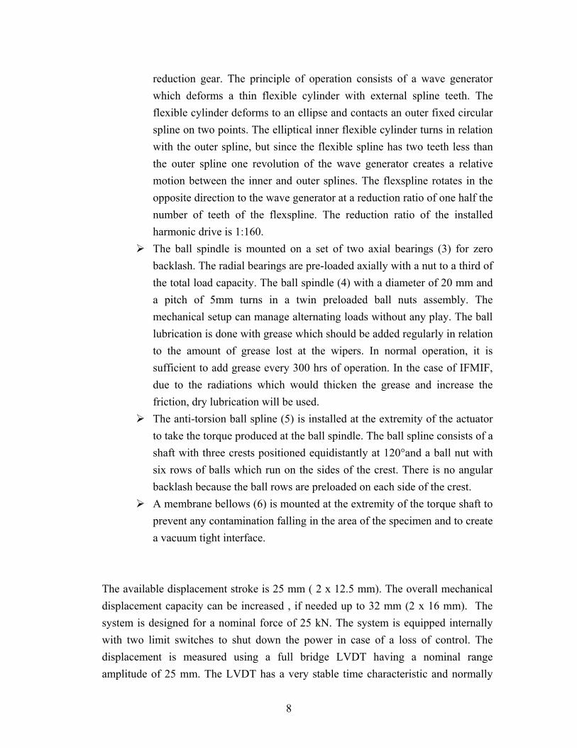
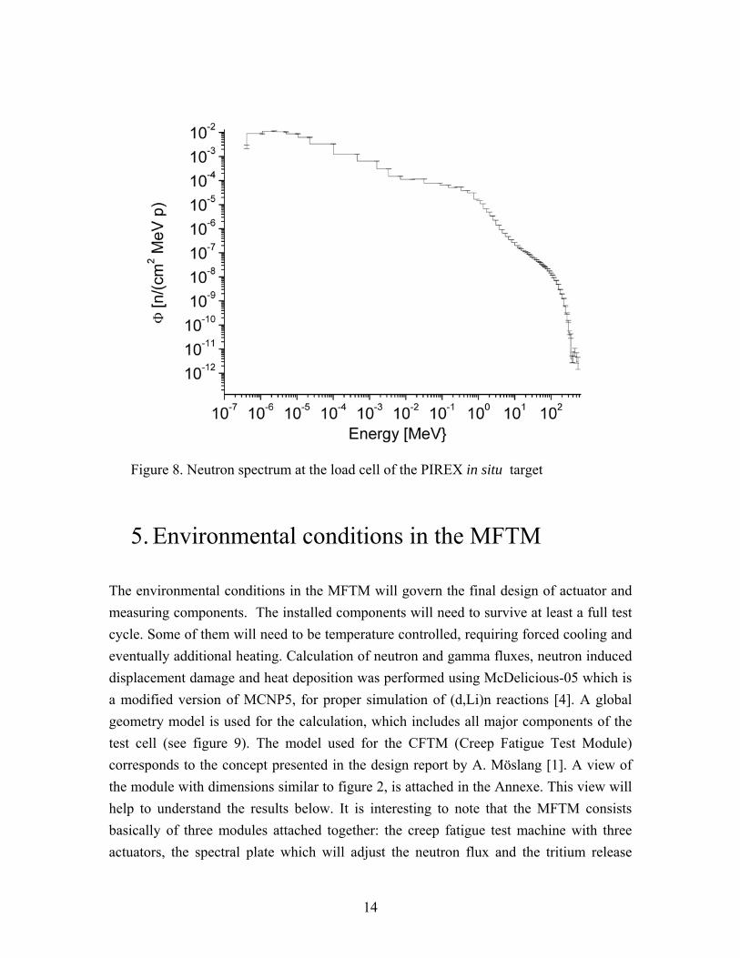
Figure 6. Beam time histogram of the in situ target of PIREX II. The resulting neutron flux per proton in the volume of the load cell is: Φ= 6.131 10-5 n/p cm2 ± 0.12%. The neutron energy spectrum is shown in figure 8. The integration of the energy deposited by this neutron spectrum in the centre of the load cell leads the following value : 9.84135 10-8 MeV/(g p) ± 5.92%. The contribution of the photons is:

12
1.54749 10-6 MeV/(g p) ± 11.46%. The contribution of the protons is: 1.27345 10-6 MeV/(g p) ± 10.27%. The total energy deposited per incident proton is : Ψ= 3.25812 10-6 MeV/(g p) ± 7.27%. The estimation of the neutron fluence and radiation damage is obtained from the total number of protons seen on the target during the life of the system. The mean beam on PIREX was 13 μA. It can be assumed that the beam had a surface of 20 mm2 and that about 30% of the protons were lost because the beam was larger than the specimen.
The mean intensity can be estimated to : 13μA/ 20 mm2x0.7= 0.455 μA/mm2 Which corresponds to : 2.85x10¹⁴ p/cm2s (1 A=6.2414.1018 p/s).
The model did not take into account the beam windows and the cooling tube, therefore the effective irradiation surface is taken at 0.18 cm2. The number of protons crossing the target will be 5.13 1013 p/s. The resulting neutron flux at the load cell is then Φ neutrons = 3.14 109 n/s cm2 The number of protons passing through the target during the total life of the experiment (1643 hours) is: N= 3.034 1020 p The integrated neutron flux on the load cell is then : ΦxN/f = 2.36 1015 n/cm2 (f = 7.88, geometrical factor which takes into account the specimen cross section). The total energy deposited in the load cell will be: ΨxN = 9.885 1014 MeV/g To convert in units relevant for radiation resistance (Gray) we need to express the result into W/g , in the form ΨxN/t, where t is the time of irradiation. The mean power deposited in the load cell is: 9.885 1014 MeV/g x 1.60219 10-13 /1643 3600 s = 0.0268 10-3 W/g With 1 W/g = 1000 Gray/s, the energy deposited is 0.0268 Gray/s This number will be useful to compare with the radiation load acting on the actuator and measuring systems in IFMIF.

13
Figure 7. Geometrical model for the MCNPX calculations. The whole geometry is shown on the left. On the right, the load cell and the specimen in its titanium cooling tube are shown at a larger scale.
14
Figure 8. Neutron spectrum at the load cell of the PIREX in situ target
5. Environmental conditions in the MFTM The environmental conditions in the MFTM will govern the final design of actuator and measuring components. The installed components will need to survive at least a full test cycle. Some of them will need to be temperature controlled, requiring forced cooling and eventually additional heating. Calculation of neutron and gamma fluxes, neutron induced displacement damage and heat deposition was performed using McDelicious-05 which is a modified version of MCNP5, for proper simulation of (d,Li)n reactions [4]. A global geometry model is used for the calculation, which includes all major components of the test cell (see figure 9). The model used for the CFTM (Creep Fatigue Test Module) corresponds to the concept presented in the design report by A. Möslang [1]. A view of the module with dimensions similar to figure 2, is attached in the Annexe. This view will help to understand the results below. It is interesting to note that the MFTM consists basically of three modules attached together: the creep fatigue test machine with three actuators, the spectral plate which will adjust the neutron flux and the tritium release

15
module. The calculations have been performed (all details in document [4]) for the nominal current of 250 mA. The global IFMIF geometry uses the following coordinate system (looking in the direction of beam propagation): z axis goes along the beam direction, x axis is horizontal (left to right) and y axis is vertical but goes downward. Origin in XY plane corresponds to the center of the beam footprint, while Z=0 corresponds to the downstream surface of the target backplate (see Fig. 9). Middle of the central creep-fatigue specimen is located at (0, 0, 9.5 cm). Low Flux Test Module Tritium Release Module Tungsten Spectral Plate MediumFlux Test Module Test Machine Specimens HighFlux Test Module Backplate Figure 9. Horizontal cut trough IFMIF Test Cell
5.1 Neutron fluxes
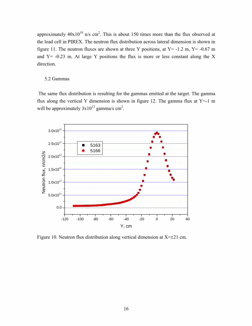
Spatial distribution of neutron flux in the frame of the creep fatigue test module along vertical direction is shown in figure 10. The frame is located to the sides of the three actuators. The values indicated in figure 10 are given at the location X=±21 cm. It can be seen from the figure that the flux 1 meter above the beam axis reaches a value of
16
approximately 40x1010 n/s cm2. This is about 150 times more than the flux observed at the load cell in PIREX. The neutron flux distribution across lateral dimension is shown in figure 11. The neutron fluxes are shown at three Y positions, at Y= -1.2 m, Y= -0.67 m and Y= -0.23 m. At large Y positions the flux is more or less constant along the X direction.
5.2 Gammas
The same flux distribution is resulting for the gammas emitted at the target. The gamma flux along the vertical Y dimension is shown in figure 12. The gamma flux at Y=-1 m will be approximately 3x10¹² gamma/s cm2.
-120 -100 -80 -60 -40 -20 0 20 40
0.0
5.0x10¹¹
1.0x10¹²
1.5x10¹²
2.0x10¹²
2.5x10¹²
3.0x10¹²
Neu
tron
flux,
n/c
m2/
s
Y, cm
5163 5166
Figure 10. Neutron flux distribution along vertical dimension at X=±21 cm.

17
-20 -15 -10 -5 0 5 10 15 207x1010
8x10109x1010
1011
1012
2x10¹²
3x10¹²N
eutro
n Fl
ux, n
/cm
2 /s
X, cm
5161 5160 5129 5060 5000
Figure 11. Neutron fluxes along X direction at Y= -1.2 m (5160,5161), Y= -0.67 m (5129) and Y= -0.23 m (5060,5000).
-120 -100 -80 -60 -40 -20 0 20 40
0.0
5.0x10¹²
1.0x10¹³
1.5x10¹³
2.0x10¹³
Gam
ma
flux,
gam
ma/
cm2/
s
Y, cm
5163 5166
Figure 12. Gamma flux distribution along vertical dimension at X=±21 cm.
18
5.3 Damage rates
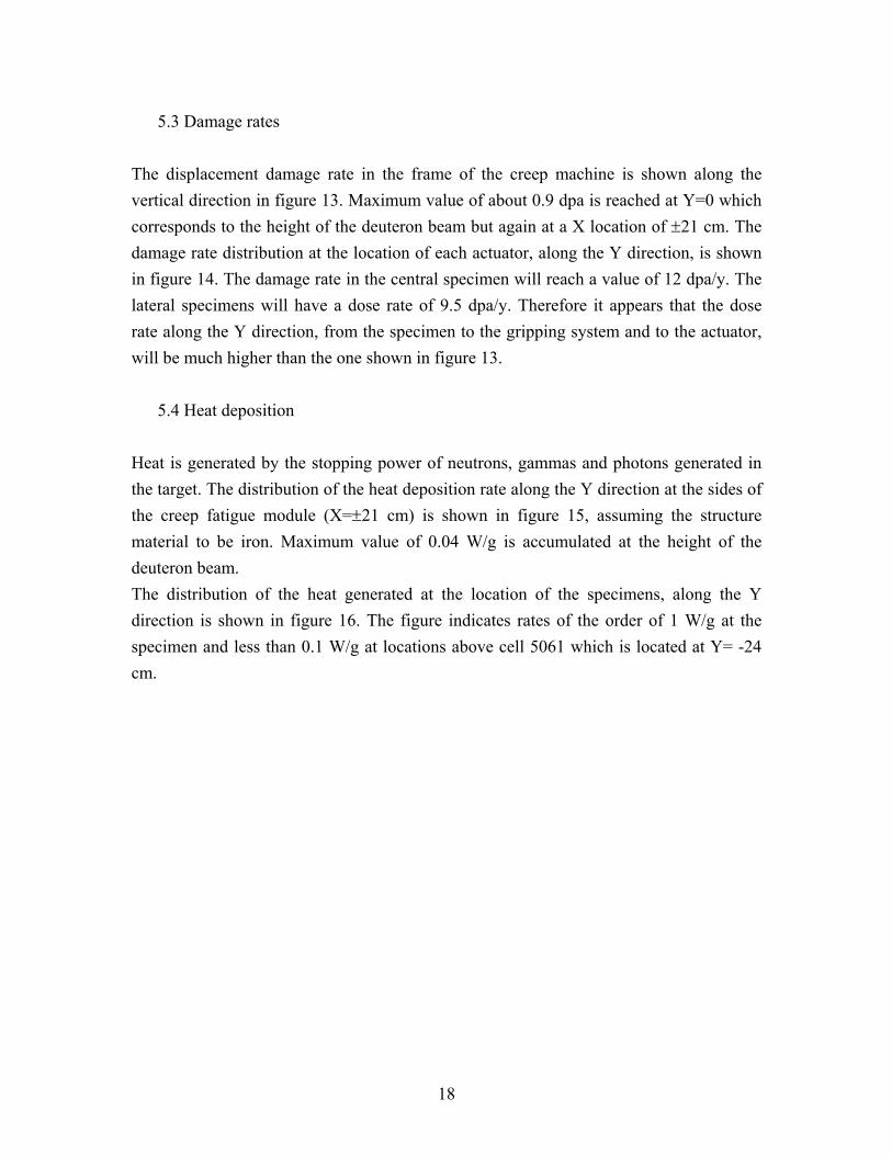
The displacement damage rate in the frame of the creep machine is shown along the vertical direction in figure 13. Maximum value of about 0.9 dpa is reached at Y=0 which corresponds to the height of the deuteron beam but again at a X location of ±21 cm. The damage rate distribution at the location of each actuator, along the Y direction, is shown in figure 14. The damage rate in the central specimen will reach a value of 12 dpa/y. The lateral specimens will have a dose rate of 9.5 dpa/y. Therefore it appears that the dose rate along the Y direction, from the specimen to the gripping system and to the actuator, will be much higher than the one shown in figure 13.
5.4 Heat deposition
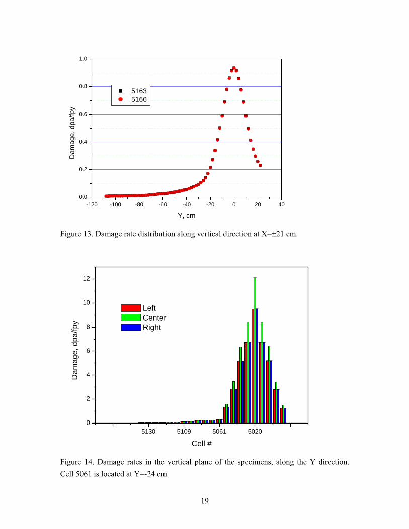
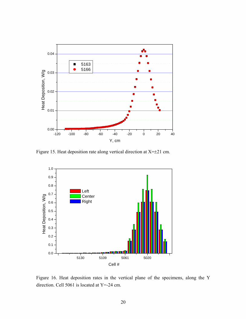
Heat is generated by the stopping power of neutrons, gammas and photons generated in the target. The distribution of the heat deposition rate along the Y direction at the sides of the creep fatigue module (X=±21 cm) is shown in figure 15, assuming the structure material to be iron. Maximum value of 0.04 W/g is accumulated at the height of the deuteron beam. The distribution of the heat generated at the location of the specimens, along the Y direction is shown in figure 16. The figure indicates rates of the order of 1 W/g at the specimen and less than 0.1 W/g at locations above cell 5061 which is located at Y= -24 cm.
19
-120 -100 -80 -60 -40 -20 0 20 400.0
0.2
0.4
0.6
0.8
1.0
Dam
age,
dpa
/fpy
Y, cm
5163 5166
Figure 13. Damage rate distribution along vertical direction at X=±21 cm.
5130 5109 5061 50200
2
4
6
8
10
12
Left Center Right
Dam
age,
dpa
/fpy
Cell #
Figure 14. Damage rates in the vertical plane of the specimens, along the Y direction. Cell 5061 is located at Y=-24 cm.
20
-120 -100 -80 -60 -40 -20 0 20 400.00
0.01
0.02
0.03
0.04
Hea
t Dep
ositi
on, W
/g
Y, cm
5163 5166
Figure 15. Heat deposition rate along vertical direction at X=±21 cm.
5130 5109 5061 50200.0
0.1
0.2
0.3
0.4
0.5
0.6
0.7
0.8
0.9
1.0
Left Center Right
Hea
t Dep
ositi
on, W
/g
Cell #
Figure 16. Heat deposition rates in the vertical plane of the specimens, along the Y direction. Cell 5061 is located at Y=-24 cm.
21
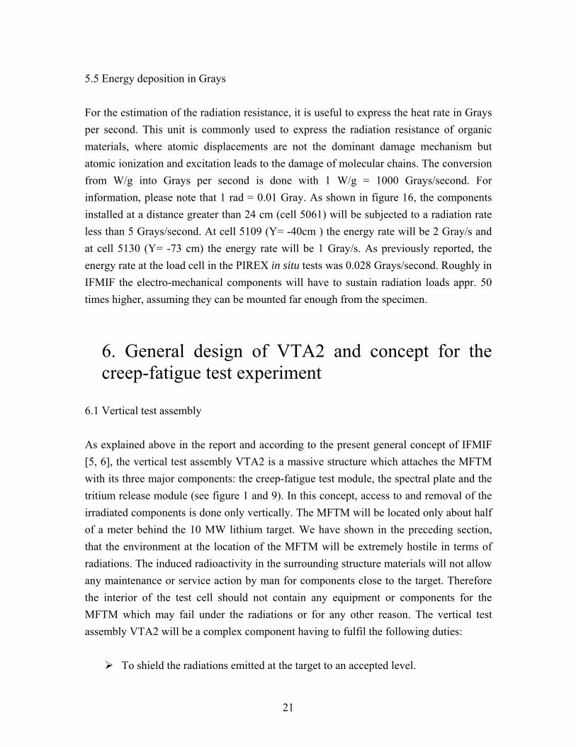
5.5 Energy deposition in Grays For the estimation of the radiation resistance, it is useful to express the heat rate in Grays per second. This unit is commonly used to express the radiation resistance of organic materials, where atomic displacements are not the dominant damage mechanism but atomic ionization and excitation leads to the damage of molecular chains. The conversion from W/g into Grays per second is done with 1 W/g = 1000 Grays/second. For information, please note that 1 rad = 0.01 Gray. As shown in figure 16, the components installed at a distance greater than 24 cm (cell 5061) will be subjected to a radiation rate less than 5 Grays/second. At cell 5109 (Y= -40cm ) the energy rate will be 2 Gray/s and at cell 5130 (Y= -73 cm) the energy rate will be 1 Gray/s. As previously reported, the energy rate at the load cell in the PIREX in situ tests was 0.028 Grays/second. Roughly in IFMIF the electro-mechanical components will have to sustain radiation loads appr. 50 times higher, assuming they can be mounted far enough from the specimen.
6. General design of VTA2 and concept for the creep-fatigue test experiment
6.1 Vertical test assembly As explained above in the report and according to the present general concept of IFMIF [5, 6], the vertical test assembly VTA2 is a massive structure which attaches the MFTM with its three major components: the creep-fatigue test module, the spectral plate and the tritium release module (see figure 1 and 9). In this concept, access to and removal of the irradiated components is done only vertically. The MFTM will be located only about half of a meter behind the 10 MW lithium target. We have shown in the preceding section, that the environment at the location of the MFTM will be extremely hostile in terms of radiations. The induced radioactivity in the surrounding structure materials will not allow any maintenance or service action by man for components close to the target. Therefore the interior of the test cell should not contain any equipment or components for the MFTM which may fail under the radiations or for any other reason. The vertical test assembly VTA2 will be a complex component having to fulfil the following duties:
To shield the radiations emitted at the target to an accepted level.

22
To deliver electrical and measuring signals, gaseous and power lines to the MFTM.
To carry the three MFTM modules. To position accurately the MFTM in the test cell and to remove the MFTM from
the test cell. To transport the MFTM to a place (access cell to remote handling cells) where it
can be separated and delivered to the hot cells, where the service actions for the operation of the different modules can be done.
To satisfy the requirements above it seems necessary to equip the VTA2 with two automatic coupling units, one situated at the top of VTA2 and which would be easily remotely operated from the control room of the access cell. This first coupling system would serve to connect automatically all lines necessary for the operation of the three modules as well as to connect the pipes necessary for the cooling of the vertical assembly itself. The second coupling unit could be installed in the middle of the VTA2 and should have the following two functions, first to attach mechanically the MFTM to the VTA2 and second to connect and disconnect remotely the instrumentation and cooling lines of the three modules of the MFTM. Figure 17 presents schematically a view of the VTA2 with the position of the two interfaces.
Figure 17. View of the VTA2 plug with the MFTM at the bottom and the two interfaces where coupling units will need to be installed.

23
6.2 MFTM The MFTM will consist of three modules which will be dedicated to specific research experiments pertinent for the design of the DEMO reactor. In this respect, the design of the MFTM should be flexible to take into account the possibility of installing unforeseen modules. For instance, presently the Japanese side is proposing the installation of other experiments in the MFTM, a crack growth experiment and a model of the DEMO blanket. For this reason the middle interface VTA2-MFTM will have the capability to attach independently three modules, each one having a given width. Eventually the modules will need to be interchangeable with the consequence that the coupling system will need three sub-interfaces equipped with the same amount of electrical, power and gas connectors. Once the MFTM is inserted in the hot cell, the modules will be disconnected by manipulators. Again this work should be fast and reliable, therefore the interface will need to incorporate specially designed coupling mechanism to ensure simple operation by manipulators. The hot cell dedicated for this work will need to be very large as each module will have a size of approximately 1 by 2 meters. 6.3 Creep-fatigue test module (CFTM) The creep-fatigue test module will consist of a coupling frame on which three independent test sub-modules will be mounted. Each sub-module will be a fully instrumented test machine. Due to the very intense radiation environment, no attempt will be done to change a specimen but a fully prepared unirradiated system will be installed for every test. Each sub-module will have his own loading frame in the form of three vertical columns. Furthermore the specimen will be directly integrated in the system, so to avoid complicated gripping procedures. This philosophy has the advantage of limiting the dose accumulation in the electromechanical components as well as the possibility of precisely adjusting the strain measuring system before the test. A further advantage will be the increased reliability due to the absence of a specimen seal change in the hot cell. In the contrary the whole instrumented system will be installed onto the interface frame using a coupling mechanism. The load cell will be a critical component due to the intense radiation fields. For this reason it will be installed as far as possible from the beam axis and will need some shielding. A good place is in the interior of the actuator. For this, the trolley acting on the

24
anti-torsion shaft will be modified to incorporate the load cell. Another component critical under radiations is the displacement transducer. This component is already placed in the actuator. To further protect both components some extra shielding materials (graphite for the neutrons and high density metal for the gammas) will be installed in the body of the actuator, if possible. Finally the system will need a fine strain extensometer, to measure the strain onto the gauge length of the specimen. This primary component will first rely on a classical mechanical design. Two ceramic bars will be applied onto the gauge length and their displacement transferred axially to a set of radiation resistant LVDT’s placed at a sufficient distance. Another design based on waves will be developed as a backup. The problem of the radiation resistance of components and the heat generated and temperature control are discussed in more details in the two following sections. 6.3.1 Radiation resistance The actuator presented in section 3 represents the most delicate and demanding part of the system. The actuator will generate the mechanical wave needed for the creep-fatigue experiment. It is equipped with radiation sensitive components: the load cell, the displacement transducer, the limit switches and the electromotor. The duration of the experiment will at least correspond to the shortest operating cycle of IFMIF. We have shown in section 5 that electro-mechanical components installed at a distance of about 70 cm above the deuteron beam axis will receive radiation energies (neutrons and gammas) of the order of 1 Gray/sec. For a full cycle of IFMIF (8.4 months of operation corresponding to 70% availability) the dose could easily reach 21 MGy. Depending on the material, polymers are significantly affected by radiations at doses between 1 kGy to 1 Mgy [7, 8]. In the annexe, two tables from reference [7] are reproduced which give the dose to reduce the elongation by 25% for the most common polymers irradiated at air. Unfortunately available data only reach up to 1.5 MGy. Nevertheless the tables indicates that acetals, polypropylene, neoprene and PTFE should be avoided. Polystyrenes and polyimides (trademark Kapton, for instance) seem to be the best materials. It is also important to note that polymers are more affected by the irradiation under the presence of air, since oxygen reacts with the chemical chains and increases the number of molecular scissions. A load cell will need to be developed for the actuator. It will incorporate many strain gages. A strain gage consists of a metallic grid deposited onto an organic substrate. The gage is usually glued on the surface of the transducer with epoxy resin. Information about

25
the radiation resistance of strain gages was found in an internal report of the company Measurements Group [9]. Some of the information has been summarized in table 2. The metallic grid of the gage is suffering from an increase in electrical resistivity. Depending on how the gages are electrically connected to each other, this change may have only a minor influence. More problematic is the change of the gage factor (the overall electrical sensivity under strain) under irradiation. Changes of the order of 10 to 15% have been reported in [9], whereas the corresponding neutron dose is not clearly given. This change would be proportional to dose with the result that any transducer built from strain gages will have a calibration factor proportional to dose. Obviously the calibration of the load cell will need to be checked as a function of the dose expected during IFMIF experiments. According to report [9], transducers using conventional strain gages of polyimide and epoxy bonded element can withstand gamma exposures up to 109 ergs/g which corresponds to 0.1 MGy (100 ergs/g = 10-2 Grays). The numbers indicated in table 2 are generally one order of magnitude lower than the expected dose in IFMIF (Y=-70cm). This is a clear indication that the load cell will need some additional shielding. To measure the displacement of the actuator shaft, an inductive transducer LVDT (Linear Voltage Differential Transducer) will be used. Transducers specially developed for reactor environment are available. The radiation resistance of those devices should be sufficient for the environment of IFMIF [10]. If used close to the specimen where polymers cannot survive, special all metal cables with aluminium oxide insulation are available. Material Exposed Dose of Gamma Radiation Effect of Exposure
1 MGy Safe operation limit Open face constantan grids 4 MGy Possibility of gage failure
Epoxy as a substrate 4 MGy Safe operation limit Polyimide as a substrate 1000 MGy No physical degradation M-Bond 600-610 adhesive 6 MGy Upper limit Teflon as insulator 0.2 MGy Possibility of cracks PVC as insulator 6 MGy Upper limit Sn/Pb as solder 0.2 MGy Upper limit Table 2. Effect of radiation on the constituents of strain gages
26
6.3.2 Heat removal and specimen temperature control system One difficult challenge in the design of the CFTM will be the control of the temperature. At the moment, the experimental temperature window has not yet been defined but for the first design attempt, a temperature range between 150°C and 450°C should be a first goal for the design. Due to the presence of lithium in the target, the only coolant available is helium gas which will be provided by one or many gas loops. Due to the very limited space available, an electric helium heater with heat recuperation can not be considered. To reach high operating temperatures, the radiations themselves will be used as the main heat power source. As shown in Fig.15 and 16, the heat rate for the steel parts in the specimen area will be around 1 W/g. The heat generated is roughly proportional to the material density. Taking a high density material like tungsten (ρ=19.25 g/cm3), heat generation rates of 2.4 W/g will be reached. Heat generating bodies, eventually radially isolated will be designed to transfer the heat power axially by conduction to the grips holding the specimen. For each operating temperature, the specimen area will need a specific design. The creep fatigue experiments have to be run at a constant temperature. The mean temperature should not vary by more than 10°C. The requirement for the temperature gradients within the gauge length of the specimen are even more severe: there the temperature should not vary by more than 5 degrees. A temperature control system will compensate for variations of the radiation fluxes induced by changes at the accelerator. The radiation power may decrease, in this case an electrical heater close to the specimen will generate heat which will reach the specimen area by conduction. In the case of radiation power increase, helium gas flowing in channels close to the specimen will extract the additional gamma heating. A thermo hydraulic study will decide if the specimen will be a solid specimen heated and cooled by heat conduction or whether it should be an hollow specimen with internal gas flow. If the temperature gradient requirement and the lower range of the temperature window can be achieved with the solid specimen, of course this specimen would be the best candidate since most fatigue studies available in open literature are produced from solid specimens. On the other hand, for certification purposes, requirements published in standards usually apply for solid specimens. The actuator, placed approximately 50 cm above the beam axis, will be heated by the gammas at a rate of approximately 0.025 W/g. With a mass of 35 kg, the actuator will generate approximately 1 kW. Therefore cooling channels will need to be placed in the

27
actuator body for heat removal. Other components placed close to the CFTM will also generate heat and influence the temperature of the specimen. The high flux irradiation rig (see Fig. 1 and 9, lower part of the High Flux Test Module) is installed a few cm ahead of the specimens and will generate heat back to the specimen area. The neutron spectral plate is placed behind the specimens (Fig.9) and will also produce heat towards the specimens. Probably an exact prediction of the operating temperature will require some computer simulations with an overall geometrical model.
7. Further recommendations Actuator: As shown in section 3, a drive has been developed according to the specifications of IFMIF and partially tested. The drive still needs to demonstrate its force capability and behaviour under load. The system needs to be tested in the future into a series of real fatigue tests in order to simulate the testing conditions in IFMIF. For this it will be necessary to build a fatigue set up with extensometer. It will also be useful to conduct the tests at temperature and under vacuum, in order to conduct useful tests. These tests will also have to be run with the updated version of the actuator, equipped with the integrated load cell. For this purpose a vacuum furnace will be designed to incorporate the drive. A figure of the projected fatigue set-up is shown in the annexe. In particular, these tests could be used to validate the definitive IFMIF specimen geometry. An extensive series of tests should be conducted and compared with results published in the literature Reactor irradiations: To qualify the CFTM for safe operation in IFMIF, the load cell, the displacement transducer and extensometers, will need to be tested in a reactor irradiation, under neutrons and gammas. The components should be irradiated in different stages after which the calibration of the components should be checked in order to follow up any changes in the characteristics of the devices.
8. Summary and main conclusions
In this report we have developed a general concept for the design of the medium flux

28
test area, based on the general design of IFMIF. The system consists of a vertical test assembly which carries three test modules, a creep fatigue test module, a spectral neutron plate and a tritium release module. The vertical assembly inserts the three modules into the target and shields the radiations. The vertical assembly removes the test modules and bring them in the test cell where they are separated and transported to the service hot cells. This concept requires two interfaces with automatic couplings, the first at the top of the vertical assembly and the second in the middle of it, for separation of the modules. The modules need also to be disconnected independently. The creep fatigue test module consists of three independent test machines. Each test machine is composed of a mechanical actuator, a gripping system to hold the specimen and a measuring system. The actuator is the heart of the machine. A prototype fitting the dimensions of the IFMIF target has been designed and successfully tested. Due to the hostile environment, the test machine will be used only once. We have shown in the report that the electro-mechanical components would not survive much more than a year and the preparation of a fully instrumented test machine is easier in the unirradiated condition. The temperature control system will use gamma heating as the main power source, helium gas flow and electric heating as regulating means.
References:
1. Möslang, A., Development of a Reference Test Matrix for IFMIF Test Modules. 2006, Forschungszentrum Karlsruhe, Institut für Materialforschung I. p. 1-34.
2. Marmy, P., et al., PIREX II- A new irradiation facility for testing fusion first wall materials. Nuclear Instruments and Methods in Physics Research, 1990. B47: p. 37-47.
3. Möslang, A., et al., In-situ fatigue experiments on the Karlsruhe Dual Beam Facility: Capabilities and first Results. Fusion Technology, 1992: p. 1439-1443.
4. Vladimirov, P., A. Möslang, and P. Marmy, Nuclear responses in the creep-fatigue testing machine. Fusion Engineering and Design, 2007. XXX: p. YYY, ZZZ.
5. IFMIF Comprehensive Design Report. 2004, The International Energy Agency. 6. Heinzel, V., et al. Helium cooled high and medium flux test modules for the
international fusion material irradiation facility. in 21st IEEE/NPSS Symposium on Fusion Engineering (SOFE). 2005. Knoxville.
7. Hemmerich, K.J., Polymer Materials Selection for Radiation-Sterilized Products. Medical Device and Diagnostic Industry, 2000. 22(PART 2): p. 78-89.

29
8. Laghari, J.R. and A.N. Hammoud, A brief survey of radiation effects on polymer dielectrics. IEEE Transactions on Nuclear Science, 1990. 37(No. 2): p. 1076-1082.
9. JD, Radiation Resistance of Strain Gages. 1994, Measurements Group Vishay. p. 1-6.
10. Johnsen, T. and K.W. Eriksen, Transducers for irradiation environment in the Halden reactor. 2005: Private communication.
ANNEXE
Figure A-1: Series of five diagrams showing the dynamic response of the actuator under fast and slow command signals (red curve).
Figure A-2: Front view of the Creep Fatigue Test Module with main
dimensions Figure A-3: View showing how the actuator will be fitted to a vacuum furnace to conduct extensive fatigue tests under conditions relevant for IFMIF Figure A-4: Dose (0-500 kgrays) at which a polymer experiences an
elongation decrease of 25% (irradiations at air). Figure A-5: Dose (0-1500 kgrays) at which a polymer experiences an
elongation decrease of 25% (irradiations at air).
30

31
32
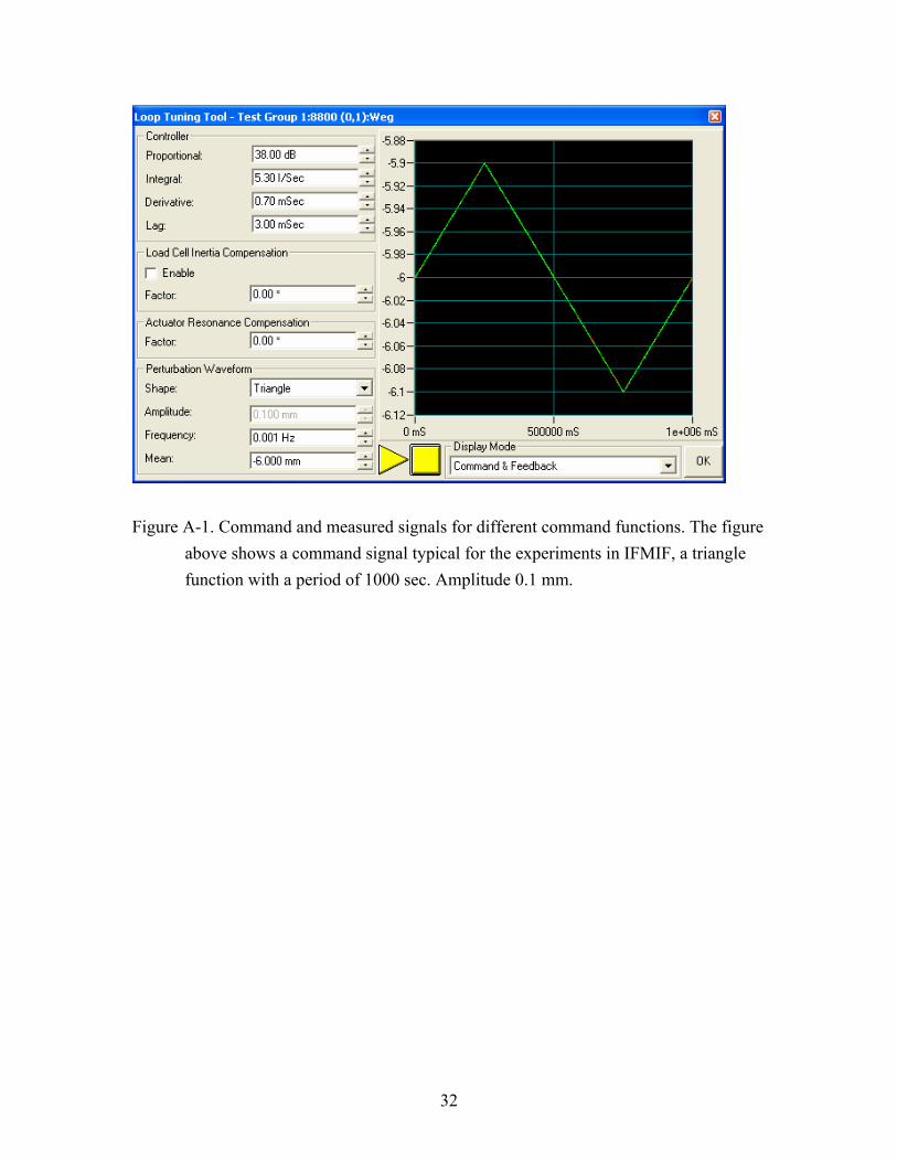
Figure A-1. Command and measured signals for different command functions. The figure
above shows a command signal typical for the experiments in IFMIF, a triangle function with a period of 1000 sec. Amplitude 0.1 mm.

33
FIGURE A-2: CREEP FATIGUE TEST MODULE WITH DIMENSIONS (from Report IMF-I 074/IRS04/05/Fusion 246)

34
Figure A-3: View showing how the actuator will be fitted to a vacuum furnace to conduct extensive fatigue tests under conditions relevant for IFMIF

35
Figure A-4: Dose to reduce elongation by 25%, from Hemmerich, K.J., Polymer Materials Selection for Radiation-Sterilized Products. Medical Device and Diagnostic Industry, 2000. 22

36
Figure A-5: From Hemmerich, K.J., Polymer Materials Selection for Radiation-Sterilized Products. Medical Device and Diagnostic Industry, 2000. 22