ifu 5909098 fixed beam anchor - 3m · pdf fileadjustable beam hook fixed beam hook adjustment...
TRANSCRIPT
© Copyright 2014, Capital Safety
The Ultimate in Fall Protection
User Instruction ManualFixed Beam Anchor
This manual is intended to meet the Manufacturer’s Instructions as required by ANSI Z359.1 and should be used as part of an employee
training program as required by OSHA.
Instructions for the following series products:
FIXED BEAM ANCHOR
Model Numbers:
2108406 2108407 21084082108409 2108410 2108411
Form: 5909098 Rev: G

3
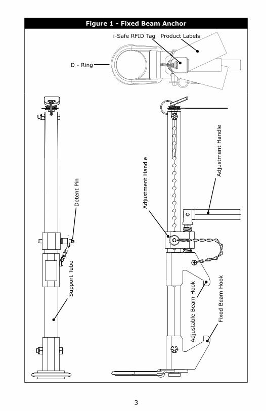
Figure 1 - Fixed Beam Anchor
D - Ring
Product Labelsi-Safe RFID Tag
Det
ent
Pin
Sup
port
Tub
e
Adj
usta
ble
Bea
m H
ook
Fixe
d Bea
m H
ook
Adj
ustm
ent
Han
dle
Adj
ustm
ent
Han
dle
4
WARNING: This product is part of a personal fall protection system. The user must read and follow the manufacturer’s instructions for each component of the system. These instructions must be provided to the user and the rescuer. (See section 8 Terminology.) The user must read and understand these instructions before using this equipment. Manufacturer’s instructions must be followed for proper use and maintenance of this equipment. Alterations or misuse of this equipment, or failure to follow instructions, may result in serious injury or death.
IMPORTANT: If you have questions on the use, care, or suitability of this equipment for your application, contact DBI-SALA.
IMPORTANT: Record the product identifi cation information from the ID label in the “Inspection and Maintenance Log”.
DESCRIPTION
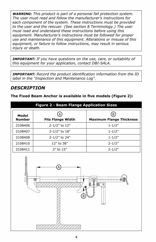
The Fixed Beam Anchor is available in fi ve models (Figure 2):
Figure 2 - Beam Flange Application Sizes
Model Number
AFits Flange Width
BMaximum Flange Thickness
2108406 2-1/2” to 12” 1-1/2”
2108407 2-1/2” to 18” 1-1/2”
2108408 2-1/2” to 24” 1-1/2”
2108410 12” to 36” 2-1/2”
2108411 3” to 15” 2-1/2”
A
B
5
1.0 APPLICATIONS
1.1 PURPOSE: The Fixed Beam Anchor is an anchorage connector for a personal fall arrest system, designed to be attached to a beam. The Fixed Beam Anchor may be used as an end termination for DBI-SALA approved horizontal lifeline systems.
1.2 LIMITATIONS: The following application limitations must be considered before using this equipment:
A. BEAM FLANGE SIZES: The Fixed Beam Anchor may only be installed on beams with flanges within the adjustment range of the model. See Figure 2.
B. CAPACITY: This equipment is designed for use by persons with a combined weight (clothing, tools, etc.) of no more than 310 lbs. No more than one personal protective system may be connected to this equipment at one time. When this equipment is used as an end termination for a horizontal lifeline the maximum capacity is 2,500 lbs.
C. PERSONAL FALL ARREST SYSTEM: The personal fall arrest system used with this equipment must meet the requirements specified in section 2.1.
D. FREE FALL: Personal fall arrest systems used with this equipment must be rigged to limit the free fall to a maximum of six feet when possible, as required by OSHA. The maximum free fall must always be within the manufacturer’s free fall capacity of the system components used to arrest the fall. See section 2.1 and connecting subsystem manufacturer’s instructions for more information.
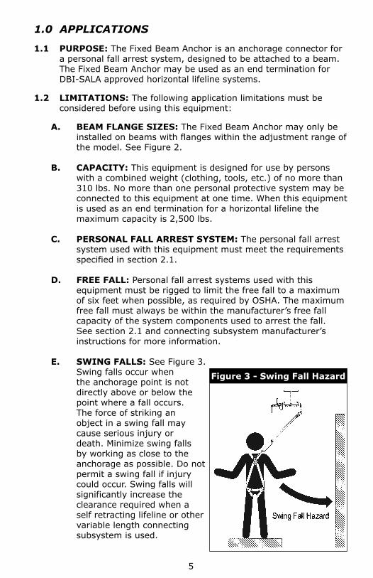
E. SWING FALLS: See Figure 3. Swing falls occur when the anchorage point is not directly above or below the point where a fall occurs. The force of striking an object in a swing fall may cause serious injury or death. Minimize swing falls by working as close to the anchorage as possible. Do not permit a swing fall if injury could occur. Swing falls will significantly increase the clearance required when a self retracting lifeline or other variable length connecting subsystem is used.
Figure 3 - Swing Fall Hazard
6
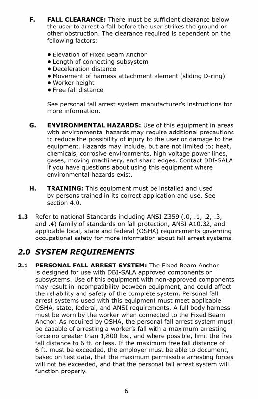
F. FALL CLEARANCE: There must be sufficient clearance below the user to arrest a fall before the user strikes the ground or other obstruction. The clearance required is dependent on the following factors:
• Elevation of Fixed Beam Anchor • Length of connecting subsystem • Deceleration distance • Movement of harness attachment element (sliding D-ring) • Worker height • Free fall distance
See personal fall arrest system manufacturer’s instructions for more information.
G. ENVIRONMENTAL HAZARDS: Use of this equipment in areas with environmental hazards may require additional precautions to reduce the possibility of injury to the user or damage to the equipment. Hazards may include, but are not limited to; heat, chemicals, corrosive environments, high voltage power lines, gases, moving machinery, and sharp edges. Contact DBI-SALA if you have questions about using this equipment where environmental hazards exist.
H. TRAINING: This equipment must be installed and used by persons trained in its correct application and use. See section 4.0.
1.3 Refer to national Standards including ANSI Z359 (.0, .1, .2, .3, and .4) family of standards on fall protection, ANSI A10.32, and applicable local, state and federal (OSHA) requirements governing occupational safety for more information about fall arrest systems.
2.0 SYSTEM REQUIREMENTS
2.1 PERSONAL FALL ARREST SYSTEM: The Fixed Beam Anchor is designed for use with DBI-SALA approved components or subsystems. Use of this equipment with non-approved components may result in incompatibility between equipment, and could affect the reliability and safety of the complete system. Personal fall arrest systems used with this equipment must meet applicable OSHA, state, federal, and ANSI requirements. A full body harness must be worn by the worker when connected to the Fixed Beam Anchor. As required by OSHA, the personal fall arrest system must be capable of arresting a worker’s fall with a maximum arresting force no greater than 1,800 lbs., and where possible, limit the free fall distance to 6 ft. or less. If the maximum free fall distance of 6 ft. must be exceeded, the employer must be able to document, based on test data, that the maximum permissible arresting forces will not be exceeded, and that the personal fall arrest system will function properly.
7
When a free fall greater than 6 ft. and up to a maximum of 12 ft. is possible, DBI-SALA recommends using a personal fall arrest system incorporating a DBI-SALA Force2 energy absorbing lanyard. DBI-SALA has performed testing using the Force2 energy absorbing lanyard in free falls up to twelve feet to ensure the maximum arresting force does not exceed 1,800 lbs., and the system functions properly. The results of these tests are listed in the user instruction manual provided with Force2 shock absorbing lanyards.
2.2 COMPATIBILITY OF COMPONENTS: DBI-SALA equipment is designed for use with DBI-SALA approved components and subsystems only. Substitutions or replacements made with non-approved components or subsystems may jeopardize compatibility of equipment and may effect the safety and reliability of the complete system.
2.3 COMPATIBILITY OF CONNECTORS: Connectors are considered to be compatible with connecting elements when they have been designed to work together in such a way that their sizes and shapes do not cause their gate mechanisms to inadvertently open regardless of how they become oriented. Contact DBI-SALA if you have any questions about compatibility.
Connectors ( hooks, carabiners, and D-rings) must be capable of supporting at least 5,000 lbs. (22.2kN). Connectors must be compatible with the anchorage or other system components. Do not use equipment that is not compatible. Non-compatible connectors may unintentionally disengage. See Figure 4. Connectors must be compatible in size, shape, and strength. Self locking snap hooks and carabiners are required by ANSI Z359.1 and OSHA.
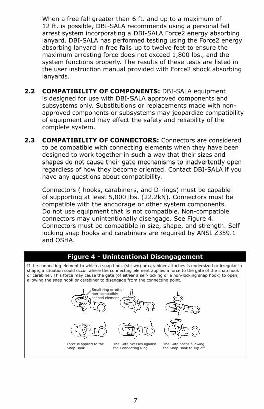
Figure 4 - Unintentional DisengagementIf the connecting element to which a snap hook (shown) or carabiner attaches is undersized or irregular in shape, a situation could occur where the connecting element applies a force to the gate of the snap hook or carabiner. This force may cause the gate (of either a self-locking or a non-locking snap hook) to open, allowing the snap hook or carabiner to disengage from the connecting point.
Small ring or other non-compatibly shaped element
Force is applied to the Snap Hook.
The Gate presses against the Connecting Ring.
The Gate opens allowing the Snap Hook to slip off.
8
2.4 MAKING CONNECTIONS: Only use self-locking snap hooks and carabiners with this equipment. Only use connectors that are suitable to each application. Ensure all connections are compatible in size, shape and strength. Do not use equipment that is not compatible. Ensure all connectors are fully closed and locked.
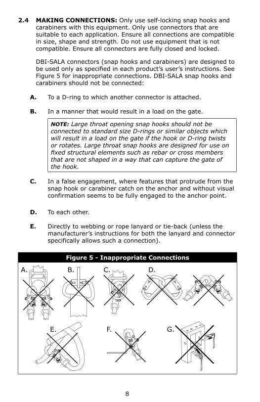
DBI-SALA connectors (snap hooks and carabiners) are designed to be used only as specifi ed in each product’s user’s instructions. See Figure 5 for inappropriate connections. DBI-SALA snap hooks and carabiners should not be connected:
A. To a D-ring to which another connector is attached.
B. In a manner that would result in a load on the gate.
NOTE: Large throat opening snap hooks should not be connected to standard size D-rings or similar objects which will result in a load on the gate if the hook or D-ring twists or rotates. Large throat snap hooks are designed for use on fi xed structural elements such as rebar or cross members that are not shaped in a way that can capture the gate of the hook.
C. In a false engagement, where features that protrude from the snap hook or carabiner catch on the anchor and without visual confirmation seems to be fully engaged to the anchor point.
D. To each other.
E. Directly to webbing or rope lanyard or tie-back (unless the manufacturer’s instructions for both the lanyard and connector specifically allows such a connection).
Figure 5 - Inappropriate Connections
A. B. C. D.
E. F. G.
9
F. To any object which is shaped or dimensioned such that the snap hook or carabiner will not close and lock, or that roll-out could occur.
G. In a manner that does not allow the connector to align properly while under load.
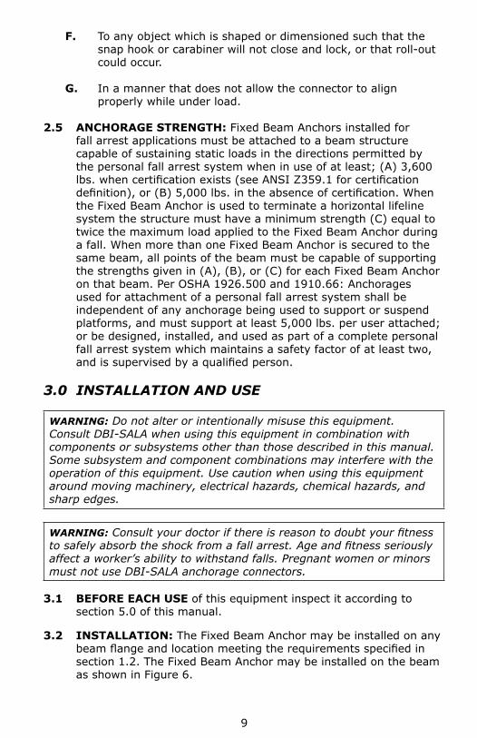
2.5 ANCHORAGE STRENGTH: Fixed Beam Anchors installed for fall arrest applications must be attached to a beam structure capable of sustaining static loads in the directions permitted by the personal fall arrest system when in use of at least; (A) 3,600 lbs. when certifi cation exists (see ANSI Z359.1 for certifi cation defi nition), or (B) 5,000 lbs. in the absence of certifi cation. When the Fixed Beam Anchor is used to terminate a horizontal lifeline system the structure must have a minimum strength (C) equal to twice the maximum load applied to the Fixed Beam Anchor during a fall. When more than one Fixed Beam Anchor is secured to the same beam, all points of the beam must be capable of supporting the strengths given in (A), (B), or (C) for each Fixed Beam Anchor on that beam. Per OSHA 1926.500 and 1910.66: Anchorages used for attachment of a personal fall arrest system shall be independent of any anchorage being used to support or suspend platforms, and must support at least 5,000 lbs. per user attached; or be designed, installed, and used as part of a complete personal fall arrest system which maintains a safety factor of at least two, and is supervised by a qualifi ed person.
3.0 INSTALLATION AND USE
WARNING: Do not alter or intentionally misuse this equipment. Consult DBI-SALA when using this equipment in combination with components or subsystems other than those described in this manual. Some subsystem and component combinations may interfere with the operation of this equipment. Use caution when using this equipment around moving machinery, electrical hazards, chemical hazards, and sharp edges.
WARNING: Consult your doctor if there is reason to doubt your fi tness to safely absorb the shock from a fall arrest. Age and fi tness seriously affect a worker’s ability to withstand falls. Pregnant women or minors must not use DBI-SALA anchorage connectors.
3.1 BEFORE EACH USE of this equipment inspect it according to section 5.0 of this manual.
3.2 INSTALLATION: The Fixed Beam Anchor may be installed on any beam fl ange and location meeting the requirements specifi ed in section 1.2. The Fixed Beam Anchor may be installed on the beam as shown in Figure 6.
10
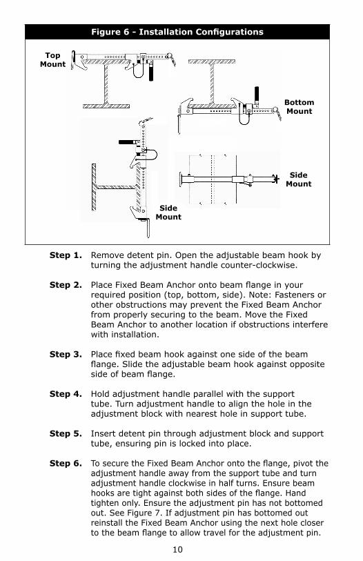
Figure 6 - Installation Confi gurations
TopMount
BottomMount
SideMount
SideMount
Step 1. Remove detent pin. Open the adjustable beam hook by turning the adjustment handle counter-clockwise.
Step 2. Place Fixed Beam Anchor onto beam fl ange in your required position (top, bottom, side). Note: Fasteners or other obstructions may prevent the Fixed Beam Anchor from properly securing to the beam. Move the Fixed Beam Anchor to another location if obstructions interfere with installation.
Step 3. Place fi xed beam hook against one side of the beam fl ange. Slide the adjustable beam hook against opposite side of beam fl ange.
Step 4. Hold adjustment handle parallel with the support tube. Turn adjustment handle to align the hole in the adjustment block with nearest hole in support tube.
Step 5. Insert detent pin through adjustment block and support tube, ensuring pin is locked into place.
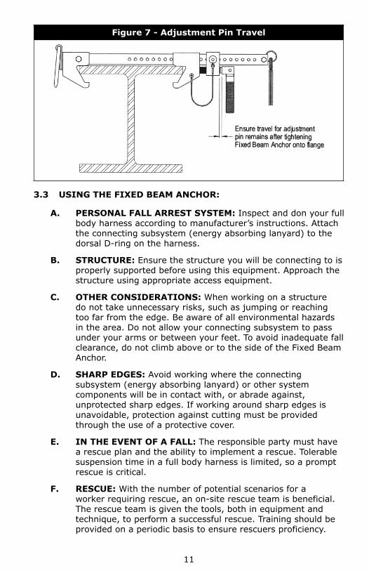
Step 6. To secure the Fixed Beam Anchor onto the fl ange, pivot the adjustment handle away from the support tube and turn adjustment handle clockwise in half turns. Ensure beam hooks are tight against both sides of the fl ange. Hand tighten only. Ensure the adjustment pin has not bottomed out. See Figure 7. If adjustment pin has bottomed out reinstall the Fixed Beam Anchor using the next hole closer to the beam fl ange to allow travel for the adjustment pin.
11
Figure 7 - Adjustment Pin Travel
3.3 USING THE FIXED BEAM ANCHOR:
A. PERSONAL FALL ARREST SYSTEM: Inspect and don your full body harness according to manufacturer’s instructions. Attach the connecting subsystem (energy absorbing lanyard) to the dorsal D-ring on the harness.
B. STRUCTURE: Ensure the structure you will be connecting to is properly supported before using this equipment. Approach the structure using appropriate access equipment.
C. OTHER CONSIDERATIONS: When working on a structure do not take unnecessary risks, such as jumping or reaching too far from the edge. Be aware of all environmental hazards in the area. Do not allow your connecting subsystem to pass under your arms or between your feet. To avoid inadequate fall clearance, do not climb above or to the side of the Fixed Beam Anchor.
D. SHARP EDGES: Avoid working where the connecting subsystem (energy absorbing lanyard) or other system components will be in contact with, or abrade against, unprotected sharp edges. If working around sharp edges is unavoidable, protection against cutting must be provided through the use of a protective cover.
E. IN THE EVENT OF A FALL: The responsible party must have a rescue plan and the ability to implement a rescue. Tolerable suspension time in a full body harness is limited, so a prompt rescue is critical.
F. RESCUE: With the number of potential scenarios for a worker requiring rescue, an on-site rescue team is beneficial. The rescue team is given the tools, both in equipment and technique, to perform a successful rescue. Training should be provided on a periodic basis to ensure rescuers proficiency.
12
4.0 TRAINING
4.1 It is the responsibility of the user to assure they are familiar with these instructions, and are trained in the correct care and use of this equipment. User must also be aware of the operating characteristics, application limits, and the consequences of improper use of this equipment.
5.0 INSPECTION
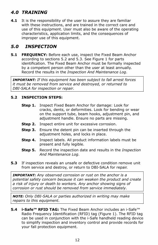
5.1 FREQUENCY: Before each use, inspect the Fixed Beam Anchor according to sections 5.2 and 5.3. See Figure 1 for parts identifi cation. The Fixed Beam Anchor must be formally inspected by a competent person other than the user at least annually. Record the results in the Inspection And Maintenance Log.
IMPORTANT: If this equipment has been subject to fall arrest forces it must be removed from service and destroyed, or returned to DBI-SALA for inspection or repair.
5.2 INSPECTION STEPS:
Step 1. Inspect Fixed Beam Anchor for damage: Look for cracks, dents, or deformities. Look for bending or wear on the support tube, beam hooks, adjustment pin, and adjustment handle. Ensure no parts are missing.
Step 2. Inspect entire unit for excessive corrosion.Step 3. Ensure the detent pin can be inserted through the
adjustment holes, and locks in place.Step 4. Inspect labels. All product information labels must be
present and fully legible.Step 5. Record the inspection date and results in the Inspection
And Maintenance Log.
5.3 If inspection reveals an unsafe or defective condition remove unit from service and destroy, or return to DBI-SALA for repair.
IMPORTANT: Any observed corrosion or rust on the anchor is a potential safety concern because it can weaken the product and create a risk of injury or death to workers. Any anchor showing signs of corrosion or rust should be removed from service immediately.
NOTE: Only DBI-SALA or parties authorized in writing may make repairs to this equipment.
5.4 i-Safe™ RFID TAG: The Fixed Beam Anchor includes an i-Safe™ Radio Frequency Identifi cation (RFID) tag (Figure 1). The RFID tag can be used in conjunction with the i-Safe handheld reading device to simplify inspection and inventory control and provide records for your fall protection equipment.
13
6.0 MAINTENANCE, SERVICING, STORAGE
6.1 CLEANING: Periodically clean the Fixed Beam Anchor using water and a mild soap solution. Do not use acids or other caustic chemicals that could damage the system components. A lubricant may be applied to the detent pin.
6.2 USER EQUIPMENT: Maintain, service, and store harness and personal fall arrest components according to manufacturer’s instructions.
7.0 SPECIFICATIONS
7.1 MATERIALS: All materials used in the construction of this equipment are as
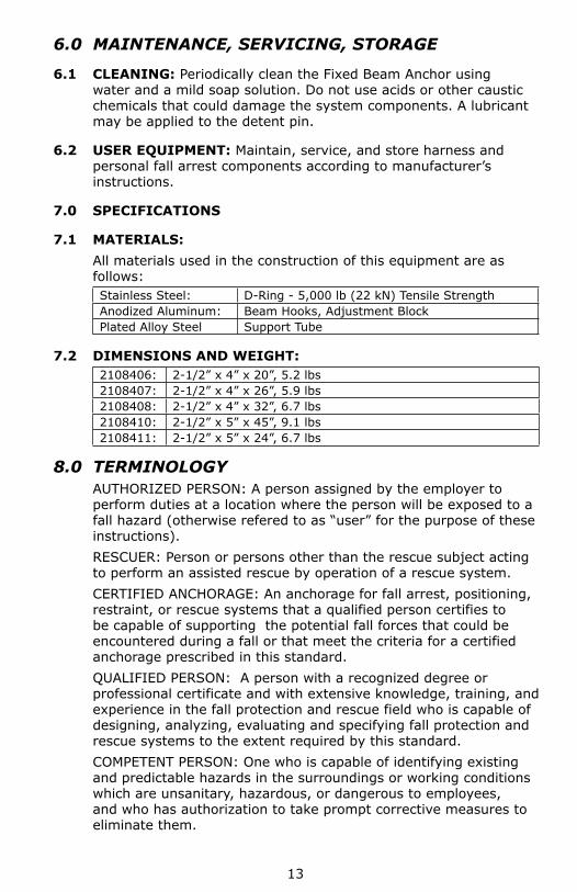
follows:Stainless Steel: D-Ring - 5,000 lb (22 kN) Tensile StrengthAnodized Aluminum: Beam Hooks, Adjustment BlockPlated Alloy Steel Support Tube
7.2 DIMENSIONS AND WEIGHT:2108406: 2-1/2” x 4” x 20”, 5.2 lbs2108407: 2-1/2” x 4” x 26”, 5.9 lbs2108408: 2-1/2” x 4” x 32”, 6.7 lbs2108410: 2-1/2” x 5” x 45”, 9.1 lbs2108411: 2-1/2” x 5” x 24”, 6.7 lbs
8.0 TERMINOLOGYAUTHORIZED PERSON: A person assigned by the employer to perform duties at a location where the person will be exposed to a fall hazard (otherwise refered to as “user” for the purpose of these instructions).RESCUER: Person or persons other than the rescue subject acting to perform an assisted rescue by operation of a rescue system.CERTIFIED ANCHORAGE: An anchorage for fall arrest, positioning, restraint, or rescue systems that a qualified person certifies to be capable of supporting the potential fall forces that could be encountered during a fall or that meet the criteria for a certified anchorage prescribed in this standard.QUALIFIED PERSON: A person with a recognized degree or professional certificate and with extensive knowledge, training, and experience in the fall protection and rescue field who is capable of designing, analyzing, evaluating and specifying fall protection and rescue systems to the extent required by this standard.COMPETENT PERSON: One who is capable of identifying existing and predictable hazards in the surroundings or working conditions which are unsanitary, hazardous, or dangerous to employees, and who has authorization to take prompt corrective measures to eliminate them.
14
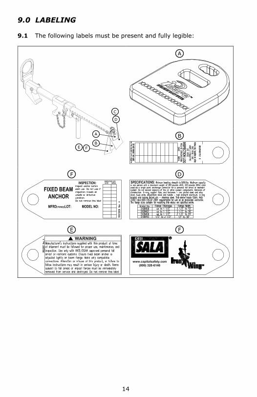
9.0 LABELING
9.1 The following labels must be present and fully legible:
A
D
C
BFE
A
B
F D
E F
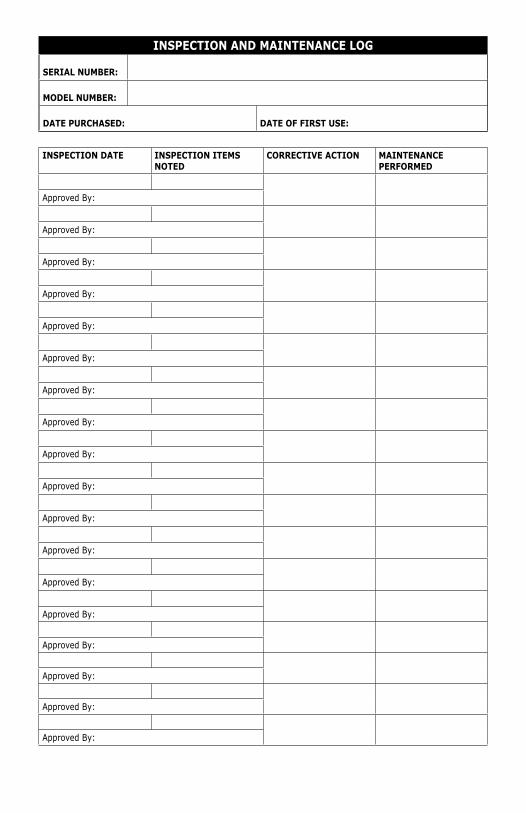
INSPECTION AND MAINTENANCE LOG
SERIAL NUMBER:
MODEL NUMBER:
DATE PURCHASED: DATE OF FIRST USE:
INSPECTION DATE INSPECTION ITEMS NOTED
CORRECTIVE ACTION MAINTENANCE PERFORMED
Approved By:
Approved By:
Approved By:
Approved By:
Approved By:
Approved By:
Approved By:
Approved By:
Approved By:
Approved By:
Approved By:
Approved By:
Approved By:
Approved By:
Approved By:
Approved By:
Approved By:
Approved By:
LIMITED LIFETIME WARRANTY
Warranty to End User: D B Industries, Inc., dba CAPITAL SAFETY USA (“CAPITAL SAFETY”) warrants to the original end user (“End User”) that its products are free from defects in materials and workmanship under normal use and service. This warranty extends for the lifetime of the product from the date the product is purchased by the End User, in new and unused condition, from a CAPITAL SAFETY authorized distributor. CAPITAL SAFETY’S entire liability to End User and End User’s exclusive remedy under this warranty is limited to the repair or replacement in kind of any defective product within its lifetime (as CAPITAL SAFETY in its sole discretion determines and deems appropriate). No oral or written information or advice given by CAPITAL SAFETY, its distributors, directors, offi cers, agents or employees shall create any different or additional warranties or in any way increase the scope of this warranty. CAPITAL SAFETY will not accept liability for defects that are the result of product abuse, misuse, alteration or modifi cation, or for defects that are due to a failure to install, maintain, or use the product in accordance with the manufacturer’s instructions.
CAPITAL SAFETY’S WARRANTY APPLIES ONLY TO THE END USER. THIS WARRANTY IS THE ONLY WARRANTY APPLICABLE TO OUR PRODUCTS AND IS IN LIEU OF ALL OTHER WARRANTIES AND LIABILITIES, EXPRESSED OR IMPLIED. CAPITAL SAFETY EXPRESSLY EXCLUDES AND DISCLAIMS ANY IMPLIED WARRANTIES OF MERCHANTABILITY OR FITNESS FOR A PARTICULAR PURPOSE, AND SHALL NOT BE LIABLE FOR INCIDENTAL, PUNITIVE OR CONSEQUENTIAL DAMAGES OF ANY NATURE, INCLUDING WITHOUT LIMITATION, LOST PROFITS, REVENUES, OR PRODUCTIVITY, OR FOR BODILY INJURY OR DEATH OR LOSS OR DAMAGE TO PROPERTY, UNDER ANY THEORY OF LIABILITY, INCLUDING WITHOUT LIMITATION, CONTRACT, WARRANTY, STRICT LIABILITY, TORT (INCLUDING NEGLIGENCE) OR OTHER LEGAL OR EQUITABLE THEORY.
I S O9001
CSG USA & Latin America3833 SALA Way Red Wing, MN 55066-5005 Toll Free: 800.328.6146Phone: 651.388.8282Fax: [email protected]
CSG Canada260 Export Boulevard Mississauga, ON L5S 1Y9 Phone: 905.795.9333 Toll-Free: 800.387.7484 Fax: 888.387.7484 [email protected]
CSG Northern Europe5a Merse RoadNorth Moons, MoatReditch, Worcestershire, UKB98 9HLPhone: + 44 (0)1527 548 000Fax: + 44 (0)1527 591 [email protected]
CSG EMEA(Europe, Middle East, Africa)Le Broc CenterZ.I. 1ère Avenue5600 M B.P. 15 06511CarrosLe Broc CedexFrancePhone: + 33 4 97 10 00 10Fax: + 33 4 93 08 79 [email protected]
CSG Australia & New Zealand95 Derby StreetSilverwaterSydney NSW 2128AUSTRALIAPhone: +(61) 2 8753 7600Toll-Free : 1 800 245 002 (AUS)Toll-Free : 0800 212 505 (NZ) Fax: +(61) 2 87853 7603 [email protected]
CSG AsiaSingapore:16S, Enterprise Road Singapore 627666Phone: +65 - 65587758Fax: +65 - [email protected]
Shanghai:Rm 1406, China Venturetech Plaza819 Nan Jing Xi Rd,Shanghai 200041, P R ChinaPhone: +86 21 62539050Fax: +86 21 62539060
www.capitalsafety.com
The Ultimate in Fall Protection