igbt driver mtc-3073 - dutt · the driver mtc-3073 has different gate resistors rgate personalized...
TRANSCRIPT

DRIVER IGBT 3073
1/5 DRIVER 3073 v0 english Revisión: 28/07/2015
Driver for double IGBTs of mid-range, in a 1200-1700V working range. This driver by itself can control a branch (TOP and BOTTOM)
This card, unlike another type of Driver is personalized from factory. Does not need additional elements such as printed circuits, resistors, capacitors, neither calculations, nor adjustments, just input control signals and the IGBT connections. (collector, emitter and gate).
Each Driver is adjusted to be able to operate only with one or two IGBT modules. With this personalization a better performance is obtained and there is a better adaptation to electric and physical characteristics of each IGBT.
Easy connections from the board to the IGBT through faston terminals. Connections with interface through double 16PIN row.
4500V (Up.eff.) electric insulation between primary and secondary. 4500V (Up.eff.) electric insulation between secondaries. Inputs TOP, BOTTOM and INH (inputs CMOS 20V max., 3K3 impedance). Inputs signals filtration. Signals with less time than 1µs are rejected. Trigger inputs protected against electrostatic discharges. Min. dead time generation, can not be accumulated to the one applied by software. Working cycle from 0 to 100%. Recommended tension for boards supply 16 VDC. Protection against supply drop in voltage in both secondaries +13V/-13V. Protections against overcurrents by comparison of the Vce.sat. with prefixed standard. Soft shut down of the IGBT with alarm. (This procedure avoids Vce overtension in the most
unfavourable moment). Overcurrent active protection on the switching off of the IGBT “DVRC” (Dynamic Voltage
Rise Control). This protections acts from 900V on. Configurated according to model. Open-Collector output alarm. Alarm prolonged during 30ms. Signals and supply connexion through double pins row. Working temperature from –40ºC to 70ºC Commutation frequency 20 KHz Possibility of higher frequencies up to 60 Khz for other IGBTs families. Measurements 67x116mm. Trigger with +15V/-15V in both IGBTs Easy adaptation with interface MTC-3074.
DESCRIPTION
SPECIFICATIONS
DRIVER IGBT 3073
2/5 DRIVER 3073 v0 english Revisión: 28/07/2015
Explanatory notes:
All inputs are protected against tension peaks. The INH input is an additional input for input pulses authorization, when it is not used it will have to
remain as +Vcc.
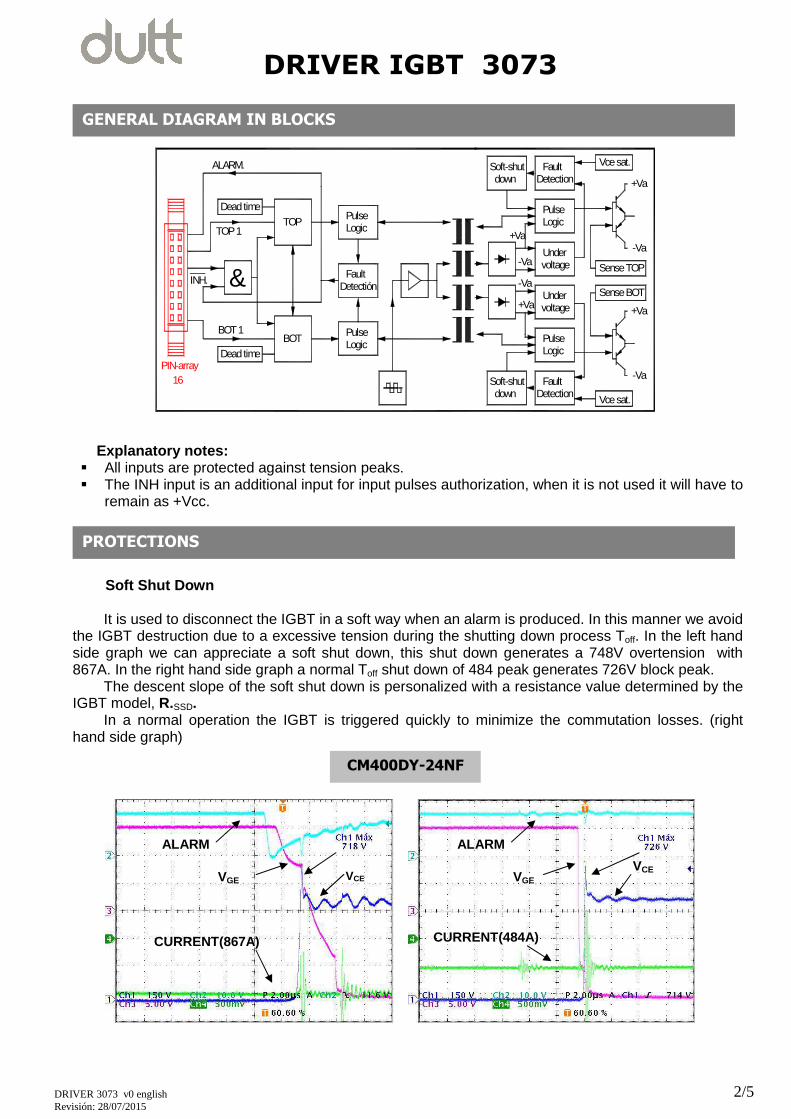
Soft Shut Down
It is used to disconnect the IGBT in a soft way when an alarm is produced. In this manner we avoid
the IGBT destruction due to a excessive tension during the shutting down process Toff. In the left hand side graph we can appreciate a soft shut down, this shut down generates a 748V overtension with 867A. In the right hand side graph a normal Toff shut down of 484 peak generates 726V block peak.
The descent slope of the soft shut down is personalized with a resistance value determined by the IGBT model, R.SSD.
In a normal operation the IGBT is triggered quickly to minimize the commutation losses. (right hand side graph)
PROTECTIONS
&
16PIN-array
ALARM.
INH.
BOT 1
TOP 1
-Va
+Va
Soft-shutdown
Undervoltage
LogicPulse
DetectionFault
Sense BOT
Vce sat.
+Va
-Va
Sense TOP-Va
+Va-Va
+Va
voltageUnder
Soft-shutdown
Vce sat.FaultDetection
PulseLogic
FaultDetectión
LogicPulseBOT
Dead time
Dead timeTOP Logic
Pulse
GENERAL DIAGRAM IN BLOCKS
VGE
CURRENT(484A)
ALARM
VCE
ALARM
VGE
CURRENT(867A)
VCE
CM400DY-24NF

DRIVER IGBT 3073
3/5 DRIVER 3073 v0 english Revisión: 28/07/2015
The protection circuit is based on comparing constantly the Vce.sat with a prearranged standard, if
for any reason, the Vce.sat exceeds the standard, a soft shut down takes places. This MTC-3073 Driver is personalized to each IGBT with different Vce.sat comparison standards, depending on “Vce.sat
lecture retard”, ”Switching on” and “Vce.sat” according to “Characteristics table” attached at the end of the document.
The driver is adjusted to be able to operate with just one or two IGBT modules. Each driver is personalized to each IGBTs electric characteristics, in this manner a better performance is obtained and there is a better adaptation to electric and physique characteristics of each IGBT.
Power supply secondary alarm.
If the secondary supply falls because a short-circuit or an excessive consumption, a trigger in bad conditions or insufficient can be originated, being able to destroy the IGBT. To prevent this situation there is a comparator in each of the secondaries that cuts the triggers when the power supply falls below +13/-13V.
This alarm also generates a “Soft Shut Down”.
Active alarm “DVRC” (Dynamic Voltage Rise Control). In the normal working cycle of the IGBT exists the possibility that the short-circuit takes place exactly during the normal shut down Toff (rapid shut down) of the IGBT, this is a very strange case, but it can happen. In this case the system will not realize a soft shut down, being able to destroy the IGBT. For these cases, the “DVRC” active alarm is implanted. This additional circuit controls the derivative di/dt in all the IGBT shutting down operation, therefore prevents an inadmissible Vce voltage. In the graph below we can see how the protection has entered from 900V of Vce.
Dead time guarantees us the minimum commutation time between triggers in a branch, before one
starts driving the other must be shut down. This dead time is assured by hardware. This time can not be accumulated to the one that could be added by software. If the control generates a time lower than the one stipulated to the equipment, the circuit adds this minimum dead time.
4µs is this drivers dead time.
DEAD TIME
VGE VCE
CM400DY-24NF

DRIVER IGBT 3073
4/5 DRIVER 3073 v0 english Revisión: 28/07/2015
Each of the channels (top y bottom) has a filter on the input that filters all signals lower than 1µs . This passive filter that we have connected to the input guarantees the elimination of any not wanted electric noise.
The driver MTC-3073 has different gate resistors Rgate personalized to each IGBT according to
“Characteristics table” attached at the end of the document. The Rgate resistor is adapted searching the ideal working point of the IGBT, trying to obtain a
better performance of the equipment, as well as a better protection.
DRIVER CONNECTION
INPUTS SIGNALS FILTER TOP/BOTTOM
GATE RESISTOR Rgate
Supply connection and signals to exterior through double pins row. This row is placed on card reverse.
Connection on to IGBT through faston terminals, in “Base G1-2” and the “Emisor E1-2” from (TOP and BOTTOM) and through cable “Colector C1” fromTOP
C 1
E 1,C 2
E 2
G 2
G 1
T O P
B O T T O M
DRIVER CARD INTERFACE
CONNECTION INTERFACE

DRIVER IGBT 3073
5/5 DRIVER 3073 v0 english Revisión: 28/07/2015
CARD MODEL CODE
Lecture Retard Vce.
Ton tail value IGBT
Vce. Sat.
R. SSD. Value
DVRC. V.
Rg. DRIVE
(Ω)
Rg. mod. IGBT (Ω)
Qg IGBT (nC).
NF LINE SERIE A
MTC-3073- 202 650ns 390pf 2,35 2k 900 1,6 3 1350 CM200DY-24NF CM300DY-24A MTC-3073- 402 760ns 470pf 2,35 2k 900 0,73 2 2700 CM400DY-24NF CM600DY-24A
* MTC-3073- 207 760ns 470pf 2,65 2k 1200 2,4 1330 CM200DY-34A
* MTC-3073- 407 900ns 470pf 2,65 2k 1200 1,6 2000 CM300DY-34A * Preliminaries
PIN OUT
Pin Signal Remark
1 +VDD 15-16V
2 +VDD 3 GND Ground 0V 4 TOP
PWM Input TOP 5 TOP 6 GND Ground 0V 7 BOT
PWM Input BOT 8 BOT 9 GND Ground 0V 10 INH Input INH.
0 = Stop 11 INH 12 GND Ground 0V 13 reserved.
14 reserved. 15 ALARM.
Fault Output 16 ALARM.
16
14
12
10
8
6
4
15
13
11
9
7
5
3
CHARACTERISTICS TABLE