ignition of gases by two successive sparks with reference...
TRANSCRIPT

COMBUSTION AND FLAME 27, 85-98 (1976) 85
Ignition of Gases by Two Successive Sparks with Reference to
Frequency Effect of Capacitance Sparks
MICHIKATA KONO, SEIICHIRO KUMAGAI and TADAMI SAKAI Department of Aeronautics, Faculty of Engineering,
University of Takyo, Bunkyo-ku, Tokyo, Japan
The fact that the igniting ability of a capacitance spark increases as the frequency of an oscillatory discharge decreases has been previously ascertained down to about 260 kHz. The present study was undertaken to investigate how matters stand at lower frequencies. In the experiments using lean propane-air mixtures, the igniting ability of a capacitance spark is found to reach a maximum at a frequency of about 100 kHz. In order to elucidate the mechanism of such a frequency effect, two successive sparks of very short duration, which pass across the gap at a controllable time interval, are used as substitutes for halves of the first cycle of an oscillatory discharge. The experimental results show that the igniting ability of two successive sparks is highest at an interval of 10 to 50/~sec, which corresponds to a frequency of 50 to 10 kHz for the oscillatory discharge. This fact suggests that the discharge frequency rather than the spark duration is the predominant factor in ignition by a capacitance spark. A simplified thermal theory taking into consideration the shape and behavior of a spark kernel is given to explain the effect of frequency on the igniting ability of capacitance sparks.
1. Introduction In the ignition of gases by sparks, it is well known that the igniting ability of a capacitance spark increases as increasing inductance is in- corporated in series in the spark-discharge cir- cuit [I, 2, 3]. This phenomenon has not been studied systematically except for the previous experiment by Finch and Thompson [1], in which they stated that the discharge frequency is a predominant factor in establishing ignition and they ascertained that the igniting ability of a capacitance spark increases with increasing inductance and hence decreasing frequency down to about 260 kHz.
This explanation of the above-mentioned experiment was contested, however, by Lewis and yon Elbe [4]. They suggested that the in- crease in the igniting ability due to the increase in inductance, namely the decrease in fre- quency, is caused by the reduction of the quenching effect of the spark electrodes, which indeed may arise from the increase of induc- tance according to their provis ional in-
terpretation. Moreover, Blanc et al. [5] men- tioned that the discharge frequency appears to have no appreciable effect on a minimum igni- tion energy which is determined experimen- tally.
In order to clarify the mechanism of such phenomena, the present study investigates how matters stand at a discharge frequency lower than 260 kHz. As described later, the igniting ability of a capacitance spark is found to reach a maximum over a certain range of frequency. For elucidation of the frequency effect, a spark of very short duration is substi- tuted for each half of the first cycle of an oscil- latory discharge, and experiments on ignition by two such successive sparks are performed.
2. Frequency Effects in Ignition by Capacitance Sparks 2.1 Apparatus and Procedure
The osci l latory capaci tance spark is ob- tained by the conventional method; a capacitor is gradually charged through a high resistance
Copyright © 1976 by The Combustion Institute Published by American Elsevier Publishing Company, Inc.

86 M. KONO, S. KUMAGAI, AND T. SAKAI
from a Wimshurs t influence machine until a discharge through an inductance coil occurs to p r o d u c e a s ingle s p a r k in a c o m b u s t i o n c h a m b e r . The c y l i n d r i c a l c o m b u s t i o n chamber , 30 m m in diameter and 35 mm in length, is provided with glass windows for schlieren-photographic observat ion. After the c o m b u s t i o n c h a m b e r is filled with a lean propane-air mixture, it is connected to the at- mosphere by use of a small s topcock to achieve a constant -pressure combust ion. At a given experimental condition, 25 to 30 spark dis- charges are observed and ignition is recorded; thus, the percentage of ignition for its condition is obtained.
Spark electrodes are located at the center of the combust ion chamber . The gap width can be adjusted accurately by means of a built-in mic- rometer . The end of each electrode is fitted with a spherical steel ball, 2 mm in diameter , for the p u r p o s e of k e e p i n g a c o n s t a n t b reakdown-vol tage for a known gap width. Values of the breakdown-vol tage obtained in air are shown in Table l together with the cor- responding stored energy. These values are much the same as those obtained in fuel-air gaseous mixtures.
TABLE 1 Breakdown-Voltage of Spark and Stored Energy
Gap Breakdown Stored Capacitance width voltage energy
(pF) (mm) (kV) (m J)
90 1.5 6.0 1.6 90 2.0 6.8 2.1 90 3.0 7.8 2.7
455 1.5 6.0 8.2 455 2.0 6.8 10.5 455 3.0 7.8 13.8
Two capaci tors of 90 and 455 pF each are combined with four air-cored inductors cover- ing the range f rom 34 / zH to 144 m H to give discharge frequencies in the range of about 20 kHz to 3 MHz. The voltage and current traces, which are observab le on a dua l -beam syn- chroscope, show that the discharges are essen- tially identical with the well-known oscillatory arc d ischarge except that they are damped os- cillations. The voltage traces indicate that the
residual energy in the capaci tor is negligibly small as compared with the stored energy. Therefore, the energy released at the spark gap is equal to the stored energy minus the lost energy which corresponds to the Joule ' s heat in the series resistance. The lost energy, as calcu- lated from the current traces, are shown in Fig. 1 as a percentage of the stored energy. The measurements represented by the broken lines were carried out under conditions such that the internal resistance was the only air-cored in- ductor included in the discharge circuit.
In Fig. 2 the f requency and spark duration, obtained f rom the voltage traces, are shown as a function of the inductance. As seen f rom this figure, the f requency can be expressed as
1 f - - - - (1 )
2n x/~C
where f , L and C denote the f requency, induc- tance and capaci tance, respectively.
2.2 Results and discussion
In Fig. 3 are shown typical examples of the effect of the f requency on the igniting ability of c apac i t ance sparks . As the f r equency de- creases for fixed stored energy from the point (L ~ 0) which is obtained without any air-cored inductor, the ignition percentage increases, reaches a max imum and then decreases. This means that the igniting ability of capaci tance sparks becomes highest in a certain range of frequency.
60
50
4 0 >-
n.- LO Z 3 0 Ld
I'--
~ 20
lO
0 IO
/ / ,x//
50 I00 500 1000 3000
RESISTANCE £
Fig. 1. Lost energy due to Joule's heat in series resis- tance. Gap width: 2.0 mm; stored energy: 2. l mJ.

IGNITION OF GASES BY SUCCESSIVE SPARKS 87
3000
I000
500
>-
~ I00
50
o 90 pF "- " 455 pF
"'q-. i
J f
/
J
F4EQU~NC'~" - . .
I0 0,1 0.5 1.0 50 I0 50 I00 900
INDUCTANCE mH
Fig. 2.
300
Frequency and spark durat ion vs. inductance.
I00
50 .~
The igniting ability of sparks is also evaluated conveniently by determining the mixture ratio for 50% ignition, which can be read from such curves as shown in Fig. 3. Fi- gures 4 and 5 show some examples of this type of evaluation. The results in these figures have been obtained under the condition correspond- ing to the broken line in Fig. 1, so the spark energy is not identical, but varies within a few percent of the stored energy. In order to examine the effect of such a small difference in the spark energy on the igniting ability, equal- energy sparks, which release 95% of the stored energy, were prepared by matching each in- ductor with a suitable value of resistance. As is seen in Fig. 4, the measured values for the two kinds of experiments agree well with each other. From this it is found that such an order of difference in the spark energy has little effect on the igniting ability as contrasted with the frequency effect. Figures 4 and 5 show that, with a decrease in frequency, it is possible to ignite a leaner mixture; namely, with decreas- ing frequency the igniting ability of capacitance
sparks increases, reaches a maximum and then decreases. The optimum frequency for ignition is about 100 kHz, though it varies slightly with the gap width.
In the present experiment, the inductance incorporated for the purpose of changing the frequency also causes a change in the spark duration. As shown in Fig. 2, a frequency of about 100 kHz corresponds to a duration of about 50/zsec. Figure 6 shows typical example of high-speed schlieren photographs of inci- pient spark kernels. The sizes of spark kernels both for ignition and extinction cannot be dis- tinguished from each other up to about 2 msec after spark passage. This fact is confirmed more precisely with a streak camera which has a higher time-resolution. The period of about 2 msec, which is thought to be approximately the time required for es tabl ishment of self- sustained flame propagation, is still considered long as compared with the above-mentioned spark duration of about 50 t~sec.
From these results, it is concluded that the
3.3 i C=90 pF L=O
*~ 3.2 SPARK ENERGY - - , , , ~ - " ' " " - - o VARIANT / ,, C O N S T A N T
3.1 ~ GAP W I D T H /
_ $ ~ ^ , 5 , , , , , , / ~.U : 0
m /-=0 ~ . - ~ . ......
n ~ "
• 0 500 I000 mOO
FREQUENCY kHz
Fig. 4. Ign i t ing ab i l i t y expressed by propane (vo l . %,)
for 50% ignition vs. frequency.
z I PROPANE 2.75 °/o~ _o 5 o l / - - -
/ 1 ° 01 . - - / I 2.70.Yo _= , -_ -- ~ , u-~
50 I00 200 500 I000 L=O
FREQUENCY K Hz
Fig. 3. Igniting ability expressed by ignition percentage vs. f requency. Gap width: 2.0 ram; s tored energy: 2.1 mJ.

88 M. KONO, S. KUMAGAI, AND T. SAKAI
3 . 0 I
C: 455 pF 2.9 L:C
Z o 2.8 GAP WIDTH /
z ,..9 1.5m
2.7 ~ L =C 0 u3
2 z.6 2 . o ~ i ~ ~
z 5 , o . . _ / L:c ~o / . . . I ~- 2.4 - - 3.0 mrn
2.31 "-o.... _ _ . . ~ 0 200 400 600 800 I000
FREQUENCY k Hz
Fig. 5. Igniting ability expressed by propane (vol. %) for 50% ignition vs. frequency.
TIME i
spark frequency is very important in ignition by capacitance sparks.
3. Igniting Ability of Two Successive Sparks From the observation of the current and vol- tage traces of capacitance sparks under oscil- latory conditions, it is clear that the spark energy is released periodically at a rate which is dependent on the frequency. Thus, in order to investigate the frequency effect mentioned in the foregoing paragraph, a spark of very short duration is substituted for each half of the first cycle of an oscillatory discharge, and experi- ments on the effect of the time interval of these successive sparks have been performed.
3.1 Apparatus and Procedure
The electrical arrangement used is shown
TIME
Fig. 6
IGN ITI ON EX T INCTI ON Schlieren photographs of spark kernels for ignition and extinction with identical spark of 50% ignition. Gap width: 2.0 mm; frequency: 100 kHz; spark duration: 60/xsec; film speed: 770 frarnes/sec for ignition and 970 frames/sec for extinction.

IGNITION OF GASES BY SUCCESSIVE SPARKS 89
diagrammatically in Fig. 7. Each of two capacitors, which has been charged from a high-voltage dc power supply through a charg- ing resistor, is discharged through a pair of thyratrons by individual triggering. Thus short-duration capacitance sparks are pro- duced twice across a single spark gap. For the accurate control of the spark interval, a pulse generator is used, such that the pulse interval can be varied in the range from simultaneity to several milliseconds or more. The current and voltage traces of each spark and the spark in- terval are observed on a dual-beam synchros- cope. The duration of a single spark is of the order of magnitude of 0.5/~sec. The spark oc- curs across hemispherically tipped electrodes of tungsten wire of 50 ~m diameter, which are used to minimize the quenching effect and lo- cated at the center of a cylindrical combustion chamber of 40 mm in diameter and 40 mm in length.
Another output of the pulse generator is connected to the spark-flashlight circuit of a schlieren system to observe microphotog- raphically the hot gas kernels produced by the spark discharge in the combustion chamber. The spark-flashlight circuit includes a delay system which provides an accurate control of the time between the first spark passage in the combustion chamber and the flashlight initia- tion, so that any phase of the kernel behavior from 3.5/~sec to several milliseconds following the first spark can be photographed.
The schlieren system is also used for the determination of the energy lost in the thyrat- ron, according to the method suggested by Edmonson et al. [6], viz. by comparing the kernel size obtained using a "minimized cir- cuit" (without a thyratron) with that obtained using a thyratron. It is found that the energy lost in the thyratrons is 24% of the stored energy. The energy of each spark, which is 76% of the stored energy from the above results, can be varied from 0.91 to several millijoules.
In order to evaluate the igniting ability of the two successive sparks for lean propane-air mixtures, the ignition percentage and the mix- ture ratio for 50% ignition are used, as before.
3.2 Results and Discussion
Figure 8 shows a typical example of the effect of the spark interval on the ignition percentage. As is seen, the ignition percentage or the ignit- ing ability reaches a maximum at a certain range of spark interval. The mixture for 50% ignition against the spark interval is shown in Fig. 9. It is obvious that the spark interval, which gives the highest igniting ability, de- creases from about 43 to 13/~ sec with decreas- ing gap width from 1.5 to 0.5 mm.
It has been clarified experimentally that the spark interval, which gives the highest igniting ability for each gap width, is independent of the spark energy of 0.91 to 3.17 mJ, and that, with the total energy of the two sparks kept con- stant, overloading of the first (second) spark results in an effective igniting ability which is lower (higher) than that for an equal-energy distribution. It is also found that, to attain the same ignition percentage, the energy of a single spark is about three times as much as the total energy of the two sparks fired at an optimum time interval.
For the invest igat ion of the above- mentioned characteristics of the igniting ability of the two successive sparks, microphoto graphic studies of the incipient spark kernels were carried out. Three kinds of mixture ratios were used, which conveniently corresponds to the lean limits in Fig. 9, viz. 3.8, 3.1 and 2.7% propane for the gap widths of 0.5, 1.0 and 1.5 mm, respectively. Examples of serial schlieren photographs of the incipient spark kernels are shown in Figs. 10 to 13.
Figure 10 shows the spark kernel produced with two successive sparks of zero interval which are equivalent to a single spark of 4.08 mJ energy. Each of these photographs shows a separate trial for ignition. However, because of the high degree of reproducibility of the phenomenon, the series of photographs is con- sidered to be much the same as a motion pic- ture of a single trial. The direct image of the spark, which is recorded as a bright line, can be distinguished from the schlieren image of the spark kernel. As is seen, the spark kernel takes an ellipsoidal form for about 10 ~sec and then

90 M. KONO, S. KUMAGAI, AND T. SAKAI
*SCHLIEREN SYSTEM
3
Fig. 7. Schematic diagram of electronic circuit producing two successive sparks.
develops into a torus. Subsequently, it is quenched and eventually decays to extinction. After 50/~sec, a narrow V-shaped groove is observed within the torus. This suggests that local cooling of the spark kernel occurs as shown in Fig. 14, owing to the gas motion which has been caused by the spark discharge.
Figure 11 shows the case for a spark interval of 10 p~sec. When the spark kernel of the first spark begins to develop into a torus, the second spark passes and its spark kernel resides in the aperture of the torus until the time reaches 25 /.~sec. Subsequently, the two spark kernels unite to form a torus as a whole and eventually decay to extinction.
Figure 12 shows the case for the spark inter- val corresponding to the highest igniting ability for gap width of I mm as shown in Fig. 9. When
Z o k--
o Lib
rY o LL
UJ Z
4 o 0c (2.
4.IF i
I 3.8 b - - -
3.51
3.2
2.9
2 .6
I.Omm ~ 7
J
2 5 IO 20 50 IOO
SPARK INTERVAL ~sec
the first kernel has already developed into a torus, the second spark passes and its kernel is kept in the aperture of the torus. The whole spark kernel takes a nearly ellipsoidal form with its size unchanged till the time of about 50 /zsec. Eventually, the spark kernel grows to a self-propagation flame.
,oo p% VROP'NE
! 3. ' , /1 I / Y I 1 i l 3 ' '
Olo 2 5 I0 20 50 I00 300
S P A R K I N T E R V A L ,~sec
Fig. 8. Igniting ability expressed by ignition percentage vs. spark interval of two successive sparks. Spark energy: 2.04 mJ each.
Figure 13 shows the spark kernel decaying to extinction for a spark interval of 41/~sec. The
Fig. 9. Igniting ability expressed by propane (vol. %) for 50% ignition vs. spark interval of two successive sparks. Spark energy: 2.04 mJ each.
second spark kernel is formed in the aperture of the torus of the first one in the same manner as shown in Fig. 12. However, the space between both kernels is now too large. Many small wrinkles, which are observable after 95 ~sec, may be caused by mixing of the cold unburnt mixture sucked into the space between the two kernels.
Such behavior of spark kernels as mentioned above is observed in different combinations of spark energy, gap width and mixture strength. All the experiments indicate that the effect of the spark interval on the igniting ability is re- lated to the variation in the shape of the spark kernel. The change in the mode of interference of the first spark kernel with the second one,

IGNITION OF GASES BY SUCCESSIVE SPARKS 91
TIME 3.5 5.8 9.8 I 9 2 9 #sec
5 0 95 2 I0 470 I000
Fig. 10. Schlieren photographs of spark kernel produced with two successive sparks (extinction). Time is given from the first spark. Gap width: 1.0 mm; spark energy: 2.04 mJ each; spark interval: 0 ~sec.
which leads to varying the whole shape of the spark kernel. This finally affects the igniting ability.
In order to confirm this fact quantitatively, the surface area and volume of the spark kernel were measu red f rom the schl ieren photo- graphs. Typical results are shown in Fig. 15 as functions of the time from the first spark pas- sage. The adiabatic equilibrium temperatures of the spark kernels are also included for use in later discussion. In the case of two successive sparks of an optimum interval (41 ~sec) with the energy of 2.04 mJ each, ignition occurs. But a single spark of 4.08 mJ energy does not pro- duce ignition. As is seen, both the surface area and volume of the spark kernel produced with the two successive sparks are smaller than those produced with the single spark till the time of about 200/xsec.
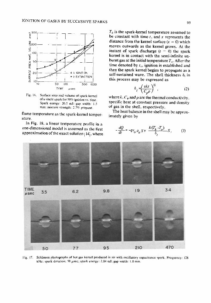
Figure 16 shows the surface area and volume of the spark kernel produced with a single spark of 20.5 mJ energy which gives 50% igni-
tion for the same mixture strength and gap width as those shown in Fig. 15. In the case of ignition the spark kernel develops as a torus until 1 msec and then propagates with a spheri- cal shape. In Fig. 16 there is no difference between the size of both spark kernels until 200 p, sec, at which time they either grow to ignition or decay to extinction. Therefore, it is thought that ignition is established at about 200/xsec; this can be considered as the minimum time required for ignition. This situation should also hold true for the case of Fig. 15, since the same gap width and mixture strength are used as those in Fig. 16. Figure 15 shows that both the surface area and volume of the spark kernel for ignition are smaller than those for extinction during the above-mentioned time required for ignition. This fact is also observable for other c o m b i n a t i o n s o f gap wid th and m i x t u r e strength.
From these results the following conclusion is derived: The higher igniting ability of two

92 M. KONO, S. KUMAGAI, AND T. SAKA1
TIME 9.8 I 5 19 25 3 4 /~sec
Fig. 11. p.sec; other legends are the same as in Fig. 10.
successive sparks of optimum time interval than that of a single spark comes from the smal- ler size of the spark kernel during the time required for ignition and this is possibly due to smaller heat loss.
5 0 9 5 210 470 I 0 0 0 Schlieren photographs of spark kernel produced with two successive sparks (extinction). Spark interval: 10
4. Comparison of Spark Kernel of Oscillatory Sparks and Two Successive Sparks As shown in Fig. 9, the igniting ability of the two successive sparks is highest at a spark interval of 10 to 50 /~sec, though its value changes slightly with the gap width. Assuming that such a spark interval is equivalent to the half-cycle period of the oscillatory discharge in a capacitance spark, the frequency corres- ponding to the two successive sparks is 50 to 10 kHz. This range of frequency is in reasonable agreement with the previously determined fre- quency of about 100 kHz for the highest ignit- ing ability.
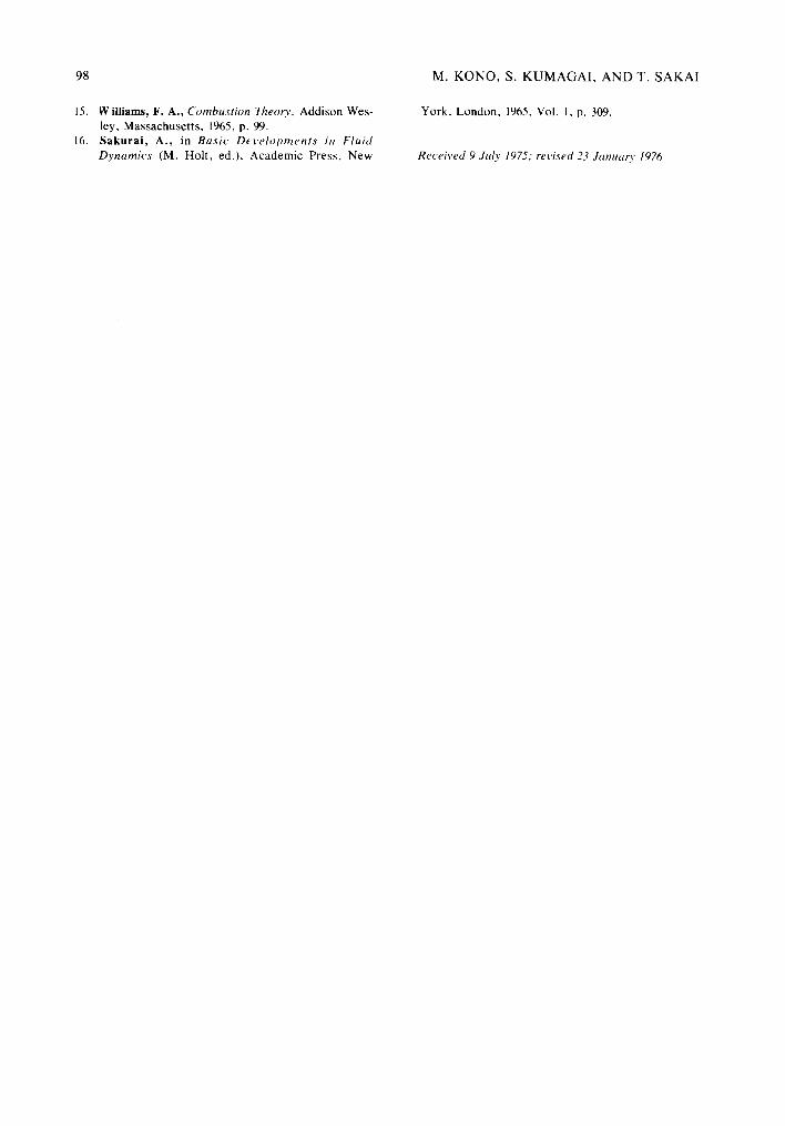
Figure 17 shows the schlieren photographs for a hot gas kernel in air produced with an
oscillatory capacitance spark of 2.04 mJ ener- gy, 128 kHz frequency and 50/~sec duration for 1.0 mm gap width. This particular value of fre- quency has been chosen because it corres- ponds to the case of the highest igniting ability shown in Figs. 4 and 5. The hot gas kernel in air and the spark kernel in propane-air mixtures take a shape similar to each other during their incipient periods. Moreover, it is found that the spark kernel after the second spark passage (23 p.sec) in Fig. 12 is similar to the hot gas kernel in air in Fig. 17. This similarity suggests that effects of the frequency of a single oscillat- ory spark or the interval of two successive sparks on the igniting ability may be mainly attributed to the modes of the spark-kernel de- velopment and its transition to a flame at ap- proximately 200~sec after the first spark pas- sage.
5. Analysis of Igniting Ability In order to verify the experimental fact that two

IGNITION OF GASES BY SUCCESSIVE SPARKS 93
TIME I 9 25 2 9 .34 4 I ~sec
Fig. 12. other legends are the same as in Fig. 10.
successive sparks of a certain interval show a higher igniting ability than a single spark, a simplified thermal theory is employed.
Consider the heat balance in a shell outside the spark kernel during the time required for ignition, where the chemical heat liberation and the thermal conduction from the spark kernel coexist. As the chemical heat liberation in this period is insufficient to maintain a temp- erature gradient larger than that in a steady- state laminar-flame propagation, the insuffi- ciency has to be compensated by the spark energy for the establishment of ignition. For the spark energy, Edmonson al. [6] and Olsen et al. [7] indicated that a considerable part of the spark energy is lost due to the shock-wave formation immediately (the order of 10/zsec) after the spark discharge. From their results obtained with the spark energy of several mil- lijoules, it is estimated that about 20% of the spark energy remains in the spark kernel after 10 /zsec. This remainder is the only energy available for ignition.
5 0 9 5 210 4 7 0 I 0 0 0 Schlieren photographs of spark kernel produced with two successive sparks (ignition). Spark interval: 23 p.sec;
The adiabatic equilibrium temperature of the spark kernel in Fig. 15 are calculated after Harker [8,9] using the values of volume of the spark kernel shown and the useful 20% (0.816 m J) of the spark energy (4.08 m J). In this calcu- lation, it is assumed that the temperature, pres- sure and concentration of species are uniform throughout the spark kernel. The calculated tempera tures cannot be employed for the period during l0/~sec after the spark discharge, since the temperature and pressure in the spark kernel may not come to equilibrium [10, 7]. As is eeen in Fig. 15, the temperatures for the two cases are nearly equal to each other with values close to 1850 °K. This is the adiabatic equilib- rium temperature of a laminar flame propagat- ing in a 2.7% propane-air mixture. However, even if the heat loss from the spark kernel to the spark electrodes is neglected, the value of 20% may still be larger than the true value, because an appreciable amount of spark energy is lost from the hot air kernel by radiation [11] . Fur- thermore, excellent agreement is obtained be-

94 M. KONO, S. KUMAGAI, AND T. SAKAI
TIME ~sec 3 8 4 4 50 6 0 67
Fig. 13. 41/,Lsec; other legends are the same as in Fig. 10.
tween the experimental measurement of the motion of the shock wave and the theoretical estimation [12, 13]. Hence, the actual tempe rature of the spark kernel is much nearer the adiabatic flame temperature than that shown in ~ eoo
KERNEL ~ Ioo
O
> 5o
E < 2o
I J
77 95 210 470 I 0 0 0
Schlieren photographs of spark kernel produced with two successive sparks (extinction). Spark interval:
ELECTRODES
Fig, 14. Schematic drawing of unburnt gas flow induced by spark discharge.
Fig. 15. In a simple theoretical treatment, therefore, it is reasonable to use the adiabatic
Fig. 15.
3000
r~
!O(X)
Ld
I 0 0 0 z rY
I I / I I IO 20 50 I00 200 500 I000
T I M E #sec
Surface area, volume and temperature (calcu- lated) of spark kernel vs. time from the first spark. Comparison of extinction with a single spark and ignition with two successive sparks. Spark interval: 41 /zsec; gap width: 1.5 m m ;
spark energy: 2.04 mJ each.
IGNITION OF GASES BY SUCCESSIVE SPARKS 95
500 [
I0 50 I00 500 I000
TIME ~sec
Fig. 16. Surface area and volume of spark kernel ofa sincle spark for 50% ignition vs. time. Spark energy: 20.5 mJ; gap width: 1.5 ram: mixture strength: 2.7% propane.
flame temperature as the spark-kernel temper- ature.
In Fig. 18, a linear temperature profile in a one-dimensional model is assumed as the first approximation of the exact solution [14 l, where
Tk is the spark-kernel temperature assumed to be constant with time t, and x represents the distance from the kernel surface (x = 0) which moves outwards as the kernel grows. At the instant of spark discharge (t = 0) the spark kernel is in contact with the semi-infinite un- burnt gas at the initial temperature To. After the time denoted by te, ignition is established and then the spark kernel begins to propagate as a self-sustained wave. The shell thickness 8t in this process may be expressed as
{ ~rkt ~'~ 8 , (2) t ~
where k, Cp and O are the thermal conductivity, specific heat at constant pressure and density of gas in the shell, respectively.
The heat balance in the shell may be approx- imately given by
dQ k(rk-r°) s, (3) dt - -qVo Po S + 6 t
TIME #sec 5.5 6.2 9.8 1 9 3 4
Fig. 17.
5O 7 7 9 5 210 470
Schlieren photographs of hot gas kernel produced in air with oscillatory capacitance spark. Frequency: 128 kHz: spark duration: 50/zsec; spark energy: 2.04 mJ; gap width: 1.0 ram.

96 M. KONO, S. KUMAGAI, AND T. SAKAI
T
UNBURNT
Fig. 18. Schematic drawing of temperature profile in shell outside spark kernel.
where Q and S are the heat loss and surface area of the spark kernel, respectively, q, Vo and po being the heat of reaction, flow velocity and density of the unburnt mixture, respectively. The first and second terms in the fight hand side of Eq. (3) correspond to the chemical heat liberation in the shell and the heat flow from the spark kernel by conduction, respectively. From Eqs. (2) and (3), the rate of heat loss dQ/dt can be calculated, the results being shown in Fig. 19. In this calculation, the values fork, C, and p at the arithmetric mean tempera- ture of air (Tk + To)~2, the laminar burning veloc- ity for %, the adiabatic flame temperature for Tk and the value of S given in Fig. 15 are used for simplicity.
Another utility of Eq. (3) is to give the time required for ignition te, which is obtained from dQ/dt =0 as
Cppk (Tk-T°) 2. (4)
re- qVop o
The calculated value of te for a 2.7% propane- air mixture is 114/~sec, which is in very good agreement with the experimentally determined value of about 200/~sec as shown in Fig. 16.
Figure 19 shows that the rate of heat loss for two successive sparks is smaller than that for a single spark during the time required for igni- tion, and hence the heat loss for the ignition period, which corresponds to the area under the curve, is also smaller for two successive sparks. Thus the higher igniting ability of two successive sparks when compared with that of a single spark is sufficiently explained by the difference in the heat Joss from the spark ker-
nel. This analysis holds true also for the effect of frequency on the igniting ability of capci- tance sparks, because the successive spark theory shows clearly that their igniting ability can be mainly attributed to spark-kernel be- havior.
In connection with the justification of Eq. (3), substituting Eq. (4) into Eq. (2) and using the relation
q = cp - To) , (s )
the value of St at t = te can be given as
° t = CTkoPo (6)
This value coincides with the thickness of the laminar flame [ 15], so that the present analysis is considered to be valid.
6. Gas Flow Induced by Spark Discharge
In Fig. 10 it appears that the gas flow as shown in Fig. 14 exists, which is possibly induced by the shock wave associated with spark dis- charge. After the spark discharge, an outward gas flow follows behind the shock front [16]. This flow distorts the initially cylindrical spark kernel into a torus and then controls its be- havior. From the present experiments the ignit- ing ability of a capacitance spark is found to relate closely to the spark-kernel behavior, which is affected by the gas flow in turn. The pattern and velocity of the gas flow depend on the electrode configuration and the amount of
o~ ~ ~ 5 . 0 ~
-6
rY m2.5 (/3 o - [ ~ , ~ I - SPARK
W T
0 4 0 8 0 120
T I M E /~sec
Fig. 19. Heat loss rate (calculated) from spark kernel vs. time from the first spark. Data correspond to Fig. 15.

IGNITION OF GASES BY SUCCESSIVE SPARKS 97
spark energy, though they are also affected by the energy per unit length of the spark path for an especially large gap width [16]. To verify this, the spark-kernel behavior of a capacitance spark was observed on schlieren photographs for two cases; one by using spark electrodes with flanges and the other, needle electrodes of a large gap width (5.0 mm).
In the former case, such gas flow as shown in Fig. 14 is found to be blocked and the spark kernel develops in a quite cylindrical shape between the flanges. This fact suggests that this electrode configuration controls both the quenching effect due to the conductive heat loss to the electrodes and also the gas flow near the spark kernel; both of these affect the igniting ability of sparks interdependently. In the latter case, the gas-flow velocity is found to be considerably reduced and subsequently the spark kernel develops gradually in a cylindrical shape around the initial spark path.
It is clear from the present experiments that the effects of the discharge frequency or the spark interval relate to the different behaviors of the spark kernel which are considered to come from the gas-flow condition. Therefore, in the case of needle electrodes of a large gap width in which the gas flow is reduced, the igniting ability of the capacitance spark may not be affected by the discharge frequency or the spark interval. This situation may probably correspond to the experiment which was con- ducted by Blanc et al. [5]; they investigated the frequency effects with a considerably larger gap width for the purpose of avoiding the quenching effect by electrodes as much as pos- sible, although the frequency range that they employed is unknown.
7. Conclusions
(1) The effect of the discharge frequency of a capacitance spark under the oscillatory con- dition on the igniting ability has been investi- gated using lean propane-air mixtures. It is shown that the igniting ability reaches a maximum at a discharge frequency of about 100 kHz.
(2) In order to confirm the frequency effect
mentioned above, a spark of very short dura- tion is substituted for each half of the first cycle of an oscillatory discharge and the igniting abil- ity of two successive sparks with various time intervals has been investigated. It is found that the igniting ability reaches a maximum at a spark interval of 10 to 50 t~sec, which corre- sponds to the discharge frequency of 50 to l0 kHz.
(3) The order-of-magnitude agreement of the frequency for the above two cases means that a predominant factor in ignition by a capacitance spark is the discharge frequency.
(4) From the flash-schlieren photographs of incipient spark kernels, it is suggested that the igniting ability is related to the heat loss from the spark kernel to the unburnt mixture, which varies according to the shape of the spark kernel during the period required for igni- tion.
(5) A simplified thermal theory based on observations explains the frequency effect in ignition by capacitance sparks.
References 1. Finch, G. I. and Thompson, H. H., Proc. Roy. Soe.
(London) A 134, 343 (1931); Bradford, B. W. and Finch, G. I., Chem Revs. 21,221 (1937).
2. Toriyama, Y., Saito, S. and Saito, R., Appl. Phys. Japan 12,463 (1943).
3. Courtney, W. G., Clark, W. J. and Slough, C. M., ARS J. 32, 1530 (1962).
4. Lewis, B. and van EIbe, G., Combustion, Flumes and Explosions o f Gases, Academic Press. New York, 1951, p. 419.
5. Blanc, M. V., Guest, P. G., von Elb¢; G. and Lewis, B., J. Chem. Phys. 15, 798 (1947).
6. Edmonson, R B., Olsen, H. L. and Gayhart, E. L., J. Appl. Phys. 25, 1008 (1954).
7. Olsen, H. L., Edmonson, R. B. and Gayhart, E. L., J. Appl. Phys. 23, 1157 (1952).
8. Harker, J. H., J. Inst. Fuel 40, 206 (1967). 9. Harker, J. H. and Allen, D. A., Inst. Fuel 42, 183
(1969). 10. Marteney, P. J., Comb. Sci. Teehnol. 1., 461 (1970). 11. Piooster, M. N., Phys. Fluids 14, 2111 (1971). 12. Freeman, R. A., Brit. J. Appl. Phys. (J. Phys. D.) 1,
1697 (1967). 13. Freeman, R. A. and Craggs, J. D., Brit. J. Appl. Phys.
(J. Phys. D.) 2, 421 (1969). 14. Carslow, H. S. and Jaeger, J. C., Conduction o f Heat
in Solids, 2nd ed., Oxford at the Clarendon Press, 1959, p. 51, p. 482.
98
15.
16.
Williams, F. A., Combustion Theory, Addison Wes- ley, Massachusetts, 1965, p. 99. Sakurai, A., in Basic Deve lopment s in Fluid Dynamics (M. Holt, ed.), Academic Press, New
M. K O N O , S. K U M A G A I , A N D T. S A K A I
York, London, 1965, Vol. 1, p. 309.
Received 9 Jtdy 1975: revised 23 January 1976