ii - process calibration equipment | metrology equipment
TRANSCRIPT

I

II
STATEMENT
This user manual provides operating and safety instructions for the ADT760 Automatic Handheld
Pressure Calibrator. To ensure correct operation and safety, please follow the instructions in this
manual. Additel Corporation reserves the right to change the contents and other information
contained in this manual without notice.
III
CONTENT Welcome ............................................................................................................................................................... 1
How to Contact Additel ......................................................................................................................................... 1
Safety Information ................................................................................................................................................ 2
1. Introduction ...................................................................................................................................................... 5
1.1 Model Information .................................................................................................................................. 5
1.2 Basic Structure ........................................................................................................................................ 6
1.3 Features................................................................................................................................................... 8
1.3 Features................................................................................................................................................... 8
1.4 Technical Specification ............................................................................................................................ 9
1.4.1 General Specification ................................................................................................................... 9
1.4.2 Environment Specification ......................................................................................................... 10
1.4.3 Electrical Specification ............................................................................................................... 11
1.4.4 Internal Modules Specification .................................................................................................. 11
1.5 Power .................................................................................................................................................... 14
1.6 Standard Equipment ............................................................................................................................. 15
2. Get Started ...................................................................................................................................................... 17
2.1 Battery ................................................................................................................................................... 17
2.2 Internal Pressure Module ...................................................................................................................... 20
2.3 Starting the Calibrator ........................................................................................................................... 21
2.4 Electric Connections .............................................................................................................................. 21

IV
2.5 Pressure Connection ............................................................................................................................. 23
3. Operation ........................................................................................................................................................ 24
3.1 Display and Operation ........................................................................................................................... 24
3.1.1 Main Screen ............................................................................................................................... 24
3.1.2 Pressure Unit .............................................................................................................................. 26
3.1.3 Pressure Output ......................................................................................................................... 27
3.1.4 Current/Voltage Measurement .................................................................................................. 32
3.1.5 Mechanical Switch ..................................................................................................................... 34
3.1.6 NPN /PNP Switch ........................................................................................................................ 35
3.1.7 Current Output ........................................................................................................................... 36
3.1.8 External Pressure Module .......................................................................................................... 38
3.2 HART (Only available on 760-X-DL) ....................................................................................................... 40
3.2.1 Poll .............................................................................................................................................. 40
3.2.2 Operation Window ..................................................................................................................... 42
3.2.3 Settings ....................................................................................................................................... 43
3.2.4 Service ........................................................................................................................................ 46
3.2.5 Process ....................................................................................................................................... 49
3.3 Zeroing .................................................................................................................................................. 50
3.4 Vent ....................................................................................................................................................... 50
4. Typical Applications ......................................................................................................................................... 51
4.1 Pressure Gauge (Includes dial and digital pressure gauges) ................................................................. 52
4.2 Current / Voltage Transmitter ............................................................................................................... 54
V
4.3 HART Transmitter .................................................................................................................................. 56
4.4 Pressure Switch ..................................................................................................................................... 58
4.5 I/P Converter ......................................................................................................................................... 60
4.6 Documenting ......................................................................................................................................... 62
5. Setup ............................................................................................................................................................... 64
5.1 Control Settings ..................................................................................................................................... 64
5.2 24V Power ............................................................................................................................................. 64
5.3 Communication ..................................................................................................................................... 65
5.4 Head Correction .................................................................................................................................... 65
5.5 Services ................................................................................................................................................. 67
5.5.1 Calibration .................................................................................................................................. 67
5.5.2 Diagnosis .................................................................................................................................... 72
5.5.3 System Log ................................................................................................................................. 72
5.5.4 Maintenance .............................................................................................................................. 73
5.5.5 Factory Reset .............................................................................................................................. 73
5.5.6 Updates ...................................................................................................................................... 73
5.6 Sound .................................................................................................................................................... 74
5.7 Personalization ...................................................................................................................................... 74
5.7.1 Date and Time ............................................................................................................................ 74
5.7.2 Language .................................................................................................................................... 74
5.7.3 Theme ........................................................................................................................................ 75
5.7.4 Safety Data ................................................................................................................................. 75
VI
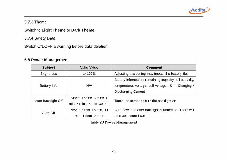
5.8 Power Management .............................................................................................................................. 75
5.9 System Information ............................................................................................................................... 76
6. Task (Only available on 760-X-DL) ................................................................................................................... 77
6.1 New Task ............................................................................................................................................... 77
6.1.1 Dial Pressure Gauge ................................................................................................................... 78
6.1.2 Digital Pressure Gauge ............................................................................................................... 79
6.1.3 Pressure Transmitter (Current, Voltage, HART) .......................................................................... 80
6.1.4 Pressure Switch .......................................................................................................................... 81
6.1.5 I/P Converter .............................................................................................................................. 82
6.2 Task Execution ....................................................................................................................................... 83
6.2.1 Dial Pressure Gauge ................................................................................................................... 83
6.2.2 Digital Pressure Gauge ............................................................................................................... 85
6.2.3 Pressure Transmitter (Current, Voltage, HART) .......................................................................... 87
6.2.4 Pressure Switch .......................................................................................................................... 89
6.2.5 I/P Converter .............................................................................................................................. 90
6.3 Task Delete ............................................................................................................................................ 91
6.4 End of Task ............................................................................................................................................ 92
7. Data Logger (Only available on 760-X-DL) ....................................................................................................... 93
8. Application ...................................................................................................................................................... 95
8.1 Leak Test ................................................................................................................................................ 95
8.2 Pressure Unit Converter ........................................................................................................................ 96
9. Service ............................................................................................................................................................. 97
VII
9.1 Inlet Port Filter ...................................................................................................................................... 97
9.2 Pressure Outlet Port Filter and O-ring (Same as REF port) ................................................................... 98
Appendix 1: SCPI List ........................................................................................................................................... 99
A1.1 IEEE488.2 ............................................................................................................................................ 99
A1.2 Measurement and configuration ...................................................................................................... 101
A1.3 Output ............................................................................................................................................... 107
A1.4 Calculation ........................................................................................................................................ 110
A1.5 System ............................................................................................................................................... 111
A1.6 Status ................................................................................................................................................ 118
A1.7 Unit ................................................................................................................................................... 119
A1.8 Data Record....................................................................................................................................... 120
A1.9 HART ................................................................................................................................................. 123
Appendix 2: Unit ............................................................................................................................................... 127
Appendix 3: Software ........................................................................................................................................ 129
A3.1 Additel ACal ...................................................................................................................................... 131
A3.2 Additel PCal ....................................................................................................................................... 134
A3.3 Additel Land ...................................................................................................................................... 139
A3.4 Additel Log II ..................................................................................................................................... 142
A3.5 How to install ADT760 Driver by using Zadig .................................................................................... 145
VIII
Table Content Table 1 Symbols ............................................................................................................................................. 4
Table 2 Model Information............................................................................................................................ 5
Table 3 Basic Structure .................................................................................................................................. 7
Table 4 Electrical Specification .................................................................................................................... 11
Table 5 Selection Guide-Differential Pressure ............................................................................................. 13
Table 6 Selection Guide-Gauge Pressure .................................................................................................... 14
Table 7 Standard Equipment ....................................................................................................................... 15
Table 8 Electric Connections ....................................................................................................................... 22
Table 9 Pressure Output Control Settings ................................................................................................... 27
Table 10 Auto Step ...................................................................................................................................... 30
Table 11 Min / Max / Avg ............................................................................................................................ 33
Table 12 Scale .............................................................................................................................................. 33
Table 13 External Pressure Module Information ........................................................................................ 39
Table 14 HART Device Information ............................................................................................................. 43
Table 15 ART device sensor information ..................................................................................................... 44
Table 16 HART Device Output ..................................................................................................................... 45
Table 17 HART Device Variable ................................................................................................................... 49
Table 18 Pressure Gauge Test Settings ........................................................................................................ 52
Table 19 Current / Voltage Transmitter Test Settings .................................................................................. 54
Table 20 HART Device Test Settings ............................................................................................................ 56
IX
Table 21 Pressure Switch Test Settings ........................................................................................................ 58
Table 22 I/P Converter Test Settings ........................................................................................................ 61
Table 23 Test Information ............................................................................................................................ 62
Table 24 Test Save Options .......................................................................................................................... 63
Table 25 Communication Settings ............................................................................................................... 65
Table 26 Head Pressure Correction ............................................................................................................. 66
Table 27 Date and Time Settings ................................................................................................................. 74
Table 28 Power Management ..................................................................................................................... 75
Table 29 Dial Pressure Gauge Information Settings .................................................................................... 78
Table 30 Pressure Transmitter Information Settings ................................................................................... 80
Table 31 Pressure Switch Information Settings ........................................................................................... 81
Table 32 I/P Converter Information Settings ............................................................................................... 82
Table 33 Dial Pressure Gauge Task Settings ................................................................................................ 83
Table 34 Digital Pressure Gauge Task Settings ............................................................................................ 85
Table 35 Pressure Transmitter Task Settings ............................................................................................... 87
Table 36 Pressure Switch Task Settings ....................................................................................................... 89
Table 37 I/P Converter Task Settings ........................................................................................................... 90
Table 38 Task Save Operation ...................................................................................................................... 92
Table 39 Data Logger Setup ......................................................................................................................... 94
Table 40 Data Logger Chart ......................................................................................................................... 94
Table 41 Leak Test ....................................................................................................................................... 95
X
Figure Content Figure 1 Basic Structure ................................................................................................................................ 6
Figure 2 Standard Equipment...................................................................................................................... 16
Figure 3 Battery Install and Charging .......................................................................................................... 18
Figure 4 Internal Pressure Module Switching ............................................................................................. 20
Figure 5 Electric Connection ....................................................................................................................... 21
Figure 6 Pressure Connection ..................................................................................................................... 23
Figure 7 Main Screen .................................................................................................................................. 25
Figure 8 Output Connection ........................................................................................................................ 28
Figure 9 Current / Voltage Measurement ................................................................................................... 32
Figure 10 Mechanical Switch Measurement ............................................................................................... 34
Figure 11 Electrical Switch Measurement ................................................................................................... 35
Figure 12 Current Output ............................................................................................................................ 36
Figure 13 External Pressure Module Connection ........................................................................................ 38
Figure 14 HART Device (Internal Power, Internal Resistor) ......................................................................... 40
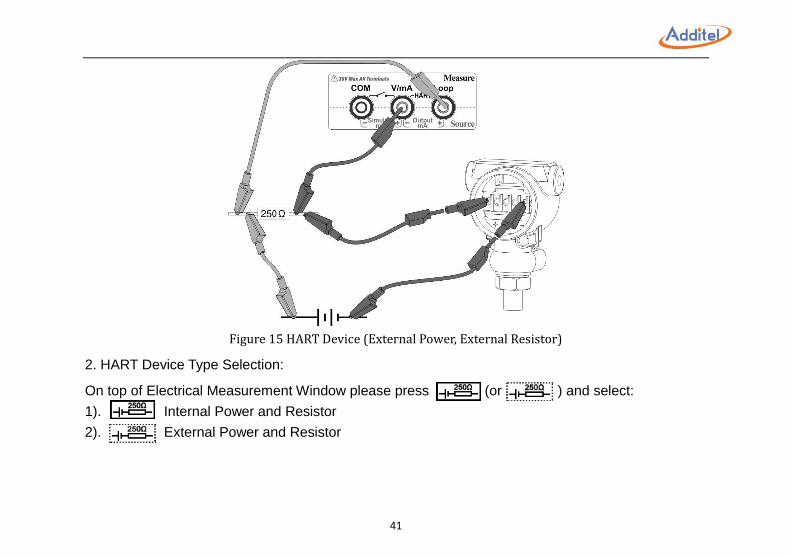
Figure 15 HART Device (External Power, External Resistor) ........................................................................ 41
Figure 16 Jog Function ................................................................................................................................ 52
Figure 17 Barometer Sensor Calibration ..................................................................................................... 71
Figure 18 Inlet Port Filter ............................................................................................................................ 97
XI
Figure 19 REF and Outlet Port Filter ............................................................................................................ 98
1
Welcome The Additel 760 Automatic Handheld Pressure Calibrator is a hand held controller, as well as a documenting process
calibrator, all rolled into one with high precision and control stability. Each unit comes with an internal pressure module
ranged to cover the full scale range of the unit. The internal module is located at the back of the calibrator and is
removable allowing for the selection of lower range pressure to improve accuracy. In addition, the calibrator can work
with two external pressure modules at the same time. With high precision electrical signal measurement function, this
calibrator can be used for dial pressure gauges, digital pressure gauges, differential pressure gauges, pressure
transmitters, I/P converters, or pressure switch calibration. For the most up-to-date manual, please visit
www.additel.com.
How to Contact Additel Additel Corporation
Phone: +1-714-998-6899
Fax:+1-714-998-6999
E-mail: [email protected] or [email protected]
Website: www.additel.com

2
Safety Information
WARNINGS identify action or condition that may be hazards to the user;
CAUTIONS identify action or condition that may damage the calibrator or the equipment under test.
WARNINGS:
To prevent personal injury, please follow this user manual.
To prevent possible electrical shock, fire, or personal injury, please:
Check product exterior before use
Read and follow all instructions carefully
Do NOT apply more than 30V AC or DC between any two electric jacks
Correctly place and lock the battery before use
Avoid close contact to the vent port when venting
Charge the battery immediately with supplied power adapter when the low battery indication occurs. This will
prevent potential pressure release due to a loss of electrical power
Do NOT use the product if it is damaged or operates incorrectly
Do NOT use in flammable, high humidity, or dusty environments
Only use accessories, test leads, and probes that have the same measurement specification
3
CAUTIONS:
Do NOT shake, drop, or bump the calibrator while in use
If condensation occurs, thoroughly dry out the calibrator before startup
Do NOT use any power adapter other than 9816-X
Charge the battery immediately when low battery symbol indicates
Do not remove the battery while it is in charging or when the calibrator is in use
Release the system pressure before turning off the calibrator
4
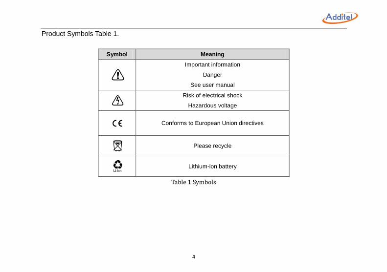
Product Symbols Table 1.
Symbol Meaning
Important information
Danger
See user manual
Risk of electrical shock
Hazardous voltage
Conforms to European Union directives
Please recycle
Lithium-ion battery
Table 1 Symbols
5
1. Introduction
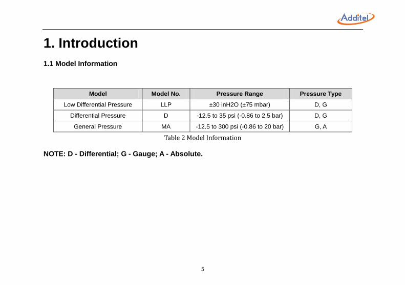
1.1 Model Information
Model Model No. Pressure Range Pressure Type
Low Differential Pressure LLP ±30 inH2O (±75 mbar) D, G
Differential Pressure D -12.5 to 35 psi (-0.86 to 2.5 bar) D, G
General Pressure MA -12.5 to 300 psi (-0.86 to 20 bar) G, A
Table 2 Model Information
NOTE: D - Differential; G - Gauge; A - Absolute.
6
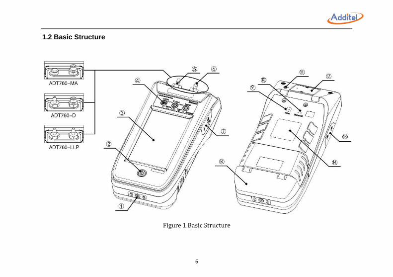
1.2 Basic Structure
Figure 1 Basic Structure
7
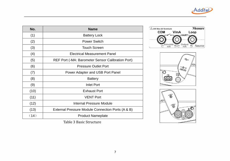
No. Name
(1) Battery Lock
(2) Power Switch
(3) Touch Screen
(4) Electrical Measurement Panel
(5) REF Port (-MA: Barometer Sensor Calibration Port)
(6) Pressure Outlet Port
(7) Power Adapter and USB Port Panel
(8) Battery
(9) Inlet Port
(10) Exhaust Port
(11) VENT Port
(12) Internal Pressure Module
(13) External Pressure Module Connection Ports (A & B)
(14) Product Nameplate
Table 3 Basic Structure
8
1.3 Features
Fully automatic calibrator with built-in pump and controller
Switchable internal pressure modules for expandable ranges
Accuracy (1 year) of 0.02%FS
External pressure modules available (measurement only)
Less than 4 lbs. (1.8 kg) for handheld operation
Source pressure, measure pressure and measure electrical
4 channels
Optional HART communication
Optional data logging and documentation
USB, Wi-Fi, and Bluetooth communications
1.3 Features
9
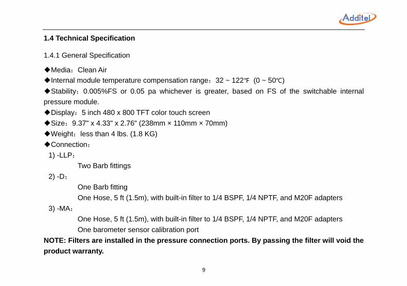
1.4 Technical Specification
1.4.1 General Specification
◆Media:Clean Air
◆Internal module temperature compensation range:32 ~ 122℉ (0 ~ 50℃)
◆Stability:0.005%FS or 0.05 pa whichever is greater, based on FS of the switchable internal
pressure module.
◆Display:5 inch 480 x 800 TFT color touch screen
◆Size:9.37" x 4.33" x 2.76" (238mm × 110mm × 70mm)
◆Weight:less than 4 lbs. (1.8 KG)
◆Connection:
1) -LLP:
Two Barb fittings
2) -D:
One Barb fitting
One Hose, 5 ft (1.5m), with built-in filter to 1/4 BSPF, 1/4 NPTF, and M20F adapters
3) -MA:
One Hose, 5 ft (1.5m), with built-in filter to 1/4 BSPF, 1/4 NPTF, and M20F adapters
One barometer sensor calibration port
NOTE: Filters are installed in the pressure connection ports. By passing the filter will void the
product warranty.
10
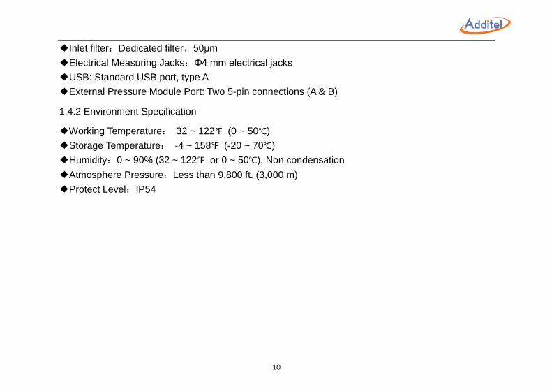
◆Inlet filter:Dedicated filter,50μm
◆Electrical Measuring Jacks:Φ4 mm electrical jacks
◆USB: Standard USB port, type A
◆External Pressure Module Port: Two 5-pin connections (A & B)
1.4.2 Environment Specification
◆Working Temperature: 32 ~ 122℉ (0 ~ 50℃)
◆Storage Temperature: -4 ~ 158℉ (-20 ~ 70℃)
◆Humidity:0 ~ 90% (32 ~ 122℉ or 0 ~ 50℃), Non condensation
◆Atmosphere Pressure:Less than 9,800 ft. (3,000 m)
◆Protect Level:IP54
11
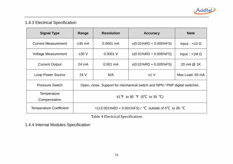
1.4.3 Electrical Specification
Signal Type Range Resolution Accuracy Note
Current Measurement ±30 mA 0.0001 mA ±(0.01%RD + 0.005%FS) Input:<10 Ω
Voltage Measurement ±30 V 0.0001 V ±(0.01%RD + 0.005%FS) Input:>1M Ω
Current Output 24 mA 0.001 mA ±(0.01%RD + 0.005%FS) 20 mA @ 1K
Loop Power Source 24 V N/A ±1 V Max Load: 50 mA
Pressure Switch Open, close. Support for mechanical switch and NPN / PNP digital switches.
Temperature
Compensation 41℉ to 95 ℉ (5℃ to 35 ℃)
Temperature Coefficient <(±0.001%RD + 0.001%FS) / ℃ outside of 5℃ to 35 ℃
Table 4 Electrical Specification
1.4.4 Internal Modules Specification
12
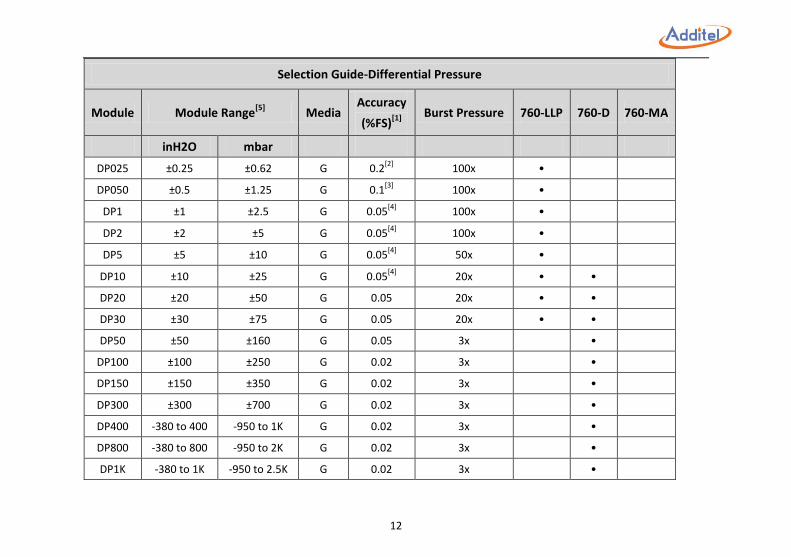
Selection Guide-Differential Pressure
Module Module Range[5]
Media Accuracy
(%FS)[1]
Burst Pressure 760-LLP 760-D 760-MA
inH2O mbar
DP025 ±0.25 ±0.62 G 0.2[2]
100x •
DP050 ±0.5 ±1.25 G 0.1[3]
100x •
DP1 ±1 ±2.5 G 0.05[4]
100x •
DP2 ±2 ±5 G 0.05[4]
100x •
DP5 ±5 ±10 G 0.05[4]
50x •
DP10 ±10 ±25 G 0.05[4]
20x • •
DP20 ±20 ±50 G 0.05 20x • •
DP30 ±30 ±75 G 0.05 20x • •
DP50 ±50 ±160 G 0.05 3x •
DP100 ±100 ±250 G 0.02 3x •
DP150 ±150 ±350 G 0.02 3x •
DP300 ±300 ±700 G 0.02 3x •
DP400 -380 to 400 -950 to 1K G 0.02 3x •
DP800 -380 to 800 -950 to 2K G 0.02 3x •
DP1K -380 to 1K -950 to 2.5K G 0.02 3x •
13
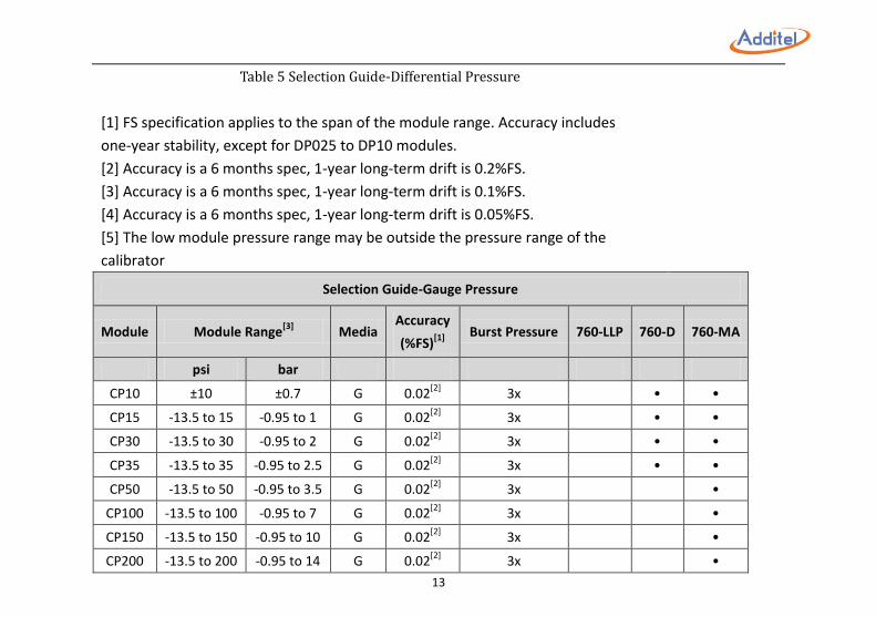
Table 5 Selection Guide-Differential Pressure
[1] FS specification applies to the span of the module range. Accuracy includes
one-year stability, except for DP025 to DP10 modules.
[2] Accuracy is a 6 months spec, 1-year long-term drift is 0.2%FS.
[3] Accuracy is a 6 months spec, 1-year long-term drift is 0.1%FS.
[4] Accuracy is a 6 months spec, 1-year long-term drift is 0.05%FS.
[5] The low module pressure range may be outside the pressure range of the
calibrator
Selection Guide-Gauge Pressure
Module Module Range[3]
Media Accuracy
(%FS)[1]
Burst Pressure 760-LLP 760-D 760-MA
psi bar
CP10 ±10 ±0.7 G 0.02[2]
3x • •
CP15 -13.5 to 15 -0.95 to 1 G 0.02[2]
3x • •
CP30 -13.5 to 30 -0.95 to 2 G 0.02[2]
3x • •
CP35 -13.5 to 35 -0.95 to 2.5 G 0.02[2]
3x • •
CP50 -13.5 to 50 -0.95 to 3.5 G 0.02[2]
3x •
CP100 -13.5 to 100 -0.95 to 7 G 0.02[2]
3x •
CP150 -13.5 to 150 -0.95 to 10 G 0.02[2]
3x •
CP200 -13.5 to 200 -0.95 to 14 G 0.02[2]
3x •
14
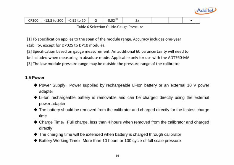
CP300 -13.5 to 300 -0.95 to 20 G 0.02[2]
3x •
Table 6 Selection Guide-Gauge Pressure
[1] FS specification applies to the span of the module range. Accuracy includes one-year
stability, except for DP025 to DP10 modules.
[2] Specification based on gauge measurement. An additional 60 pa uncertainty will need to
be included when measuring in absolute mode. Applicable only for use with the ADT760-MA
[3] The low module pressure range may be outside the pressure range of the calibrator
1.5 Power
Power Supply:Power supplied by rechargeable Li-Ion battery or an external 10 V power
adapter
Li-Ion rechargeable battery is removable and can be charged directly using the external
power adapter
The battery should be removed from the calibrator and charged directly for the fastest charge
time
Charge Time:Full charge, less than 4 hours when removed from the calibrator and charged
directly
The charging time will be extended when battery is charged through calibrator
Battery Working Time:More than 10 hours or 100 cycle of full scale pressure
15
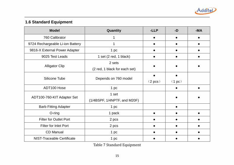
1.6 Standard Equipment
Model Quantity -LLP -D -MA
760 Calibrator 1 ● ● ●
9724 Rechargeable Li-ion Battery 1 ● ● ●
9816-X External Power Adapter 1 pc ● ● ●
9025 Test Leads 1 set (2 red, 1 black) ● ● ●
Alligator Clip 2 sets
(2 red, 1 black for each set) ● ● ●
Silicone Tube Depends on 760 model ●
(2 pcs)
●
(1 pc)
ADT100 Hose 1 pc ● ●
ADT100-760-KIT Adapter Set 1 set
(1/4BSPF, 1/4NPTF, and M20F) ● ●
Barb Fitting Adapter 1 pc ●
O-ring 1 pack ● ● ●
Filter for Outlet Port 2 pcs ● ● ●
Filter for Inlet Port 2 pcs ● ● ●
CD Manual 1 pc ● ● ●
NIST-Traceable Certificate 1 pc ● ● ●
Table 7 Standard Equipment
16
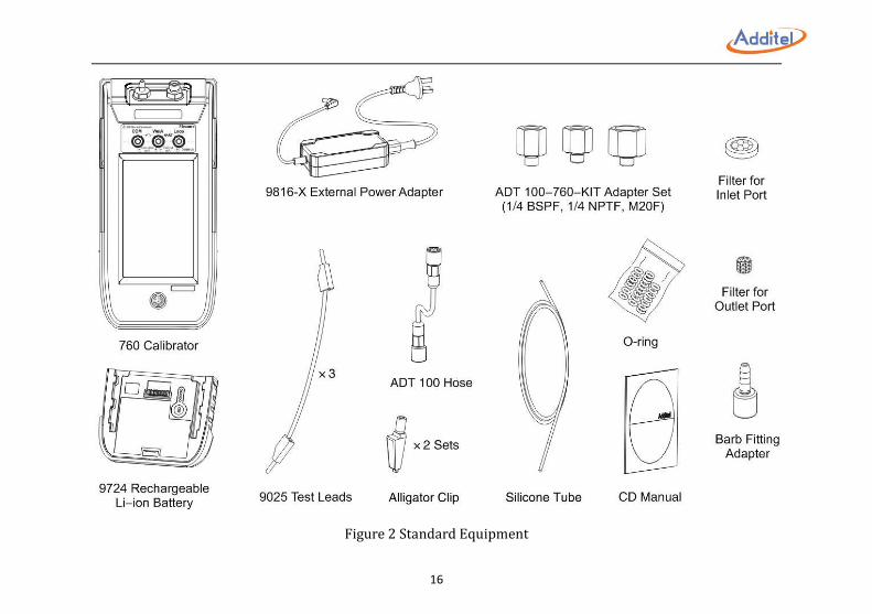
Figure 2 Standard Equipment
17
2. Get Started
2.1 Battery
WARNINGS:
Lithium-ion batteries may get hot or ignite and cause serious injury if not treated properly
Do NOT incinerate or heat the battery
Do NOT storage the battery in direct sunlight
Do NOT try to disassemble the battery
The battery contains dangerous chemical substances
Please clean with water and look for medical treatment if exposure to chemicals occurs
Continuously charging the battery of this unit will significantly reduce the life of the battery
CAUTIONS:
Please remove the battery and store in a cool, dry, ventilated area if it will not be used for a long period
Do not store batteries with hazardous or combustible materials
Discontinue use and contact Additel or an authorized distributor immediately if the battery leaks
Do not short circuit the battery
Only use the dedicated power adapter (9816-X) to charge the battery
Be sure to properly dispose of the battery if it is no longer usable
18
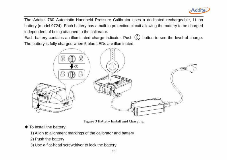
The Additel 760 Automatic Handheld Pressure Calibrator uses a dedicated rechargeable, Li-Ion
battery (model 9724). Each battery has a built-in protection circuit allowing the battery to be charged
independent of being attached to the calibrator.
Each battery contains an illuminated charge indicator. Push button to see the level of charge.
The battery is fully charged when 5 blue LEDs are illuminated.
Figure 3 Battery Install and Charging
◆ To Install the battery:
1) Align to alignment markings of the calibrator and battery
2) Push the battery
3) Use a flat-head screwdriver to lock the battery
19
◆ To Remove the battery:
1) Turn off the calibrator
2) Turn the battery lock to the unlock position with a flat-head screwdriver
3) Remove the battery
◆9816-X External Power Adapter:
1. Input: AC 85V ~ AC 265V, 50Hz / 60Hz
2. Output: DC 10V, 2A, 40W MAX
20
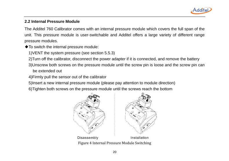
2.2 Internal Pressure Module
The Additel 760 Calibrator comes with an internal pressure module which covers the full span of the
unit. This pressure module is user-switchable and Additel offers a large variety of different range
pressure modules.
◆To switch the internal pressure module:
1)VENT the system pressure (see section 5.5.3)
2)Turn off the calibrator, disconnect the power adapter if it is connected, and remove the battery
3)Unscrew both screws on the pressure module until the screw pin is loose and the screw pin can
be extended out
4)Firmly pull the sensor out of the calibrator
5)Insert a new internal pressure module (please pay attention to module direction)
6)Tighten both screws on the pressure module until the screws reach the bottom
Figure 4 Internal Pressure Module Switching
21
2.3 Starting the Calibrator
Push the power button to turn on the calibrator. The display will illuminate and the Additel logo will
display. It will take a few seconds for the operating system to load after which the main screen will
display.
◆Date and Time: To change date and time setting, please see section 5.7.1
◆Language: The default language is English. To change the language please refer to section 5.7.2
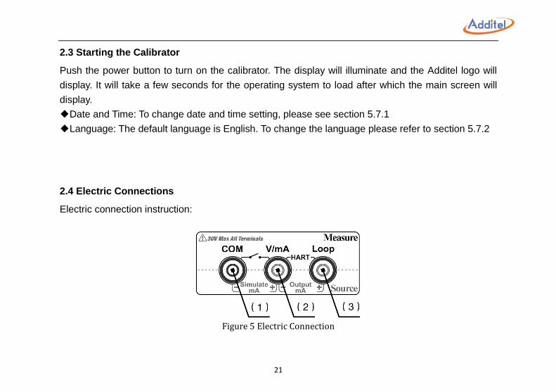
2.4 Electric Connections
Electric connection instruction:
Figure 5 Electric Connection
22
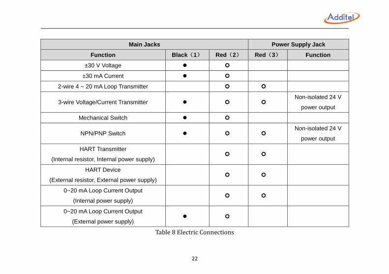
Main Jacks Power Supply Jack
Function Black(1) Red(2) Red(3) Function
±30 V Voltage
±30 mA Current
2-wire 4 ~ 20 mA Loop Transmitter
3-wire Voltage/Current Transmitter Non-isolated 24 V
power output
Mechanical Switch
NPN/PNP Switch Non-isolated 24 V
power output
HART Transmitter
(Internal resistor, Internal power supply)
HART Device
(External resistor, External power supply)
0~20 mA Loop Current Output
(Internal power supply)
0~20 mA Loop Current Output
(External power supply)
Table 8 Electric Connections
23
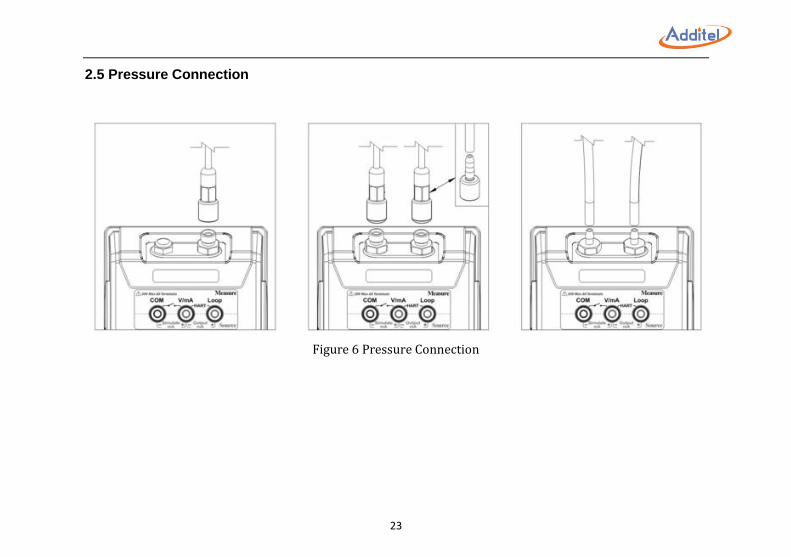
2.5 Pressure Connection
Figure 6 Pressure Connection
24
3. Operation
3.1 Display and Operation
3.1.1 Main Screen
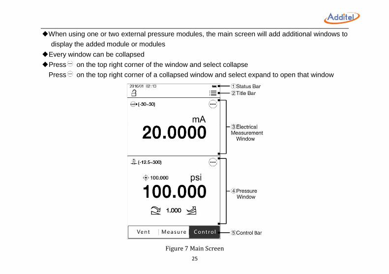
The main screen normally contains the Status Bar, Title Bar, Electrical Measurement Window,
Pressure Window, and Control Bar.
①Status Bar:Includes date and time, external pressure module status , communication status ,
24V internal power status , and battery status .
NOTE: Information on Status Bar is read only. All other icons, pressure units, and output
values can be selected for further operation.
②Title Bar:Includes screen lock , abnormal notification ,and system menu .
◆Abnormal notification sign can be cleared by rebooting the calibrator. Specific information about
the abnormal condition can be reviewed in the system log, please see section 5.5.3.
③Electrical Measurement Window:Includes measurement value, data analysis (current/voltage
measurement and transmitter test only), current output step (current output only), and loop current
value (transmitter test only).
④Pressure Window:Includes pressure set point value , current pressure value, pressure unit, step
control, and step size.
⑤Control Bar:Including Vent, Measure, and Control button.
◆Do not point the VENT port toward personal during venting
25
◆When using one or two external pressure modules, the main screen will add additional windows to
display the added module or modules
◆Every window can be collapsed
◆Press on the top right corner of the window and select collapse
Press on the top right corner of a collapsed window and select expand to open that window
Figure 7 Main Screen
26
3.1.2 Pressure Unit
Press the pressure unit on Pressure Window to change system unit. There are 25 default pressure
units which can be selected: kPa, Pa, MPa, hPa, bar, mbar, torr, atm, psi, gf/cm2, kgf/cm
2,
inH2O@4℃ , inH2O@68℉ , mmH2O@4℃ , mmH2O@20℃ , ftH2O@4℃ , ftH2O@68℉ , inHg@0℃ ,
mmHg@0℃ , mtorr, lb/ft2, tsi, psf, inH2O@60℉ , ftH2O@60℉ .
In addition, there are 5 customizable pressure units which can be set up.
◆ To set up a custom pressure unit:
1) Press in pressure unit selection screen and set up three parameters:
①Factor:This is the multiplier against the reference pressure unit.
②Unit Name:Custom unit name.
③Reference:Reference pressure unit, should be selected from one of the 25 default pressure
units.
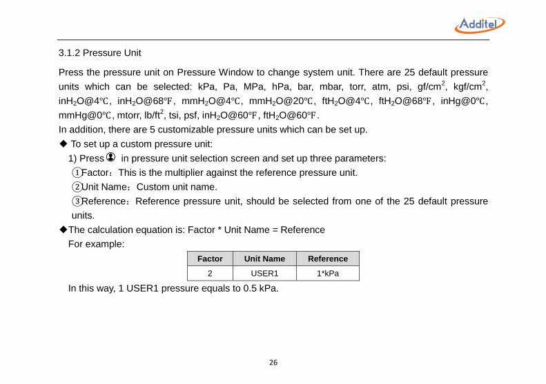
◆The calculation equation is: Factor * Unit Name = Reference
For example:
Factor Unit Name Reference
2 USER1 1*kPa
In this way, 1 USER1 pressure equals to 0.5 kPa.
27
3.1.3 Pressure Output
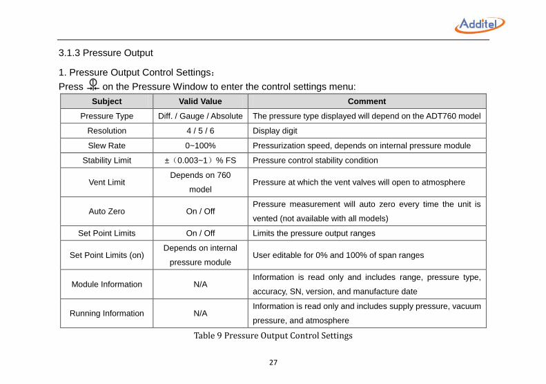
1. Pressure Output Control Settings:
Press on the Pressure Window to enter the control settings menu:
Subject Valid Value Comment
Pressure Type Diff. / Gauge / Absolute The pressure type displayed will depend on the ADT760 model
Resolution 4 / 5 / 6 Display digit
Slew Rate 0~100% Pressurization speed, depends on internal pressure module
Stability Limit ±(0.003~1)% FS Pressure control stability condition
Vent Limit Depends on 760
model Pressure at which the vent valves will open to atmosphere
Auto Zero On / Off Pressure measurement will auto zero every time the unit is
vented (not available with all models)
Set Point Limits On / Off Limits the pressure output ranges
Set Point Limits (on) Depends on internal
pressure module User editable for 0% and 100% of span ranges
Module Information N/A Information is read only and includes range, pressure type,
accuracy, SN, version, and manufacture date
Running Information N/A Information is read only and includes supply pressure, vacuum
pressure, and atmosphere
Table 9 Pressure Output Control Settings
28
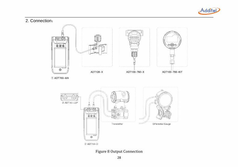
2. Connection:
Figure 8 Output Connection
29
3. Pressure Set Point:
①Manual Input:
1)Press pressure set point value or current pressure value on the Pressure Window and input the
target pressure.
2)Press the enter key or .
NOTE: Pressure set point should not exceed pressure range limit shown above the keyboard.
②Manual Step:
1)Press step size on the Pressure Window and input the target step size.
2)Press to decrease or increase pressure by the target step size.
30
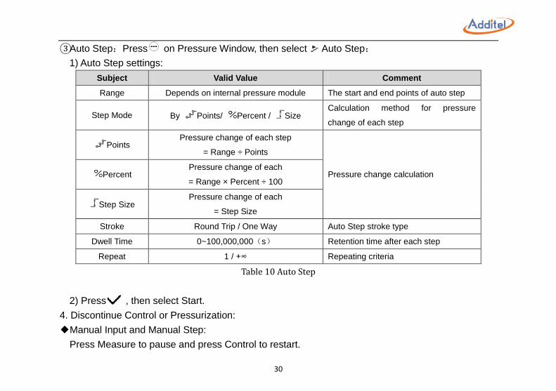
③Auto Step:Press on Pressure Window, then select Auto Step:
1) Auto Step settings:
Subject Valid Value Comment
Range Depends on internal pressure module The start and end points of auto step
Step Mode By Points/ Percent / Size Calculation method for pressure
change of each step
Points Pressure change of each step
= Range ÷ Points
Pressure change calculation Percent Pressure change of each
= Range × Percent ÷ 100
Step Size Pressure change of each
= Step Size
Stroke Round Trip / One Way Auto Step stroke type
Dwell Time 0~100,000,000(s) Retention time after each step
Repeat 1 / +∞ Repeating criteria
Table 10 Auto Step
2) Press , then select Start.
4. Discontinue Control or Pressurization:
◆Manual Input and Manual Step:
Press Measure to pause and press Control to restart.
31
Press Vent and the pressure will decrease and release.
◆Auto Step:
Press Pause to pause.
Press Exit to exit and the calibrator will release the pressure.
Press Vent to release the pressure then press Exit to stop the test or Continue to resume the test.
5. Pressure Stabilization:
If the difference between current output pressure value and set point is smaller than Stability Limit,
the current pressure value on the Pressure Window will turn to green with a beep to indicate the
output pressure has reached the set point stability criteria.
32
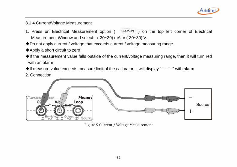
3.1.4 Current/Voltage Measurement
1. Press on Electrical Measurement option ( ) on the top left corner of Electrical
Measurement Window and select:(-30~30) mA or (-30~30) V.
◆Do not apply current / voltage that exceeds current / voltage measuring range
◆Apply a short circuit to zero
◆If the measurement value falls outside of the current/voltage measuring range, then it will turn red
with an alarm
◆If measure value exceeds measure limit of the calibrator, it will display "--------" with alarm
2. Connection
Figure 9 Current / Voltage Measurement
33
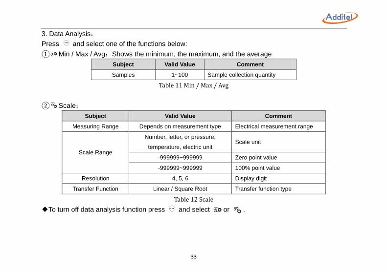
3. Data Analysis:
Press and select one of the functions below:
① Min / Max / Avg:Shows the minimum, the maximum, and the average
Subject Valid Value Comment
Samples 1~100 Sample collection quantity
Table 11 Min / Max / Avg
② Scale:
Subject Valid Value Comment
Measuring Range Depends on measurement type Electrical measurement range
Scale Range
Number, letter, or pressure,
temperature, electric unit Scale unit
-999999~999999 Zero point value
-999999~999999 100% point value
Resolution 4, 5, 6 Display digit
Transfer Function Linear / Square Root Transfer function type
Table 12 Scale
◆To turn off data analysis function press and select or .
34
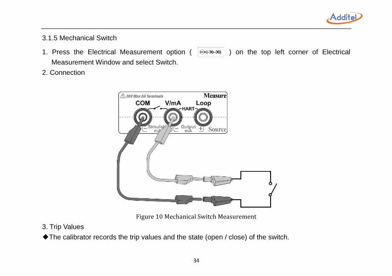
3.1.5 Mechanical Switch
1. Press the Electrical Measurement option ( ) on the top left corner of Electrical
Measurement Window and select Switch.
2. Connection
Figure 10 Mechanical Switch Measurement
3. Trip Values
◆The calibrator records the trip values and the state (open / close) of the switch.
35
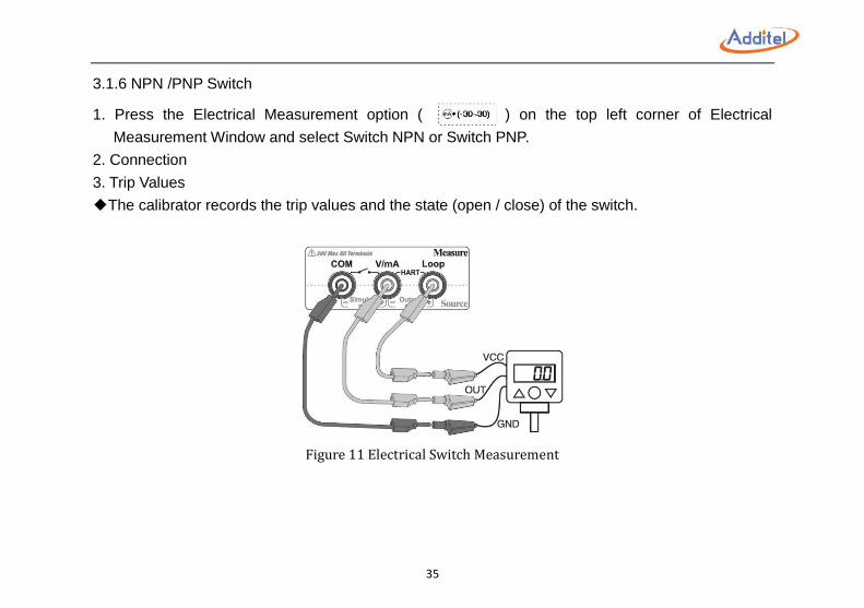
3.1.6 NPN /PNP Switch
1. Press the Electrical Measurement option ( ) on the top left corner of Electrical
Measurement Window and select Switch NPN or Switch PNP.
2. Connection
3. Trip Values
◆The calibrator records the trip values and the state (open / close) of the switch.
Figure 11 Electrical Switch Measurement
36
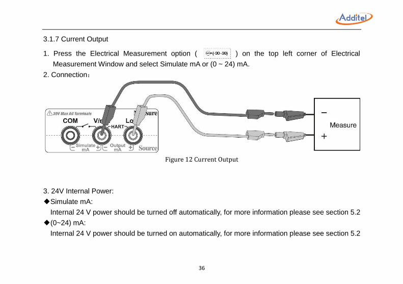
3.1.7 Current Output
1. Press the Electrical Measurement option ( ) on the top left corner of Electrical
Measurement Window and select Simulate mA or (0 ~ 24) mA.
2. Connection:
Figure 12 Current Output
3. 24V Internal Power:
◆Simulate mA:
Internal 24 V power should be turned off automatically, for more information please see section 5.2
◆(0~24) mA:
Internal 24 V power should be turned on automatically, for more information please see section 5.2
37
4. Current Set Point:
①Manual Input:
1)Click Measure Value on the Electrical Measurement Window, and input the target value
2)Press .
②Manual Step:
1)Press step size on the Electrical Measurement Window and input the current output range
2)Press / each time to decrease or increase current output by 25% of range
NOTE: Current output range shall not exceed 0~24 mA.
38
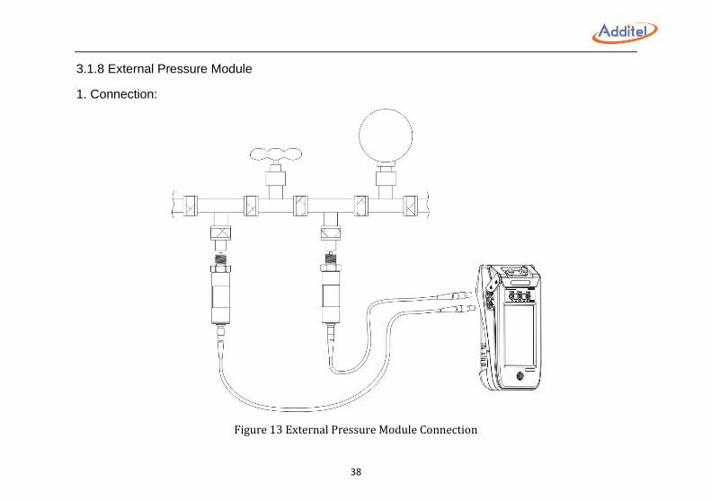
3.1.8 External Pressure Module
1. Connection:
Figure 13 External Pressure Module Connection
39
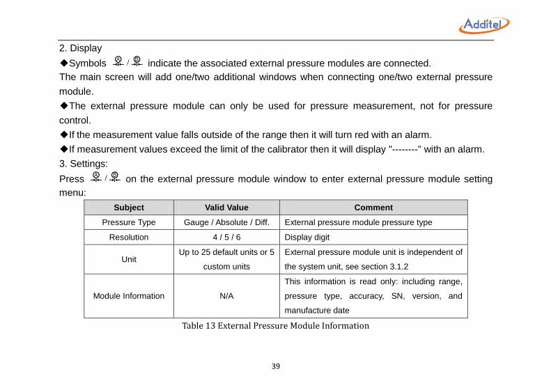
2. Display
◆Symbols indicate the associated external pressure modules are connected.
The main screen will add one/two additional windows when connecting one/two external pressure
module.
◆The external pressure module can only be used for pressure measurement, not for pressure
control.
◆If the measurement value falls outside of the range then it will turn red with an alarm.
◆If measurement values exceed the limit of the calibrator then it will display "--------" with an alarm.
3. Settings:
Press on the external pressure module window to enter external pressure module setting
menu:
Subject Valid Value Comment
Pressure Type Gauge / Absolute / Diff. External pressure module pressure type
Resolution 4 / 5 / 6 Display digit
Unit Up to 25 default units or 5
custom units
External pressure module unit is independent of
the system unit, see section 3.1.2
Module Information N/A
This information is read only: including range,
pressure type, accuracy, SN, version, and
manufacture date
Table 13 External Pressure Module Information
40
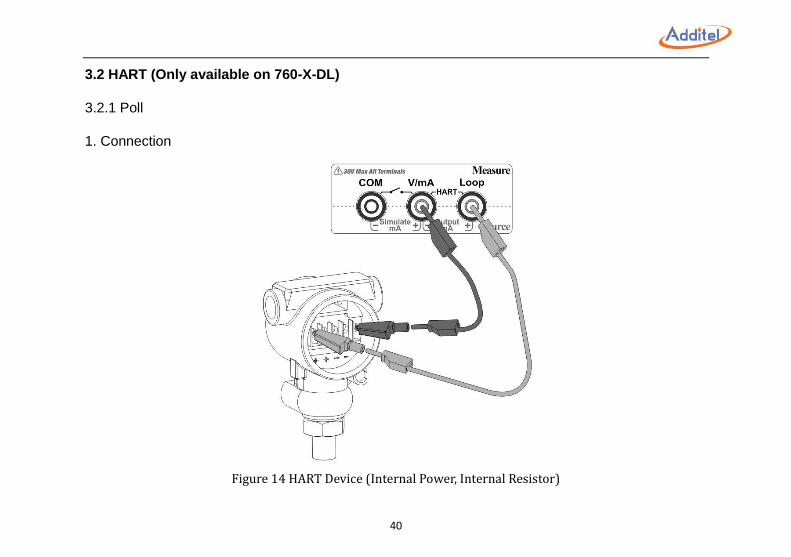
3.2 HART (Only available on 760-X-DL)
3.2.1 Poll
1. Connection
Figure 14 HART Device (Internal Power, Internal Resistor)
41
Figure 15 HART Device (External Power, External Resistor)
2. HART Device Type Selection:
On top of Electrical Measurement Window please press (or ) and select:
1). Internal Power and Resistor
2). External Power and Resistor
42
2. Search
1) Poll
Press on Electrical Measurement option ( ) on the top left corner of the Electrical
Measurement Window and select HART. The calibrator will poll address 0 if no connection detected.
Then it will scan addresses 1 to 15 automatically.
2) Manual Search
HART device manual search is available if necessary.
1)Press on Electrical Measurement Window, then select Search. The calibrator will list all
HART device detected.
2)Select the device which needs to be tested. If still no required HART device are detected then
press to scan address from 1 to 15 automatically.
3.2.2 Operation Window
The HART measurement value will display on the Electrical Measurement Window. Other process
variables can be displayed, see section 3.2.5. Loop current and HART device name are displayed on
the bottom of the window.
◆Press the pressure unit to change HART device pressure measuring unit
◆Changing HART device pressure measure unit will not change the calibrator system unit
43
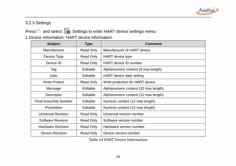
3.2.3 Settings
Press and select Settings to enter HART device settings menu:
1.Device Information: HART device information
Subject Type Comment
Manufacturer Read Only Manufacturer of HART device
Device Type Read Only HART device type
Device ID Read Only HART device ID number
Tag Editable Alphanumeric content (8 max length)
Date Editable HART device date setting
Write Protect Read Only Write protection for HART device
Message Editable Alphanumeric content (32 max length)
Descriptor Editable Alphanumeric content (12 max length)
Final Assembly Number Editable Numeric content (12 max length)
Preambles Editable Numeric content (12 max length)
Universal Revision Read Only Universal version number
Software Revision Read Only Software version number
Hardware Revision Read Only Hardware version number
Device Revision Read Only Device version number
Table 14 HART Device Information
44
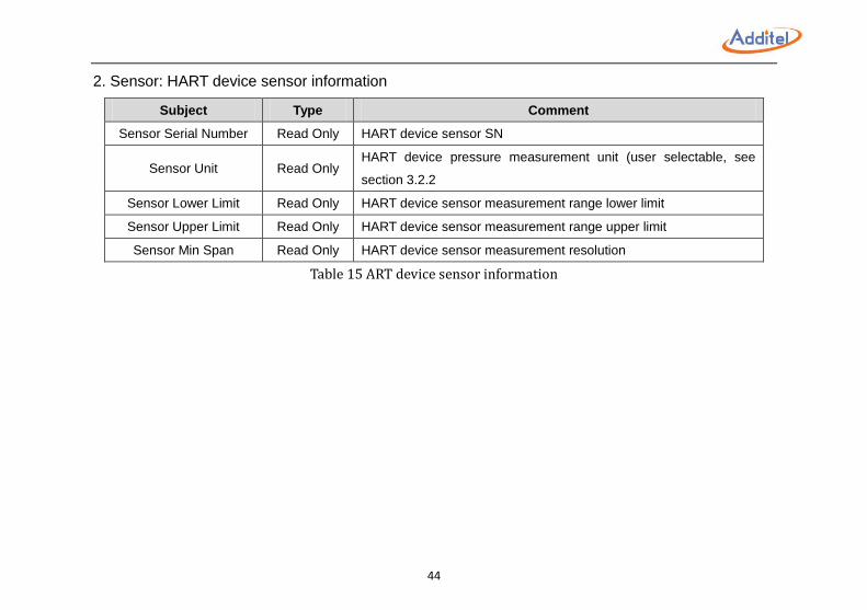
2. Sensor: HART device sensor information
Subject Type Comment
Sensor Serial Number Read Only HART device sensor SN
Sensor Unit Read Only HART device pressure measurement unit (user selectable, see
section 3.2.2
Sensor Lower Limit Read Only HART device sensor measurement range lower limit
Sensor Upper Limit Read Only HART device sensor measurement range upper limit
Sensor Min Span Read Only HART device sensor measurement resolution
Table 15 ART device sensor information
45
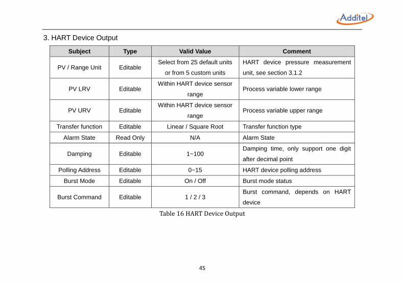
3. HART Device Output
Subject Type Valid Value Comment
PV / Range Unit Editable Select from 25 default units
or from 5 custom units
HART device pressure measurement
unit, see section 3.1.2
PV LRV Editable Within HART device sensor
range Process variable lower range
PV URV Editable Within HART device sensor
range Process variable upper range
Transfer function Editable Linear / Square Root Transfer function type
Alarm State Read Only N/A Alarm State
Damping Editable 1~100 Damping time, only support one digit
after decimal point
Polling Address Editable 0~15 HART device polling address
Burst Mode Editable On / Off Burst mode status
Burst Command Editable 1 / 2 / 3 Burst command, depends on HART
device
Table 16 HART Device Output
46
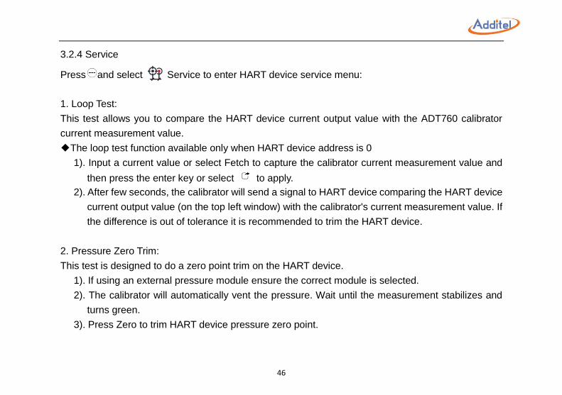
3.2.4 Service
Press and select Service to enter HART device service menu:
1. Loop Test:
This test allows you to compare the HART device current output value with the ADT760 calibrator
current measurement value.
◆The loop test function available only when HART device address is 0
1). Input a current value or select Fetch to capture the calibrator current measurement value and
then press the enter key or select to apply.
2). After few seconds, the calibrator will send a signal to HART device comparing the HART device
current output value (on the top left window) with the calibrator's current measurement value. If
the difference is out of tolerance it is recommended to trim the HART device.
2. Pressure Zero Trim:
This test is designed to do a zero point trim on the HART device.
1). If using an external pressure module ensure the correct module is selected.
2). The calibrator will automatically vent the pressure. Wait until the measurement stabilizes and
turns green.
3). Press Zero to trim HART device pressure zero point.
47
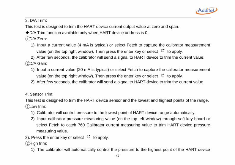
3. D/A Trim:
This test is designed to trim the HART device current output value at zero and span.
◆D/A Trim function available only when HART device address is 0.
①D/A Zero:
1). Input a current value (4 mA is typical) or select Fetch to capture the calibrator measurement
value (on the top right window). Then press the enter key or select to apply.
2). After few seconds, the calibrator will send a signal to HART device to trim the current value.
②D/A Gain:
1). Input a current value (20 mA is typical) or select Fetch to capture the calibrator measurement
value (on the top right window). Then press the enter key or select to apply.
2). After few seconds, the calibrator will send a signal to HART device to trim the current value.
4. Sensor Trim:
This test is designed to trim the HART device sensor and the lowest and highest points of the range.
①Low trim:
1). Calibrator will control pressure to the lowest point of HART device range automatically.
2). Input calibrator pressure measuring value (on the top left window) through soft key board or
select Fetch to catch 760 Calibrator current measuring value to trim HART device pressure
measuring value.
3). Press the enter key or select to apply.
②High trim:
1). The calibrator will automatically control the pressure to the highest point of the HART device
48
range.
2). Input the calibrator pressure measurement value (on the top left window) or select Fetch to
capture the calibrator value to trim the HART device.
3). Press the enter key or select to apply.
③Trim Reset:
This feature will reset the HART device back to factory parameters.
49
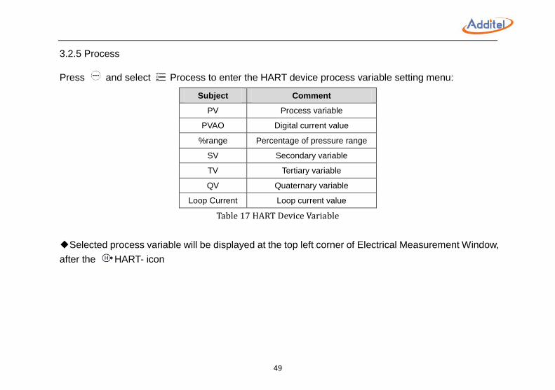
3.2.5 Process
Press and select Process to enter the HART device process variable setting menu:
Subject Comment
PV Process variable
PVAO Digital current value
%range Percentage of pressure range
SV Secondary variable
TV Tertiary variable
QV Quaternary variable
Loop Current Loop current value
Table 17 HART Device Variable
◆Selected process variable will be displayed at the top left corner of Electrical Measurement Window,
after the HART- icon
50
3.3 Zeroing
The zeroing function is available for current/voltage measurement and pressure measurement either
internal or external pressure modules.
◆To zero: Press and select
◆Apply a short circuit for current / voltage zeroing
◆Allowable zeroing range:
Pressure: within 1%FS;
Current / Voltage: within 0.1%FS.
3.4 Vent
Press Vent on Control Bar and the calibrator will run the vent process.
◆The vent process will end pressurization during a regular test, typical application, task, and leak
test
◆The VENT port should not face the operator during venting process
◆Dust or contaminants may blow out through the VENT port
◆Any moisture or liquid may also blow out through the vent port
51
4. Typical Applications The Additel 760 Automatic Handheld Pressure Calibrator supports six typical applications.
To start, please select Calibrator under Main Menu , then select the desired application.
◆In the operation interface, press to re-select from the application list
◆In the operation interface, press to enter the new test set up
◆Zeroing:If current / voltage measurement or internal pressure module requires zeroing then press
and select to zero the measurement, see section 3.3
◆Custom applications can be built with several simple selections
52
4.1 Pressure Gauge (Includes dial and digital pressure gauges)
In pressure gauge mode, pressure is the only output function available.
1. Pressure Output
◆Ensure proper pressure connections
◆ For pressure output, please see section 3.1.3
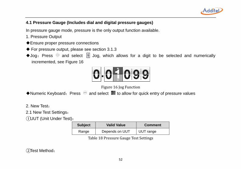
◆Jog:Press and select Jog, which allows for a digit to be selected and numerically
incremented, see Figure 16
Figure 16 Jog Function
◆Numeric Keyboard:Press and select to allow for quick entry of pressure values
2. New Test:
2.1 New Test Settings:
①UUT (Unit Under Test):
Subject Valid Value Comment
Range Depends on UUT UUT range
Table 18 Pressure Gauge Test Settings
②Test Method:
53
See section 3.1.3-3-③Auto Step.
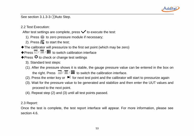
2.2 Test Execution:
After test settings are complete, press to execute the test:
1). Press to zero pressure module if necessary;
2). Press to start the test;
◆The calibrator will pressurize to the first set point (which may be zero)
◆Press to switch calibration interface
◆Press to check or change test settings
3). Standard test steps:
(1). After the pressure shows it is stable, the gauge pressure value can be entered in the box on
the right. Press to switch the calibration interface.
(2). Press the enter key or for next test point and the calibrator will start to pressurize again
(3). Wait for the pressure value to be generated and stabilize and then enter the UUT values and
proceed to the next point.
(4). Repeat step (2) and (3) until all test points passed.
2.3 Report:
Once the test is complete, the test report interface will appear. For more information, please see
section 4.6.
54
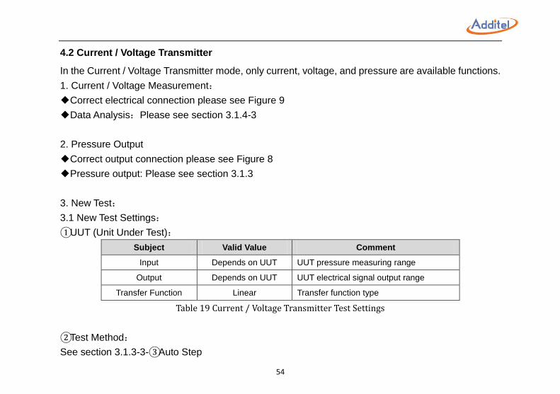
4.2 Current / Voltage Transmitter
In the Current / Voltage Transmitter mode, only current, voltage, and pressure are available functions.
1. Current / Voltage Measurement:
◆Correct electrical connection please see Figure 9
◆Data Analysis:Please see section 3.1.4-3
2. Pressure Output
◆Correct output connection please see Figure 8
◆Pressure output: Please see section 3.1.3
3. New Test:
3.1 New Test Settings:
①UUT (Unit Under Test):
Subject Valid Value Comment
Input Depends on UUT UUT pressure measuring range
Output Depends on UUT UUT electrical signal output range
Transfer Function Linear Transfer function type
Table 19 Current / Voltage Transmitter Test Settings
②Test Method:
See section 3.1.3-3-③Auto Step
55
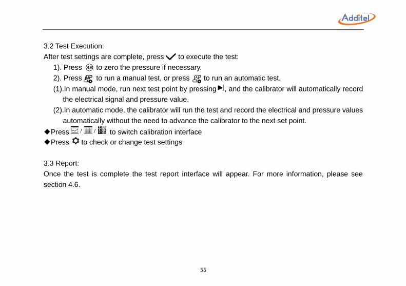
3.2 Test Execution:
After test settings are complete, press to execute the test:
1). Press to zero the pressure if necessary.
2). Press to run a manual test, or press to run an automatic test.
(1).In manual mode, run next test point by pressing , and the calibrator will automatically record
the electrical signal and pressure value.
(2).In automatic mode, the calibrator will run the test and record the electrical and pressure values
automatically without the need to advance the calibrator to the next set point.
◆Press to switch calibration interface
◆Press to check or change test settings
3.3 Report:
Once the test is complete the test report interface will appear. For more information, please see
section 4.6.

56
4.3 HART Transmitter
In HART Transmitter mode, only the Process Variable function and the Pressure function are
available.
1. HART Function:
◆Correct electrical connection and HART function, please see section 3.2
2. Pressure Output:
◆Correct output connection please see Figure 8
◆Pressure output: Please see section 3.1.3
3. New Test:
3.1 New Test Settings:
①UUT (Unit Under Test):
Subject Valid Value Comment
Input Depends on UUT UUT pressure measuring range
Transfer Function Linear / Square Root Transfer function type
Table 20 HART Device Test Settings
②Test Method:
See section 3.1.3-3-③Auto Step
3.2 Test Execution:
After test settings are complete, press to execute the test:

57
1).Press to zero the pressure if necessary.
2).Press to run a manual test, or press to run a automatic test.
(1).In manual mode, run the next test point by press calibrator and the calibrator will
automatically record the electrical signal and pressure value.
(2).In automatic mode, the calibrator will run the test and record the electrical and pressure values
automatically without the need to advance the calibrator to the next set point.
◆Press to switch calibration interface
◆Press to check or change test settings
3.3 Report:
Once the test is complete the test report interface will appear. For more information, please see
section 4.6.
58
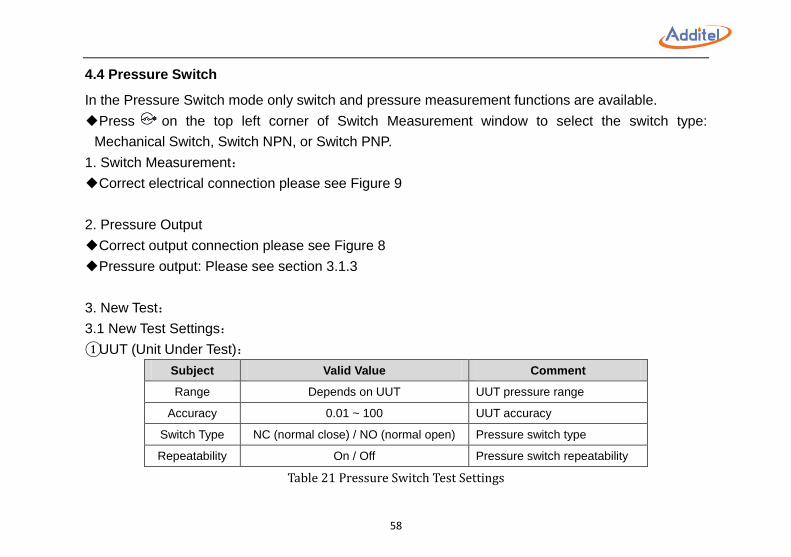
4.4 Pressure Switch
In the Pressure Switch mode only switch and pressure measurement functions are available.
◆Press on the top left corner of Switch Measurement window to select the switch type:
Mechanical Switch, Switch NPN, or Switch PNP.
1. Switch Measurement:
◆Correct electrical connection please see Figure 9
2. Pressure Output
◆Correct output connection please see Figure 8
◆Pressure output: Please see section 3.1.3
3. New Test:
3.1 New Test Settings:
①UUT (Unit Under Test):
Subject Valid Value Comment
Range Depends on UUT UUT pressure range
Accuracy 0.01 ~ 100 UUT accuracy
Switch Type NC (normal close) / NO (normal open) Pressure switch type
Repeatability On / Off Pressure switch repeatability
Table 21 Pressure Switch Test Settings
59
3.2 Test Execution:
After test settings are complete, press to execute the test:
1). Press to run test automatically
◆Press to check or change test settings
3.3 Report:
Once the test is complete the test report interface will appear. For more information, please see
section 4.6.
60
4.5 I/P Converter
In the I/P Converter mode only pressure and current functions are available.
◆Press on the top left corner of Current Output window to select the switch type: (0~24) or
Simulate mA.
1. Pressure Output
◆Correct output connection please see Figure 8
◆Do not exceed the pressure range of the calibrator
◆Please select Measure on Control Bar
2. Current Output:
◆Correct electrical connection and Current Output function, please see section 3.1.7
◆Jog:Press and select Jog, current output value could be adjusted by each digit in this
mode, see Figure 16
◆Scale:Press and select Scale for scale function, more detail please see section 3.14-3-②
3. New Test:
3.1 New Test Settings:
①UUT (Unit Under Test):
61
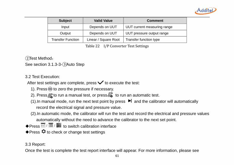
Subject Valid Value Comment
Input Depends on UUT UUT current measuring range
Output Depends on UUT UUT pressure output range
Transfer Function Linear / Square Root Transfer function type
Table 22 I/P Converter Test Settings
②Test Method:
See section 3.1.3-3-③Auto Step
3.2 Test Execution:
After test settings are complete, press to execute the test:
1). Press to zero the pressure if necessary.
2). Press to run a manual test, or press to run an automatic test.
(1).In manual mode, run the next test point by press and the calibrator will automatically
record the electrical signal and pressure value.
(2).In automatic mode, the calibrator will run the test and record the electrical and pressure values
automatically without the need to advance the calibrator to the next set point.
◆Press to switch calibration interface
◆Press to check or change test settings
3.3 Report:
Once the test is complete the test report interface will appear. For more information, please see
62
section 4.6.
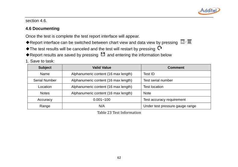
4.6 Documenting
Once the test is complete the test report interface will appear.
◆Report interface can be switched between chart view and data view by pressing
◆The test results will be canceled and the test will restart by pressing
◆Report results are saved by pressing and entering the information below
1. Save to task:
Subject Valid Value Comment
Name Alphanumeric content (16 max length) Test ID
Serial Number Alphanumeric content (16 max length) Test serial number
Location Alphanumeric content (16 max length) Test location
Notes Alphanumeric content (16 max length) Note
Accuracy 0.001~100 Test accuracy requirement
Range N/A Under test pressure gauge range
Table 23 Test Information
63
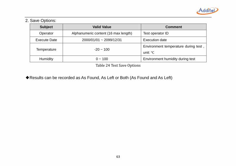
2. Save Options:
Subject Valid Value Comment
Operator Alphanumeric content (16 max length) Test operator ID
Execute Date 2000/01/01 ~ 2099/12/31 Execution date
Temperature -20 ~ 100 Environment temperature during test ,
unit: ℃
Humidity 0 ~ 100 Environment humidity during test
Table 24 Test Save Options
◆Results can be recorded as As Found, As Left or Both (As Found and As Left)
64
5. Setup To enter the setup menu, please select Setup under Main Menu .
◆Any changes made in the Setup will become the default values after the calibrator is rebooted.
5.1 Control Settings
See section 3.1.3-1
5.2 24V Power
To turn on or turn off internal 24V power supply.
◆For safety and operation convenience, 24V power will be turned on or off automatically depending
on the calibration operation.
65
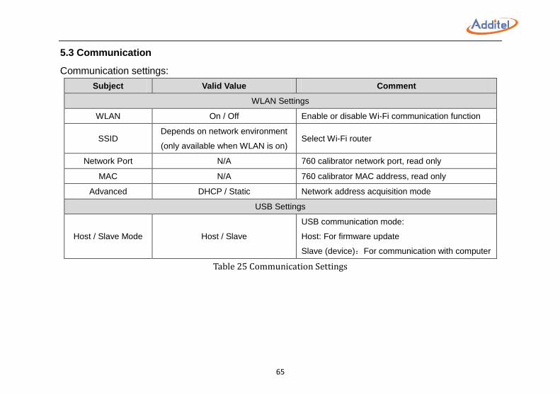
5.3 Communication
Communication settings:
Subject Valid Value Comment
WLAN Settings
WLAN On / Off Enable or disable Wi-Fi communication function
SSID Depends on network environment
(only available when WLAN is on) Select Wi-Fi router
Network Port N/A 760 calibrator network port, read only
MAC N/A 760 calibrator MAC address, read only
Advanced DHCP / Static Network address acquisition mode
USB Settings
Host / Slave Mode Host / Slave
USB communication mode:
Host: For firmware update
Slave (device):For communication with computer
Table 25 Communication Settings
66
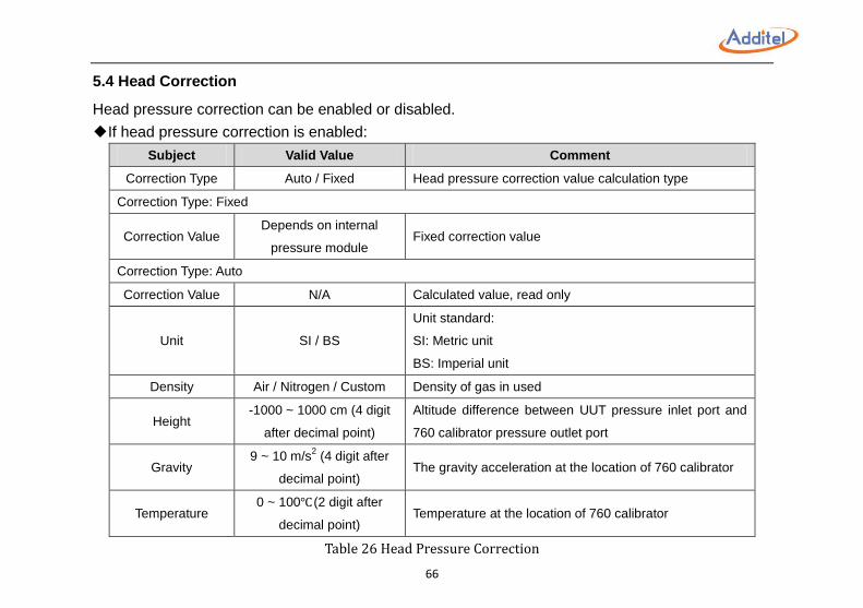
5.4 Head Correction
Head pressure correction can be enabled or disabled.
◆If head pressure correction is enabled:
Subject Valid Value Comment
Correction Type Auto / Fixed Head pressure correction value calculation type
Correction Type: Fixed
Correction Value Depends on internal
pressure module Fixed correction value
Correction Type: Auto
Correction Value N/A Calculated value, read only
Unit SI / BS
Unit standard:
SI: Metric unit
BS: Imperial unit
Density Air / Nitrogen / Custom Density of gas in used
Height -1000 ~ 1000 cm (4 digit
after decimal point)
Altitude difference between UUT pressure inlet port and
760 calibrator pressure outlet port
Gravity 9 ~ 10 m/s
2 (4 digit after
decimal point) The gravity acceleration at the location of 760 calibrator
Temperature 0 ~ 100℃ (2 digit after
decimal point) Temperature at the location of 760 calibrator
Table 26 Head Pressure Correction
67
NOTE: Default air and nitrogen density is 0°C @ 1 013,25 hPa. After inputting your height and
temperature the ADT760 will calculate the correction value.
5.5 Services
5.5.1 Calibration
To calibrate 760 calibrator system.
CAUTIONS:
◆The calibrator should be powered to warm up 30 minutes prior to starting the calibration
◆Current / voltage measurement, current output, and internal pressure module need to be calibrated periodically
◆Carefully read user manual and follow the instruction before 760 calibrator system calibration operation
◆Incorrect system calibration operation will decrease the accuracy of 760 calibrator, even shutting down
◆During system calibration operation, pressing will restore the factory calibration and change the calibration
date to "----/--/--"
◆A higher accuracy standard should be used to calibrate the ADT760 calibrator
◆The calibration operation password is: 123456
◆Once the calibration is completed and saved the new data will be immediately loaded and used. A new
calibration date will also be uploaded
◆Once a new calibration has been finished and saved any previous calibrations will be permanently deleted
except for the factory calibration
68
5.5.1.1 Current / Voltage Measurement Calibration
1. Connection:
◆Correct electrical connection please see Figure 9
2. Calibration point setup:
Select the calibration point which needs to be changed, then input value
◆3 points for current / voltage measurement calibration
◆Default current measurement calibration points are -30 mA, 0 mA, 30 mA
Default voltage measurement calibration points are -30 V, 0 V, 30 V
◆Additel does not recommend changing calibration points.
3. Calibration Execution:
1). Press to start calibration process
2). Output current / voltage from standard to 760 calibrator and the standard output value needs to
be the same as the corresponding calibration set point
3). When Measured Value is stable, press to record data and move to the next calibration
point
◆If the difference between Calibration Point and Measured Value is unacceptable, the Measured
Value will display red.
5.5.1.2 Current Output Calibration
1. Connection:
◆Correct electrical connection please see Figure 3-3.
2. Calibration point setup:
69
Select the calibration point which needs to be changed, then input value
◆3 points for current output calibration
◆Default current output calibration points are 1mA, 10mA, 20mA
◆Additel does not recommend changing calibration points.
3. Calibration Execution:
1). Press to start calibration process
2). Output current from 760 calibrator to standard
3). When standard measuring value is stable, press correspondent Measured Value and input
measuring value displayed on the standard then select Enter button or to confirm and then
press to record data and move to the next calibration point.
5.5.1.3 Internal Pressure Module Calibration
1. Output Connection:
Select Internal / External pressurizing;
◆For Internal pressurizing: Please connect 760 calibrator pressure outlet port to the standard
ensuring the standard is in measurement mode
◆For External pressurizing: Please connect 760 calibrator pressure outlet port with the standard,
ensuring the standard is in pressure generation mode
2. Calibration point setup:
Select the calibration point which needs to be changed, then input value
◆3 points for internal pressure module calibration
◆Default calibration points are the lower limit, zero point, and the upper limit of internal pressure
70
module
◆Additel does not recommend changing calibration points
NOTE: The lower limit of some internal pressure modules may exceed the lower limit of 760
calibrator pump, please use External pressurizing to calibrate these internal pressure
modules.
3. Calibration Execution:
1). Press to start calibration process
2). Pressurization:
①Internal pressurizing:
Generate pressure using the 760 internal pump. When the pressure is stable press Reference
value and input the value and select the Enter key or to confirm, then press to record
data and move to the next calibration point.
②External pressurizing:
Output pressure from standard to 760 calibrator, and not the standard output value shall be the
same as correspondent calibration set point. When Measured Value is stable, press to record
data and move to the next calibration point.
5.5.1.4 Auto Tune
This function is only used during when recommended by Additel Corporation to service the calibrator
5.5.1.5 Pressure Sensor
This function is for positive and negative pressure sensor check with atmosphere.
71
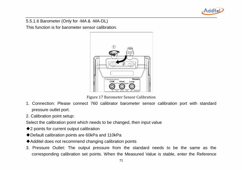
5.5.1.6 Barometer (Only for -MA & -MA-DL)
This function is for barometer sensor calibration.
Figure 17 Barometer Sensor Calibration
1. Connection: Please connect 760 calibrator barometer sensor calibration port with standard
pressure outlet port.
2. Calibration point setup:
Select the calibration point which needs to be changed, then input value
◆2 points for current output calibration
◆Default calibration points are 60kPa and 110kPa
◆Additel does not recommend changing calibration points
3. Pressure Outlet: The output pressure from the standard needs to be the same as the
corresponding calibration set points. When the Measured Value is stable, enter the Reference
72
value displayed on the standard and press the Enter key or to confirm, then press to
record data and move to the next calibration point.
5.5.1.7 Touch Screen
To check the touch screen, please press the center of black cross displayed on the screen five times.
◆If pressed on the deviation from the center of black cross, the test will repeat until it is precisely
pressed five times on the center of the black cross.
5.5.2 Diagnosis
This menu provides diagnostic information from the main board, control board, and electrical board
which may help indicate if anything is working improperly.
◆If a problem is detected then please contact Additel for further assistance
◆More information:
1. Password: 123456
5.5.3 System Log
Lists all abnormal information. Powering off or rebooting will not clear the information. The information
can be cleared by an update, please see section 5.5.4, or factory reset, please see section 5.5.5.
73
5.5.4 Maintenance
This menu is used to depressurize the unit when switching internal pressure models.
◆Press to start.
5.5.5 Factory Reset
Resets all data to factory default settings.
◆Password:123456
5.5.6 Updates
To update 760 calibrator firmware, please:
1). Copy update file into an USB root directory
2). Insert USB into 760 calibrator USB port
3). Select Updates by USB on calibrator
4). Wait for the update to complete in which a notification will be given
◆Password:123456
◆The USB has to be in FAT16 or FAT32 type
◆The calibrator will switch USB port to Host type automatically
74
5.6 Sound
To enable or disable Touch Beep and Over range alarm beep.
5.7 Personalization
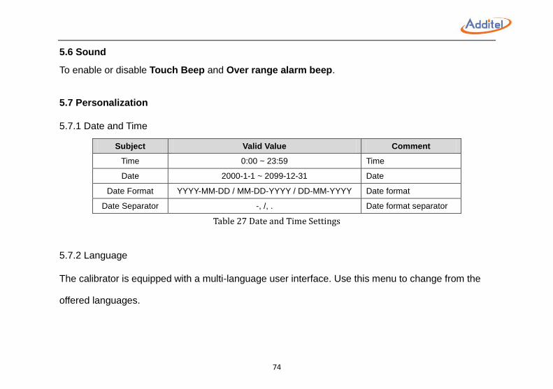
5.7.1 Date and Time
Subject Valid Value Comment
Time 0:00 ~ 23:59 Time
Date 2000-1-1 ~ 2099-12-31 Date
Date Format YYYY-MM-DD / MM-DD-YYYY / DD-MM-YYYY Date format
Date Separator -, /, . Date format separator
Table 27 Date and Time Settings
5.7.2 Language
The calibrator is equipped with a multi-language user interface. Use this menu to change from the
offered languages.
75
5.7.3 Theme
Switch to Light Theme or Dark Theme.
5.7.4 Safety Data
Switch ON/OFF a warning before data deletion.
5.8 Power Management
Subject Valid Value Comment
Brightness 1~100% Adjusting this setting may impact the battery life.
Battery Info N/A
Battery Information: remaining capacity, full capacity,
temperature, voltage, cell voltage I & II, Charging /
Discharging Current
Auto Backlight Off Never, 15 sec, 30 sec, 1
min, 5 min, 15 min, 30 min Touch the screen to turn the backlight on
Auto Off Never, 5 min, 15 min, 30
min, 1 hour, 2 hour
Auto power off after backlight is turned off. There will
be a 30s countdown
Table 28 Power Management
76
5.9 System Information
1. Main:
Main information of 760 calibrator: including serial number, application, system version, Wi-Fi, BLE
(Bluetooth), control board, electric board information
2. Battery:
Battery information: including serial number, version, manufacture date information.
3. Internal module:
Internal pressure module information: including range, pressure type, accuracy, serial number,
version, manufacture date information.
77
6. Task (Only available on 760-X-DL) The Additel 760 calibrator provides task functionality for automated calibration while storing and
archiving the calibration data. To use the task function, please select Task under Main Menu
6.1 New Task
Press and select UUT (Unit Under Test) type to enter a New Task interface and add UUT
information.
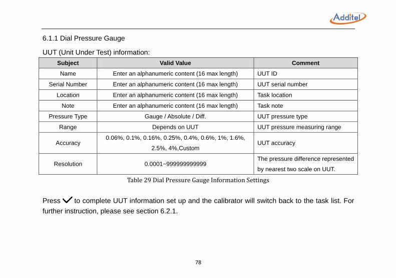
78
6.1.1 Dial Pressure Gauge
UUT (Unit Under Test) information:
Subject Valid Value Comment
Name Enter an alphanumeric content (16 max length) UUT ID
Serial Number Enter an alphanumeric content (16 max length) UUT serial number
Location Enter an alphanumeric content (16 max length) Task location
Note Enter an alphanumeric content (16 max length) Task note
Pressure Type Gauge / Absolute / Diff. UUT pressure type
Range Depends on UUT UUT pressure measuring range
Accuracy 0.06%, 0.1%, 0.16%, 0.25%, 0.4%, 0.6%, 1%, 1.6%,
2.5%, 4%,Custom UUT accuracy
Resolution 0.0001~999999999999 The pressure difference represented
by nearest two scale on UUT.
Table 29 Dial Pressure Gauge Information Settings
Press to complete UUT information set up and the calibrator will switch back to the task list. For
further instruction, please see section 6.2.1.
79
6.1.2 Digital Pressure Gauge
Please see section 6.1.1.
Press to complete UUT information set up and the calibrator will switch back to the task list. For
further instruction, please see section 6.2.2.
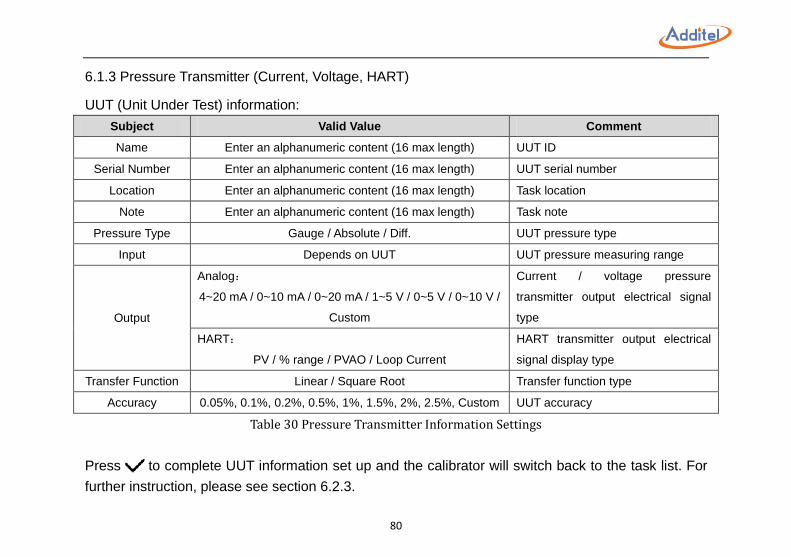
80
6.1.3 Pressure Transmitter (Current, Voltage, HART)
UUT (Unit Under Test) information:
Subject Valid Value Comment
Name Enter an alphanumeric content (16 max length) UUT ID
Serial Number Enter an alphanumeric content (16 max length) UUT serial number
Location Enter an alphanumeric content (16 max length) Task location
Note Enter an alphanumeric content (16 max length) Task note
Pressure Type Gauge / Absolute / Diff. UUT pressure type
Input Depends on UUT UUT pressure measuring range
Output
Analog:
4~20 mA / 0~10 mA / 0~20 mA / 1~5 V / 0~5 V / 0~10 V /
Custom
Current / voltage pressure
transmitter output electrical signal
type
HART:
PV / % range / PVAO / Loop Current
HART transmitter output electrical
signal display type
Transfer Function Linear / Square Root Transfer function type
Accuracy 0.05%, 0.1%, 0.2%, 0.5%, 1%, 1.5%, 2%, 2.5%, Custom UUT accuracy
Table 30 Pressure Transmitter Information Settings
Press to complete UUT information set up and the calibrator will switch back to the task list. For
further instruction, please see section 6.2.3.
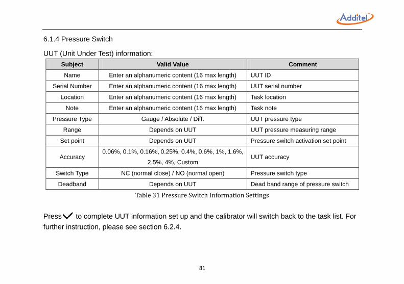
81
6.1.4 Pressure Switch
UUT (Unit Under Test) information:
Subject Valid Value Comment
Name Enter an alphanumeric content (16 max length) UUT ID
Serial Number Enter an alphanumeric content (16 max length) UUT serial number
Location Enter an alphanumeric content (16 max length) Task location
Note Enter an alphanumeric content (16 max length) Task note
Pressure Type Gauge / Absolute / Diff. UUT pressure type
Range Depends on UUT UUT pressure measuring range
Set point Depends on UUT Pressure switch activation set point
Accuracy 0.06%, 0.1%, 0.16%, 0.25%, 0.4%, 0.6%, 1%, 1.6%,
2.5%, 4%, Custom UUT accuracy
Switch Type NC (normal close) / NO (normal open) Pressure switch type
Deadband Depends on UUT Dead band range of pressure switch
Table 31 Pressure Switch Information Settings
Press to complete UUT information set up and the calibrator will switch back to the task list. For
further instruction, please see section 6.2.4.
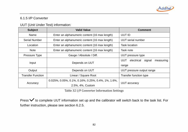
82
6.1.5 I/P Converter
UUT (Unit Under Test) information:
Subject Valid Value Comment
Name Enter an alphanumeric content (16 max length) UUT ID
Serial Number Enter an alphanumeric content (16 max length) UUT serial number
Location Enter an alphanumeric content (16 max length) Task location
Note Enter an alphanumeric content (16 max length) Task note
Pressure Type Gauge / Absolute / Diff. UUT pressure type
Input Depends on UUT UUT electrical signal measuring
range
Output Depends on UUT UUT pressure output range
Transfer Function Linear / Square Root Transfer function type
Accuracy 0.025%, 0.05%, 0.1%, 0.16%, 0.25%, 0.4%, 1%, 1.6%,
2.5%, 4%, Custom UUT accuracy
Table 32 I/P Converter Information Settings
Press to complete UUT information set up and the calibrator will switch back to the task list. For
further instruction, please see section 6.2.5.
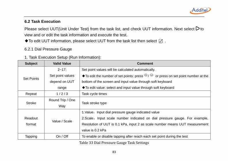
83
6.2 Task Execution
Please select UUT(Unit Under Test) from the task list, and check UUT information. Next select to
view and or edit the task information and execute the test.
◆To edit UUT information, please select UUT from the task list then select .
6.2.1 Dial Pressure Gauge
1. Task Execution Setup (Run Information):
Subject Valid Value Comment
Set Points
2~17;
Set point values
depend on UUT
range
Set point values will be calculated automatically.
◆To edit the number of set points: press / or press on set point number at the
bottom of the screen and input value through soft keyboard
◆To edit value: select and input value through soft keyboard
Repeat 1 / 2 / 3 Task cycle times
Stroke Round Trip / One
Way Task stroke type
Readout
format Value / Scale
1.Value:Input dial pressure gauge indicated value
2.Scale:Input scale number indicated on dial pressure gauge. For example,
Resolution of UUT is 0.1 kPa, input 2 as scale number means UUT measurement
value is 0.2 kPa
Tapping On / Off To enable or disable tapping after reach each set point during the test
Table 33 Dial Pressure Gauge Task Settings
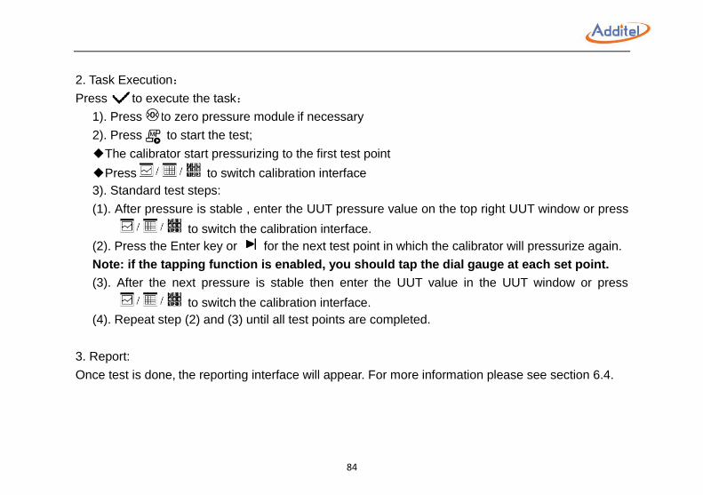
84
2. Task Execution:
Press to execute the task:
1). Press to zero pressure module if necessary
2). Press to start the test;
◆The calibrator start pressurizing to the first test point
◆Press to switch calibration interface
3). Standard test steps:
(1). After pressure is stable , enter the UUT pressure value on the top right UUT window or press
to switch the calibration interface.
(2). Press the Enter key or for the next test point in which the calibrator will pressurize again.
Note: if the tapping function is enabled, you should tap the dial gauge at each set point.
(3). After the next pressure is stable then enter the UUT value in the UUT window or press
to switch the calibration interface.
(4). Repeat step (2) and (3) until all test points are completed.
3. Report:
Once test is done, the reporting interface will appear. For more information please see section 6.4.
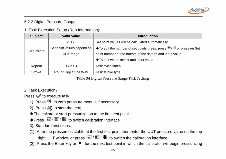
85
6.2.2 Digital Pressure Gauge
1. Task Execution Setup (Run Information):
Subject Valid Value Introduction
Set Points
2~17;
Set point values depend on
UUT range
Set point values will be calculated automatically.
◆To edit the number of set points press: press / or press on Set
point number at the bottom of the screen and input value
◆To edit value: select and input value
Repeat 1 / 2 / 3 Task cycle times
Stroke Round Trip / One Way Task stroke type
Table 34 Digital Pressure Gauge Task Settings
2. Task Execution:
Press to execute task:
1). Press to zero pressure module if necessary.
2). Press to start the test;
◆The calibrator start pressurization to the first test point
◆Press to switch calibration interface
3). Standard test steps:
(1). After the pressure is stable at the first test point then enter the UUT pressure value on the top
right UUT window or press to switch the calibration interface.
(2). Press the Enter key or for the next test point in which the calibrator will begin pressurizing
86
again.
(3). After the pressure is stable enter the UUT value.
(4). Repeat step 2 and 3 until all test points are completed.
3. Report:
Once a test is complete, the test report interface will appear. For more information please see section
6.4.
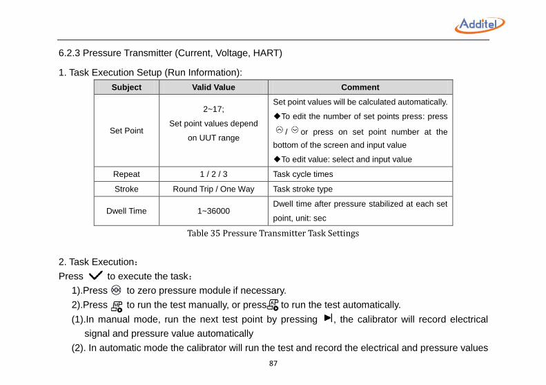
87
6.2.3 Pressure Transmitter (Current, Voltage, HART)
1. Task Execution Setup (Run Information):
Subject Valid Value Comment
Set Point
2~17;
Set point values depend
on UUT range
Set point values will be calculated automatically.
◆To edit the number of set points press: press
/ or press on set point number at the
bottom of the screen and input value
◆To edit value: select and input value
Repeat 1 / 2 / 3 Task cycle times
Stroke Round Trip / One Way Task stroke type
Dwell Time 1~36000 Dwell time after pressure stabilized at each set
point, unit: sec
Table 35 Pressure Transmitter Task Settings
2. Task Execution:
Press to execute the task:
1).Press to zero pressure module if necessary.
2).Press to run the test manually, or press to run the test automatically.
(1).In manual mode, run the next test point by pressing , the calibrator will record electrical
signal and pressure value automatically
(2). In automatic mode the calibrator will run the test and record the electrical and pressure values
88
automatically.
◆Press to switch calibration interface
3. Report:
Once a test is complete, the test report interface will appear. For more information please see section
6.4.
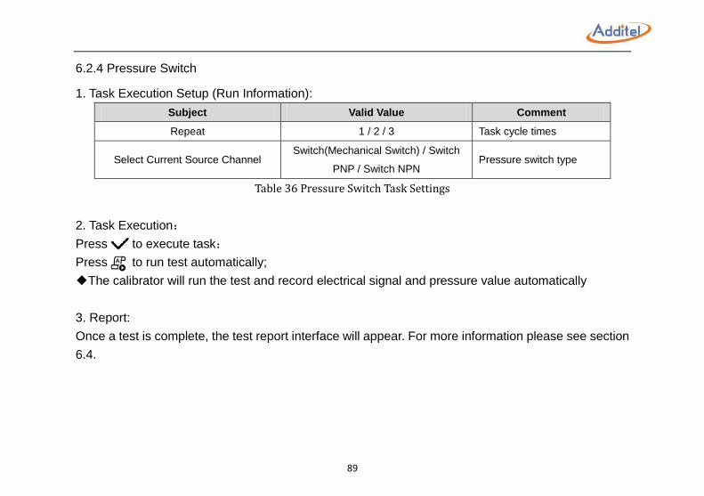
89
6.2.4 Pressure Switch
1. Task Execution Setup (Run Information):
Subject Valid Value Comment
Repeat 1 / 2 / 3 Task cycle times
Select Current Source Channel Switch(Mechanical Switch) / Switch
PNP / Switch NPN Pressure switch type
Table 36 Pressure Switch Task Settings
2. Task Execution:
Press to execute task:
Press to run test automatically;
◆The calibrator will run the test and record electrical signal and pressure value automatically
3. Report:
Once a test is complete, the test report interface will appear. For more information please see section
6.4.
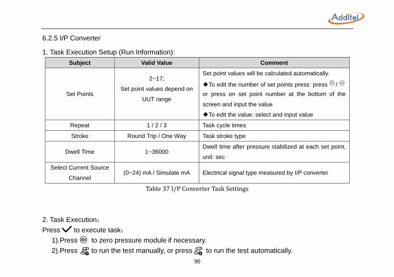
90
6.2.5 I/P Converter
1. Task Execution Setup (Run Information):
Subject Valid Value Comment
Set Points
2~17;
Set point values depend on
UUT range
Set point values will be calculated automatically.
◆To edit the number of set points press: press /
or press on set point number at the bottom of the
screen and input the value
◆To edit the value: select and input value
Repeat 1 / 2 / 3 Task cycle times
Stroke Round Trip / One Way Task stroke type
Dwell Time 1~36000 Dwell time after pressure stabilized at each set point,
unit: sec
Select Current Source
Channel (0~24) mA / Simulate mA Electrical signal type measured by I/P converter
Table 37 I/P Converter Task Settings
2. Task Execution:
Press to execute task:
1).Press to zero pressure module if necessary.
2).Press to run the test manually, or press to run the test automatically.
91
(1).In manual mode, run the next test point by pressing , the calibrator will record electrical
signal and pressure value automatically.
(2).In automatic mode, the calibrator will run the test and record electrical signal and pressure
value automatically.
◆Press to switch calibration interface
3. Report:
Once a test is complete, the test report interface will appear. For more information please see section
6.4.
6.3 Task Delete
To delete a task: In task list, press and select Clear All Tasks or Task delete management.
◆In task delete management interface, select to select all tasks or select single or multiple tasks,
then press to delete selected tasks.
92
6.4 End of Task
Once a test is complete, the test report interface appears.
◆Report interface can be displayed in a chart or data format by pressing
◆The test data can be canceled and the test will restart by pressing
◆To save the report press and enter the information below:
Save Options:
Subject Valid Value Comment
Operator Alphanumeric content (16 max length) Test operator ID
Execute Date 2000/01/01~2099/12/31 Execution date
Temperature -20~100 Environment temperature during test , unit: ℃
Humidity 0~100 Environment humidity during test
Table 38 Task Save Operation
◆ The report can be saved as As Found, As Left or Both (As Found and As Left)
93
7. Data Logger (Only available on 760-X-DL) To use data logger function, please select Data Logger under Main Menu .
1. The data logging functions available are listed below:
①Electrical Signal: Current / voltage measurement, pressure switch (mechanical, PNP, NPN)
measurement, current output (0~24 mA, simulate mA), and HART device electrical signal are
available for data logging.
②Pressure Measurement: Internal pressure module and external pressure module.
◆Data logging is available when the external pressure module is properly connected
◆At most, 4 channels can be logged independently or together: One electrical signal channel, one
pressure measurement channel and two external pressure module channels;
2. Data Logger Channel Setup:
Press or to add or delete channels.
◆By selecting a channel from the channel list, you can view the channel number, change the logging
content and change the units
◆Channel numbers will be rearranged once a channel has been deleted
3. Data logger setup:
Press the data logger details area which is on the bottom of the screen to change data logger setup:
94
Subject Valid Value Comment
Trigger Periodic Data logger activate type, read only
Interval 0.1~999999 Data logging internal, unit: sec
Samples 1-999999 Data logging sample number
Time 0:00:00~999:59:59 Data logging total time span
Table 39 Data Logger Setup
NOTE:Interval x Samples = Times
4. To start data logging, press :
1). Input data logging name, notes, and operator information, then select .
2). The calibrator will start data logging automatically.
◆When the data logging process has started, data begins to record automatically
◆Press to see data logging chart
◆When in the chart view the different channels are represented by a different color:
Theme Channel 1 Channel 2 Channel 3 Channel 4
White Blue Orange Aqua Green
Black Blue Orange Deep Pink Green
Table 40 Data Logger Chart
◆To stop logging press
◆Press to enter Logger Results interface for data review
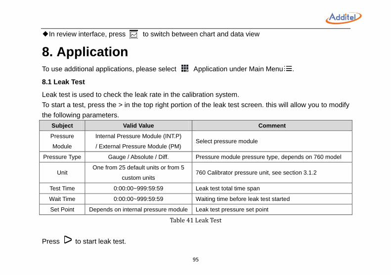
95
◆In review interface, press to switch between chart and data view
8. Application To use additional applications, please select Application under Main Menu .
8.1 Leak Test
Leak test is used to check the leak rate in the calibration system.
To start a test, press the > in the top right portion of the leak test screen. this will allow you to modify
the following parameters.
Subject Valid Value Comment
Pressure
Module
Internal Pressure Module (INT.P)
/ External Pressure Module (PM) Select pressure module
Pressure Type Gauge / Absolute / Diff. Pressure module pressure type, depends on 760 model
Unit One from 25 default units or from 5
custom units 760 Calibrator pressure unit, see section 3.1.2
Test Time 0:00:00~999:59:59 Leak test total time span
Wait Time 0:00:00~999:59:59 Waiting time before leak test started
Set Point Depends on internal pressure module Leak test pressure set point
Table 41 Leak Test
Press to start leak test.
96
8.2 Pressure Unit Converter
Each Additel 760 calibrator has a built-in pressure unit converter.
◆Press on any unit and input the value you would like to convert to

97
9. Service
9.1 Inlet Port Filter
Figure 18 Inlet Port Filter
To change inlet port filter:
1). Remove battery and screw 1 and 2 by using Allen Key (2.5mm)
2). Remove back cover
3). Change the filter
Maintenance Cycle: 3 ~ 6 months depending on use.
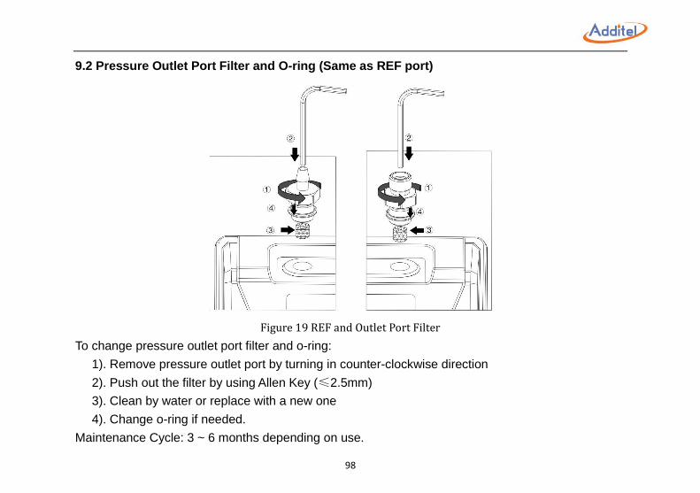
98
9.2 Pressure Outlet Port Filter and O-ring (Same as REF port)
Figure 19 REF and Outlet Port Filter
To change pressure outlet port filter and o-ring:
1). Remove pressure outlet port by turning in counter-clockwise direction
2). Push out the filter by using Allen Key (≤2.5mm)
3). Clean by water or replace with a new one
4). Change o-ring if needed.
Maintenance Cycle: 3 ~ 6 months depending on use.
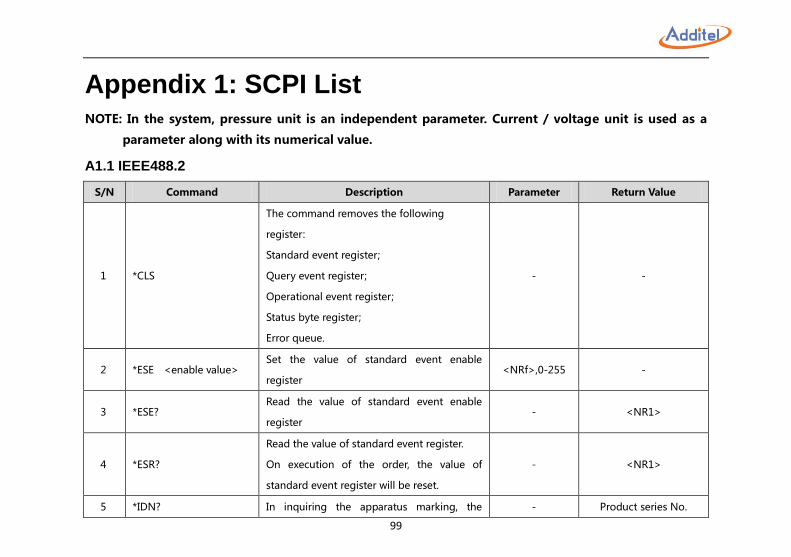
99
Appendix 1: SCPI List NOTE: In the system, pressure unit is an independent parameter. Current / voltage unit is used as a
parameter along with its numerical value.
A1.1 IEEE488.2
S/N Command Description Parameter Return Value
1 *CLS
The command removes the following
register:
Standard event register;
Query event register;
Operational event register;
Status byte register;
Error queue.
- -
2 *ESE <enable value> Set the value of standard event enable
register <NRf>,0-255 -
3 *ESE? Read the value of standard event enable
register - <NR1>
4 *ESR?
Read the value of standard event register.
On execution of the order, the value of
standard event register will be reset.
- <NR1>
5 *IDN? In inquiring the apparatus marking, the - Product series No.
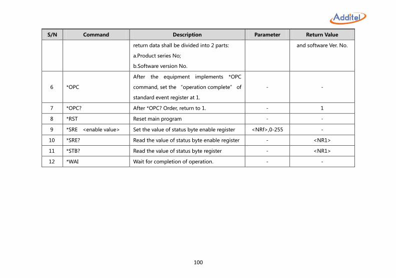
100
S/N Command Description Parameter Return Value
return data shall be divided into 2 parts:
a.Product series No;
b.Software version No.
and software Ver. No.
6 *OPC
After the equipment implements *OPC
command, set the “operation complete” of
standard event register at 1.
- -
7 *OPC? After *OPC? Order, return to 1. - 1
8 *RST Reset main program - -
9 *SRE <enable value> Set the value of status byte enable register <NRf>,0-255 -
10 *SRE? Read the value of status byte enable register - <NR1>
11 *STB? Read the value of status byte register - <NR1>
12 *WAI Wait for completion of operation. - -
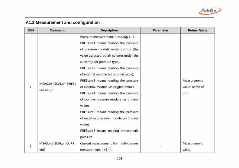
101
A1.2 Measurement and configuration
S/N Command Description Parameter Return Value
1 MEASure[:SCALar][:PRESs
ure<n>]?
Pressure measurement. n valuing 1~6.
PRESsure1 means reading the pressure
of pressure module under control (the
value adjusted by air column under the
currently set pressure type);
PRESsure2 means reading the pressure
of internal module (as original value);
PRESsure3 means reading the pressure
of external module (as original value);
PRESsure4 means reading the pressure
of positive pressure module (as original
value);
PRESsure5 means reading the pressure
of negative pressure module (as original
value);
PRESsure6 means reading atmospheric
pressure
-
Measurement
value: name of
unit
2 MEASure[:SCALar]:CURR
ent?
Current measurement. For multi-channel
measurement, n=1~4. -
Measurement
value
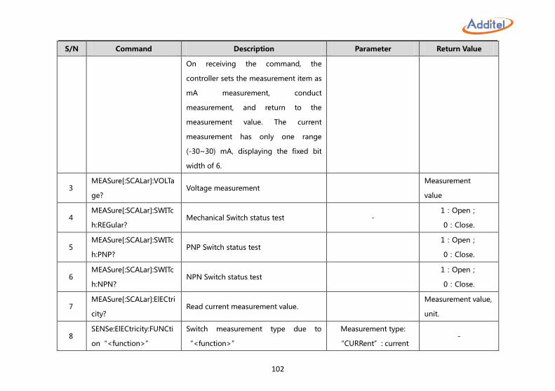
102
S/N Command Description Parameter Return Value
On receiving the command, the
controller sets the measurement item as
mA measurement, conduct
measurement, and return to the
measurement value. The current
measurement has only one range
(-30~30) mA, displaying the fixed bit
width of 6.
3 MEASure[:SCALar]:VOLTa
ge? Voltage measurement
Measurement
value
4 MEASure[:SCALar]:SWITc
h:REGular? Mechanical Switch status test -
1:Open;
0:Close.
5 MEASure[:SCALar]:SWITc
h:PNP? PNP Switch status test
1:Open;
0:Close.
6 MEASure[:SCALar]:SWITc
h:NPN? NPN Switch status test
1:Open;
0:Close.
7 MEASure[:SCALar]:ElECtri
city? Read current measurement value.
Measurement value,
unit.
8 SENSe:ElECtricity:FUNCti
on“<function>”
Switch measurement type due to
“<function>”
Measurement type:
“CURRent”: current -
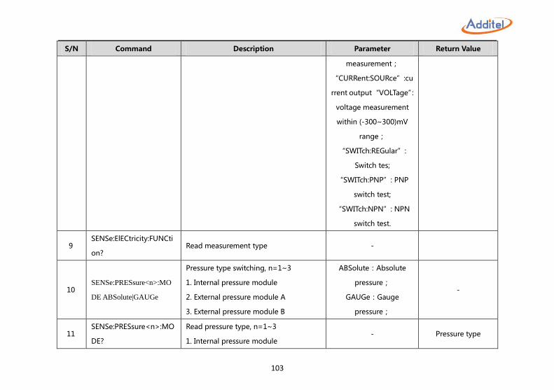
103
S/N Command Description Parameter Return Value
measurement;
“CURRent:SOURce”:cu
rrent output “VOLTage”:
voltage measurement
within (-300~300)mV
range;
“SWITch:REGular”:
Switch tes;
“SWITch:PNP”: PNP
switch test;
“SWITch:NPN”: NPN
switch test.
9 SENSe:ElECtricity:FUNCti
on? Read measurement type -
10 SENSe:PRESsure<n>:MO
DE ABSolute|GAUGe
Pressure type switching, n=1~3
1. Internal pressure module
2. External pressure module A
3. External pressure module B
ABSolute:Absolute
pressure;
GAUGe:Gauge
pressure;
-
11 SENSe:PRESsure<n>:MO
DE?
Read pressure type, n=1~3
1. Internal pressure module - Pressure type
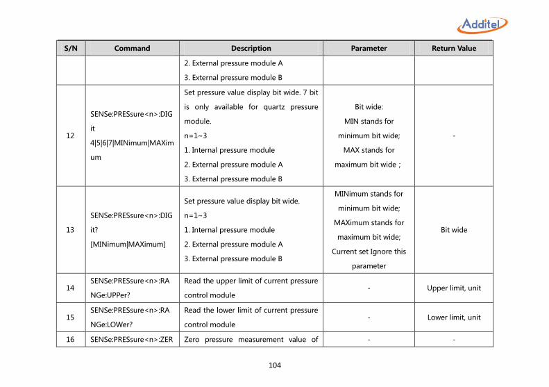
104
S/N Command Description Parameter Return Value
2. External pressure module A
3. External pressure module B
12
SENSe:PRESsure<n>:DIG
it
4|5|6|7|MINimum|MAXim
um
Set pressure value display bit wide. 7 bit
is only available for quartz pressure
module.
n=1~3
1. Internal pressure module
2. External pressure module A
3. External pressure module B
Bit wide:
MIN stands for
minimum bit wide;
MAX stands for
maximum bit wide;
-
13
SENSe:PRESsure<n>:DIG
it?
[MINimum|MAXimum]
Set pressure value display bit wide.
n=1~3
1. Internal pressure module
2. External pressure module A
3. External pressure module B
MINimum stands for
minimum bit wide;
MAXimum stands for
maximum bit wide;
Current set Ignore this
parameter
Bit wide
14 SENSe:PRESsure<n>:RA
NGe:UPPer?
Read the upper limit of current pressure
control module - Upper limit, unit
15 SENSe:PRESsure<n>:RA
NGe:LOWer?
Read the lower limit of current pressure
control module - Lower limit, unit
16 SENSe:PRESsure<n>:ZER Zero pressure measurement value of - -
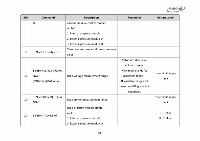
105
S/N Command Description Parameter Return Value
O current pressure control module.
n=1~3
1. Internal pressure module
2. External pressure module A
3. External pressure module B
17 SENSe:ElECtricity:ZERO Zero current electrical measurement
value - -
18
SENSe:VOLTage[:DC]:RA
NGe?
[MINimum|MAXimum]
Read voltage measurement range
MINimum stands for
minimum range;
MAXimum stands for
maximum range;
All available ranges will
be returned if ignore this
parameter.
Lower limit, upper
limit
19 SENSe:CURRent[:DC]:RA
NGe? Read current measurement range -
Lower limit, upper
limit
20 SENSe<n>:ONLine?
Read pressure module status.
n=1~3
1. Internal pressure module
2. External pressure module A
1:Online
0:Offline
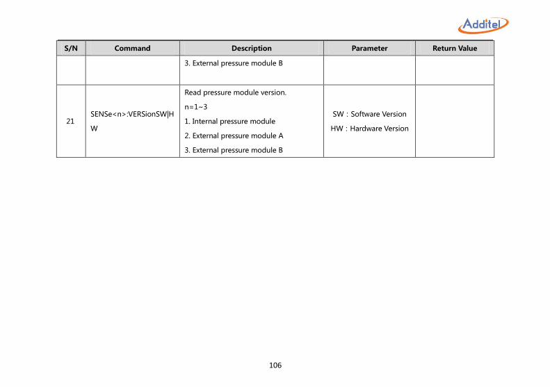
106
S/N Command Description Parameter Return Value
3. External pressure module B
21 SENSe<n>:VERSionSW|H
W
Read pressure module version.
n=1~3
1. Internal pressure module
2. External pressure module A
3. External pressure module B
SW:Software Version
HW:Hardware Version
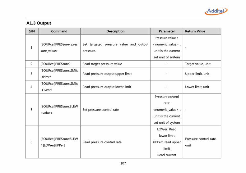
107
A1.3 Output
S/N Command Description Parameter Return Value
1 [SOURce:]PRESsure<pres
sure_value>
Set targeted pressure value and output
pressure.
Pressure value:
<numeric_value>,
unit is the current
set unit of system
-
2 [SOURce:]PRESsure? Read target pressure value - Target value, unit
3 [SOURce:]PRESsure:LIMit:
UPPer? Read pressure output upper limit - Upper limit, unit
4 [SOURce:]PRESsure:LIMit:
LOWer? Read pressure output lower limit - Lower limit, unit
5 [SOURce:]PRESsure:SLEW
<value> Set pressure control rate
Pressure control
rate:
<numeric_value>,
unit is the current
set unit of system
-
6 [SOURce:]PRESsure:SLEW
? [LOWer|UPPer] Read pressure control rate
LOWer: Read
lower limit
UPPer: Read upper
limit
Read current
Pressure control rate,
unit
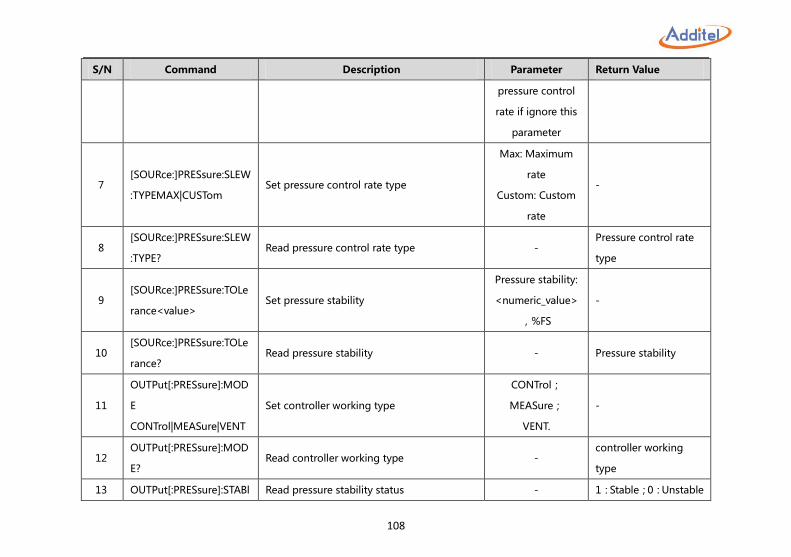
108
S/N Command Description Parameter Return Value
pressure control
rate if ignore this
parameter
7 [SOURce:]PRESsure:SLEW
:TYPEMAX|CUSTom Set pressure control rate type
Max: Maximum
rate
Custom: Custom
rate
-
8 [SOURce:]PRESsure:SLEW
:TYPE? Read pressure control rate type -
Pressure control rate
type
9 [SOURce:]PRESsure:TOLe
rance<value> Set pressure stability
Pressure stability:
<numeric_value>
,%FS
-
10 [SOURce:]PRESsure:TOLe
rance? Read pressure stability - Pressure stability
11
OUTPut[:PRESsure]:MOD
E
CONTrol|MEASure|VENT
Set controller working type
CONTrol;
MEASure;
VENT.
-
12 OUTPut[:PRESsure]:MOD
E? Read controller working type -
controller working
type
13 OUTPut[:PRESsure]:STABl Read pressure stability status - 1:Stable;0:Unstable
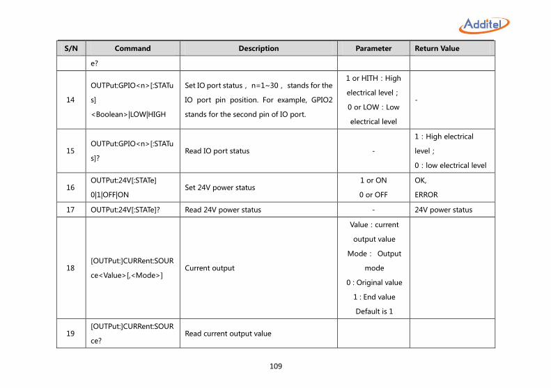
109
S/N Command Description Parameter Return Value
e?
14
OUTPut:GPIO<n>[:STATu
s]
<Boolean>|LOW|HIGH
Set IO port status, n=1~30, stands for the
IO port pin position. For example, GPIO2
stands for the second pin of IO port.
1 or HITH:High
electrical level;
0 or LOW:Low
electrical level
-
15 OUTPut:GPIO<n>[:STATu
s]? Read IO port status -
1:High electrical
level;
0:low electrical level
16 OUTPut:24V[:STATe]
0|1|OFF|ON Set 24V power status
1 or ON
0 or OFF
OK,
ERROR
17 OUTPut:24V[:STATe]? Read 24V power status - 24V power status
18 [OUTPut:]CURRent:SOUR
ce<Value>[,<Mode>] Current output
Value:current
output value
Mode: Output
mode
0 : Original value
1 : End value
Default is 1
19 [OUTPut:]CURRent:SOUR
ce? Read current output value
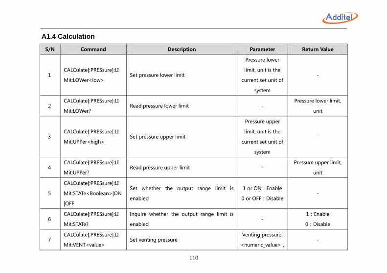
110
A1.4 Calculation
S/N Command Description Parameter Return Value
1 CALCulate[:PRESsure]:LI
Mit:LOWer<low> Set pressure lower limit
Pressure lower
limit, unit is the
current set unit of
system
-
2 CALCulate[:PRESsure]:LI
Mit:LOWer? Read pressure lower limit -
Pressure lower limit,
unit
3 CALCulate[:PRESsure]:LI
Mit:UPPer<high> Set pressure upper limit
Pressure upper
limit, unit is the
current set unit of
system
-
4 CALCulate[:PRESsure]:LI
Mit:UPPer? Read pressure upper limit -
Pressure upper limit,
unit
5
CALCulate[:PRESsure]:LI
Mit:STATe<Boolean>|ON
|OFF
Set whether the output range limit is
enabled
1 or ON:Enable
0 or OFF:Disable -
6 CALCulate[:PRESsure]:LI
Mit:STATe?
Inquire whether the output range limit is
enabled -
1:Enable
0:Disable
7 CALCulate[:PRESsure]:LI
Mit:VENT<value> Set venting pressure
Venting pressure:
<numeric_value>, -
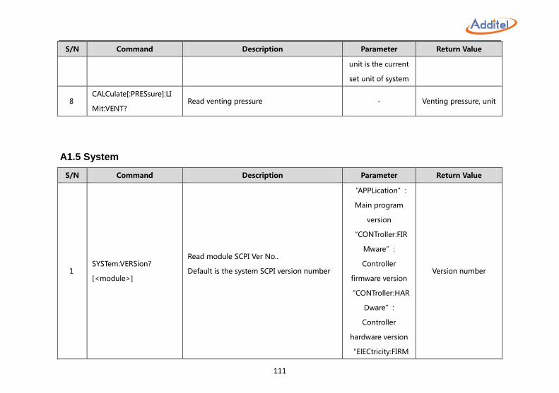
111
S/N Command Description Parameter Return Value
unit is the current
set unit of system
8 CALCulate[:PRESsure]:LI
Mit:VENT? Read venting pressure - Venting pressure, unit
A1.5 System
S/N Command Description Parameter Return Value
1 SYSTem:VERSion?
[<module>]
Read module SCPI Ver No..
Default is the system SCPI version number
“APPLication”:
Main program
version
“CONTroller:FIR
Mware”:
Controller
firmware version
“CONTroller:HAR
Dware”:
Controller
hardware version
“ElECtricity:FIRM
Version number
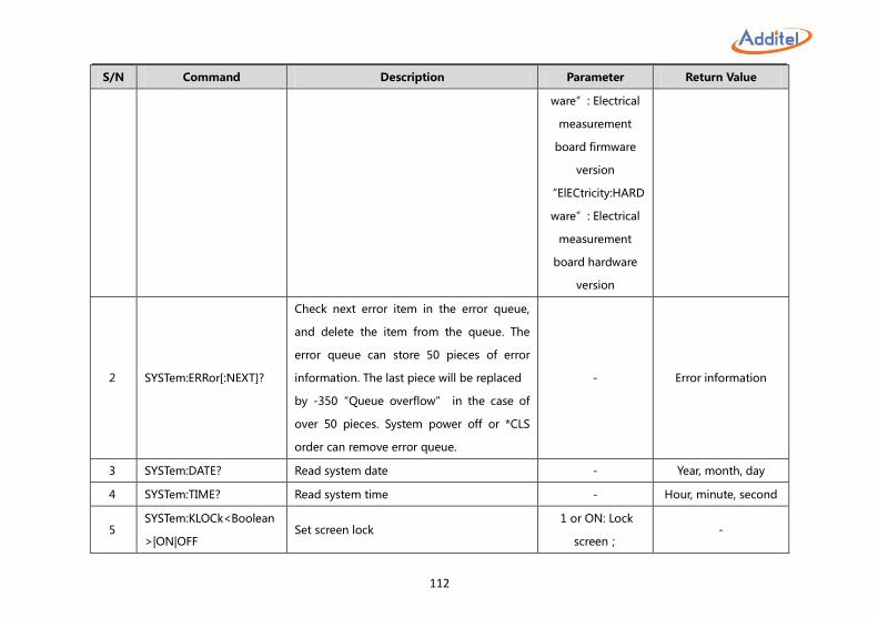
112
S/N Command Description Parameter Return Value
ware”: Electrical
measurement
board firmware
version
“ElECtricity:HARD
ware”: Electrical
measurement
board hardware
version
2 SYSTem:ERRor[:NEXT]?
Check next error item in the error queue,
and delete the item from the queue. The
error queue can store 50 pieces of error
information. The last piece will be replaced
by -350“Queue overflow” in the case of
over 50 pieces. System power off or *CLS
order can remove error queue.
- Error information
3 SYSTem:DATE? Read system date - Year, month, day
4 SYSTem:TIME? Read system time - Hour, minute, second
5 SYSTem:KLOCk<Boolean
>|ON|OFF Set screen lock
1 or ON: Lock
screen; -
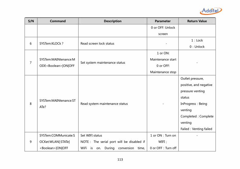
113
S/N Command Description Parameter Return Value
0 or OFF: Unlock
screen
6 SYSTem:KLOCk? Read screen lock status - 1:Lock
0:Unlock
7 SYSTem:MAINtenance:M
ODE<Boolean>|ON|OFF Set system maintenance status
1 or ON:
Maintenance start
0 or OFF:
Maintenance stop
-
8 SYSTem:MAINtenance:ST
ATe? Read system maintenance status -
Outlet pressure,
positive, and negative
pressure venting
status
InProgress:Being
venting
Completed:Complete
venting
Failed:Venting failed
9
SYSTem:COMMunicate:S
OCKet:WLAN[:STATe]
<Boolean>|ON|OFF
Set WIFI status
NOTE: The serial port will be disabled if
WiFi is on. During conversion time,
1 or ON:Turn on
WIFI;
0 or OFF:Turn off
-
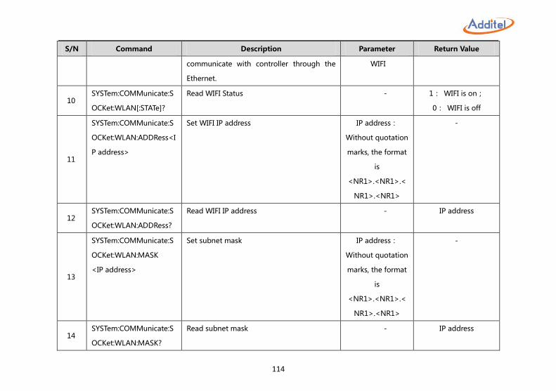
114
S/N Command Description Parameter Return Value
communicate with controller through the
Ethernet.
WIFI
10 SYSTem:COMMunicate:S
OCKet:WLAN[:STATe]?
Read WIFI Status - 1: WIFI is on;
0: WIFI is off
11
SYSTem:COMMunicate:S
OCKet:WLAN:ADDRess<I
P address>
Set WIFI IP address IP address:
Without quotation
marks, the format
is
<NR1>.<NR1>.<
NR1>.<NR1>
-
12 SYSTem:COMMunicate:S
OCKet:WLAN:ADDRess?
Read WIFI IP address - IP address
13
SYSTem:COMMunicate:S
OCKet:WLAN:MASK
<IP address>
Set subnet mask IP address:
Without quotation
marks, the format
is
<NR1>.<NR1>.<
NR1>.<NR1>
-
14 SYSTem:COMMunicate:S
OCKet:WLAN:MASK?
Read subnet mask - IP address
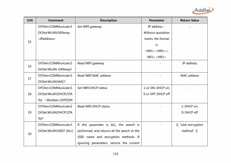
115
S/N Command Description Parameter Return Value
15
SYSTem:COMMunicate:S
OCKet:WLAN:GATeway
<IPaddress>
Set WIFI gateway IP address:
Without quotation
marks, the format
is
<NR1>.<NR1>.<
NR1>.<NR1>
-
16 SYSTem:COMMunicate:S
OCKet:WLAN: GATeway?
Read WIFI gateway - IP address
17 SYSTem:COMMunicate:S
OCKet:WLAN:MAC?
Read WIFI MAC address - MAC address
18
SYSTem:COMMunicate:S
OCKet:WLAN:DHCP[:STA
Te] <Boolean>|OFF|ON
Set WIFI DHCP status 1 or ON: DHCP on;
0 or OFF: DHCP off
-
19
SYSTem:COMMunicate:S
OCKet:WLAN:DHCP[:STA
Te]?
Read WIFI DHCP status - 1: DHCP on;
0: DHCP off
20
SYSTem:COMMunicate:S
OCKet:WLAN:SSID? [ALL]
If this parameter is ALL, the search is
performed, and returns all the search to the
SSID name and encryption methods. If
ignoring parameters, returns the current
- {[“ssid: encryption
method”]}
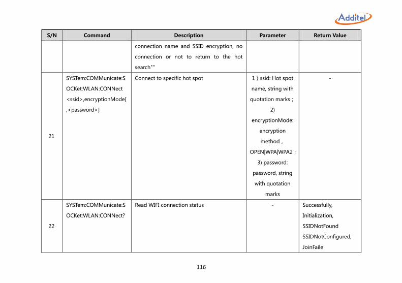
116
S/N Command Description Parameter Return Value
connection name and SSID encryption, no
connection or not to return to the hot
search""
21
SYSTem:COMMunicate:S
OCKet:WLAN:CONNect
<ssid>,encryptionMode[
,<password>]
Connect to specific hot spot 1)ssid: Hot spot
name, string with
quotation marks;
2)
encryptionMode:
encryption
method,
OPEN|WPA|WPA2;
3) password:
password, string
with quotation
marks
-
22
SYSTem:COMMunicate:S
OCKet:WLAN:CONNect?
Read WIFI connection status - Successfully,
Initialization,
SSIDNotFound
SSIDNotConfigured,
JoinFaile
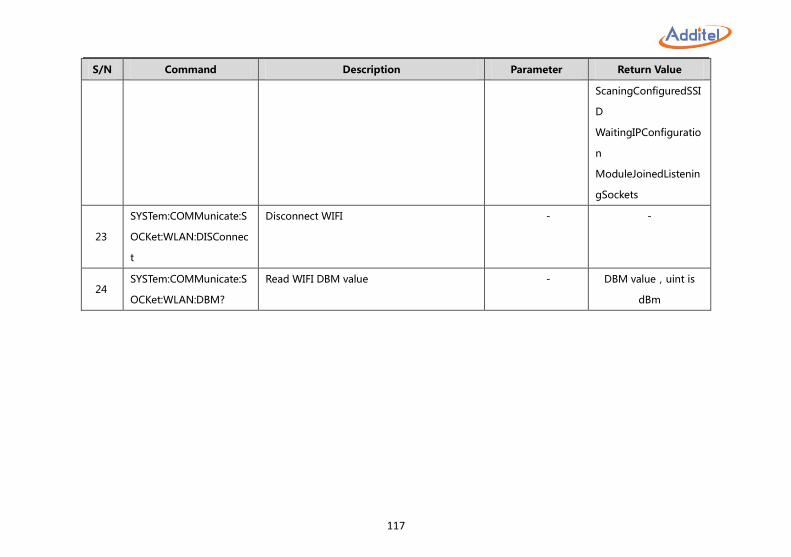
117
S/N Command Description Parameter Return Value
ScaningConfiguredSSI
D
WaitingIPConfiguratio
n
ModuleJoinedListenin
gSockets
23
SYSTem:COMMunicate:S
OCKet:WLAN:DISConnec
t
Disconnect WIFI - -
24 SYSTem:COMMunicate:S
OCKet:WLAN:DBM?
Read WIFI DBM value - DBM value,uint is
dBm
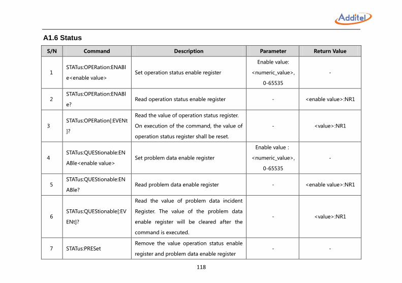
118
A1.6 Status
S/N Command Description Parameter Return Value
1 STATus:OPERation:ENABl
e<enable value> Set operation status enable register
Enable value:
<numeric_value>,
0-65535
-
2 STATus:OPERation:ENABl
e? Read operation status enable register - <enable value>:NR1
3 STATus:OPERation[:EVENt
]?
Read the value of operation status register.
On execution of the command, the value of
operation status register shall be reset.
- <value>:NR1
4 STATus:QUEStionable:EN
ABle<enable value> Set problem data enable register
Enable value:
<numeric_value>,
0-65535
-
5 STATus:QUEStionable:EN
ABle? Read problem data enable register - <enable value>:NR1
6 STATus:QUEStionable[:EV
ENt]?
Read the value of problem data incident
Register. The value of the problem data
enable register will be cleared after the
command is executed.
- <value>:NR1
7 STATus:PRESet Remove the value operation status enable
register and problem data enable register - -
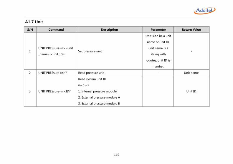
119
A1.7 Unit
S/N Command Description Parameter Return Value
1 UNIT:PRESsure<n><unit
_name>|<unit_ID> Set pressure unit
Unit:Can be a unit
name or unit ID,
unit name is a
string with
quotes, unit ID is
number.
-
2 UNIT:PRESsure<n>? Read pressure unit - Unit name
3 UNIT:PRESsure<n>:ID?
Read system unit ID
n= 1~3
1. Internal pressure module
2. External pressure module A
3. External pressure module B
Unit ID
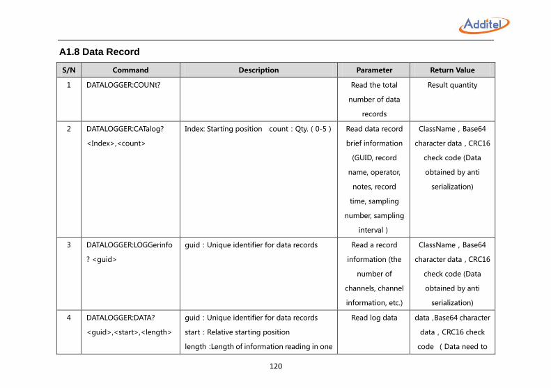
120
A1.8 Data Record
S/N Command Description Parameter Return Value
1 DATALOGGER:COUNt? Read the total
number of data
records
Result quantity
2 DATALOGGER:CATalog?
<Index>,<count>
Index: Starting position count:Qty.(0-5) Read data record
brief information
(GUID, record
name, operator,
notes, record
time, sampling
number, sampling
interval)
ClassName,Base64
character data,CRC16
check code (Data
obtained by anti
serialization)
3 DATALOGGER:LOGGerinfo
? <guid>
guid:Unique identifier for data records
Read a record
information (the
number of
channels, channel
information, etc.)
ClassName,Base64
character data,CRC16
check code (Data
obtained by anti
serialization)
4 DATALOGGER:DATA?
<guid>,<start>,<length>
guid:Unique identifier for data records
start:Relative starting position
length:Length of information reading in one
Read log data data,Base64 character
data,CRC16 check
code (Data need to
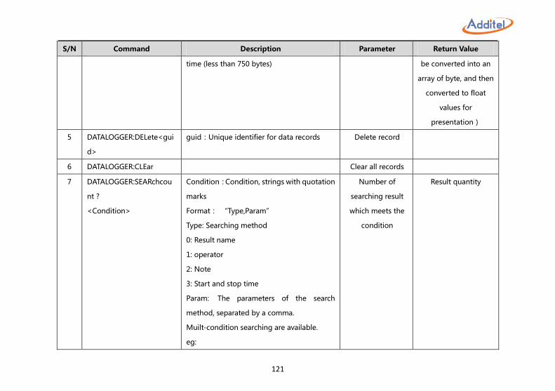
121
S/N Command Description Parameter Return Value
time (less than 750 bytes) be converted into an
array of byte, and then
converted to float
values for
presentation)
5 DATALOGGER:DELete<gui
d>
guid:Unique identifier for data records
Delete record
6 DATALOGGER:CLEar Clear all records
7 DATALOGGER:SEARchcou
nt ?
<Condition>
Condition:Condition, strings with quotation
marks
Format: “Type,Param”
Type: Searching method
0: Result name
1: operator
2: Note
3: Start and stop time
Param: The parameters of the search
method, separated by a comma.
Muilt-condition searching are available.
eg:
Number of
searching result
which meets the
condition
Result quantity
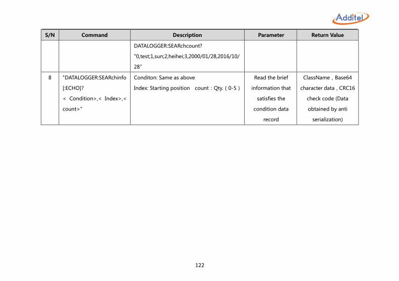
122
S/N Command Description Parameter Return Value
DATALOGGER:SEARchcount?
"0,test;1,sun;2,heihei;3,2000/01/28,2016/10/
28”
8 "DATALOGGER:SEARchinfo
[:ECHO]?
< Condition>,< Index>,<
count>"
Conditon: Same as above
Index: Starting position count:Qty.(0-5)
Read the brief
information that
satisfies the
condition data
record
ClassName,Base64
character data,CRC16
check code (Data
obtained by anti
serialization)
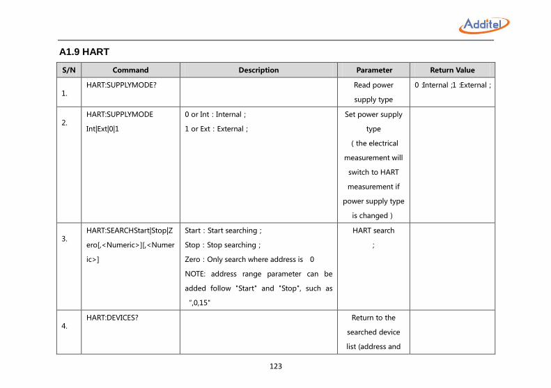
123
A1.9 HART
S/N Command Description Parameter Return Value
1. HART:SUPPLYMODE? Read power
supply type
0:Internal;1:External;
2. HART:SUPPLYMODE
Int|Ext|0|1
0 or Int:Internal;
1 or Ext:External;
Set power supply
type
(the electrical
measurement will
switch to HART
measurement if
power supply type
is changed)
3. HART:SEARCHStart|Stop|Z
ero[,<Numeric>][,<Numer
ic>]
Start:Start searching;
Stop:Stop searching;
Zero:Only search where address is 0
NOTE: address range parameter can be
added follow "Start" and "Stop", such as
“,0,15"
HART search
;
4. HART:DEVICES? Return to the
searched device
list (address and
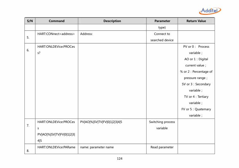
124
S/N Command Description Parameter Return Value
type)
5. HART:CONnect<address> Address: Connect to
searched device
6. HART:ONLDEVice:PROCes
s?
PV or 0: Process
variable;
AO or 1:Digital
current value;
% or 2:Percentage of
pressure range;
SV or 3:Secondary
variable;
TV or 4:Tertiary
variable;
FV or 5:Quatemary
variable;
7. HART:ONLDEVice:PROCes
s
PV|AO|%|SV|TV|FV|0|1|2|3|
4|5
PV|AO|%|SV|TV|FV|0|1|2|3|4|5 Switching process
variable
8. HART:ONLDEVice:PARame name: parameter name Read parameter
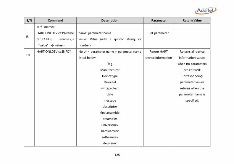
125
S/N Command Description Parameter Return Value
ter? <name>
9. HART:ONLDEVice:PARame
ter[:ECHO] <name>,<
“value”>|<value>
name: parameter name
value: Value (with a quoted string, or
number)
Set parameter
10. HART:ONLDEVice:INFO? No or < parameter name > parameter name
listed below:
Tag
Manufacturer
Devicetype
Deviceid
writeprotect
date
message
descriptor
finalassemble
preambles
universalrev
hardwarerev
softwarerev
devicerev
Return HART
device information
Returns all device
information values
when no parameters
are entered;
Corresponding
parameter values
returns when the
parameter name is
specified;
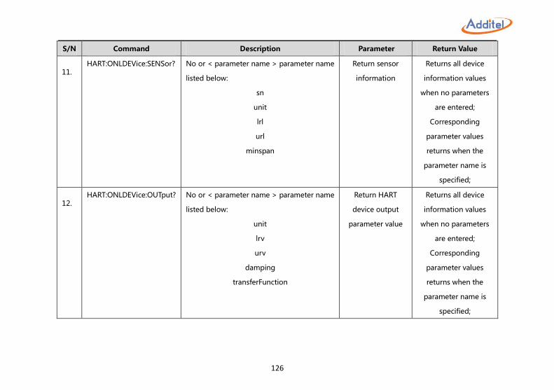
126
S/N Command Description Parameter Return Value
11. HART:ONLDEVice:SENSor? No or < parameter name > parameter name
listed below:
sn
unit
lrl
url
minspan
Return sensor
information
Returns all device
information values
when no parameters
are entered;
Corresponding
parameter values
returns when the
parameter name is
specified;
12. HART:ONLDEVice:OUTput? No or < parameter name > parameter name
listed below:
unit
lrv
urv
damping
transferFunction
Return HART
device output
parameter value
Returns all device
information values
when no parameters
are entered;
Corresponding
parameter values
returns when the
parameter name is
specified;
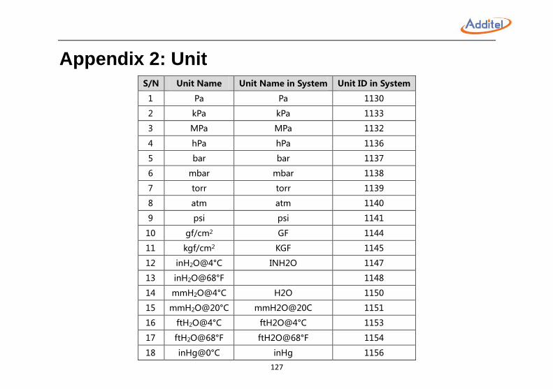
127
Appendix 2: Unit S/N Unit Name Unit Name in System Unit ID in System
1 Pa Pa 1130
2 kPa kPa 1133
3 MPa MPa 1132
4 hPa hPa 1136
5 bar bar 1137
6 mbar mbar 1138
7 torr torr 1139
8 atm atm 1140
9 psi psi 1141
10 gf/cm2 GF 1144
11 kgf/cm2 KGF 1145
12 inH2O@4°C INH2O 1147
13 inH2O@68°F 1148
14 mmH2O@4°C H2O 1150
15 mmH2O@20°C mmH2O@20C 1151
16 ftH2O@4°C ftH2O@4°C 1153
17 ftH2O@68°F ftH2O@68°F 1154
18 inHg@0°C inHg 1156
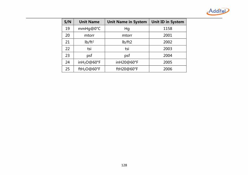
128
S/N Unit Name Unit Name in System Unit ID in System
19 mmHg@0°C Hg 1158
20 mtorr mtorr 2001
21 lb/ft2 lb/ft2 2002
22 tsi tsi 2003
23 psf psf 2004
24 inH2O@60°F inH20@60°F 2005
25 ftH2O@60°F ftH20@60°F 2006
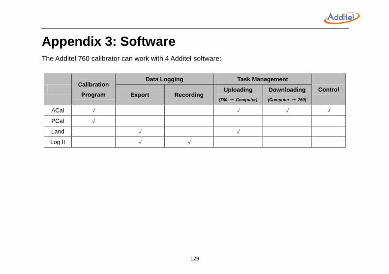
129
Appendix 3: Software The Additel 760 calibrator can work with 4 Additel software:
Calibration
Program
Data Logging Task Management
Control Export Recording
Uploading
(760 → Computer)
Downloading
(Computer → 760)
ACal √ √ √ √
PCal √
Land √ √
Log II √ √
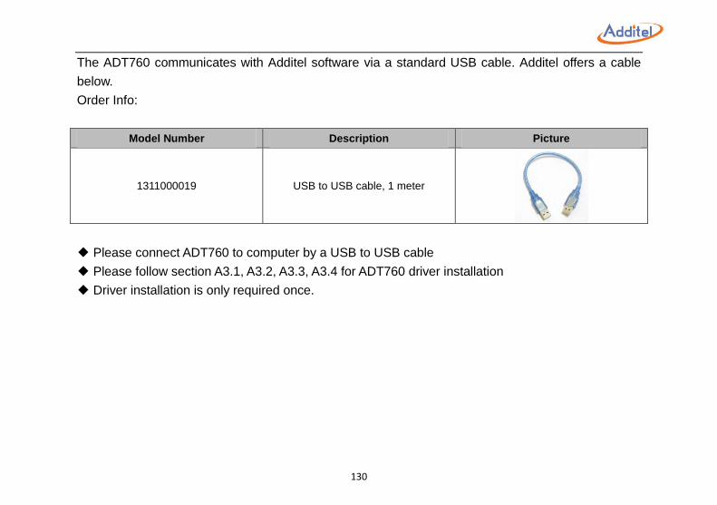
130
The ADT760 communicates with Additel software via a standard USB cable. Additel offers a cable
below.
Order Info:
Model Number Description Picture
1311000019 USB to USB cable, 1 meter
◆ Please connect ADT760 to computer by a USB to USB cable
◆ Please follow section A3.1, A3.2, A3.3, A3.4 for ADT760 driver installation
◆ Driver installation is only required once.
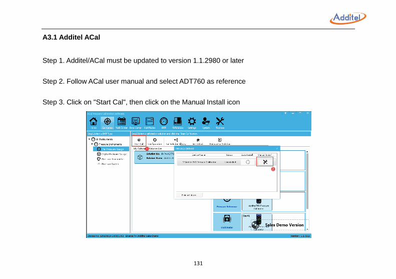
131
A3.1 Additel ACal
Step 1. Additel/ACal must be updated to version 1.1.2980 or later
Step 2. Follow ACal user manual and select ADT760 as reference
Step 3. Click on "Start Cal", then click on the Manual Install icon
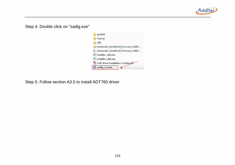
132
Step 4. Double click on "zadig.exe"
Step 5. Follow section A3.5 to install ADT760 driver
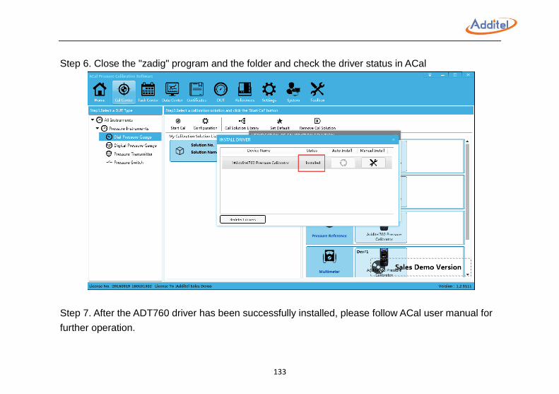
133
Step 6. Close the "zadig" program and the folder and check the driver status in ACal
Step 7. After the ADT760 driver has been successfully installed, please follow ACal user manual for
further operation.
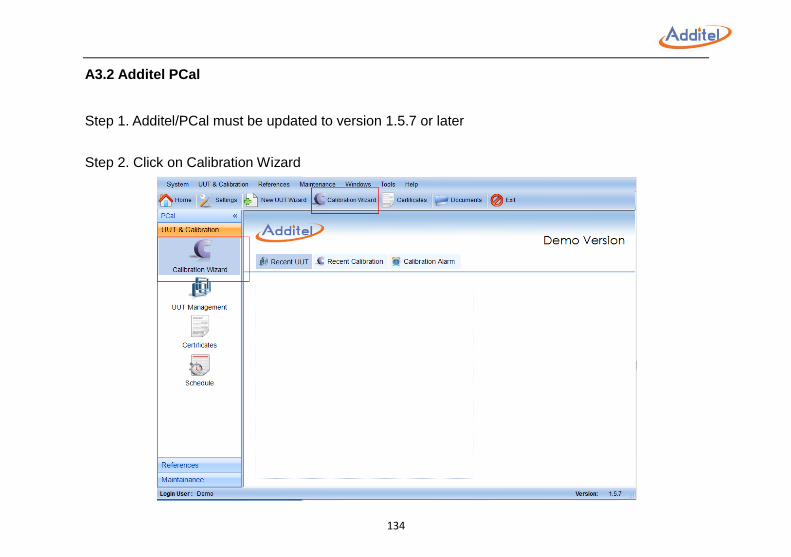
134
A3.2 Additel PCal
Step 1. Additel/PCal must be updated to version 1.5.7 or later
Step 2. Click on Calibration Wizard
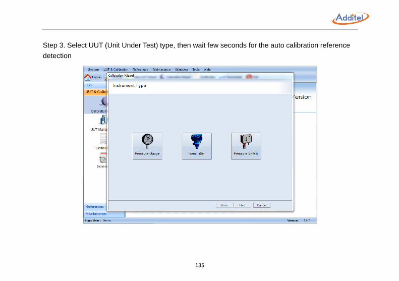
135
Step 3. Select UUT (Unit Under Test) type, then wait few seconds for the auto calibration reference
detection
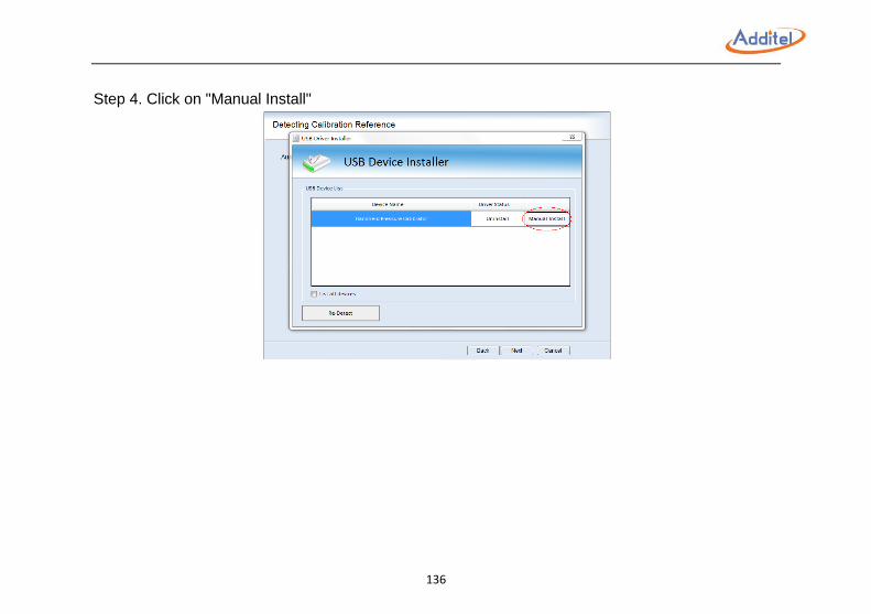
136
Step 4. Click on "Manual Install"
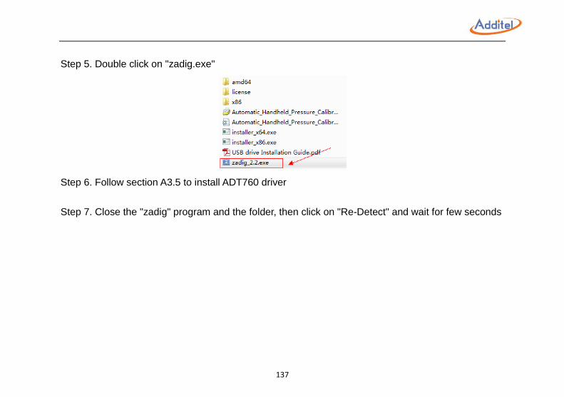
137
Step 5. Double click on "zadig.exe"
Step 6. Follow section A3.5 to install ADT760 driver
Step 7. Close the "zadig" program and the folder, then click on "Re-Detect" and wait for few seconds
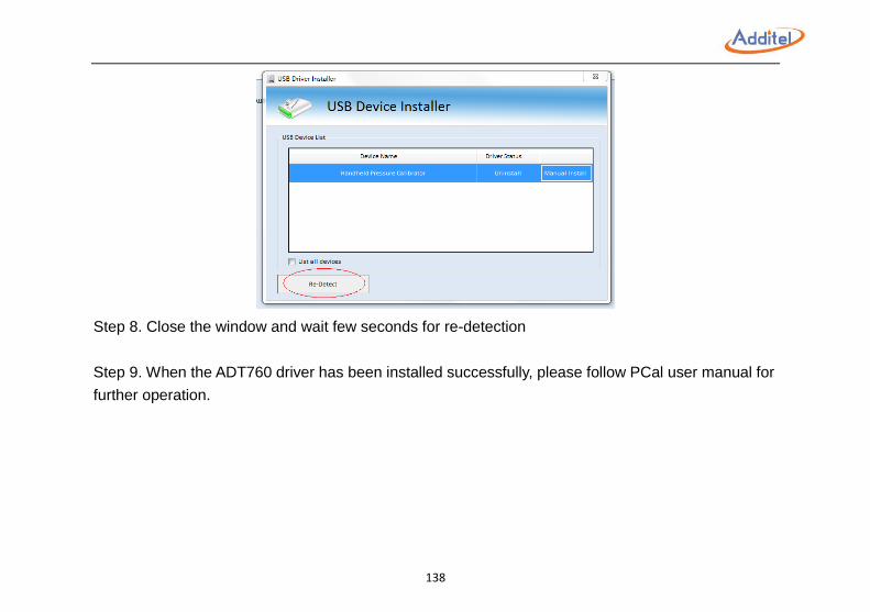
138
Step 8. Close the window and wait few seconds for re-detection
Step 9. When the ADT760 driver has been installed successfully, please follow PCal user manual for
further operation.
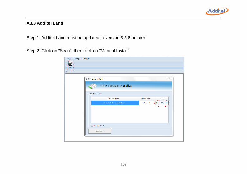
139
A3.3 Additel Land
Step 1. Additel Land must be updated to version 3.5.8 or later
Step 2. Click on "Scan", then click on "Manual Install"

140
Step 3. Double click on "zadig.exe"
Step 4. Follow section A3.5 to install the ADT760 driver
Step 5. Close the "zadig" program and the folder, then click on "Re-Detect" and wait for few seconds
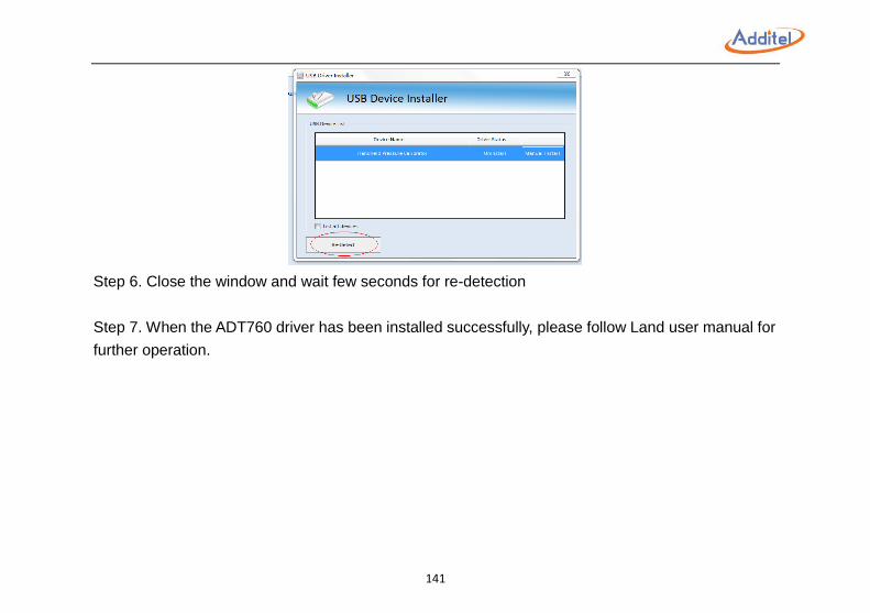
141
Step 6. Close the window and wait few seconds for re-detection
Step 7. When the ADT760 driver has been installed successfully, please follow Land user manual for
further operation.
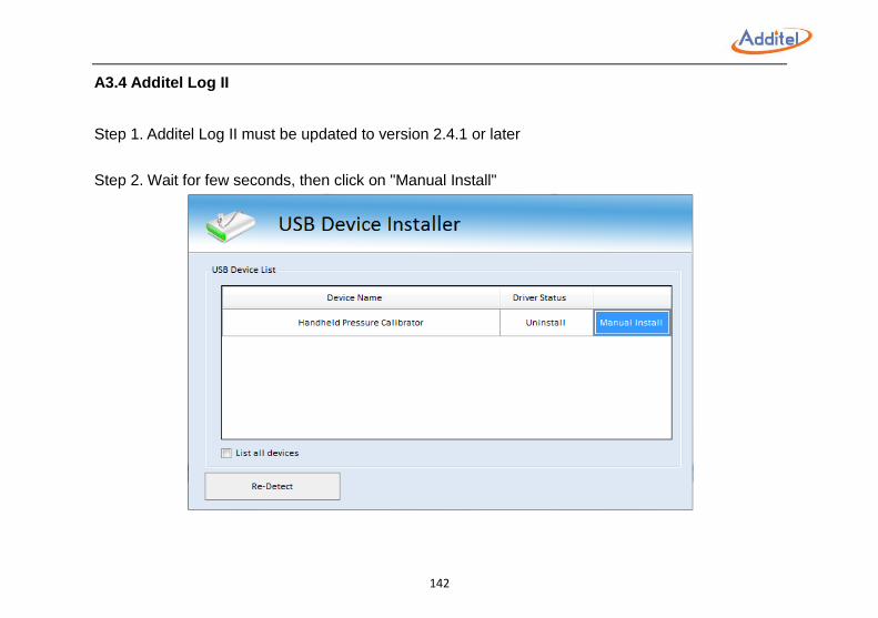
142
A3.4 Additel Log II
Step 1. Additel Log II must be updated to version 2.4.1 or later
Step 2. Wait for few seconds, then click on "Manual Install"
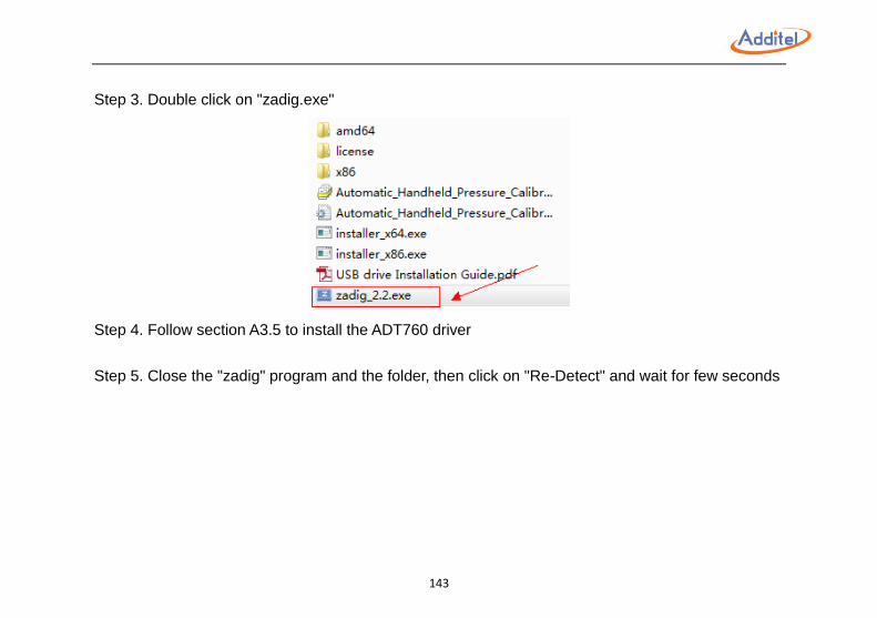
143
Step 3. Double click on "zadig.exe"
Step 4. Follow section A3.5 to install the ADT760 driver
Step 5. Close the "zadig" program and the folder, then click on "Re-Detect" and wait for few seconds
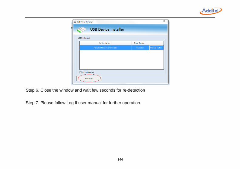
144
Step 6. Close the window and wait few seconds for re-detection
Step 7. Please follow Log II user manual for further operation.
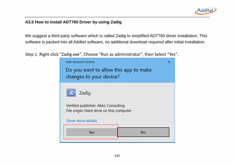
145
A3.5 How to install ADT760 Driver by using Zadig
We suggest a third party software which is called Zadig to simplified ADT760 driver installation. This
software is packed into all Additel software, no additional download required after initial installation.
Step 1. Right click "Zadig.exe", Choose “Run as administrator”, then Select “Yes”.
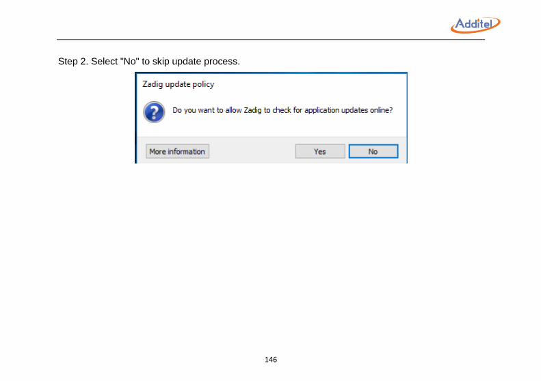
146
Step 2. Select "No" to skip update process.
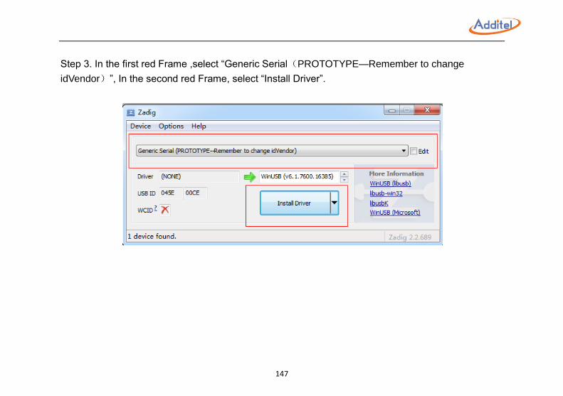
147
Step 3. In the first red Frame ,select “Generic Serial(PROTOTYPE—Remember to change
idVendor)”, In the second red Frame, select “Install Driver”.
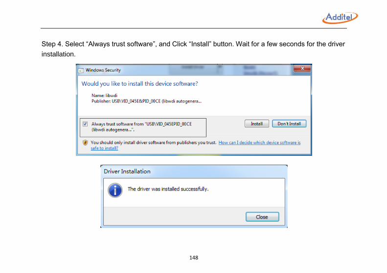
148
Step 4. Select “Always trust software”, and Click “Install” button. Wait for a few seconds for the driver
installation.
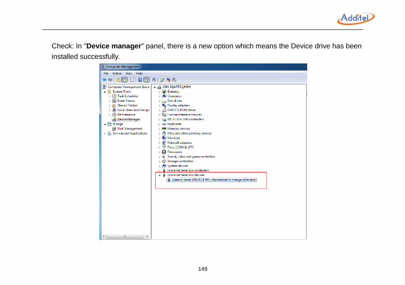
149
Check: In "Device manager" panel, there is a new option which means the Device drive has been
installed successfully.