ii.11_2012_01_25_trxlpe_urd_csa.pdf
TRANSCRIPT

Description
Single conductor cable with aluminum or copper conductors,triple extruded insulation system consisting of a thermosettingsemiconducting conductor shield, high dielectric strengthVOLTALENE® TRXLPE insulation, thermosetting semiconductinginsulation shield, copper concentric neutral wires, blackencapsulating linear low-density polyethylene (LLDPE) jacket.
Specifications Ratings
CSA C68.5 -40°C
For 90°C continuous, 130°C emergency, 250°C short-circuit operation.
Design Parameters
Conductor• Solid Class B compact or compressed concentric strand
aluminum alloy 1350 or soft drawn annealed copper per ASTM.
Conductor Shield• Extruded thermosetting semiconducting shield which is free
stripping from the conductor and bonded to the insulation.
Insulation• Natural high dielectric strength VOLTALENE® TRXLPE insulation,
exhibiting an optimum balance of mechanical and electricalproperties, insuring resistance to treeing.
Insulation Shield• Extruded thermosetting semiconducting shield with controlled
adhesion to the insulation providing the required balancebetween electrical integrity and ease of stripping.
Metallic Shield•Solid bare copper wires, helically applied and uniformly spaced.
Jacket• Black insulation sunlight resistant linear low-density
polyethylene encapsulating the neutral wires with threeextruded red stripes.
Options
• Black LLDPE jacket with no stripes
• Black PVC jacket sleeved over separator tape
• No jacket
• EPROTENAX™ (EPR) insulation
• Multiplex cables
• Tinned round or flat strap neutrals
• Strandseal®
• Super smooth conductor shield
• Cables made to AEIC CS8 and/or ICEA S-94-649
• 46kV
Installations
Conduit in Air Direct Buried
Underground Duct Isolated in Air
Wet Locations Dry Locations
With Messenger Utility Primary
CSA
5-46kV TRXLPE URD CSA
MEDIUM VOLTAGE UTILITY
section ii.11 1
2012.01.25
Prysmian Power Cables and Systems www.prysmianusa.com
www.prysmiancanada.com
United States: 700 Industrial Drive • Lexington, South Carolina 29072Canada: 137 Commerce Drive • R. R #3 • Prescott, Ontario K0E1T01-800-845-8507 (US) • 1-800-263-4405 (West-CAN) • 1-800-361-1418 (East-CAN)

TRXLPE URD CSA
Single Phase Operation (Full Neutral Design)
In Duct: One single cable in plastic duct, direct-buried, 90°C conductor temperature, 20°C ambient temperature, earth RHO of 90°C-cm/Watt, 100% load factor, 36 inch depthof burial, and shields short-circuited.
Direct Buried: One single cable, direct-buried, 90°C conductor temperature, 20°C ambienttemperature, earth RHO of 90°C-cm/Watt, 100% load factor, 36 inch depth of burial, andshields short-circuited.
Three Phase Operation (1/3 Neutral Design)
In Duct: Three single cables in plastic duct, direct-buried in a triangular configuration,90°C conductor temperature, 20°C ambient temperature, earth RHO of 90°C-cm/Watt,100% load factor, 36 inch depth of burial, and shields short-circuited.
Direct Buried: Three single cables, direct-buried, spaced 7.5 inches horizontally, 90°C conductor temperature, 20°C ambient temperature, earth RHO of 90°C-cm/Watt,100% load factor, 36 inch depth of burial, and shields short-circuited.
PRODUCT NOTES:
Items are Prysmian authorized stock.The above dimensions are approximate and subjectto normal manufacturing tolerances.Single Phase Impedance Values Assume Full Return in the Metallic Shield.All metric (SI) dimensions are derived from a softconversion.
†Ampacities are based on the following: Information Subject to Change without Notice.
MEDIUM VOLTAGE UTILITY
section ii.11 2
(A) (B) (C) (D) 90°C In Duct 90°C Direct Buried
Q4L01ZC 2 SOLID AL 90 10-#14 6.55 12.40 14.27 20.38 536 178 119 2.17 0.08 2.17 0.08 169 2.17 0.08 2.17 0.08Q4MØ1ZC 2 AWG AL 90 10-#14 6.81 12.55 14.43 20.53 542 178 120 2.20 0.08 2.20 0.08 170 2.20 0.08 2.20 0.08Q4NØ1ZC 1 SOLID AL 90 13-#14 7.34 13.18 15.06 21.16 629 178 136 1.70 0.08 1.70 0.08 193 1.70 0.08 1.70 0.08Q4OØ1ZC 1 AWG AL 90 13-#14 7.65 13.39 15.27 21.37 636 178 138 1.72 0.07 1.72 0.07 195 1.72 0.07 1.72 0.07Q4PØ1ZC 1/0 SOLID AL 90 16-#14 8.26 14.10 15.98 22.08 730 178 155 1.36 0.07 1.36 0.07 219 1.36 0.07 1.36 0.07Q4QØ1ZC 1/0 AWG AL 90 16-#14 8.59 14.33 16.21 22.31 738 203 156 1.38 0.07 1.38 0.07 220 1.38 0.07 1.38 0.07Q4RØ1ZC 2/0 AWG AL 90 13-#12 9.60 15.34 17.22 24.17 910 203 181 1.08 0.07 1.08 0.07 251 1.08 0.07 1.08 0.07Q4SØ1ZC 3/0 AWG AL 90 16-#12 10.82 16.56 18.44 25.39 1069 203 206 0.86 0.06 0.86 0.06 285 0.86 0.06 0.86 0.06Q4TØ1ZC 4/0 AWG AL 90 20-#12 12.14 17.88 19.76 26.71 1221 229 235 0.69 0.06 0.69 0.06 324 0.69 0.06 0.69 0.06Q4UØ1ZC 250 MCM AL 90 23-#12 13.28 19.28 21.16 28.11 1475 229 264 0.56 0.06 0.56 0.06 358 0.56 0.06 0.56 0.06Q4VØ1ZC 350 MCM AL 90 33-#12 15.72 21.72 23.60 30.55 1963 254 313 0.42 0.06 0.42 0.05 423 0.42 0.06 0.42 0.05
Q4LØØZC 2 SOLID AL 90 6-#16 6.55 12.40 14.27 19.70 407 178 123 1.08 0.15 4.03 0.08 180 1.10 0.34 3.55 0.08Q4MØØZC 2 AWG AL 90 6-#16 6.81 12.55 14.43 19.85 412 178 122 1.10 0.15 4.05 0.08 180 1.12 0.34 3.58 0.08Q4NØØZC 1 SOLID AL 90 7-#16 7.34 13.18 15.06 20.49 457 178 140 0.86 0.15 3.39 0.07 204 0.88 0.33 3.33 0.07Q4OØØZC 1 AWG AL 90 7-#16 7.65 13.39 15.27 20.69 464 178 139 0.87 0.14 3.41 0.07 204 0.90 0.30 3.36 0.07Q4PØØZC 1/0 SOLID AL 90 9-#16 8.26 14.10 15.98 21.40 526 178 159 0.68 0.14 2.65 0.07 230 0.71 0.32 2.61 0.07Q4QØØZC 1/0 AWG AL 90 9-#16 8.59 14.33 16.21 21.63 534 178 158 0.70 0.14 2.67 0.07 230 0.73 0.31 2.63 0.07Q4RØØZC 2/0 AWG AL 90 11-#16 9.60 15.34 17.22 22.65 614 203 180 0.55 0.13 2.17 0.06 260 0.59 0.30 2.14 0.06Q4SØØZC 3/0 AWG AL 90 14-#16 10.82 16.56 18.44 23.87 720 203 206 0.44 0.13 1.71 0.06 292 0.48 0.29 1.69 0.06Q4TØØZC 4/0 AWG AL 90 17-#16 12.14 17.88 19.76 25.19 789 203 234 0.35 0.12 1.40 0.06 325 0.40 0.28 1.38 0.06Q4UØØZC 250 MCM AL 90 21-#16 13.28 19.28 21.16 26.58 980 229 258 0.30 0.12 1.14 0.05 349 0.35 0.27 1.13 0.05Q4VØØZC 350 MCM AL 90 27-#16 15.72 21.72 23.60 29.02 1238 254 311 0.22 0.11 0.87 0.05 402 0.28 0.25 0.87 0.05Q4WØØZC 500 MCM AL 90 25-#14 18.80 24.79 26.67 32.77 1692 279 377 0.16 0.11 0.58 0.05 451 0.23 0.22 0.58 0.05Q4XØØZC 750 MCM AL 90 24-#12 23.11 29.36 31.70 38.65 2489 330 461 0.11 0.11 0.39 0.04 506 0.19 0.18 0.39 0.04Q4YØØZC 1000 MCM AL 90 31-#12 26.92 33.17 35.51 43.88 3211 356 520 0.09 0.10 0.30 0.04 543 0.17 0.15 0.30 0.04
Insula
tion Th
icknes
s (mils)
Concent
ric Neut
ralCond
uctor
Diamete
r (mm)
Insula
tion Diam
eter (m
m)Ins
ulation
Shield D
iamete
r (mm)
Jacket
Diamete
r (mm)
Cable W
eight (
kg/km
)Minim
um Bend
ing Radi
us (m
m)
†Ampacity
(Amps)+/-
Sequenc
e Imped
ance
Resista
nce (Ω
/km)
+/- Sequ
ence Im
pedanc
e
Reactan
ce (Ω
/km)
Zero S
equenc
e Imped
ance
Resista
nce (Ω
/km)††
Zero S
equenc
e Imped
ance
Reactan
ce (Ω
/km)††
+/- Sequ
ence Im
pedanc
e
Resista
nce (Ω
/km)
+/- Sequ
ence Im
pedanc
e
Reactan
ce (Ω
/km)
Zero S
equenc
e Imped
ance††
Resista
nce (Ω
/km)
Zero S
equenc
e Imped
ance††
Reactan
ce (Ω
/km)
†Ampacity
(Amps)
Product Number Conductor
5kV 100%/133% Aluminum Single Phase – Full Neutral
5kV 100%/133% Aluminum Three Phase – One-Third Neutral
1-800-845-8507 (US)1-800-263-4405 (West-CAN)1-800-361-1418 (East-CAN)
www.prysmianusa.comwww.prysmiancanada.com
5kV 100% 133%
†† Zero Sequence Impedance considers all return in the neutral only.

TRXLPE URD CSA
Single Phase Operation (Full Neutral Design)
In Duct: One single cable in plastic duct, direct-buried, 90°C conductor temperature, 20°C ambient temperature, earth RHO of 90°C-cm/Watt, 100% load factor, 36 inch depthof burial, and shields short-circuited.
Direct Buried: One single cable, direct-buried, 90°C conductor temperature, 20°C ambienttemperature, earth RHO of 90°C-cm/Watt, 100% load factor, 36 inch depth of burial, andshields short-circuited.
Three Phase Operation (1/3 Neutral Design)
In Duct: Three single cables in plastic duct, direct-buried in a triangular configuration,90°C conductor temperature, 20°C ambient temperature, earth RHO of 90°C-cm/Watt,100% load factor, 36 inch depth of burial, and shields short-circuited.
Direct Buried: Three single cables, direct-buried, spaced 7.5 inches horizontally, 90°C conductor temperature, 20°C ambient temperature, earth RHO of 90°C-cm/Watt,100% load factor, 36 inch depth of burial, and shields short-circuited.
PRODUCT NOTES:
Items are Prysmian authorized stock.The above dimensions are approximate and subjectto normal manufacturing tolerances.Single Phase Impedance Values Assume Full Return in the Metallic Shield.All metric (SI) dimensions are derived from a softconversion.
†Ampacities are based on the following: Information Subject to Change without Notice.
MEDIUM VOLTAGE UTILITY
section ii.11 3
(A) (B) (C) (D) 90°C In Duct 90°C Direct Buried
Q4301ZC 2 SOLID CU 90 16-#14 6.55 12.40 14.27 20.38 849 178 152 1.34 0.08 1.34 0.08 215 1.34 0.08 1.34 0.08Q4401ZC 2 AWG CU 90 16-#14 6.81 12.55 14.43 20.53 857 178 153 1.35 0.08 1.35 0.08 217 1.35 0.08 1.35 0.08Q4501ZC 1 SOLID CU 90 13-#12 7.34 13.18 15.06 22.01 1050 178 175 1.04 0.08 1.04 0.08 245 1.04 0.08 1.04 0.08Q4601ZC 1 AWG CU 90 13-#12 7.59 13.34 15.21 22.16 1061 178 176 1.06 0.08 1.06 0.08 247 1.06 0.08 1.06 0.08Q4701ZC 1/0 SOLID CU 90 16-#12 8.26 14.10 15.98 22.93 1255 203 198 0.84 0.08 0.84 0.07 277 0.84 0.08 0.84 0.07Q4801ZC 1/0 AWG CU 90 16-#12 8.59 14.33 16.21 23.15 1267 203 200 0.85 0.07 0.85 0.07 280 0.85 0.07 0.85 0.07Q4901ZC 2/0 AWG CU 90 20-#12 9.60 15.34 17.22 24.17 1527 203 231 0.67 0.07 0.67 0.07 317 0.67 0.07 0.67 0.07Q4A01ZC 3/0 AWG CU 90 26-#12 10.82 16.56 18.44 25.39 1880 203 262 0.53 0.07 0.53 0.07 359 0.53 0.07 0.53 0.07Q4B01ZC 4/0 AWG CU 90 32-#12 12.14 17.88 19.76 26.71 2278 229 300 0.43 0.06 0.43 0.06 407 0.43 0.06 0.43 0.06
Q4300ZC 2 SOLID CU 90 9-#16 6.55 12.40 14.27 19.70 647 178 157 0.66 0.15 2.45 0.08 227 0.69 0.34 2.41 0.08Q4400ZC 2 AWG CU 90 9-#16 6.81 12.55 14.43 19.85 655 178 158 0.67 0.15 2.47 0.08 228 0.70 0.34 2.43 0.08Q4500ZC 1 SOLID CU 90 11-#16 7.34 13.18 15.06 20.49 760 178 179 0.52 0.15 2.06 0.08 256 0.56 0.33 2.03 0.08Q4600ZC 1 AWG CU 90 11-#16 7.59 13.34 15.21 20.64 771 178 180 0.53 0.14 2.08 0.07 256 0.57 0.32 2.05 0.07Q4700ZC 1/0 SOLID CU 90 14-#16 8.26 14.10 15.98 21.40 912 178 204 0.41 0.14 1.61 0.07 286 0.46 0.31 1.59 0.07Q4800ZC 1/0 AWG CU 90 14-#16 8.59 14.33 16.21 21.63 923 178 205 0.42 0.14 1.62 0.07 287 0.47 0.31 1.60 0.07Q4900ZC 2/0 AWG CU 90 17-#16 9.60 15.34 17.22 22.65 1101 203 233 0.34 0.13 1.32 0.07 320 0.39 0.29 1.31 0.07Q4A00ZC 3/0 AWG CU 90 21-#16 10.82 16.56 18.44 23.87 1326 203 265 0.27 0.13 1.04 0.06 353 0.33 0.28 1.03 0.06Q4B00ZC 4/0 AWG CU 90 27-#16 12.14 17.88 19.76 25.19 1618 203 301 0.22 0.12 0.82 0.06 385 0.29 0.26 0.81 0.06Q4C00ZC 250 MCM CU 90 21-#14 13.28 19.28 21.16 27.26 1943 229 331 0.19 0.12 0.70 0.06 408 0.26 0.25 0.70 0.06Q4D00ZC 350 MCM CU 90 28-#14 15.72 21.72 23.60 29.70 2581 254 393 0.14 0.11 0.51 0.05 452 0.22 0.21 0.50 0.05Q4E00ZC 500 MCM CU 90 26-#12 18.77 24.77 26.64 33.59 3619 279 464 0.11 0.11 0.34 0.05 494 0.19 0.17 0.34 0.05Q4F00XC 750 MCM CU 90 25-#10 24.59 30.84 33.17 41.20 5448 330 542 0.08 0.11 0.24 0.05 550 0.16 0.14 0.24 0.05Q4G00XC 1000 MCM CU 90 32-#10 28.37 34.62 36.96 46.41 7112 381 588 0.07 0.10 0.18 0.04 603 0.13 0.11 0.18 0.04
Insula
tion Th
icknes
s (mils)
Concent
ric Neut
ralCond
uctor
Diamete
r (mm)
Insula
tion Diam
eter (m
m)Ins
ulation
Shield D
iamete
r (mm)
Jacket
Diamete
r (mm)
Cable W
eight (
kg/km
)Minim
um Bend
ing Radi
us (m
m)
†Ampacity
(Amps)+/-
Sequenc
e Imped
ance
Resista
nce (Ω
/km)
+/- Sequ
ence Im
pedanc
e
Reactan
ce (Ω
/km)
Zero S
equenc
e Imped
ance
Resista
nce (Ω
/km)††
Zero S
equenc
e Imped
ance
Reactan
ce (Ω
/km)††
+/- Sequ
ence Im
pedanc
e
Resista
nce (Ω
/km)
+/- Sequ
ence Im
pedanc
e
Reactan
ce (Ω
/km)
Zero S
equenc
e Imped
ance
Resista
nce (Ω
/km)††
Zero S
equenc
e Imped
ance
Reactan
ce (Ω
/km)††
†Ampacity
(Amps)
Product Number Conductor
5kV 100%/133% Copper Single Phase – Full Neutral
5kV 100%/133% Copper Three Phase – One-Third Neutral
1-800-845-8507 (US)1-800-263-4405 (West-CAN)1-800-361-1418 (East-CAN)
www.prysmianusa.comwww.prysmiancanada.com
5kV 100% 133%
†† Zero Sequence Impedance considers all return in the neutral only.

TRXLPE URD CSA
Single Phase Operation (Full Neutral Design)
In Duct: One single cable in plastic duct, direct-buried, 90°C conductor temperature, 20°C ambient temperature, earth RHO of 90°C-cm/Watt, 100% load factor, 36 inch depthof burial, and shields short-circuited.
Direct Buried: One single cable, direct-buried, 90°C conductor temperature, 20°C ambienttemperature, earth RHO of 90°C-cm/Watt, 100% load factor, 36 inch depth of burial, andshields short-circuited.
Three Phase Operation (1/3 Neutral Design)
In Duct: Three single cables in plastic duct, direct-buried in a triangular configuration,90°C conductor temperature, 20°C ambient temperature, earth RHO of 90°C-cm/Watt,100% load factor, 36 inch depth of burial, and shields short-circuited.
Direct Buried: Three single cables, direct-buried, spaced 7.5 inches horizontally, 90°C conductor temperature, 20°C ambient temperature, earth RHO of 90°C-cm/Watt,100% load factor, 36 inch depth of burial, and shields short-circuited.
PRODUCT NOTES:
Items are Prysmian authorized stock.The above dimensions are approximate and subjectto normal manufacturing tolerances.Single Phase Impedance Values Assume Full Return in the Metallic Shield.All metric (SI) dimensions are derived from a softconversion.
†Ampacities are based on the following: Information Subject to Change without Notice.
MEDIUM VOLTAGE UTILITY
section ii.11 4
(A) (B) (C) (D) 90°C In Duct 90°C Direct Buried
Q5L01ZC 2 SOLID AL 115 10-#14 6.55 13.67 15.54 21.65 575 178 120 2.17 0.09 2.17 0.09 169 2.17 0.09 2.17 0.09Q5M01ZC 2 AWG AL 115 10-#14 6.81 13.82 15.70 21.80 581 178 120 2.20 0.09 2.20 0.09 169 2.20 0.09 2.20 0.09Q5N01ZC 1 SOLID AL 115 13-#14 7.34 14.45 16.33 22.43 669 203 138 1.70 0.08 1.70 0.08 193 1.70 0.08 1.70 0.08Q5O01ZC 1 AWG AL 115 13-#14 7.65 14.66 16.54 22.64 677 203 138 1.72 0.08 1.72 0.08 193 1.72 0.08 1.72 0.08Q5P01ZC 1/0 SOLID AL 115 16-#14 8.26 15.37 17.25 23.35 772 203 157 1.36 0.08 1.36 0.08 219 1.36 0.08 1.36 0.08Q5Q01ZC 1/0 AWG AL 115 16-#14 8.59 15.60 17.48 23.58 781 203 156 1.38 0.08 1.38 0.08 218 1.38 0.08 1.38 0.08Q5R01ZC 2/0 AWG AL 115 13-#12 9.60 16.61 18.49 25.44 955 229 180 1.08 0.08 1.08 0.07 249 1.08 0.08 1.08 0.07Q5S01ZC 3/0 AWG AL 115 16-#12 10.82 17.83 19.71 26.66 1117 229 205 0.86 0.07 0.86 0.07 282 0.86 0.07 0.86 0.07Q5T01ZC 4/0 AWG AL 115 20-#12 12.14 19.15 21.03 27.98 1272 229 234 0.69 0.07 0.69 0.07 320 0.69 0.07 0.69 0.07Q5U01ZC 250 MCM AL 115 23-#12 13.28 20.55 22.43 29.38 1528 254 257 0.59 0.06 0.59 0.06 350 0.59 0.06 0.59 0.06Q5V01ZC 350 MCM AL 115 33-#12 15.72 22.99 24.87 31.82 2022 279 314 0.42 0.06 0.42 0.06 425 0.42 0.06 0.42 0.06
Q5L00ZC 2 SOLID AL 115 7-#16 6.55 13.67 15.54 20.97 455 178 123 1.08 0.15 3.50 0.09 178 1.10 0.34 3.44 0.09Q5M00ZC 2 AWG AL 115 7-#16 6.81 13.82 15.70 21.12 461 178 123 1.10 0.16 3.52 0.09 177 1.12 0.34 3.46 0.09Q5N00ZC 1 SOLID AL 115 7-#16 7.34 14.45 16.33 21.76 496 178 140 0.86 0.15 3.28 0.08 202 0.88 0.33 3.23 0.08Q5O00ZC 1 AWG AL 115 7-#16 7.65 14.66 16.54 21.96 503 178 140 0.87 0.15 3.30 0.08 201 0.90 0.33 3.25 0.08Q5P00ZC 1/0 SOLID AL 115 9-#16 8.26 15.37 17.25 22.67 567 203 160 0.68 0.14 2.57 0.08 229 0.71 0.32 2.53 0.08Q5Q00ZC 1/0 AWG AL 115 9-#16 8.59 15.60 17.48 22.90 576 203 159 0.70 0.14 2.59 0.08 227 0.73 0.32 2.55 0.08Q5R00ZC 2/0 AWG AL 115 11-#16 9.60 16.61 18.49 23.92 657 203 181 0.55 0.14 2.10 0.07 256 0.59 0.31 2.07 0.07Q5S00ZC 3/0 AWG AL 115 14-#16 10.82 17.83 19.71 25.14 765 203 207 0.44 0.13 1.65 0.07 287 0.48 0.30 1.63 0.07Q5T00ZC 4/0 AWG AL 115 17-#16 12.14 19.15 21.03 26.46 837 229 235 0.35 0.13 1.35 0.06 320 0.40 0.29 1.34 0.06Q5U00ZC 250 MCM AL 115 21-#16 13.28 20.55 22.43 27.85 1031 229 259 0.30 0.12 1.11 0.06 345 0.35 0.27 1.10 0.06Q5V00ZC 350 MCM AL 115 27-#16 15.72 22.99 24.87 30.29 1293 254 312 0.22 0.12 0.84 0.06 397 0.28 0.25 0.84 0.06Q5W00ZC 500 MCM AL 115 25-#14 18.80 26.06 28.40 34.50 1784 279 378 0.16 0.11 0.58 0.05 447 0.23 0.22 0.58 0.05Q5X00ZC 750 MCM AL 115 24-#12 23.11 30.63 32.97 39.92 2563 330 461 0.11 0.11 0.38 0.05 501 0.19 0.18 0.38 0.05Q5Y00ZC 1000 MCM AL 115 31-#12 26.92 34.44 36.78 45.15 3293 381 521 0.09 0.10 0.30 0.05 539 0.17 0.15 0.29 0.05
Insula
tion Th
icknes
s (mils)
Concent
ric Neut
ralCond
uctor
Diamete
r (mm)
Insula
tion Diam
eter (m
m)Ins
ulation
Shield D
iamete
r (mm)
Jacket
Diamete
r (mm)
Cable W
eight (
kg/km
)Minim
um Bend
ing Radi
us (m
m)
†Ampacity
(Amps)+/-
Sequenc
e Imped
ance
Resista
nce (Ω
/km)
+/- Sequ
ence Im
pedanc
e
Reactan
ce (Ω
/km)
Zero S
equenc
e Imped
ance
Resista
nce (Ω
/km)††
Zero S
equenc
e Imped
ance
Reactan
ce (Ω
/km)††
+/- Sequ
ence Im
pedanc
e
Resista
nce (Ω
/km)
+/- Sequ
ence Im
pedanc
e
Reactan
ce (Ω
/km)
Zero S
equenc
e Imped
ance
Resista
nce (Ω
/km)††
Zero S
equenc
e Imped
ance
Reactan
ce (Ω
/km)††
†Ampacity
(Amps)
Product Number Conductor
8kV 100% Aluminum Single Phase – Full Neutral
8kV 100% Aluminum Three Phase – One-Third Neutral
1-800-845-8507 (US)1-800-263-4405 (West-CAN)1-800-361-1418 (East-CAN)
www.prysmianusa.comwww.prysmiancanada.com
8kV 100%
†† Zero Sequence Impedance considers all return in the neutral only.

TRXLPE URD CSA
Single Phase Operation (Full Neutral Design)
In Duct: One single cable in plastic duct, direct-buried, 90°C conductor temperature, 20°C ambient temperature, earth RHO of 90°C-cm/Watt, 100% load factor, 36 inch depthof burial, and shields short-circuited.
Direct Buried: One single cable, direct-buried, 90°C conductor temperature, 20°C ambienttemperature, earth RHO of 90°C-cm/Watt, 100% load factor, 36 inch depth of burial, andshields short-circuited.
Three Phase Operation (1/3 Neutral Design)
In Duct: Three single cables in plastic duct, direct-buried in a triangular configuration,90°C conductor temperature, 20°C ambient temperature, earth RHO of 90°C-cm/Watt,100% load factor, 36 inch depth of burial, and shields short-circuited.
Direct Buried: Three single cables, direct-buried, spaced 7.5 inches horizontally, 90°C conductor temperature, 20°C ambient temperature, earth RHO of 90°C-cm/Watt,100% load factor, 36 inch depth of burial, and shields short-circuited.
PRODUCT NOTES:
Items are Prysmian authorized stock.The above dimensions are approximate and subjectto normal manufacturing tolerances.Single Phase Impedance Values Assume Full Return in the Metallic Shield.All metric (SI) dimensions are derived from a softconversion.
†Ampacities are based on the following: Information Subject to Change without Notice.
MEDIUM VOLTAGE UTILITY
section ii.11 5
(A) (B) (C) (D) 90°C In Duct 90°C Direct Buried
Q5301ZC 2 SOLID CU 115 16-#14 6.55 13.67 15.54 21.65 889 178 154 1.34 0.09 1.34 0.08 215 1.34 0.09 1.34 0.08Q5401ZC 2 AWG CU 115 16-#14 6.81 13.82 15.70 21.80 896 178 153 1.35 0.09 1.35 0.08 215 1.35 0.09 1.35 0.08Q5501ZC 1 SOLID CU 115 13-#12 7.34 14.45 16.33 23.28 1093 203 177 1.04 0.08 1.04 0.08 245 1.04 0.08 1.04 0.08Q5601ZC 1 AWG CU 115 13-#12 7.59 14.61 16.48 23.43 1104 203 176 1.06 0.09 1.06 0.08 244 1.06 0.09 1.06 0.08Q5701ZC 1/0 SOLID CU 115 16-#12 8.26 15.37 17.25 24.20 1299 203 200 0.84 0.08 0.84 0.07 277 0.84 0.08 0.84 0.07Q5801ZC 1/0 AWG CU 115 16-#12 8.59 15.60 17.48 24.42 1312 203 200 0.85 0.08 0.85 0.07 277 0.85 0.08 0.85 0.07Q5901ZC 2/0 AWG CU 115 20-#12 9.60 16.61 18.49 25.44 1573 229 228 0.68 0.08 0.68 0.07 315 0.68 0.08 0.68 0.07Q5A01ZC 3/0 AWG CU 115 26-#12 10.82 17.83 19.71 26.66 1929 229 262 0.53 0.07 0.53 0.07 361 0.53 0.07 0.53 0.07Q5B01ZC 4/0 AWG CU 115 32-#12 12.14 19.15 21.03 27.98 2329 229 298 0.42 0.07 0.42 0.06 408 0.42 0.07 0.42 0.06
Q5300ZC 2 SOLID CU 115 9-#16 6.55 13.67 15.54 20.97 685 178 158 0.66 0.15 2.54 0.08 227 0.69 0.34 2.49 0.08Q5400ZC 2 AWG CU 115 9-#16 6.81 13.82 15.70 21.12 693 178 157 0.67 0.16 2.55 0.08 226 0.70 0.34 2.51 0.08Q5500ZC 1 SOLID CU 115 11-#16 7.34 14.45 16.33 21.76 800 178 180 0.52 0.15 2.06 0.08 256 0.56 0.33 2.03 0.08Q5600ZC 1 AWG CU 115 11-#16 7.59 14.61 16.48 21.91 811 178 179 0.53 0.15 2.08 0.07 254 0.57 0.33 2.04 0.07Q5700ZC 1/0 SOLID CU 115 14-#16 8.26 15.37 17.25 22.67 953 203 205 0.41 0.14 1.63 0.07 286 0.46 0.31 1.60 0.07Q5800ZC 1/0 AWG CU 115 14-#16 8.59 15.60 17.48 22.90 964 203 204 0.42 0.14 1.64 0.07 285 0.47 0.31 1.61 0.07Q5900ZC 2/0 AWG CU 115 17-#16 9.60 16.61 18.49 23.92 1144 203 232 0.34 0.14 1.34 0.07 317 0.39 0.30 1.32 0.07Q5A00ZC 3/0 AWG CU 115 21-#16 10.82 17.83 19.71 25.14 1372 203 263 0.27 0.13 1.08 0.06 351 0.33 0.29 1.07 0.06Q5B00ZC 4/0 AWG CU 115 27-#16 12.14 19.15 21.03 26.46 1666 229 299 0.22 0.13 0.84 0.06 383 0.29 0.27 0.84 0.06Q5C00ZC 250 MCM CU 115 21-#14 13.28 20.55 22.43 28.53 1996 229 328 0.19 0.13 0.70 0.06 405 0.26 0.25 0.69 0.06Q5D00ZC 350 MCM CU 115 28-#14 15.72 22.99 24.87 30.97 2637 254 391 0.14 0.12 0.52 0.05 452 0.22 0.22 0.51 0.05Q5E00ZC 500 MCM CU 115 26-#12 18.77 26.04 28.37 35.32 3714 305 462 0.11 0.11 0.35 0.05 493 0.19 0.18 0.35 0.05Q5F00XC 750 MCM CU 115 25-#10 24.59 32.11 34.44 43.89 5606 356 542 0.08 0.11 0.23 0.05 554 0.16 0.13 0.23 0.05Q5G00XC 1000 MCM CU 115 32-#10 28.37 35.89 38.23 47.68 7199 406 592 0.07 0.10 0.18 0.04 607 0.13 0.11 0.18 0.04
Insula
tion Th
icknes
s (mils)
Concent
ric Neut
ralCond
uctor
Diamete
r (mm)
Insula
tion Diam
eter (m
m)Ins
ulation
Shield D
iamete
r (mm)
Jacket
Diamete
r (mm)
Cable W
eight (
kg/km
)Minim
um Bend
ing Radi
us (m
m)
†Ampacity
(Amps)+/-
Sequenc
e Imped
ance
Resista
nce (Ω
/km)
+/- Sequ
ence Im
pedanc
e
Reactan
ce (Ω
/km)
Zero S
equenc
e Imped
ance
Resista
nce (Ω
/km)††
Zero S
equenc
e Imped
ance
Reactan
ce (Ω
/km)††
+/- Sequ
ence Im
pedanc
e
Resista
nce (Ω
/km)
+/- Sequ
ence Im
pedanc
e
Reactan
ce (Ω
/km)
Zero S
equenc
e Imped
ance
Resista
nce (Ω
/km)††
Zero S
equenc
e Imped
ance
Reactan
ce (Ω
/km)††
†Ampacity
(Amps)
Product Number Conductor
8kV 100% Copper Single Phase – Full Neutral
8kV 100% Copper Three Phase – One-Third Neutral
1-800-845-8507 (US)1-800-263-4405 (West-CAN)1-800-361-1418 (East-CAN)
www.prysmianusa.comwww.prysmiancanada.com
8kV 100%
†† Zero Sequence Impedance considers all return in the neutral only.

TRXLPE URD CSA
Single Phase Operation (Full Neutral Design)
In Duct: One single cable in plastic duct, direct-buried, 90°C conductor temperature, 20°C ambient temperature, earth RHO of 90°C-cm/Watt, 100% load factor, 36 inch depthof burial, and shields short-circuited.
Direct Buried: One single cable, direct-buried, 90°C conductor temperature, 20°C ambienttemperature, earth RHO of 90°C-cm/Watt, 100% load factor, 36 inch depth of burial, andshields short-circuited.
Three Phase Operation (1/3 Neutral Design)
In Duct: Three single cables in plastic duct, direct-buried in a triangular configuration,90°C conductor temperature, 20°C ambient temperature, earth RHO of 90°C-cm/Watt,100% load factor, 36 inch depth of burial, and shields short-circuited.
Direct Buried: Three single cables, direct-buried, spaced 7.5 inches horizontally, 90°C conductor temperature, 20°C ambient temperature, earth RHO of 90°C-cm/Watt,100% load factor, 36 inch depth of burial, and shields short-circuited.
PRODUCT NOTES:
Items are Prysmian authorized stock.The above dimensions are approximate and subjectto normal manufacturing tolerances.Single Phase Impedance Values Assume Full Return in the Metallic Shield.All metric (SI) dimensions are derived from a softconversion.
†Ampacities are based on the following: Information Subject to Change without Notice.
MEDIUM VOLTAGE UTILITY
section ii.11 6
(A) (B) (C) (D) 90°C In Duct 90°C Direct Buried
Q6L01ZC 2 SOLID AL 140 10-#14 6.55 14.99 16.87 22.97 618 203 120 2.17 0.09 2.17 0.09 169 2.17 0.09 2.17 0.09Q6M01ZC 2 AWG AL 140 10-#14 6.81 15.14 17.02 23.12 625 203 120 2.20 0.09 2.20 0.09 169 2.20 0.09 2.20 0.09Q6N01ZC 1 SOLID AL 140 13-#14 7.34 15.77 17.65 23.75 714 203 138 1.70 0.08 1.70 0.08 193 1.70 0.08 1.70 0.08Q6O01ZC 1 AWG AL 140 13-#14 7.65 15.98 17.86 23.96 722 203 138 1.72 0.08 1.72 0.08 193 1.72 0.08 1.72 0.08Q6P01ZC 1/0 SOLID AL 140 16-#14 8.26 16.69 18.57 24.67 830 203 157 1.36 0.08 1.36 0.08 219 1.36 0.08 1.36 0.08Q6Q01ZC 1/0 AWG AL 140 16-#14 8.59 16.92 18.80 24.90 819 203 156 1.38 0.08 1.38 0.08 218 1.38 0.08 1.38 0.08Q6R01ZC 2/0 AWG AL 140 13-#12 9.60 17.93 19.81 26.76 1006 229 180 1.08 0.08 1.08 0.07 249 1.08 0.08 1.08 0.07Q6S01ZC 3/0 AWG AL 140 16-#12 10.82 19.15 21.03 27.98 1170 229 205 0.86 0.07 0.86 0.07 282 0.86 0.07 0.86 0.07Q6T01ZC 4/0 AWG AL 140 20-#12 12.14 20.47 22.35 29.30 1328 254 234 0.69 0.07 0.69 0.07 320 0.69 0.07 0.69 0.07Q6U01ZC 250 MCM AL 140 23-#12 13.28 21.87 23.75 30.70 1586 254 257 0.59 0.06 0.59 0.06 350 0.59 0.06 0.59 0.06Q6V01ZC 350 MCM AL 140 33-#12 15.72 24.31 26.19 33.14 2085 279 314 0.42 0.06 0.42 0.06 425 0.42 0.06 0.42 0.06
Q6L00ZC 2 SOLID AL 140 7-#16 6.55 14.99 16.87 22.29 497 203 124 1.08 0.16 3.50 0.09 177 1.10 0.34 3.43 0.09Q6M00ZC 2 AWG AL 140 7-#16 6.81 15.14 17.02 22.44 503 203 124 1.10 0.16 3.52 0.09 176 1.12 0.34 3.46 0.09Q6N00ZC 1 SOLID AL 140 8-#16 7.34 15.77 17.65 23.08 550 203 141 0.86 0.15 2.97 0.09 201 0.88 0.33 2.92 0.09Q6O00ZC 1 AWG AL 140 8-#16 7.65 15.98 17.86 23.28 558 203 141 0.87 0.15 2.99 0.09 200 0.90 0.33 2.94 0.09Q6P00ZC 1/0 SOLID AL 140 9-#16 8.26 16.69 18.57 23.99 612 203 161 0.68 0.15 2.56 0.08 227 0.71 0.32 2.52 0.08Q6Q00ZC 1/0 AWG AL 140 9-#16 8.59 16.92 18.80 24.22 621 203 160 0.70 0.15 2.58 0.08 226 0.72 0.32 2.54 0.08Q6R00ZC 2/0 AWG AL 140 11-#16 9.60 17.93 19.81 25.24 705 203 182 0.55 0.14 2.10 0.08 255 0.59 0.31 2.06 0.08Q6S00ZC 3/0 AWG AL 140 14-#16 10.82 19.15 21.03 26.46 815 229 208 0.44 0.14 1.65 0.07 286 0.48 0.30 1.63 0.07Q6T00ZC 4/0 AWG AL 140 17-#16 12.14 20.47 22.35 27.78 889 229 237 0.35 0.13 1.35 0.07 320 0.40 0.29 1.33 0.07Q6U00ZC 250 MCM AL 140 21-#16 13.28 21.87 23.75 29.17 1086 254 260 0.30 0.13 1.11 0.06 344 0.35 0.27 1.09 0.06Q6V00ZC 350 MCM AL 140 27-#16 15.72 24.31 26.19 31.61 1352 254 313 0.22 0.12 0.84 0.06 397 0.28 0.25 0.84 0.06Q6W00ZC 500 MCM AL 140 25-#14 18.80 27.38 29.72 35.82 1852 305 379 0.16 0.12 0.58 0.06 448 0.23 0.22 0.58 0.06Q6X00ZC 750 MCM AL 140 24-#12 23.11 31.95 34.29 41.24 2641 330 463 0.11 0.11 0.38 0.05 502 0.19 0.18 0.38 0.05Q6Y00ZC 1000 MCM AL 140 31-#12 26.92 35.76 38.10 46.47 3381 381 523 0.09 0.11 0.30 0.05 541 0.17 0.15 0.29 0.05
Insula
tion Th
icknes
s (mils)
Concent
ric Neut
ralCond
uctor
Diamete
r (mm)
Insula
tion Diam
eter (m
m)Ins
ulation
Shield D
iamete
r (mm)
Jacket
Diamete
r (mm)
Cable W
eight (
kg/km
)Minim
um Bend
ing Radi
us (m
m)
†Ampacity
(Amps)+/-
Sequenc
e Imped
ance
Resista
nce (Ω
/km)
+/- Sequ
ence Im
pedanc
e
Reactan
ce (Ω
/km)
Zero S
equenc
e Imped
ance
Resista
nce (Ω
/km)††
Zero S
equenc
e Imped
ance
Reactan
ce (Ω
/km)††
+/- Sequ
ence Im
pedanc
e
Resista
nce (Ω
/km)
+/- Sequ
ence Im
pedanc
e
Reactan
ce (Ω
/km)
Zero S
equenc
e Imped
ance
Resista
nce (Ω
/km)††
Zero S
equenc
e Imped
ance
Reactan
ce (Ω
/km)††
†Ampacity
(Amps)
Product Number Conductor
8kV 133% Aluminum Single Phase – Full Neutral
8kV 133% Aluminum Three Phase – One-Third Neutral
1-800-845-8507 (US)1-800-263-4405 (West-CAN)1-800-361-1418 (East-CAN)
www.prysmianusa.comwww.prysmiancanada.com
8kV 133%
†† Zero Sequence Impedance considers all return in the neutral only.

TRXLPE URD CSA
Single Phase Operation (Full Neutral Design)
In Duct: One single cable in plastic duct, direct-buried, 90°C conductor temperature, 20°C ambient temperature, earth RHO of 90°C-cm/Watt, 100% load factor, 36 inch depthof burial, and shields short-circuited.
Direct Buried: One single cable, direct-buried, 90°C conductor temperature, 20°C ambienttemperature, earth RHO of 90°C-cm/Watt, 100% load factor, 36 inch depth of burial, andshields short-circuited.
Three Phase Operation (1/3 Neutral Design)
In Duct: Three single cables in plastic duct, direct-buried in a triangular configuration,90°C conductor temperature, 20°C ambient temperature, earth RHO of 90°C-cm/Watt,100% load factor, 36 inch depth of burial, and shields short-circuited.
Direct Buried: Three single cables, direct-buried, spaced 7.5 inches horizontally, 90°C conductor temperature, 20°C ambient temperature, earth RHO of 90°C-cm/Watt,100% load factor, 36 inch depth of burial, and shields short-circuited.
PRODUCT NOTES:
Items are Prysmian authorized stock.The above dimensions are approximate and subjectto normal manufacturing tolerances.Single Phase Impedance Values Assume Full Return in the Metallic Shield.All metric (SI) dimensions are derived from a softconversion.
†Ampacities are based on the following: Information Subject to Change without Notice.
MEDIUM VOLTAGE UTILITY
section ii.11 7
(A) (B) (C) (D) 90°C In Duct 90°C Direct Buried
Q6301ZC 2 SOLID CU 140 16-#14 6.55 14.99 16.87 22.97 932 203 154 1.34 0.09 1.34 0.09 215 1.34 0.09 1.34 0.09Q6401ZC 2 AWG CU 140 16-#14 6.81 15.14 17.02 23.12 940 203 153 1.35 0.09 1.35 0.09 215 1.35 0.09 1.35 0.09Q6501ZC 1 SOLID CU 140 13-#12 7.34 15.77 17.65 24.60 1139 203 177 1.04 0.08 1.04 0.08 245 1.04 0.08 1.04 0.08Q6601ZC 1 AWG CU 140 13-#12 7.59 15.93 17.81 24.75 1151 203 176 1.06 0.09 1.06 0.08 244 1.06 0.09 1.06 0.08Q6701ZC 1/0 SOLID CU 140 16-#12 8.26 16.69 18.57 25.52 1347 229 200 0.84 0.08 0.84 0.08 277 0.84 0.08 0.84 0.08Q6801ZC 1/0 AWG CU 140 16-#12 8.59 16.92 18.80 25.75 1360 229 200 0.85 0.08 0.85 0.08 277 0.85 0.08 0.85 0.08Q6901ZC 2/0 AWG CU 140 20-#12 9.60 17.93 19.81 26.76 1624 229 228 0.68 0.08 0.68 0.07 315 0.68 0.08 0.68 0.07Q6A01ZC 3/0 AWG CU 140 26-#12 10.82 19.15 21.03 27.98 1982 229 262 0.53 0.07 0.53 0.07 361 0.53 0.07 0.53 0.07Q6B01ZC 4/0 AWG CU 140 32-#12 12.14 20.47 22.35 29.30 2384 254 298 0.42 0.07 0.42 0.07 408 0.42 0.07 0.42 0.07
Q6300ZC 2 SOLID CU 140 9-#16 6.55 14.99 16.87 22.29 727 203 158 0.66 0.15 2.54 0.09 227 0.69 0.34 2.49 0.09Q6400ZC 2 AWG CU 140 9-#16 6.81 15.14 17.02 22.44 735 203 157 0.67 0.16 2.55 0.09 226 0.70 0.34 2.51 0.09Q6500ZC 1 SOLID CU 140 11-#16 7.34 15.77 17.65 23.08 843 203 180 0.52 0.15 2.06 0.08 256 0.56 0.33 2.03 0.08Q6600ZC 1 AWG CU 140 11-#16 7.59 15.93 17.81 23.23 854 203 179 0.53 0.15 2.08 0.08 254 0.57 0.33 2.04 0.08Q6700ZC 1/0 SOLID CU 140 14-#16 8.26 16.69 18.57 23.99 998 203 205 0.41 0.14 1.63 0.08 286 0.46 0.31 1.60 0.08Q6800ZC 1/0 AWG CU 140 14-#16 8.59 16.92 18.80 24.22 1010 203 204 0.42 0.14 1.64 0.08 285 0.47 0.31 1.61 0.08Q6900ZC 2/0 AWG CU 140 17-#16 9.60 17.93 19.81 25.24 1192 203 232 0.34 0.14 1.34 0.07 317 0.39 0.30 1.32 0.07Q6A00ZC 3/0 AWG CU 140 21-#16 10.82 19.15 21.03 26.46 1422 229 263 0.27 0.13 1.08 0.07 351 0.33 0.29 1.07 0.07Q6B00ZC 4/0 AWG CU 140 27-#16 12.14 20.47 22.35 27.78 1718 229 299 0.22 0.13 0.84 0.06 383 0.29 0.27 0.84 0.06Q6C00ZC 250 MCM CU 140 21-#14 13.28 21.87 23.75 29.85 2052 254 328 0.19 0.13 0.70 0.06 405 0.26 0.25 0.69 0.06Q6D00ZC 350 MCM CU 140 28-#14 15.72 24.31 26.19 32.29 2698 279 391 0.14 0.12 0.52 0.06 452 0.22 0.22 0.51 0.06Q6E00ZC 500 MCM CU 140 26-#12 18.77 27.36 29.69 36.64 3783 305 462 0.11 0.11 0.35 0.05 493 0.19 0.18 0.35 0.05Q6F00XC 750 MCM CU 140 25-#10 24.59 33.43 35.76 45.21 5692 381 542 0.08 0.11 0.23 0.05 554 0.16 0.13 0.23 0.05Q6G00XC 1000 MCM CU 140 32-#10 28.37 37.21 39.55 49.00 7292 406 592 0.07 0.10 0.18 0.05 607 0.13 0.11 0.18 0.05
Insula
tion Th
icknes
s (mils)
Concent
ric Neut
ralCond
uctor
Diamete
r (mm)
Insula
tion Diam
eter (m
m)Ins
ulation
Shield D
iamete
r (mm)
Jacket
Diamete
r (mm)
Cable W
eight (
kg/km
)Minim
um Bend
ing Radi
us (m
m)
†Ampacity
(Amps)+/-
Sequenc
e Imped
ance
Resista
nce (Ω
/km)
+/- Sequ
ence Im
pedanc
e
Reactan
ce (Ω
/km)
Zero S
equenc
e Imped
ance
Resista
nce (Ω
/km)††
Zero S
equenc
e Imped
ance
Reactan
ce (Ω
/km)††
+/- Sequ
ence Im
pedanc
e
Resista
nce (Ω
/km)
+/- Sequ
ence Im
pedanc
e
Reactan
ce (Ω
/km)
Zero S
equenc
e Imped
ance
Resista
nce (Ω
/km)††
Zero S
equenc
e Imped
ance
Reactan
ce (Ω
/km)††
†Ampacity
(Amps)
Product Number Conductor
8kV 133% Copper Single Phase – Full Neutral
8kV 133% Copper Three Phase – One-Third Neutral
1-800-845-8507 (US)1-800-263-4405 (West-CAN)1-800-361-1418 (East-CAN)
www.prysmianusa.comwww.prysmiancanada.com
8kV 133%
†† Zero Sequence Impedance considers all return in the neutral only.

TRXLPE URD CSA
Single Phase Operation (Full Neutral Design)
In Duct: One single cable in plastic duct, direct-buried, 90°C conductor temperature, 20°C ambient temperature, earth RHO of 90°C-cm/Watt, 100% load factor, 36 inch depthof burial, and shields short-circuited.
Direct Buried: One single cable, direct-buried, 90°C conductor temperature, 20°C ambienttemperature, earth RHO of 90°C-cm/Watt, 100% load factor, 36 inch depth of burial, andshields short-circuited.
Three Phase Operation (1/3 Neutral Design)
In Duct: Three single cables in plastic duct, direct-buried in a triangular configuration,90°C conductor temperature, 20°C ambient temperature, earth RHO of 90°C-cm/Watt,100% load factor, 36 inch depth of burial, and shields short-circuited.
Direct Buried: Three single cables, direct-buried, spaced 7.5 inches horizontally, 90°C conductor temperature, 20°C ambient temperature, earth RHO of 90°C-cm/Watt,100% load factor, 36 inch depth of burial, and shields short-circuited.
PRODUCT NOTES:
Items are Prysmian authorized stock.The above dimensions are approximate and subjectto normal manufacturing tolerances.Single Phase Impedance Values Assume Full Return in the Metallic Shield.All metric (SI) dimensions are derived from a softconversion.
†Ampacities are based on the following: Information Subject to Change without Notice.
MEDIUM VOLTAGE UTILITY
section ii.11 8
(A) (B) (C) (D) 90°C In Duct 90°C Direct Buried
Q7L01ZC 2 SOLID AL 175 10-#14 6.55 16.76 18.64 24.74 680 203 123 2.17 0.10 2.17 0.10 169 2.17 0.10 2.17 0.10Q7M01ZC 2 AWG AL 175 10-#14 6.81 16.92 18.80 24.90 687 203 124 2.20 0.10 2.20 0.10 170 2.20 0.10 2.20 0.10Q7N01ZC 1 SOLID AL 175 13-#14 7.34 17.55 19.43 25.53 778 229 141 1.70 0.09 1.70 0.09 193 1.70 0.09 1.70 0.09Q7O01ZC 1 AWG AL 175 13-#14 7.65 17.75 19.63 25.74 786 229 143 1.72 0.09 1.72 0.09 194 1.72 0.09 1.72 0.09Q7P01ZC 1/0 SOLID AL 175 16-#14 8.26 18.47 20.35 26.45 885 229 160 1.36 0.09 1.36 0.09 219 1.36 0.09 1.36 0.09Q7Q01ZC 1/0 AWG AL 175 16-#14 8.59 18.69 20.57 26.68 895 229 162 1.38 0.09 1.38 0.09 220 1.38 0.09 1.38 0.09Q7R01ZC 2/0 AWG AL 175 13-#12 9.60 19.71 21.59 28.54 1078 229 186 1.08 0.08 1.08 0.08 251 1.08 0.08 1.08 0.08Q7S01ZC 3/0 AWG AL 175 16-#12 10.82 20.93 22.81 29.76 1245 254 212 0.86 0.08 0.86 0.08 284 0.86 0.08 0.86 0.08Q7T01ZC 4/0 AWG AL 175 20-#12 12.14 22.25 24.13 31.08 1406 254 241 0.69 0.07 0.69 0.07 323 0.69 0.07 0.69 0.07Q7U01ZC 250 MCM AL 175 23-#12 13.28 23.65 25.53 32.48 1669 279 270 0.56 0.07 0.56 0.07 358 0.56 0.07 0.56 0.07Q7V01ZC 350 MCM AL 175 33-#12 15.72 26.09 28.42 35.37 2204 305 321 0.42 0.07 0.42 0.07 422 0.42 0.07 0.42 0.07
Q7L00ZC 2 SOLID AL 175 8-#16 6.55 16.76 18.64 24.07 568 203 126 1.08 0.16 3.27 0.10 176 1.10 0.34 3.21 0.10Q7M00ZC 2 AWG AL 175 8-#16 6.81 16.92 18.80 24.22 575 203 126 1.10 0.16 3.30 0.10 176 1.12 0.34 3.24 0.10Q7N00ZC 1 SOLID AL 175 8-#16 7.34 17.55 19.43 24.86 612 203 143 0.86 0.16 3.05 0.09 200 0.88 0.33 2.99 0.09Q7O00ZC 1 AWG AL 175 8-#16 7.65 17.75 19.63 25.06 620 203 143 0.87 0.15 3.07 0.09 200 0.90 0.32 3.02 0.09Q7P00ZC 1/0 SOLID AL 175 9-#16 8.26 18.47 20.35 25.77 677 229 163 0.68 0.15 2.64 0.09 226 0.71 0.32 2.59 0.09Q7Q00ZC 1/0 AWG AL 175 9-#16 8.59 18.69 20.57 26.00 686 229 163 0.70 0.15 2.65 0.08 226 0.72 0.32 2.61 0.08Q7R00ZC 2/0 AWG AL 175 11-#16 9.60 19.71 21.59 27.02 772 229 186 0.55 0.15 2.16 0.08 255 0.58 0.31 2.12 0.08Q7S00ZC 3/0 AWG AL 175 14-#16 10.82 20.93 22.81 28.23 885 229 212 0.44 0.14 1.70 0.08 288 0.47 0.29 1.67 0.08Q7T00ZC 4/0 AWG AL 175 17-#16 12.14 22.25 24.13 29.56 963 254 241 0.35 0.13 1.39 0.07 322 0.39 0.28 1.37 0.07Q7U00ZC 250 MCM AL 175 21-#16 13.28 23.65 25.53 30.95 1164 254 264 0.30 0.13 1.14 0.07 346 0.35 0.27 1.12 0.07Q7V00ZC 350 MCM AL 175 27-#16 15.72 26.09 28.42 33.85 1466 279 319 0.21 0.12 0.87 0.06 401 0.27 0.25 0.86 0.06Q7W00ZC 500 MCM AL 175 25-#14 18.80 29.16 31.50 37.60 1948 305 385 0.16 0.12 0.58 0.06 453 0.22 0.22 0.58 0.06Q7X00ZC 750 MCM AL 175 24-#12 23.11 33.73 36.07 44.44 2831 356 469 0.11 0.11 0.39 0.05 508 0.19 0.18 0.39 0.05Q7Y00ZC 1000 MCM AL 175 31-#12 26.92 37.54 39.88 48.25 3504 406 531 0.09 0.11 0.30 0.05 551 0.16 0.16 0.30 0.05
Insula
tion Th
icknes
s (mils)
Concent
ric Neut
ralCond
uctor
Diamete
r (mm)
Insula
tion Diam
eter (m
m)Ins
ulation
Shield D
iamete
r (mm)
Jacket
Diamete
r (mm)
Cable W
eight (
kg/km
)Minim
um Bend
ing Radi
us (m
m)
†Ampacity
(Amps)+/-
Sequenc
e Imped
ance
Resista
nce (Ω
/km)
+/- Sequ
ence Im
pedanc
e
Reactan
ce (Ω
/km)
Zero S
equenc
e Imped
ance
Resista
nce (Ω
/km)††
Zero S
equenc
e Imped
ance
Reactan
ce (Ω
/km)††
+/- Sequ
ence Im
pedanc
e
Resista
nce (Ω
/km)
+/- Sequ
ence Im
pedanc
e
Reactan
ce (Ω
/km)
Zero S
equenc
e Imped
ance
Resista
nce (Ω
/km)††
Zero S
equenc
e Imped
ance
Reactan
ce (Ω
/km)††
†Ampacity
(Amps)
Product Number Conductor
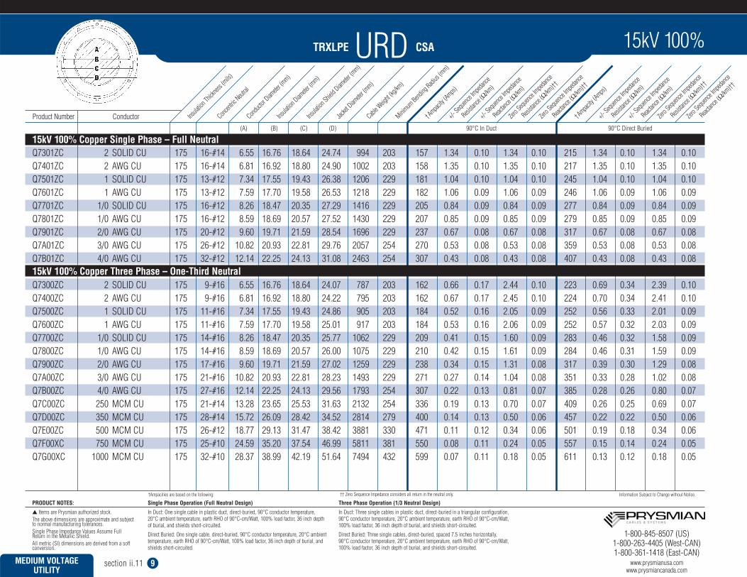
15kV 100% Aluminum Single Phase – Full Neutral
15kV 100% Aluminum Three Phase – One-Third Neutral
1-800-845-8507 (US)1-800-263-4405 (West-CAN)1-800-361-1418 (East-CAN)
www.prysmianusa.comwww.prysmiancanada.com
15kV 100%
†† Zero Sequence Impedance considers all return in the neutral only.
TRXLPE URD CSA
Single Phase Operation (Full Neutral Design)
In Duct: One single cable in plastic duct, direct-buried, 90°C conductor temperature, 20°C ambient temperature, earth RHO of 90°C-cm/Watt, 100% load factor, 36 inch depthof burial, and shields short-circuited.
Direct Buried: One single cable, direct-buried, 90°C conductor temperature, 20°C ambienttemperature, earth RHO of 90°C-cm/Watt, 100% load factor, 36 inch depth of burial, andshields short-circuited.
Three Phase Operation (1/3 Neutral Design)
In Duct: Three single cables in plastic duct, direct-buried in a triangular configuration,90°C conductor temperature, 20°C ambient temperature, earth RHO of 90°C-cm/Watt,100% load factor, 36 inch depth of burial, and shields short-circuited.
Direct Buried: Three single cables, direct-buried, spaced 7.5 inches horizontally, 90°C conductor temperature, 20°C ambient temperature, earth RHO of 90°C-cm/Watt,100% load factor, 36 inch depth of burial, and shields short-circuited.
PRODUCT NOTES:
Items are Prysmian authorized stock.The above dimensions are approximate and subjectto normal manufacturing tolerances.Single Phase Impedance Values Assume Full Return in the Metallic Shield.All metric (SI) dimensions are derived from a softconversion.
†Ampacities are based on the following: Information Subject to Change without Notice.
MEDIUM VOLTAGE UTILITY
section ii.11 9
(A) (B) (C) (D) 90°C In Duct 90°C Direct Buried
Q7301ZC 2 SOLID CU 175 16-#14 6.55 16.76 18.64 24.74 994 203 157 1.34 0.10 1.34 0.10 215 1.34 0.10 1.34 0.10Q7401ZC 2 AWG CU 175 16-#14 6.81 16.92 18.80 24.90 1002 203 158 1.35 0.10 1.35 0.10 217 1.35 0.10 1.35 0.10Q7501ZC 1 SOLID CU 175 13-#12 7.34 17.55 19.43 26.38 1206 229 181 1.04 0.10 1.04 0.10 245 1.04 0.10 1.04 0.10Q7601ZC 1 AWG CU 175 13-#12 7.59 17.70 19.58 26.53 1218 229 182 1.06 0.09 1.06 0.09 246 1.06 0.09 1.06 0.09Q7701ZC 1/0 SOLID CU 175 16-#12 8.26 18.47 20.35 27.29 1416 229 205 0.84 0.09 0.84 0.09 277 0.84 0.09 0.84 0.09Q7801ZC 1/0 AWG CU 175 16-#12 8.59 18.69 20.57 27.52 1430 229 207 0.85 0.09 0.85 0.09 279 0.85 0.09 0.85 0.09Q7901ZC 2/0 AWG CU 175 20-#12 9.60 19.71 21.59 28.54 1696 229 237 0.67 0.08 0.67 0.08 317 0.67 0.08 0.67 0.08Q7A01ZC 3/0 AWG CU 175 26-#12 10.82 20.93 22.81 29.76 2057 254 270 0.53 0.08 0.53 0.08 359 0.53 0.08 0.53 0.08Q7B01ZC 4/0 AWG CU 175 32-#12 12.14 22.25 24.13 31.08 2463 254 307 0.43 0.08 0.43 0.08 407 0.43 0.08 0.43 0.08
Q7300ZC 2 SOLID CU 175 9-#16 6.55 16.76 18.64 24.07 787 203 162 0.66 0.17 2.44 0.10 223 0.69 0.34 2.39 0.10Q7400ZC 2 AWG CU 175 9-#16 6.81 16.92 18.80 24.22 795 203 162 0.67 0.17 2.45 0.10 224 0.70 0.34 2.41 0.10Q7500ZC 1 SOLID CU 175 11-#16 7.34 17.55 19.43 24.86 905 203 184 0.52 0.16 2.05 0.09 252 0.56 0.33 2.01 0.09Q7600ZC 1 AWG CU 175 11-#16 7.59 17.70 19.58 25.01 917 203 184 0.53 0.16 2.06 0.09 252 0.57 0.32 2.03 0.09Q7700ZC 1/0 SOLID CU 175 14-#16 8.26 18.47 20.35 25.77 1062 229 209 0.41 0.15 1.60 0.09 283 0.46 0.32 1.58 0.09Q7800ZC 1/0 AWG CU 175 14-#16 8.59 18.69 20.57 26.00 1075 229 210 0.42 0.15 1.61 0.09 284 0.46 0.31 1.59 0.09Q7900ZC 2/0 AWG CU 175 17-#16 9.60 19.71 21.59 27.02 1259 229 238 0.34 0.15 1.31 0.08 317 0.39 0.30 1.29 0.08Q7A00ZC 3/0 AWG CU 175 21-#16 10.82 20.93 22.81 28.23 1493 229 271 0.27 0.14 1.04 0.08 351 0.33 0.28 1.02 0.08Q7B00ZC 4/0 AWG CU 175 27-#16 12.14 22.25 24.13 29.56 1793 254 307 0.22 0.13 0.81 0.07 385 0.28 0.26 0.80 0.07Q7C00ZC 250 MCM CU 175 21-#14 13.28 23.65 25.53 31.63 2132 254 336 0.19 0.13 0.70 0.07 409 0.26 0.25 0.69 0.07Q7D00ZC 350 MCM CU 175 28-#14 15.72 26.09 28.42 34.52 2814 279 400 0.14 0.13 0.50 0.06 457 0.22 0.22 0.50 0.06Q7E00ZC 500 MCM CU 175 26-#12 18.77 29.13 31.47 38.42 3881 330 471 0.11 0.12 0.34 0.06 501 0.19 0.18 0.34 0.06Q7F00XC 750 MCM CU 175 25-#10 24.59 35.20 37.54 46.99 5811 381 550 0.08 0.11 0.24 0.05 557 0.15 0.14 0.24 0.05Q7G00XC 1000 MCM CU 175 32-#10 28.37 38.99 42.19 51.64 7494 432 599 0.07 0.11 0.18 0.05 611 0.13 0.12 0.18 0.05
Insula
tion Th
icknes
s (mils)
Concent
ric Neut
ralCond
uctor
Diamete
r (mm)
Insula
tion Diam
eter (m
m)Ins
ulation
Shield D
iamete
r (mm)
Jacket
Diamete
r (mm)
Cable W
eight (
kg/km
)Minim
um Bend
ing Radi
us (m
m)
†Ampacity
(Amps)+/-
Sequenc
e Imped
ance
Resista
nce (Ω
/km)
+/- Sequ
ence Im
pedanc
e
Reactan
ce (Ω
/km)
Zero S
equenc
e Imped
ance
Resista
nce (Ω
/km)††
Zero S
equenc
e Imped
ance
Reactan
ce (Ω
/km)††
+/- Sequ
ence Im
pedanc
e
Resista
nce (Ω
/km)
+/- Sequ
ence Im
pedanc
e
Reactan
ce (Ω
/km)
Zero S
equenc
e Imped
ance
Resista
nce (Ω
/km)††
Zero S
equenc
e Imped
ance
Reactan
ce (Ω
/km)††
†Ampacity
(Amps)
Product Number Conductor
15kV 100% Copper Single Phase – Full Neutral
15kV 100% Copper Three Phase – One-Third Neutral
1-800-845-8507 (US)1-800-263-4405 (West-CAN)1-800-361-1418 (East-CAN)
www.prysmianusa.comwww.prysmiancanada.com
15kV 100%
†† Zero Sequence Impedance considers all return in the neutral only.
TRXLPE URD CSA
Single Phase Operation (Full Neutral Design)
In Duct: One single cable in plastic duct, direct-buried, 90°C conductor temperature, 20°C ambient temperature, earth RHO of 90°C-cm/Watt, 100% load factor, 36 inch depthof burial, and shields short-circuited.
Direct Buried: One single cable, direct-buried, 90°C conductor temperature, 20°C ambienttemperature, earth RHO of 90°C-cm/Watt, 100% load factor, 36 inch depth of burial, andshields short-circuited.
Three Phase Operation (1/3 Neutral Design)
In Duct: Three single cables in plastic duct, direct-buried in a triangular configuration,90°C conductor temperature, 20°C ambient temperature, earth RHO of 90°C-cm/Watt,100% load factor, 36 inch depth of burial, and shields short-circuited.
Direct Buried: Three single cables, direct-buried, spaced 7.5 inches horizontally, 90°C conductor temperature, 20°C ambient temperature, earth RHO of 90°C-cm/Watt,100% load factor, 36 inch depth of burial, and shields short-circuited.
PRODUCT NOTES:
Items are Prysmian authorized stock.The above dimensions are approximate and subjectto normal manufacturing tolerances.Single Phase Impedance Values Assume Full Return in the Metallic Shield.All metric (SI) dimensions are derived from a softconversion.
†Ampacities are based on the following: Information Subject to Change without Notice.
MEDIUM VOLTAGE UTILITY
section ii.11 10
(A) (B) (C) (D) 90°C In Duct 90°C Direct Buried
Q8L01ZC 2 SOLID AL 220 10-#14 6.55 19.10 20.98 27.08 769 229 123 2.17 0.10 2.17 0.10 169 2.17 0.10 2.17 0.10Q8M01ZC 2 AWG AL 220 10-#14 6.81 19.25 21.13 27.23 776 229 124 2.20 0.10 2.20 0.10 170 2.20 0.10 2.20 0.10Q8N01ZC 1 SOLID AL 220 13-#14 7.34 19.89 21.77 27.87 869 229 141 1.70 0.09 1.70 0.09 193 1.70 0.09 1.70 0.09Q8O01ZC 1 AWG AL 220 13-#14 7.65 20.09 21.97 28.07 878 229 143 1.72 0.09 1.72 0.09 194 1.72 0.09 1.72 0.09Q8P01ZC 1/0 SOLID AL 220 16-#14 8.26 20.80 22.68 28.78 9779 254 160 1.36 0.09 1.36 0.09 219 1.36 0.09 1.36 0.09Q8Q01ZC 1/0 AWG AL 220 16-#14 8.59 21.03 22.91 29.01 990 254 162 1.38 0.09 1.38 0.09 220 1.38 0.09 1.38 0.09Q8R01ZC 2/0 AWG AL 220 13-#12 9.60 22.05 23.93 30.88 1179 254 186 1.08 0.08 1.08 0.08 251 1.08 0.08 1.08 0.08Q8S01ZC 3/0 AWG AL 220 16-#12 10.82 23.27 25.15 32.10 1351 279 212 0.86 0.08 0.86 0.08 284 0.86 0.08 0.86 0.08Q8T01ZC 4/0 AWG AL 220 20-#12 12.14 24.59 26.47 33.42 1516 279 241 0.69 0.07 0.69 0.07 323 0.69 0.07 0.69 0.07Q8U01ZC 250 MCM AL 220 23-#12 13.28 25.98 27.86 34.81 1784 279 270 0.56 0.07 0.56 0.07 358 0.56 0.07 0.56 0.07Q8V01ZC 350 MCM AL 220 33-#12 15.72 28.42 30.76 37.71 2330 305 321 0.42 0.07 0.42 0.07 422 0.42 0.07 0.42 0.07
Q8L00ZC 2 SOLID AL 220 9-#16 6.55 19.10 20.98 26.41 665 229 127 1.08 0.17 3.02 0.11 174 1.11 0.34 2.96 0.11Q8M00ZC 2 AWG AL 220 9-#16 6.81 19.25 21.13 26.56 672 229 127 1.10 0.17 3.04 0.11 174 1.13 0.34 2.99 0.11Q8N00ZC 1 SOLID AL 220 9-#16 7.34 19.89 21.77 27.19 712 229 144 0.86 0.17 2.80 0.10 198 0.88 0.33 2.75 0.10Q8O00ZC 1 AWG AL 220 9-#16 7.65 20.09 21.97 27.40 720 229 145 0.87 0.16 2.82 0.10 198 0.90 0.32 2.77 0.10Q8P00ZC 1/0 SOLID AL 220 9-#16 8.26 20.80 22.68 28.11 768 229 164 0.68 0.16 2.63 0.10 224 0.70 0.32 2.58 0.10Q8Q00ZC 1/0 AWG AL 220 10-#16 8.59 21.03 22.91 28.34 789 229 165 0.70 0.16 2.45 0.09 224 0.72 0.31 2.41 0.09Q8R00ZC 2/0 AWG AL 220 11-#16 9.60 22.05 23.93 29.35 868 254 187 0.55 0.15 2.15 0.09 254 0.58 0.31 2.11 0.09Q8S00ZC 3/0 AWG AL 220 14-#16 10.82 23.27 25.15 30.57 985 254 214 0.44 0.14 1.69 0.08 286 0.47 0.29 1.67 0.08Q8T00ZC 4/0 AWG AL 220 17-#16 12.14 24.59 26.47 31.89 1068 279 243 0.35 0.14 1.39 0.08 320 0.39 0.28 1.37 0.08Q8U00ZC 250 MCM AL 220 21-#16 13.28 25.98 27.86 33.29 1273 279 266 0.30 0.13 1.13 0.07 345 0.34 0.27 1.12 0.07Q8V00ZC 350 MCM AL 220 27-#16 15.72 28.42 30.76 36.18 1586 305 321 0.21 0.13 0.87 0.07 401 0.27 0.25 0.86 0.07Q8W00ZC 500 MCM AL 220 25-#14 18.80 31.50 33.83 39.93 2080 330 387 0.16 0.12 0.58 0.06 454 0.22 0.22 0.58 0.06Q8X00ZC 750 MCM AL 220 24-#12 23.11 36.07 38.40 46.78 2986 381 471 0.11 0.12 0.39 0.06 511 0.18 0.19 0.39 0.06Q8Y00ZC 1000 MCM AL 220 31-#12 26.92 39.88 43.08 51.45 3744 432 534 0.09 0.11 0.30 0.05 554 0.16 0.16 0.30 0.05
Insula
tion Th
icknes
s (mils)
Concent
ric Neut
ralCond
uctor
Diamete
r (mm)
Insula
tion Diam
eter (m
m)Ins
ulation
Shield D
iamete
r (mm)
Jacket
Diamete
r (mm)
Cable W
eight (
kg/km
)Minim
um Bend
ing Radi
us (m
m)
†Ampacity
(Amps)+/-
Sequenc
e Imped
ance
Resista
nce (Ω
/km)
+/- Sequ
ence Im
pedanc
e
Reactan
ce (Ω
/km)
Zero S
equenc
e Imped
ance
Resista
nce (Ω
/km)††
Zero S
equenc
e Imped
ance
Reactan
ce (Ω
/km)††
+/- Sequ
ence Im
pedanc
e
Resista
nce (Ω
/km)
+/- Sequ
ence Im
pedanc
e
Reactan
ce (Ω
/km)
Zero S
equenc
e Imped
ance
Resista
nce (Ω
/km)††
Zero S
equenc
e Imped
ance
Reactan
ce (Ω
/km)††
†Ampacity
(Amps)
Product Number Conductor
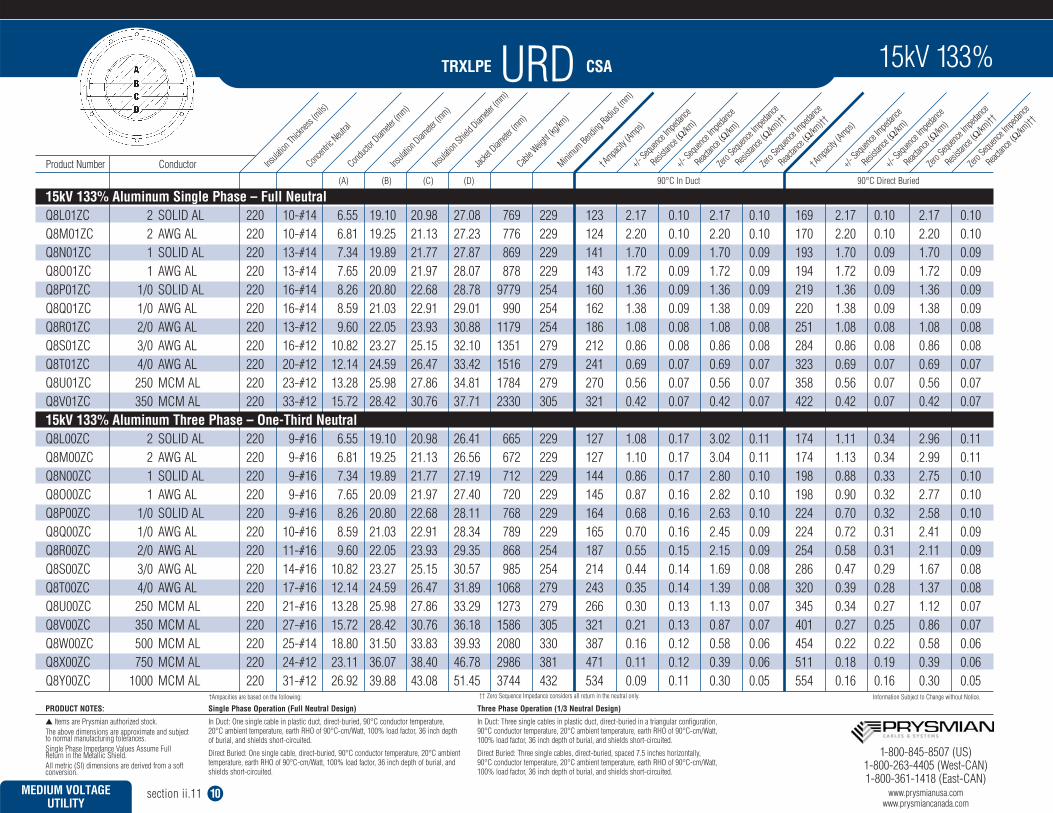
15kV 133% Aluminum Single Phase – Full Neutral
15kV 133% Aluminum Three Phase – One-Third Neutral
1-800-845-8507 (US)1-800-263-4405 (West-CAN)1-800-361-1418 (East-CAN)
www.prysmianusa.comwww.prysmiancanada.com
15kV 133%
†† Zero Sequence Impedance considers all return in the neutral only.

TRXLPE URD CSA
Single Phase Operation (Full Neutral Design)
In Duct: One single cable in plastic duct, direct-buried, 90°C conductor temperature, 20°C ambient temperature, earth RHO of 90°C-cm/Watt, 100% load factor, 36 inch depthof burial, and shields short-circuited.
Direct Buried: One single cable, direct-buried, 90°C conductor temperature, 20°C ambienttemperature, earth RHO of 90°C-cm/Watt, 100% load factor, 36 inch depth of burial, andshields short-circuited.
Three Phase Operation (1/3 Neutral Design)
In Duct: Three single cables in plastic duct, direct-buried in a triangular configuration,90°C conductor temperature, 20°C ambient temperature, earth RHO of 90°C-cm/Watt,100% load factor, 36 inch depth of burial, and shields short-circuited.
Direct Buried: Three single cables, direct-buried, spaced 7.5 inches horizontally, 90°C conductor temperature, 20°C ambient temperature, earth RHO of 90°C-cm/Watt,100% load factor, 36 inch depth of burial, and shields short-circuited.
PRODUCT NOTES:
Items are Prysmian authorized stock.The above dimensions are approximate and subjectto normal manufacturing tolerances.Single Phase Impedance Values Assume Full Return in the Metallic Shield.All metric (SI) dimensions are derived from a softconversion.
†Ampacities are based on the following: Information Subject to Change without Notice.
MEDIUM VOLTAGE UTILITY
section ii.11 11
(A) (B) (C) (D) 90°C In Duct 90°C Direct Buried
Q8301ZC 2 SOLID CU 220 16-#14 6.55 19.10 20.98 27.08 1082 229 157 1.34 0.10 1.34 0.10 215 1.34 0.10 1.34 0.10Q8401ZC 2 AWG CU 220 16-#14 6.81 19.25 21.13 27.23 1091 229 158 1.35 0.10 1.35 0.10 217 1.35 0.10 1.35 0.10Q8501ZC 1 SOLID CU 220 13-#12 7.34 19.89 21.77 28.72 1300 254 181 1.04 0.10 1.04 0.10 245 1.04 0.10 1.04 0.10Q8601ZC 1 AWG CU 220 13-#12 7.59 20.04 21.92 28.87 1312 254 182 1.06 0.09 1.06 0.09 246 1.06 0.09 1.06 0.09Q8701ZC 1/0 SOLID CU 220 16-#12 8.26 20.80 22.68 29.63 1513 254 205 0.84 0.09 0.84 0.09 277 0.84 0.09 0.84 0.09Q8801ZC 1/0 AWG CU 220 16-#12 8.59 21.03 22.91 29.86 1528 254 207 0.85 0.09 0.85 0.09 279 0.85 0.09 0.85 0.09Q8901ZC 2/0 AWG CU 220 20-#12 9.60 22.05 23.93 30.88 1797 254 237 0.67 0.08 0.67 0.08 317 0.67 0.08 0.67 0.08Q8A01ZC 3/0 AWG CU 220 26-#12 10.82 23.27 25.15 32.10 2163 279 270 0.53 0.08 0.53 0.08 359 0.53 0.08 0.53 0.08Q8B01ZC 4/0 AWG CU 220 32-#12 12.14 24.59 26.47 33.42 2573 279 307 0.43 0.08 0.43 0.08 407 0.43 0.08 0.43 0.08
Q8300ZC 2 SOLID CU 220 9-#16 6.55 19.10 20.98 26.41 873 229 162 0.66 0.17 2.44 0.10 223 0.69 0.34 2.39 0.10Q8400ZC 2 AWG CU 220 9-#16 6.81 19.25 21.13 26.56 882 229 162 0.67 0.17 2.45 0.10 224 0.70 0.34 2.41 0.10Q8500ZC 1 SOLID CU 220 11-#16 7.34 19.89 21.77 27.19 994 229 184 0.52 0.16 2.05 0.09 252 0.56 0.33 2.01 0.09Q8600ZC 1 AWG CU 220 11-#16 7.59 20.04 21.92 27.35 1006 229 184 0.53 0.16 2.06 0.09 252 0.57 0.32 2.03 0.09Q8700ZC 1/0 SOLID CU 220 14-#16 8.26 20.80 22.68 28.11 1154 229 209 0.41 0.15 1.60 0.09 283 0.46 0.32 1.58 0.09Q8800ZC 1/0 AWG CU 220 14-#16 8.59 21.03 22.91 28.34 1167 229 210 0.42 0.15 1.61 0.09 284 0.46 0.31 1.59 0.09Q8900ZC 2/0 AWG CU 220 17-#16 9.60 22.05 23.93 29.35 1355 254 238 0.34 0.15 1.31 0.08 317 0.39 0.30 1.29 0.08Q8A00ZC 3/0 AWG CU 220 21-#16 10.82 23.27 25.15 30.57 1593 254 271 0.27 0.14 1.04 0.08 351 0.33 0.28 1.02 0.08Q8B00ZC 4/0 AWG CU 220 27-#16 12.14 24.59 26.47 31.89 1897 279 307 0.22 0.13 0.81 0.07 385 0.28 0.26 0.80 0.07Q8C00ZC 250 MCM CU 220 21-#14 13.28 25.98 27.86 33.96 2244 279 336 0.19 0.13 0.70 0.07 409 0.26 0.25 0.69 0.07Q8D00ZC 350 MCM CU 220 28-#14 15.72 28.42 30.76 36.86 2936 305 400 0.14 0.13 0.50 0.06 457 0.22 0.22 0.50 0.06Q8E00ZC 500 MCM CU 220 26-#12 18.77 31.47 33.81 40.76 4017 330 471 0.11 0.12 0.34 0.06 501 0.19 0.18 0.34 0.06Q8F00XC 750 MCM CU 220 25-#10 24.59 37.54 39.88 49.33 5975 406 550 0.08 0.11 0.24 0.05 557 0.15 0.14 0.24 0.05Q8G00XC 1000 MCM CU 220 32-#10 28.37 41.33 44.53 53.98 7674 432 599 0.07 0.11 0.18 0.05 611 0.13 0.12 0.18 0.05
Insula
tion Th
icknes
s (mils)
Concent
ric Neut
ralCond
uctor
Diamete
r (mm)
Insula
tion Diam
eter (m
m)Ins
ulation
Shield D
iamete
r (mm)
Jacket
Diamete
r (mm)
Cable W
eight (
kg/km
)Minim
um Bend
ing Radi
us (m
m)
†Ampacity
(Amps)+/-
Sequenc
e Imped
ance
Resista
nce (Ω
/km)
+/- Sequ
ence Im
pedanc
e
Reactan
ce (Ω
/km)
Zero S
equenc
e Imped
ance
Resista
nce (Ω
/km)††
Zero S
equenc
e Imped
ance
Reactan
ce (Ω
/km)††
+/- Sequ
ence Im
pedanc
e
Resista
nce (Ω
/km)
+/- Sequ
ence Im
pedanc
e
Reactan
ce (Ω
/km)
Zero S
equenc
e Imped
ance
Resista
nce (Ω
/km)††
Zero S
equenc
e Imped
ance
Reactan
ce (Ω
/km)††
†Ampacity
(Amps)
Product Number Conductor
15kV 133% Copper Single Phase – Full Neutral
15kV 133% Copper Three Phase – One-Third Neutral
1-800-845-8507 (US)1-800-263-4405 (West-CAN)1-800-361-1418 (East-CAN)
www.prysmianusa.comwww.prysmiancanada.com
15kV 133%
†† Zero Sequence Impedance considers all return in the neutral only.

TRXLPE URD CSA
Single Phase Operation (Full Neutral Design)
In Duct: One single cable in plastic duct, direct-buried, 90°C conductor temperature, 20°C ambient temperature, earth RHO of 90°C-cm/Watt, 100% load factor, 36 inch depthof burial, and shields short-circuited.
Direct Buried: One single cable, direct-buried, 90°C conductor temperature, 20°C ambienttemperature, earth RHO of 90°C-cm/Watt, 100% load factor, 36 inch depth of burial, andshields short-circuited.
Three Phase Operation (1/3 Neutral Design)
In Duct: Three single cables in plastic duct, direct-buried in a triangular configuration,90°C conductor temperature, 20°C ambient temperature, earth RHO of 90°C-cm/Watt,100% load factor, 36 inch depth of burial, and shields short-circuited.
Direct Buried: Three single cables, direct-buried, spaced 7.5 inches horizontally, 90°C conductor temperature, 20°C ambient temperature, earth RHO of 90°C-cm/Watt,100% load factor, 36 inch depth of burial, and shields short-circuited.
PRODUCT NOTES:
Items are Prysmian authorized stock.The above dimensions are approximate and subjectto normal manufacturing tolerances.Single Phase Impedance Values Assume Full Return in the Metallic Shield.All metric (SI) dimensions are derived from a softconversion.
†Ampacities are based on the following: Information Subject to Change without Notice.
MEDIUM VOLTAGE UTILITY
section ii.11 12
(A) (B) (C) (D) 90°C In Duct 90°C Direct Buried
Q9N01ZC 1 SOLID AL 260 13-#14 7.34 21.97 23.85 29.95 957 254 145 1.70 0.11 1.70 0.11 192 1.70 0.11 1.70 0.11Q9O01ZC 1 AWG AL 260 13-#14 7.65 22.17 24.05 30.15 966 254 146 1.72 0.10 1.72 0.11 194 1.72 0.10 1.72 0.11Q9P01ZC 1/0 SOLID AL 260 16-#14 8.26 22.89 24.77 30.87 1070 254 165 1.36 0.10 1.36 0.10 218 1.36 0.10 1.36 0.10Q9Q01ZC 1/0 AWG AL 260 16-#14 8.59 23.11 24.99 31.09 1081 254 166 1.38 0.10 1.38 0.10 219 1.38 0.10 1.38 0.10Q9R01ZC 2/0 AWG AL 260 13-#12 9.60 24.13 26.01 32.96 1276 279 190 1.08 0.09 1.08 0.10 250 1.08 0.09 1.08 0.10Q9S01ZC 3/0 AWG AL 260 16-#12 10.82 25.35 27.23 34.18 1451 279 217 0.86 0.09 0.86 0.09 283 0.86 0.09 0.86 0.09Q9T01ZC 4/0 AWG AL 260 20-#12 12.14 26.67 29.01 35.96 1652 305 247 0.69 0.09 0.69 0.09 322 0.69 0.09 0.69 0.09Q9U01ZC 250 MCM AL 260 23-#12 13.28 28.07 30.40 37.35 1926 305 276 0.56 0.08 0.56 0.08 356 0.56 0.08 0.56 0.08Q9V01ZC 350 MCM AL 260 33-#12 15.72 30.51 32.84 39.79 2448 330 326 0.42 0.08 0.42 0.08 418 0.42 0.08 0.42 0.08
Q9N00ZC 1 SOLID AL 260 10-#16 7.34 21.97 23.85 29.28 808 254 146 0.86 0.17 2.60 0.11 196 0.88 0.33 2.53 0.11Q9O00ZC 1 AWG AL 260 10-#16 7.65 22.17 24.05 29.48 818 254 146 0.87 0.17 2.62 0.10 197 0.90 0.32 2.57 0.10Q9P00ZC 1/0 SOLID AL 260 10-#16 8.26 22.89 24.77 30.19 867 254 166 0.68 0.16 2.43 0.10 223 0.71 0.32 2.38 0.10Q9Q00ZC 1/0 AWG AL 260 10-#16 8.59 23.11 24.99 30.42 878 254 166 0.70 0.16 2.45 0.10 223 0.72 0.31 2.40 0.10Q9R00ZC 2/0 AWG AL 260 11-#16 9.60 24.13 26.01 31.44 960 254 189 0.55 0.16 2.15 0.09 252 0.58 0.31 2.11 0.09Q9S00ZC 3/0 AWG AL 260 14-#16 10.82 25.35 27.23 32.65 1081 279 215 0.44 0.15 1.69 0.09 284 0.47 0.29 1.66 0.09Q9T00ZC 4/0 AWG AL 260 17-#16 12.14 26.67 29.01 34.43 1198 279 244 0.35 0.15 1.38 0.08 318 0.39 0.28 1.36 0.08Q9U00ZC 250 MCM AL 260 21-#16 13.28 28.07 30.40 35.83 1408 305 268 0.30 0.14 1.13 0.08 344 0.34 0.27 1.12 0.08Q9V00ZC 350 MCM AL 260 27-#16 15.72 30.51 32.84 38.27 1699 330 322 0.21 0.13 0.86 0.07 400 0.27 0.25 0.85 0.07Q9W00ZC 500 MCM AL 260 25-#14 18.80 33.58 35.92 43.44 2283 356 389 0.16 0.13 0.58 0.07 453 0.22 0.23 0.58 0.07Q9X00ZC 750 MCM AL 260 24-#12 23.11 38.15 40.49 48.86 3131 406 473 0.11 0.12 0.39 0.06 514 0.18 0.19 0.39 0.06Q9Y00ZC 1000 MCM AL 260 31-#12 26.92 41.96 45.16 53.53 3903 432 535 0.09 0.12 0.30 0.06 557 0.16 0.16 0.30 0.06
Insula
tion Th
icknes
s (mils)
Concent
ric Neut
ralCond
uctor
Diamete
r (mm)
Insula
tion Diam
eter (m
m)Ins
ulation
Shield D
iamete
r (mm)
Jacket
Diamete
r (mm)
Cable W
eight (
kg/km
)Minim
um Bend
ing Radi
us (m
m)
†Ampacity
(Amps)+/-
Sequenc
e Imped
ance
Resista
nce (Ω
/km)
+/- Sequ
ence Im
pedanc
e
Reactan
ce (Ω
/km)
Zero S
equenc
e Imped
ance
Resista
nce (Ω
/km)††
Zero S
equenc
e Imped
ance
Reactan
ce (Ω
/km)††
+/- Sequ
ence Im
pedanc
e
Resista
nce (Ω
/km)
+/- Sequ
ence Im
pedanc
e
Reactan
ce (Ω
/km)
Zero S
equenc
e Imped
ance
Resista
nce (Ω
/km)††
Zero S
equenc
e Imped
ance
Reactan
ce (Ω
/km)††
†Ampacity
(Amps)
Product Number Conductor
25kV 100% Aluminum Single Phase – Full Neutral
25kV 100% Aluminum Three Phase – One-Third Neutral
1-800-845-8507 (US)1-800-263-4405 (West-CAN)1-800-361-1418 (East-CAN)
www.prysmianusa.comwww.prysmiancanada.com
25kV 100%
†† Zero Sequence Impedance considers all return in the neutral only.

TRXLPE URD CSA
Single Phase Operation (Full Neutral Design)
In Duct: One single cable in plastic duct, direct-buried, 90°C conductor temperature, 20°C ambient temperature, earth RHO of 90°C-cm/Watt, 100% load factor, 36 inch depthof burial, and shields short-circuited.
Direct Buried: One single cable, direct-buried, 90°C conductor temperature, 20°C ambienttemperature, earth RHO of 90°C-cm/Watt, 100% load factor, 36 inch depth of burial, andshields short-circuited.
Three Phase Operation (1/3 Neutral Design)
In Duct: Three single cables in plastic duct, direct-buried in a triangular configuration,90°C conductor temperature, 20°C ambient temperature, earth RHO of 90°C-cm/Watt,100% load factor, 36 inch depth of burial, and shields short-circuited.
Direct Buried: Three single cables, direct-buried, spaced 7.5 inches horizontally, 90°C conductor temperature, 20°C ambient temperature, earth RHO of 90°C-cm/Watt,100% load factor, 36 inch depth of burial, and shields short-circuited.
PRODUCT NOTES:
Items are Prysmian authorized stock.The above dimensions are approximate and subjectto normal manufacturing tolerances.Single Phase Impedance Values Assume Full Return in the Metallic Shield.All metric (SI) dimensions are derived from a softconversion.
†Ampacities are based on the following: Information Subject to Change without Notice.
MEDIUM VOLTAGE UTILITY
section ii.11 13
(A) (B) (C) (D) 90°C In Duct 90°C Direct Buried
Q9501ZC 1 SOLID CU 260 13-#12 7.34 21.97 23.85 30.80 1390 254 186 1.04 0.11 1.04 0.11 245 1.04 0.11 1.04 0.11Q9601ZC 1 AWG CU 260 13-#12 7.59 22.12 24.00 30.95 1403 254 187 1.06 0.11 1.06 0.11 246 1.06 0.11 1.06 0.11Q9701ZC 1/0 SOLID CU 260 16-#12 8.26 22.89 24.77 31.71 1607 254 210 0.84 0.10 0.84 0.10 277 0.84 0.10 0.84 0.10Q9801ZC 1/0 AWG CU 260 16-#12 8.59 23.11 24.99 31.94 1621 279 212 0.85 0.10 0.85 0.10 279 0.85 0.10 0.85 0.10Q9901ZC 2/0 AWG CU 260 20-#12 9.60 24.13 26.01 32.96 1895 279 243 0.67 0.10 0.67 0.10 317 0.67 0.10 0.67 0.10Q9A01ZC 3/0 AWG CU 260 26-#12 10.82 25.35 27.23 34.18 2264 279 276 0.53 0.09 0.53 0.09 359 0.53 0.09 0.53 0.09Q9B01ZC 4/0 AWG CU 260 32-#12 12.14 26.67 29.01 35.96 2710 305 314 0.43 0.09 0.43 0.09 406 0.43 0.09 0.43 0.09
Q9500ZC 1 SOLID CU 260 11-#16 7.34 21.97 23.85 29.28 1079 254 187 0.52 0.17 2.04 0.11 249 0.55 0.33 2.00 0.11Q9600ZC 1 AWG CU 260 11-#16 7.59 22.12 24.00 29.43 1092 254 187 0.53 0.17 2.05 0.11 249 0.56 0.32 2.01 0.11Q9700ZC 1/0 SOLID CU 260 14-#16 8.26 22.89 24.77 30.19 1242 254 213 0.41 0.17 1.60 0.10 280 0.45 0.32 1.57 0.10Q9800ZC 1/0 AWG CU 260 14-#16 8.59 23.11 24.99 30.42 1256 254 213 0.42 0.16 1.61 0.10 281 0.46 0.31 1.58 0.10Q9900ZC 2/0 AWG CU 260 17-#16 9.60 24.13 26.01 31.44 1447 254 242 0.34 0.16 1.31 0.09 314 0.38 0.30 1.29 0.09Q9A00ZC 3/0 AWG CU 260 21-#16 10.82 25.35 27.23 32.65 1689 279 275 0.27 0.15 1.03 0.09 349 0.32 0.28 1.02 0.09Q9B00ZC 4/0 AWG CU 260 27-#16 12.14 26.67 29.01 34.43 2027 279 311 0.22 0.15 0.81 0.08 384 0.28 0.27 0.80 0.08Q9C00ZC 250 MCM CU 260 21-#14 13.28 28.07 30.40 36.50 2382 305 341 0.19 0.14 0.69 0.08 410 0.25 0.26 0.69 0.08Q9D00ZC 350 MCM CU 260 28-#14 15.72 30.51 32.84 38.94 3052 330 405 0.14 0.13 0.50 0.07 460 0.21 0.23 0.50 0.07Q9E00ZC 500 MCM CU 260 26-#12 18.77 33.55 35.89 44.26 4224 356 475 0.11 0.13 0.34 0.07 504 0.18 0.19 0.34 0.07Q9F00XC 750 MCM CU 260 25-#10 24.59 39.62 42.82 52.27 6201 432 557 0.08 0.12 0.24 0.06 566 0.15 0.15 0.24 0.06Q9G00XC 1000 MCM CU 260 32-#10 28.37 43.41 46.61 56.06 7842 457 606 0.07 0.11 0.18 0.06 618 0.13 0.12 0.18 0.06
Insula
tion Th
icknes
s (mils)
Concent
ric Neut
ralCond
uctor
Diamete
r (mm)
Insula
tion Diam
eter (m
m)Ins
ulation
Shield D
iamete
r (mm)
Jacket
Diamete
r (mm)
Cable W
eight (
kg/km
)Minim
um Bend
ing Radi
us (m
m)
†Ampacity
(Amps)+/-
Sequenc
e Imped
ance
Resista
nce (Ω
/km)
+/- Sequ
ence Im
pedanc
e
Reactan
ce (Ω
/km)
Zero S
equenc
e Imped
ance
Resista
nce (Ω
/km)††
Zero S
equenc
e Imped
ance
Reactan
ce (Ω
/km)††
+/- Sequ
ence Im
pedanc
e
Resista
nce (Ω
/km)
+/- Sequ
ence Im
pedanc
e
Reactan
ce (Ω
/km)
Zero S
equenc
e Imped
ance
Resista
nce (Ω
/km)††
Zero S
equenc
e Imped
ance
Reactan
ce (Ω
/km)††
†Ampacity
(Amps)
Product Number Conductor
25kV 100% Copper Single Phase – Full Neutral
25kV 100% Copper Three Phase – One-Third Neutral
1-800-845-8507 (US)1-800-263-4405 (West-CAN)1-800-361-1418 (East-CAN)
www.prysmianusa.comwww.prysmiancanada.com
25kV 100%
†† Zero Sequence Impedance considers all return in the neutral only.

TRXLPE URD CSA
Single Phase Operation (Full Neutral Design)
In Duct: One single cable in plastic duct, direct-buried, 90°C conductor temperature, 20°C ambient temperature, earth RHO of 90°C-cm/Watt, 100% load factor, 36 inch depthof burial, and shields short-circuited.
Direct Buried: One single cable, direct-buried, 90°C conductor temperature, 20°C ambienttemperature, earth RHO of 90°C-cm/Watt, 100% load factor, 36 inch depth of burial, andshields short-circuited.
Three Phase Operation (1/3 Neutral Design)
In Duct: Three single cables in plastic duct, direct-buried in a triangular configuration,90°C conductor temperature, 20°C ambient temperature, earth RHO of 90°C-cm/Watt,100% load factor, 36 inch depth of burial, and shields short-circuited.
Direct Buried: Three single cables, direct-buried, spaced 7.5 inches horizontally, 90°C conductor temperature, 20°C ambient temperature, earth RHO of 90°C-cm/Watt,100% load factor, 36 inch depth of burial, and shields short-circuited.
PRODUCT NOTES:
Items are Prysmian authorized stock.The above dimensions are approximate and subjectto normal manufacturing tolerances.Single Phase Impedance Values Assume Full Return in the Metallic Shield.All metric (SI) dimensions are derived from a softconversion.
†Ampacities are based on the following: Information Subject to Change without Notice.
MEDIUM VOLTAGE UTILITY
section ii.11 14
(A) (B) (C) (D) 90°C In Duct 90°C Direct Buried
QAN01ZC 1 SOLID AL 320 13-#14 7.34 25.12 27.00 33.10 1110 279 145 1.70 0.11 1.70 0.11 192 1.70 0.11 1.70 0.11QAO01ZC 1 AWG AL 320 13-#14 7.65 25.32 27.20 33.30 1112 279 146 1.72 0.10 1.72 0.11 194 1.72 0.10 1.72 0.11QAP01ZC 1/0 SOLID AL 320 16-#14 8.26 26.04 27.91 34.02 1218 279 165 1.36 0.10 1.36 0.10 218 1.36 0.10 1.36 0.10QAQ01ZC 1/0 AWG AL 320 16-#14 8.59 26.26 28.60 34.70 1261 279 166 1.38 0.10 1.38 0.10 219 1.38 0.10 1.38 0.10QAR01ZC 2/0 AWG AL 320 13-#12 9.60 27.28 29.62 36.57 1467 305 190 1.08 0.09 1.08 0.10 250 1.08 0.09 1.08 0.10QAS01ZC 3/0 AWG AL 320 16-#12 10.82 28.50 30.84 37.79 1648 305 217 0.86 0.09 0.86 0.09 283 0.86 0.09 0.86 0.09QAT01ZC 4/0 AWG AL 320 20-#12 12.14 29.82 32.16 39.11 1825 330 247 0.69 0.09 0.69 0.09 322 0.69 0.09 0.69 0.09QAU01ZC 250 MCM AL 320 23-#12 13.28 31.22 33.55 40.50 2105 330 276 0.56 0.08 0.56 0.08 356 0.56 0.08 0.56 0.08QAV01ZC 350 MCM AL 320 33-#12 15.72 33.66 35.99 44.36 2719 356 326 0.42 0.08 0.42 0.08 418 0.42 0.08 0.42 0.08
QAN00ZC 1 SOLID AL 320 11-#16 7.34 25.12 27.00 32.43 960 279 147 0.86 0.18 2.44 0.12 194 0.88 0.33 2.39 0.12QAO00ZC 1 AWG AL 320 11-#16 7.65 25.32 27.20 32.63 971 279 147 0.87 0.17 2.45 0.11 195 0.90 0.32 2.41 0.11QAP00ZC 1/0 SOLID AL 320 11-#16 8.26 26.04 27.91 33.34 1024 279 167 0.68 0.17 2.26 0.11 220 0.71 0.32 2.22 0.11QAQ00ZC 1/0 AWG AL 320 12-#16 8.59 26.26 28.60 34.03 1077 279 168 0.70 0.17 2.15 0.11 220 0.70 0.31 2.11 0.11QAR00ZC 2/0 AWG AL 320 12-#16 9.60 27.28 29.62 35.04 1153 305 191 0.55 0.16 2.30 0.10 250 0.57 0.31 2.25 0.10QAS00ZC 3/0 AWG AL 320 14-#16 10.82 28.50 30.84 36.26 1270 305 217 0.44 0.16 1.68 0.10 282 0.47 0.30 1.65 0.10QAT00ZC 4/0 AWG AL 320 17-#16 12.14 29.82 32.16 37.58 1363 305 246 0.35 0.15 1.38 0.09 316 0.38 0.28 1.36 0.09QAU00ZC 250 MCM AL 320 21-#16 13.28 31.22 33.55 38.98 1580 330 270 0.30 0.15 1.13 0.09 342 0.34 0.27 1.11 0.09QAV00ZC 350 MCM AL 320 27-#16 15.72 33.66 35.99 41.42 1882 356 324 0.21 0.14 0.86 0.08 399 0.26 0.26 0.85 0.08QAW00ZC 500 MCM AL 320 25-#14 18.80 36.73 39.07 46.59 2489 381 391 0.16 0.13 0.58 0.07 453 0.22 0.23 0.57 0.07QAX00ZC 750 MCM AL 320 24-#12 23.11 41.30 44.50 52.87 3436 432 476 0.11 0.13 0.39 0.07 517 0.18 0.19 0.39 0.07QAY00ZC 1000 MCM AL 320 31-#12 26.92 45.11 48.31 56.68 4156 457 538 0.09 0.12 0.30 0.06 561 0.16 0.17 0.30 0.06
Insula
tion Th
icknes
s (mils)
Concent
ric Neut
ralCond
uctor
Diamete
r (mm)
Insula
tion Diam
eter (m
m)Ins
ulation
Shield D
iamete
r (mm)
Jacket
Diamete
r (mm)
Cable W
eight (
kg/km
)Minim
um Bend
ing Radi
us (m
m)
†Ampacity
(Amps)+/-
Sequenc
e Imped
ance
Resista
nce (Ω
/km)
+/- Sequ
ence Im
pedanc
e
Reactan
ce (Ω
/km)
Zero S
equenc
e Imped
ance
Resista
nce (Ω
/km)††
Zero S
equenc
e Imped
ance
Reactan
ce (Ω
/km)††
+/- Sequ
ence Im
pedanc
e
Resista
nce (Ω
/km)
+/- Sequ
ence Im
pedanc
e
Reactan
ce (Ω
/km)
Zero S
equenc
e Imped
ance
Resista
nce (Ω
/km)††
Zero S
equenc
e Imped
ance
Reactan
ce (Ω
/km)††
†Ampacity
(Amps)
Product Number Conductor
25kV 133% Aluminum Single Phase – Full Neutral
25kV 133% Aluminum Three Phase – One-Third Neutral
1-800-845-8507 (US)1-800-263-4405 (West-CAN)1-800-361-1418 (East-CAN)
www.prysmianusa.comwww.prysmiancanada.com
25kV 133%
†† Zero Sequence Impedance considers all return in the neutral only.

TRXLPE URD CSA
Single Phase Operation (Full Neutral Design)
In Duct: One single cable in plastic duct, direct-buried, 90°C conductor temperature, 20°C ambient temperature, earth RHO of 90°C-cm/Watt, 100% load factor, 36 inch depthof burial, and shields short-circuited.
Direct Buried: One single cable, direct-buried, 90°C conductor temperature, 20°C ambienttemperature, earth RHO of 90°C-cm/Watt, 100% load factor, 36 inch depth of burial, andshields short-circuited.
Three Phase Operation (1/3 Neutral Design)
In Duct: Three single cables in plastic duct, direct-buried in a triangular configuration,90°C conductor temperature, 20°C ambient temperature, earth RHO of 90°C-cm/Watt,100% load factor, 36 inch depth of burial, and shields short-circuited.
Direct Buried: Three single cables, direct-buried, spaced 7.5 inches horizontally, 90°C conductor temperature, 20°C ambient temperature, earth RHO of 90°C-cm/Watt,100% load factor, 36 inch depth of burial, and shields short-circuited.
PRODUCT NOTES:
Items are Prysmian authorized stock.The above dimensions are approximate and subjectto normal manufacturing tolerances.Single Phase Impedance Values Assume Full Return in the Metallic Shield.All metric (SI) dimensions are derived from a softconversion.
†Ampacities are based on the following: Information Subject to Change without Notice.
MEDIUM VOLTAGE UTILITY
section ii.11 15
(A) (B) (C) (D) 90°C In Duct 90°C Direct Buried
QA501ZC 1 SOLID CU 320 13-#12 7.34 25.12 27.00 33.95 1539 279 186 1.04 0.11 1.04 0.11 245 1.04 0.11 1.04 0.11QA601ZC 1 AWG CU 320 13-#12 7.59 25.27 27.15 34.10 1552 279 187 1.06 0.11 1.06 0.11 246 1.06 0.11 1.06 0.11QA701ZC 1/0 SOLID CU 320 16-#12 8.26 26.04 27.91 34.86 1760 279 210 0.84 0.10 0.84 0.10 277 0.84 0.10 0.84 0.10QA801ZC 1/0 AWG CU 320 16-#12 8.59 26.26 28.60 35.55 1806 305 212 0.85 0.10 0.85 0.10 279 0.85 0.10 0.85 0.10QA901ZC 2/0 AWG CU 320 20-#12 9.60 27.28 29.62 36.57 2085 305 243 0.67 0.10 0.67 0.10 317 0.67 0.10 0.67 0.10QAA01ZC 3/0 AWG CU 320 26-#12 10.82 28.50 30.84 37.79 2461 305 276 0.53 0.09 0.53 0.09 359 0.53 0.09 0.53 0.09QAB01ZC 4/0 AWG CU 320 32-#12 12.14 29.82 32.16 39.11 2883 330 314 0.43 0.09 0.43 0.09 406 0.43 0.09 0.43 0.09
QA500ZC 1 SOLID CU 320 11-#16 7.34 25.12 27.00 32.43 1220 279 187 0.52 0.17 2.04 0.11 249 0.55 0.33 2.00 0.11QA600ZC 1 AWG CU 320 11-#16 7.59 25.27 27.15 32.58 1234 279 187 0.53 0.17 2.05 0.11 249 0.56 0.32 2.01 0.11QA700ZC 1/0 SOLID CU 320 14-#16 8.26 26.04 27.91 33.34 1388 279 213 0.41 0.17 1.60 0.10 280 0.45 0.32 1.57 0.10QA800ZC 1/0 AWG CU 320 14-#16 8.59 26.26 28.60 34.03 1433 279 213 0.42 0.16 1.61 0.10 281 0.46 0.31 1.58 0.10QA900ZC 2/0 AWG CU 320 17-#16 9.60 27.28 29.62 35.04 1628 305 242 0.34 0.16 1.31 0.09 314 0.38 0.30 1.29 0.09QAA00ZC 3/0 AWG CU 320 21-#16 10.82 28.50 30.84 36.26 1877 305 275 0.27 0.15 1.03 0.09 349 0.32 0.28 1.02 0.09QAB00ZC 4/0 AWG CU 320 27-#16 12.14 29.82 32.16 37.58 2193 305 311 0.22 0.15 0.81 0.08 384 0.28 0.27 0.80 0.08QAC00ZC 250 MCM CU 320 21-#14 13.28 31.22 33.55 39.65 2557 330 341 0.19 0.14 0.69 0.08 410 0.25 0.26 0.69 0.08QAD00ZC 350 MCM CU 320 28-#14 15.72 33.66 35.99 43.52 3317 356 405 0.14 0.13 0.50 0.07 460 0.21 0.23 0.50 0.07QAE00ZC 500 MCM CU 320 26-#12 18.77 36.70 39.04 47.41 4434 381 475 0.11 0.13 0.34 0.07 504 0.18 0.19 0.34 0.07QAF00XC 750 MCM CU 320 25-#10 24.59 42.77 45.97 55.42 6449 457 557 0.08 0.12 0.24 0.06 566 0.15 0.15 0.24 0.06QAG00XC 1000 MCM CU 320 32-#10 28.37 46.56 49.76 59.21 8107 483 606 0.07 0.11 0.18 0.06 618 0.13 0.12 0.18 0.06
Insula
tion Th
icknes
s (mils)
Concent
ric Neut
ralCond
uctor
Diamete
r (mm)
Insula
tion Diam
eter (m
m)Ins
ulation
Shield D
iamete
r (mm)
Jacket
Diamete
r (mm)
Cable W
eight (
kg/km
)Minim
um Bend
ing Radi
us (m
m)
†Ampacity
(Amps)+/-
Sequenc
e Imped
ance
Resista
nce (Ω
/km)
+/- Sequ
ence Im
pedanc
e
Reactan
ce (Ω
/km)
Zero S
equenc
e Imped
ance
Resista
nce (Ω
/km)††
Zero S
equenc
e Imped
ance
Reactan
ce (Ω
/km)††
+/- Sequ
ence Im
pedanc
e
Resista
nce (Ω
/km)
+/- Sequ
ence Im
pedanc
e
Reactan
ce (Ω
/km)
Zero S
equenc
e Imped
ance
Resista
nce (Ω
/km)††
Zero S
equenc
e Imped
ance
Reactan
ce (Ω
/km)††
†Ampacity
(Amps)
Product Number Conductor
25kV 133% Copper Single Phase – Full Neutral
25kV 133% Copper Three Phase – One-Third Neutral
1-800-845-8507 (US)1-800-263-4405 (West-CAN)1-800-361-1418 (East-CAN)
www.prysmianusa.comwww.prysmiancanada.com
25kV 133%
†† Zero Sequence Impedance considers all return in the neutral only.

TRXLPE URD CSA
Single Phase Operation (Full Neutral Design)
In Duct: One single cable in plastic duct, direct-buried, 90°C conductor temperature, 20°C ambient temperature, earth RHO of 90°C-cm/Watt, 100% load factor, 36 inch depthof burial, and shields short-circuited.
Direct Buried: One single cable, direct-buried, 90°C conductor temperature, 20°C ambienttemperature, earth RHO of 90°C-cm/Watt, 100% load factor, 36 inch depth of burial, andshields short-circuited.
Three Phase Operation (1/3 Neutral Design)
In Duct: Three single cables in plastic duct, direct-buried in a triangular configuration,90°C conductor temperature, 20°C ambient temperature, earth RHO of 90°C-cm/Watt,100% load factor, 36 inch depth of burial, and shields short-circuited.
Direct Buried: Three single cables, direct-buried, spaced 7.5 inches horizontally, 90°C conductor temperature, 20°C ambient temperature, earth RHO of 90°C-cm/Watt,100% load factor, 36 inch depth of burial, and shields short-circuited.
PRODUCT NOTES:
Items are Prysmian authorized stock.The above dimensions are approximate and subjectto normal manufacturing tolerances.Single Phase Impedance Values Assume Full Return in the Metallic Shield.All metric (SI) dimensions are derived from a softconversion.
†Ampacities are based on the following: Information Subject to Change without Notice.
MEDIUM VOLTAGE UTILITY
section ii.11 16
(A) (B) (C) (D) 90°C In Duct 90°C Direct Buried
QVN01ZC 1 SOLID AL 280 13-#14 7.34 23.04 24.92 31.02 1004 254 146 1.70 0.11 1.70 0.11 192 1.70 0.11 1.70 0.11QVO01ZC 1 AWG AL 280 13-#14 7.65 23.24 25.12 31.22 1014 254 146 1.72 0.11 1.72 0.11 192 1.72 0.11 1.72 0.11QVP01ZC 1/0 SOLID AL 280 16-#14 8.26 23.95 25.83 31.93 1118 279 165 1.36 0.10 1.36 0.11 218 1.36 0.10 1.36 0.11QVQ01ZC 1/0 AWG AL 280 16-#14 8.59 24.18 26.06 32.16 1130 279 165 1.38 0.10 1.38 0.11 217 1.38 0.10 1.38 0.11QVR01ZC 2/0 AWG AL 280 13-#12 9.60 25.20 27.08 34.03 1328 279 189 1.08 0.10 1.08 0.10 247 1.08 0.10 1.08 0.10QVS01ZC 3/0 AWG AL 280 16-#12 10.82 26.42 28.75 35.70 1526 305 216 0.86 0.10 0.86 0.10 281 0.86 0.10 0.86 0.10QVT01ZC 4/0 AWG AL 280 20-#12 12.14 27.74 30.07 37.02 1709 305 245 0.69 0.09 0.69 0.09 319 0.69 0.09 0.69 0.09QVU01ZC 250 MCM AL 280 23-#12 13.28 29.13 31.47 38.42 1985 330 268 0.59 0.09 0.59 0.09 348 0.59 0.09 0.59 0.09QVV01ZC 350 MCM AL 280 33-#12 15.72 31.57 33.91 40.86 2511 330 327 0.42 0.08 0.42 0.08 423 0.42 0.08 0.42 0.08
QVN00ZC 1 SOLID AL 280 10-#16 7.34 23.04 24.92 30.34 854 254 146 0.86 0.17 2.53 0.11 195 0.88 0.33 2.48 0.11QVO00ZC 1 AWG AL 280 10-#16 7.65 23.24 25.12 30.55 864 254 145 0.87 0.17 2.55 0.11 194 0.90 0.33 2.50 0.11QVP00ZC 1/0 SOLID AL 280 11-#16 8.26 23.95 25.83 31.26 926 254 166 0.68 0.17 2.20 0.11 221 0.71 0.32 2.16 0.11QVQ00ZC 1/0 AWG AL 280 11-#16 8.59 24.18 26.06 31.49 937 254 165 0.70 0.17 2.22 0.11 220 0.73 0.32 2.18 0.11QVR00ZC 2/0 AWG AL 280 11-#16 9.60 25.20 27.08 32.50 1010 279 188 0.55 0.16 2.08 0.10 249 0.58 0.31 2.04 0.10QVS00ZC 3/0 AWG AL 280 14-#16 10.82 26.42 28.75 34.18 1163 279 214 0.44 0.16 1.64 0.10 281 0.47 0.30 1.61 0.10QVT00ZC 4/0 AWG AL 280 17-#16 12.14 27.74 30.07 35.50 1252 305 243 0.35 0.15 1.34 0.09 314 0.39 0.29 1.32 0.09QVU00ZC 250 MCM AL 280 21-#16 13.28 29.13 31.47 36.90 1465 305 266 0.30 0.15 1.10 0.09 340 0.34 0.28 1.08 0.09QVV00ZC 350 MCM AL 280 27-#16 15.72 31.57 33.91 39.33 1759 330 320 0.21 0.14 0.84 0.08 395 0.27 0.26 0.83 0.08QVW00ZC 500 MCM AL 280 25-#14 18.80 34.65 36.98 44.51 2351 381 386 0.16 0.13 0.58 0.07 449 0.22 0.23 0.57 0.07QVX00ZC 750 MCM AL 280 24-#12 23.11 39.22 42.42 50.79 3279 406 470 0.11 0.13 0.38 0.07 509 0.18 0.19 0.38 0.07QVY00ZC 1000 MCM AL 280 31-#12 26.92 43.03 46.23 54.60 3987 457 531 0.09 0.12 0.29 0.06 552 0.16 0.17 0.29 0.06
Insula
tion Th
icknes
s (mils)
Concent
ric Neut
ralCond
uctor
Diamete
r (mm)
Insula
tion Diam
eter (m
m)Ins
ulation
Shield D
iamete
r (mm)
Jacket
Diamete
r (mm)
Cable W
eight (
kg/km
)Minim
um Bend
ing Radi
us (m
m)
†Ampacity
(Amps)+/-
Sequenc
e Imped
ance
Resista
nce (Ω
/km)
+/- Sequ
ence Im
pedanc
e
Reactan
ce (Ω
/km)
Zero S
equenc
e Imped
ance
Resista
nce (Ω
/km)††
Zero S
equenc
e Imped
ance
Reactan
ce (Ω
/km)††
+/- Sequ
ence Im
pedanc
e
Resista
nce (Ω
/km)
+/- Sequ
ence Im
pedanc
e
Reactan
ce (Ω
/km)
Zero S
equenc
e Imped
ance
Resista
nce (Ω
/km)††
Zero S
equenc
e Imped
ance
Reactan
ce (Ω
/km)††
†Ampacity
(Amps)
Product Number Conductor
28kV 100% Aluminum Single Phase – Full Neutral
28kV 100% Aluminum Three Phase – One-Third Neutral
1-800-845-8507 (US)1-800-263-4405 (West-CAN)1-800-361-1418 (East-CAN)
www.prysmianusa.comwww.prysmiancanada.com
28kV 100%
†† Zero Sequence Impedance considers all return in the neutral only.

TRXLPE URD CSA
Single Phase Operation (Full Neutral Design)
In Duct: One single cable in plastic duct, direct-buried, 90°C conductor temperature, 20°C ambient temperature, earth RHO of 90°C-cm/Watt, 100% load factor, 36 inch depthof burial, and shields short-circuited.
Direct Buried: One single cable, direct-buried, 90°C conductor temperature, 20°C ambienttemperature, earth RHO of 90°C-cm/Watt, 100% load factor, 36 inch depth of burial, andshields short-circuited.
Three Phase Operation (1/3 Neutral Design)
In Duct: Three single cables in plastic duct, direct-buried in a triangular configuration,90°C conductor temperature, 20°C ambient temperature, earth RHO of 90°C-cm/Watt,100% load factor, 36 inch depth of burial, and shields short-circuited.
Direct Buried: Three single cables, direct-buried, spaced 7.5 inches horizontally, 90°C conductor temperature, 20°C ambient temperature, earth RHO of 90°C-cm/Watt,100% load factor, 36 inch depth of burial, and shields short-circuited.
PRODUCT NOTES:
Items are Prysmian authorized stock.The above dimensions are approximate and subjectto normal manufacturing tolerances.Single Phase Impedance Values Assume Full Return in the Metallic Shield.All metric (SI) dimensions are derived from a softconversion.
†Ampacities are based on the following: Information Subject to Change without Notice.
MEDIUM VOLTAGE UTILITY
section ii.11 17
(A) (B) (C) (D) 90°C In Duct 90°C Direct Buried
QV501ZC 1 SOLID CU 280 13-#12 7.34 23.04 24.92 31.87 1439 279 187 1.04 0.11 1.04 0.11 244 1.04 0.11 1.04 0.11QV601ZC 1 AWG CU 280 13-#12 7.59 23.19 25.07 32.02 1452 279 186 1.06 0.11 1.06 0.11 244 1.06 0.11 1.06 0.11QV701ZC 1/0 SOLID CU 280 16-#12 8.26 23.95 25.83 32.78 1657 279 211 0.84 0.11 0.84 0.11 277 0.84 0.11 0.84 0.11QV801ZC 1/0 AWG CU 280 16-#12 8.59 24.18 26.06 33.01 1672 279 211 0.85 0.11 0.85 0.11 276 0.85 0.11 0.85 0.11QV901ZC 2/0 AWG CU 280 20-#12 9.60 25.20 27.08 34.03 1947 279 240 0.68 0.10 0.68 0.10 314 0.68 0.10 0.68 0.10QVA01ZC 3/0 AWG CU 280 26-#12 10.82 26.42 28.75 35.70 2349 305 276 0.53 0.10 0.53 0.10 359 0.53 0.10 0.53 0.10QVB01ZC 4/0 AWG CU 280 32-#12 12.14 27.74 30.07 37.02 2767 305 312 0.42 0.09 0.42 0.09 407 0.42 0.09 0.42 0.09
QV500ZC 1 SOLID CU 280 11-#16 7.34 23.04 24.92 30.34 1125 254 188 0.52 0.17 2.04 0.11 249 0.55 0.33 2.00 0.11QV600ZC 1 AWG CU 280 11-#16 7.59 23.19 25.07 30.50 1138 254 186 0.53 0.17 2.06 0.11 247 0.56 0.33 2.01 0.11QV700ZC 1/0 SOLID CU 280 14-#16 8.26 23.95 25.83 31.26 1290 254 213 0.41 0.17 1.61 0.11 280 0.45 0.32 1.58 0.11QV800ZC 1/0 AWG CU 280 14-#16 8.59 24.18 26.06 31.49 1304 254 212 0.42 0.17 1.62 0.11 278 0.46 0.32 1.59 0.11QV900ZC 2/0 AWG CU 280 17-#16 9.60 25.20 27.08 32.50 1497 279 240 0.34 0.16 1.32 0.10 312 0.38 0.30 1.30 0.10QVA00ZC 3/0 AWG CU 280 21-#16 10.82 26.42 28.75 34.18 1770 279 273 0.27 0.16 1.07 0.10 347 0.32 0.29 1.05 0.10QVB00ZC 4/0 AWG CU 280 27-#16 12.14 27.74 30.07 35.50 2082 305 309 0.22 0.15 0.84 0.09 382 0.27 0.28 0.83 0.09QVC00ZC 250 MCM CU 280 21-#14 13.28 29.13 31.47 37.57 2440 305 338 0.19 0.15 0.69 0.09 407 0.25 0.26 0.68 0.09QVD00ZC 350 MCM CU 280 28-#14 15.72 31.57 33.91 40.01 3113 330 402 0.14 0.14 0.51 0.08 458 0.21 0.23 0.51 0.08QVE00ZC 500 MCM CU 280 26-#12 18.77 34.62 36.96 45.33 4294 381 473 0.11 0.13 0.35 0.07 502 0.18 0.19 0.35 0.07QVF00XC 750 MCM CU 280 25-#10 24.59 40.69 43.89 53.34 6284 432 557 0.08 0.12 0.23 0.07 568 0.15 0.15 0.23 0.07QVG00XC 1000 MCM CU 280 32-#10 28.37 44.48 47.68 57.12 7930 457 609 0.07 0.11 0.18 0.06 620 0.13 0.12 0.18 0.06
Insula
tion Th
icknes
s (mils)
Concent
ric Neut
ralCond
uctor
Diamete
r (mm)
Insula
tion Diam
eter (m
m)Ins
ulation
Shield D
iamete
r (mm)
Jacket
Diamete
r (mm)
Cable W
eight (
kg/km
)Minim
um Bend
ing Radi
us (m
m)
†Ampacity
(Amps)+/-
Sequenc
e Imped
ance
Resista
nce (Ω
/km)
+/- Sequ
ence Im
pedanc
e
Reactan
ce (Ω
/km)
Zero S
equenc
e Imped
ance
Resista
nce (Ω
/km)††
Zero S
equenc
e Imped
ance
Reactan
ce ( Ω
/km)††
+/- Sequ
ence Im
pedanc
e
Resista
nce (Ω
/km)
+/- Sequ
ence Im
pedanc
e
Reactan
ce (Ω
/km)
Zero S
equenc
e Imped
ance
Resista
nce (Ω
/km)††
Zero S
equenc
e Imped
ance
Reactan
ce (Ω
/km)††
†Ampacity
(Amps)
Product Number Conductor
28kV 100% Copper Single Phase – Full Neutral
28kV 100% Copper Three Phase – One-Third Neutral
1-800-845-8507 (US)1-800-263-4405 (West-CAN)1-800-361-1418 (East-CAN)
www.prysmianusa.comwww.prysmiancanada.com
28kV 100%
†† Zero Sequence Impedance considers all return in the neutral only.

TRXLPE URD CSA
Single Phase Operation (Full Neutral Design)
In Duct: One single cable in plastic duct, direct-buried, 90°C conductor temperature, 20°C ambient temperature, earth RHO of 90°C-cm/Watt, 100% load factor, 36 inch depthof burial, and shields short-circuited.
Direct Buried: One single cable, direct-buried, 90°C conductor temperature, 20°C ambienttemperature, earth RHO of 90°C-cm/Watt, 100% load factor, 36 inch depth of burial, andshields short-circuited.
Three Phase Operation (1/3 Neutral Design)
In Duct: Three single cables in plastic duct, direct-buried in a triangular configuration,90°C conductor temperature, 20°C ambient temperature, earth RHO of 90°C-cm/Watt,100% load factor, 36 inch depth of burial, and shields short-circuited.
Direct Buried: Three single cables, direct-buried, spaced 7.5 inches horizontally, 90°C conductor temperature, 20°C ambient temperature, earth RHO of 90°C-cm/Watt,100% load factor, 36 inch depth of burial, and shields short-circuited.
PRODUCT NOTES:
Items are Prysmian authorized stock.The above dimensions are approximate and subjectto normal manufacturing tolerances.Single Phase Impedance Values Assume Full Return in the Metallic Shield.All metric (SI) dimensions are derived from a softconversion.
†Ampacities are based on the following: Information Subject to Change without Notice.
MEDIUM VOLTAGE UTILITY
section ii.11 18
(A) (B) (C) (D) 90°C In Duct 90°C Direct Buried
QBP01ZC 1/0 SOLID AL 345 16-#14 8.26 27.41 29.74 35.84 1319 305 165 1.36 0.10 1.36 0.11 218 1.36 0.10 1.36 0.11QBQ01ZC 1/0 AWG AL 345 16-#14 8.59 27.64 29.97 36.07 1332 305 165 1.38 0.10 1.38 0.11 217 1.38 0.10 1.38 0.11QBR01ZC 2/0 AWG AL 345 13-#12 9.60 28.65 30.99 37.94 1541 305 189 1.08 0.10 1.08 0.10 247 1.08 0.10 1.08 0.10QBS01ZC 3/0 AWG AL 345 16-#12 10.82 29.87 32.21 39.16 1725 330 216 0.86 0.10 0.86 0.10 281 0.86 0.10 0.86 0.10QBT01ZC 4/0 AWG AL 345 20-#12 12.14 31.19 33.53 40.48 1905 330 245 0.69 0.09 0.69 0.09 319 0.69 0.09 0.69 0.09QBU01ZC 250 MCM AL 345 23-#12 13.28 32.59 34.93 41.87 2188 356 268 0.59 0.09 0.59 0.09 348 0.59 0.09 0.59 0.09QBV01ZC 350 MCM AL 345 33-#12 15.72 35.03 37.36 45.74 2810 381 327 0.42 0.08 0.42 0.08 423 0.42 0.08 0.42 0.08
QBP00ZC 1/0 SOLID AL 345 12-#16 8.26 27.41 29.74 35.17 1134 305 168 0.68 0.18 2.07 0.12 219 0.71 0.32 2.03 0.12QBQ00ZC 1/0 AWG AL 345 12-#16 8.59 27.64 29.97 35.40 1146 305 167 0.70 0.18 2.09 0.12 217 0.73 0.32 2.05 0.12QBR00ZC 2/0 AWG AL 345 13-#16 9.60 28.65 30.99 36.41 1236 305 190 0.55 0.17 1.84 0.11 246 0.58 0.31 1.80 0.11QBS00ZC 3/0 AWG AL 345 14-#16 10.82 29.87 32.21 37.63 1344 305 216 0.44 0.16 1.63 0.10 279 0.47 0.27 1.60 0.10QBT00ZC 4/0 AWG AL 345 17-#16 12.14 31.19 33.53 38.95 1440 330 245 0.35 0.16 1.33 0.10 312 0.39 0.29 1.31 0.10QBU00ZC 250 MCM AL 345 21-#16 13.28 32.59 34.93 40.35 1660 330 268 0.30 0.15 1.09 0.09 338 0.34 0.28 1.08 0.09QBV00ZC 350 MCM AL 345 27-#16 15.72 35.03 37.36 44.21 2046 356 322 0.22 0.15 0.83 0.09 393 0.26 0.26 0.82 0.09QBW00ZC 500 MCM AL 345 25-#14 18.80 38.10 40.44 47.96 2584 406 388 0.16 0.14 0.58 0.08 449 0.22 0.23 0.57 0.08QBX00ZC 750 MCM AL 345 24-#12 23.11 42.67 45.87 54.24 3543 457 472 0.11 0.13 0.38 0.07 512 0.18 0.20 0.38 0.07QBY00ZC 1000 MCM AL 345 31-#12 26.92 46.48 49.68 58.05 4271 483 534 0.09 0.12 0.29 0.07 557 0.16 0.17 0.29 0.07
Insula
tion Th
icknes
s (mils)
Concent
ric Neut
ralCond
uctor
Diamete
r (mm)
Insula
tion Diam
eter (m
m)Ins
ulation
Shield D
iamete
r (mm)
Jacket
Diamete
r (mm)
Cable W
eight (
kg/km
)Minim
um Bend
ing Radi
us (m
m)
†Ampacity
(Amps)+/-
Sequenc
e Imped
ance
Resista
nce (Ω
/km)
+/- Sequ
ence Im
pedanc
e
Reactan
ce (Ω
/km)
Zero S
equenc
e Imped
ance
Resista
nce (Ω
/km)††
Zero S
equenc
e Imped
ance
Reactan
ce (Ω
/km)††
+/- Sequ
ence Im
pedanc
e
Resista
nce (Ω
/km)
+/- Sequ
ence Im
pedanc
e
Reactan
ce (Ω
/km)
Zero S
equenc
e Imped
ance
Resista
nce (Ω
/km)††
Zero S
equenc
e Imped
ance
Reactan
ce (Ω
/km)††
†Ampacity
(Amps)
Product Number Conductor
28kV 133% Aluminum Single Phase – Full Neutral
28kV 133% Aluminum Three Phase – One-Third Neutral
1-800-845-8507 (US)1-800-263-4405 (West-CAN)1-800-361-1418 (East-CAN)
www.prysmianusa.comwww.prysmiancanada.com
28kV 133%
†† Zero Sequence Impedance considers all return in the neutral only.

TRXLPE URD CSA
Single Phase Operation (Full Neutral Design)
In Duct: One single cable in plastic duct, direct-buried, 90°C conductor temperature, 20°C ambient temperature, earth RHO of 90°C-cm/Watt, 100% load factor, 36 inch depthof burial, and shields short-circuited.
Direct Buried: One single cable, direct-buried, 90°C conductor temperature, 20°C ambienttemperature, earth RHO of 90°C-cm/Watt, 100% load factor, 36 inch depth of burial, andshields short-circuited.
Three Phase Operation (1/3 Neutral Design)
In Duct: Three single cables in plastic duct, direct-buried in a triangular configuration,90°C conductor temperature, 20°C ambient temperature, earth RHO of 90°C-cm/Watt,100% load factor, 36 inch depth of burial, and shields short-circuited.
Direct Buried: Three single cables, direct-buried, spaced 7.5 inches horizontally, 90°C conductor temperature, 20°C ambient temperature, earth RHO of 90°C-cm/Watt,100% load factor, 36 inch depth of burial, and shields short-circuited.
PRODUCT NOTES:
Items are Prysmian authorized stock.The above dimensions are approximate and subjectto normal manufacturing tolerances.Single Phase Impedance Values Assume Full Return in the Metallic Shield.All metric (SI) dimensions are derived from a softconversion.
†Ampacities are based on the following: Information Subject to Change without Notice.
MEDIUM VOLTAGE UTILITY
section ii.11 19
(A) (B) (C) (D) 90°C In Duct 90°C Direct Buried
QB701ZC 1/0 SOLID CU 345 16-#12 8.26 27.41 29.74 36.69 1863 305 211 0.84 0.11 0.84 0.11 277 0.84 0.11 0.84 0.11QB801ZC 1/0 AWG CU 345 16-#12 8.59 27.64 29.97 36.92 1879 305 211 0.85 0.11 0.85 0.11 276 0.85 0.11 0.85 0.11QB901ZC 2/0 AWG CU 345 20-#12 9.60 28.65 30.99 37.94 2160 305 240 0.68 0.10 0.68 0.10 314 0.68 0.10 0.68 0.10QBA01ZC 3/0 AWG CU 345 26-#12 10.82 29.87 32.21 39.16 2538 330 276 0.53 0.10 0.53 0.10 359 0.53 0.10 0.53 0.10QBB01ZC 4/0 AWG CU 345 32-#12 12.14 31.19 33.53 40.48 2962 330 312 0.42 0.09 0.42 0.09 407 0.42 0.09 0.42 0.09
QB700ZC 1/0 SOLID CU 345 14-#16 8.26 27.41 29.74 35.17 1486 305 213 0.41 0.17 1.61 0.11 280 0.45 0.32 1.58 0.11QB800ZC 1/0 AWG CU 345 14-#16 8.59 27.64 29.97 35.40 1502 305 212 0.42 0.17 1.62 0.11 278 0.46 0.32 1.59 0.11QB900ZC 2/0 AWG CU 345 17-#16 9.60 28.65 30.99 36.41 1701 305 240 0.34 0.16 1.32 0.10 312 0.38 0.30 1.30 0.10QBA00ZC 3/0 AWG CU 345 21-#16 10.82 29.87 32.21 37.63 1951 305 273 0.27 0.16 1.07 0.10 347 0.32 0.29 1.05 0.10QBB00ZC 4/0 AWG CU 345 27-#16 12.14 31.19 33.53 38.95 2269 330 309 0.22 0.15 0.84 0.09 382 0.27 0.28 0.83 0.09QBC00ZC 250 MCM CU 345 21-#14 13.28 32.59 34.93 41.03 2638 330 338 0.19 0.15 0.69 0.09 407 0.25 0.26 0.68 0.09QBD00ZC 350 MCM CU 345 28-#14 15.72 35.03 37.36 44.89 3405 381 402 0.14 0.14 0.51 0.08 458 0.21 0.23 0.51 0.08QBE00ZC 500 MCM CU 345 26-#12 18.77 38.07 40.41 48.78 4530 406 473 0.11 0.13 0.35 0.07 502 0.18 0.19 0.35 0.07QBF00XC 750 MCM CU 345 25-#10 24.59 44.15 47.35 56.79 6561 457 557 0.08 0.12 0.23 0.07 568 0.15 0.15 0.23 0.07QBG00XC 1000 MCM CU 345 32-#10 28.37 47.93 51.13 60.58 8226 508 609 0.07 0.11 0.18 0.06 620 0.13 0.12 0.18 0.06
Insula
tion Th
icknes
s (mils)
Concent
ric Neut
ralCond
uctor
Diamete
r (mm)
Insula
tion Diam
eter (m
m)Ins
ulation
Shield D
iamete
r (mm)
Jacket
Diamete
r (mm)
Cable W
eight (
kg/km
)Minim
um Bend
ing Radi
us (m
m)
†Ampacity
(Amps)+/-
Sequenc
e Imped
ance
Resista
nce (Ω
/km)
+/- Sequ
ence Im
pedanc
e
Reactan
ce (Ω
/km)
Zero S
equenc
e Imped
ance
Resista
nce (Ω
/km)††
Zero S
equenc
e Imped
ance
Reactan
ce (Ω
/km)††
+/- Sequ
ence Im
pedanc
e
Resista
nce (Ω
/km)
+/- Sequ
ence Im
pedanc
e
Reactan
ce (Ω
/km)
Zero S
equenc
e Imped
ance
Resista
nce (Ω
/km)††
Zero S
equenc
e Imped
ance
Reactan
ce (Ω
/km)††
†Ampacity
(Amps)
Product Number Conductor
28kV 133% Copper Single Phase – Full Neutral
28kV 133% Copper Three Phase – One-Third Neutral
1-800-845-8507 (US)1-800-263-4405 (West-CAN)1-800-361-1418 (East-CAN)
www.prysmianusa.comwww.prysmiancanada.com
28kV 133%
†† Zero Sequence Impedance considers all return in the neutral only.

TRXLPE URD CSA
Single Phase Operation (Full Neutral Design)
In Duct: One single cable in plastic duct, direct-buried, 90°C conductor temperature, 20°C ambient temperature, earth RHO of 90°C-cm/Watt, 100% load factor, 36 inch depthof burial, and shields short-circuited.
Direct Buried: One single cable, direct-buried, 90°C conductor temperature, 20°C ambienttemperature, earth RHO of 90°C-cm/Watt, 100% load factor, 36 inch depth of burial, andshields short-circuited.
Three Phase Operation (1/3 Neutral Design)
In Duct: Three single cables in plastic duct, direct-buried in a triangular configuration,90°C conductor temperature, 20°C ambient temperature, earth RHO of 90°C-cm/Watt,100% load factor, 36 inch depth of burial, and shields short-circuited.
Direct Buried: Three single cables, direct-buried, spaced 7.5 inches horizontally, 90°C conductor temperature, 20°C ambient temperature, earth RHO of 90°C-cm/Watt,100% load factor, 36 inch depth of burial, and shields short-circuited.
PRODUCT NOTES:
Items are Prysmian authorized stock.The above dimensions are approximate and subjectto normal manufacturing tolerances.Single Phase Impedance Values Assume Full Return in the Metallic Shield.All metric (SI) dimensions are derived from a softconversion.
†Ampacities are based on the following: Information Subject to Change without Notice.
MEDIUM VOLTAGE UTILITY
section ii.11 20
(A) (B) (C) (D) 90°C In Duct 90°C Direct Buried
QBP01ZC 1/0 SOLID AL 345 16-#14 8.26 27.41 29.74 35.84 1319 305 168 1.36 0.11 1.36 0.12 217 1.36 0.11 1.36 0.12QBQ01ZC 1/0 AWG AL 345 16-#14 8.59 27.64 29.97 36.07 1332 305 169 1.38 0.11 1.38 0.11 218 1.38 0.11 1.38 0.11QBR01ZC 2/0 AWG AL 345 13-#12 9.60 28.65 30.99 37.94 1541 305 194 1.08 0.10 1.08 0.11 249 1.08 0.10 1.08 0.11QBS01ZC 3/0 AWG AL 345 16-#12 10.82 29.87 32.21 39.16 1725 330 220 0.86 0.10 0.86 0.10 283 0.86 0.10 0.86 0.10QBT01ZC 4/0 AWG AL 345 20-#12 12.14 31.19 33.53 40.48 1905 330 250 0.69 0.10 0.69 0.10 321 0.69 0.10 0.69 0.10QBU01ZC 250 MCM AL 345 23-#12 13.28 32.59 34.93 41.87 2266 356 280 0.56 0.09 0.56 0.09 353 0.56 0.09 0.56 0.09QBV01ZC 350 MCM AL 345 33-#12 15.72 35.03 37.36 45.74 2810 381 331 0.42 0.08 0.42 0.09 417 0.42 0.08 0.42 0.09
QBP00ZC 1/0 SOLID AL 345 12-#16 8.26 27.41 29.74 35.17 1134 305 168 0.68 0.18 2.07 0.12 219 0.71 0.32 2.03 0.12QBQ00ZC 1/0 AWG AL 345 12-#16 8.59 27.64 29.97 35.40 1146 305 167 0.70 0.18 2.09 0.12 217 0.73 0.32 2.05 0.12QBR00ZC 2/0 AWG AL 345 13-#16 9.60 28.65 30.99 36.41 1236 305 190 0.55 0.17 1.84 0.11 246 0.58 0.31 1.80 0.11QBS00ZC 3/0 AWG AL 345 14-#16 10.82 29.87 32.21 37.63 1344 305 216 0.44 0.16 1.63 0.10 279 0.47 0.27 1.60 0.10QBT00ZC 4/0 AWG AL 345 17-#16 12.14 31.19 33.53 38.95 1440 330 245 0.35 0.16 1.33 0.10 312 0.39 0.29 1.31 0.10QBU00ZC 250 MCM AL 345 21-#16 13.28 32.59 34.93 40.35 1660 330 268 0.30 0.15 1.09 0.09 338 0.34 0.28 1.08 0.09QBV00ZC 350 MCM AL 345 27-#16 15.72 35.03 37.36 44.21 2046 356 322 0.22 0.15 0.83 0.09 393 0.26 0.26 0.82 0.09QBW00ZC 500 MCM AL 345 25-#14 18.80 38.10 40.44 47.96 2584 406 388 0.16 0.14 0.58 0.08 449 0.22 0.23 0.57 0.08QBX00ZC 750 MCM AL 345 24-#12 23.11 42.67 45.87 54.24 3543 457 472 0.11 0.13 0.38 0.07 512 0.18 0.20 0.38 0.07QBY00ZC 1000 MCM AL 345 31-#12 26.92 46.48 49.68 58.05 4271 483 535 0.09 0.12 0.29 0.07 557 0.16 0.17 0.29 0.07
Insula
tion Th
icknes
s (mils)
Concent
ric Neut
ralCond
uctor
Diamete
r (mm)
Insula
tion Diam
eter (m
m)Ins
ulation
Shield D
iamete
r (mm)
Jacket
Diamete
r (mm)
Cable W
eight (
kg/km
)Minim
um Bend
ing Radi
us (m
m)
†Ampacity
(Amps)+/-
Sequenc
e Imped
ance
Resista
nce (Ω
/km)
+/- Sequ
ence Im
pedanc
e
Reactan
ce (Ω
/km)
Zero S
equenc
e Imped
ance
Resista
nce (Ω
/km)††
Zero S
equenc
e Imped
ance
Reactan
ce (Ω
/km)††
+/- Sequ
ence Im
pedanc
e
Resista
nce (Ω
/km)
+/- Sequ
ence Im
pedanc
e
Reactan
ce (Ω
/km)
Zero S
equenc
e Imped
ance
Resista
nce (Ω
/km)††
Zero S
equenc
e Imped
ance
Reactan
ce (Ω
/km)††
†Ampacity
(Amps)
Product Number Conductor
35kV 100% Aluminum Single Phase – Full Neutral
35kV 100% Aluminum Three Phase – One-Third Neutral
1-800-845-8507 (US)1-800-263-4405 (West-CAN)1-800-361-1418 (East-CAN)
www.prysmianusa.comwww.prysmiancanada.com
35kV 100%
†† Zero Sequence Impedance considers all return in the neutral only.

TRXLPE URD CSA
Single Phase Operation (Full Neutral Design)
In Duct: One single cable in plastic duct, direct-buried, 90°C conductor temperature, 20°C ambient temperature, earth RHO of 90°C-cm/Watt, 100% load factor, 36 inch depthof burial, and shields short-circuited.
Direct Buried: One single cable, direct-buried, 90°C conductor temperature, 20°C ambienttemperature, earth RHO of 90°C-cm/Watt, 100% load factor, 36 inch depth of burial, andshields short-circuited.
Three Phase Operation (1/3 Neutral Design)
In Duct: Three single cables in plastic duct, direct-buried in a triangular configuration,90°C conductor temperature, 20°C ambient temperature, earth RHO of 90°C-cm/Watt,100% load factor, 36 inch depth of burial, and shields short-circuited.
Direct Buried: Three single cables, direct-buried, spaced 7.5 inches horizontally, 90°C conductor temperature, 20°C ambient temperature, earth RHO of 90°C-cm/Watt,100% load factor, 36 inch depth of burial, and shields short-circuited.
PRODUCT NOTES:
Items are Prysmian authorized stock.The above dimensions are approximate and subjectto normal manufacturing tolerances.Single Phase Impedance Values Assume Full Return in the Metallic Shield.All metric (SI) dimensions are derived from a softconversion.
†Ampacities are based on the following: Information Subject to Change without Notice.
MEDIUM VOLTAGE UTILITY
section ii.11 21
(A) (B) (C) (D) 90°C In Duct 90°C Direct Buried
QB701ZC 1/0 SOLID CU 345 16-#12 8.26 27.41 29.74 36.69 1863 305 215 0.84 0.12 0.84 0.12 276 0.84 0.12 0.84 0.12QB801ZC 1/0 AWG CU 345 16-#12 8.59 27.64 29.97 36.92 1879 305 217 0.85 0.11 0.85 0.11 278 0.85 0.11 0.85 0.11QB901ZC 2/0 AWG CU 345 20-#12 9.60 28.65 30.99 37.94 2160 305 248 0.67 0.11 0.67 0.11 316 0.67 0.11 0.67 0.11QBA01ZC 3/0 AWG CU 345 26-#12 10.82 29.87 32.21 39.16 2538 330 281 0.53 0.10 0.53 0.10 358 0.53 0.10 0.53 0.10QBB01ZC 4/0 AWG CU 345 32-#12 12.14 31.19 33.53 40.48 2962 330 319 0.43 0.10 0.43 0.10 402 0.43 0.10 0.43 0.10
QB700ZC 1/0 SOLID CU 345 14-#16 8.26 27.41 29.74 35.17 1486 305 216 0.41 0.18 1.59 0.12 277 0.45 0.32 1.56 0.12QB800ZC 1/0 AWG CU 345 14-#16 8.59 27.64 29.97 35.40 1502 305 216 0.42 0.17 1.60 0.11 278 0.46 0.31 1.57 0.11QB900ZC 2/0 AWG CU 345 17-#16 9.60 28.65 30.99 36.41 1701 305 245 0.34 0.17 1.30 0.11 311 0.38 0.30 1.28 0.11QBA00ZC 3/0 AWG CU 345 21-#16 10.82 29.87 32.21 37.63 1951 305 278 0.27 0.16 1.03 0.10 347 0.32 0.29 1.01 0.10QBB00ZC 4/0 AWG CU 345 27-#16 12.14 31.19 33.53 38.95 2269 330 314 0.22 0.16 0.80 0.09 383 0.27 0.27 0.79 0.09QBC00ZC 250 MCM CU 345 21-#14 13.28 32.59 34.93 41.03 2638 330 344 0.19 0.15 0.69 0.09 408 0.24 0.26 0.68 0.09QBD00ZC 350 MCM CU 345 28-#14 15.72 35.03 37.36 44.89 3405 381 408 0.14 0.15 0.50 0.08 461 0.20 0.23 0.50 0.08QBE00ZC 500 MCM CU 345 26-#12 18.77 38.07 40.41 48.78 4530 406 480 0.11 0.14 0.34 0.08 510 0.17 0.19 0.34 0.08QBF00XC 750 MCM CU 345 25-#10 24.59 44.15 47.35 56.79 6561 457 562 0.08 0.13 0.24 0.07 572 0.15 0.16 0.24 0.07QBG00XC 1000 MCM CU 345 32-#10 28.37 47.93 51.13 60.58 8226 508 612 0.07 0.12 0.18 0.07 624 0.13 0.13 0.18 0.07
Insula
tion Th
icknes
s (mils)
Concent
ric Neut
ralCond
uctor
Diamete
r (mm)
Insula
tion Diam
eter (m
m)Ins
ulation
Shield D
iamete
r (mm)
Jacket
Diamete
r (mm)
Cable W
eight (
kg/km
)Minim
um Bend
ing Radi
us (m
m)
†Ampacity
(Amps)+/-
Sequenc
e Imped
ance
Resista
nce (Ω
/km)
+/- Sequ
ence Im
pedanc
e
Reactan
ce (Ω
/km)
Zero S
equenc
e Imped
ance
Resista
nce (Ω
/km)††
Zero S
equenc
e Imped
ance
Reactan
ce (Ω
/km)††
+/- Sequ
ence Im
pedanc
e
Resista
nce (Ω
/km)
+/- Sequ
ence Im
pedanc
e
Reactan
ce (Ω
/km)
Zero S
equenc
e Imped
ance
Resista
nce (Ω
/km)††
Zero S
equenc
e Imped
ance
Reactan
ce (Ω
/km)††
†Ampacity
(Amps)
Product Number Conductor
35kV 100% Copper Single Phase – Full Neutral
35kV 100% Copper Three Phase – One-Third Neutral
1-800-845-8507 (US)1-800-263-4405 (West-CAN)1-800-361-1418 (East-CAN)
www.prysmianusa.comwww.prysmiancanada.com
35kV 100%
†† Zero Sequence Impedance considers all return in the neutral only.

TRXLPE URD CSA
Single Phase Operation (Full Neutral Design)
In Duct: One single cable in plastic duct, direct-buried, 90°C conductor temperature, 20°C ambient temperature, earth RHO of 90°C-cm/Watt, 100% load factor, 36 inch depthof burial, and shields short-circuited.
Direct Buried: One single cable, direct-buried, 90°C conductor temperature, 20°C ambienttemperature, earth RHO of 90°C-cm/Watt, 100% load factor, 36 inch depth of burial, andshields short-circuited.
Three Phase Operation (1/3 Neutral Design)
In Duct: Three single cables in plastic duct, direct-buried in a triangular configuration,90°C conductor temperature, 20°C ambient temperature, earth RHO of 90°C-cm/Watt,100% load factor, 36 inch depth of burial, and shields short-circuited.
Direct Buried: Three single cables, direct-buried, spaced 7.5 inches horizontally, 90°C conductor temperature, 20°C ambient temperature, earth RHO of 90°C-cm/Watt,100% load factor, 36 inch depth of burial, and shields short-circuited.
PRODUCT NOTES:
Items are Prysmian authorized stock.The above dimensions are approximate and subjectto normal manufacturing tolerances.Single Phase Impedance Values Assume Full Return in the Metallic Shield.All metric (SI) dimensions are derived from a softconversion.
†Ampacities are based on the following: Information Subject to Change without Notice.
MEDIUM VOLTAGE UTILITY
section ii.11 22
(A) (B) (C) (D) 90°C In Duct 90°C Direct Buried
QCP01ZC 1/0 SOLID AL 420 16-#14 8.26 31.37 33.71 39.81 1538 330 168 1.36 0.11 1.36 0.12 217 1.36 0.11 1.36 0.12QCQ01ZC 1/0 AWG AL 420 16-#14 8.59 31.60 33.93 40.04 1552 330 169 1.38 0.11 1.38 0.11 218 1.38 0.11 1.38 0.11QCR01ZC 2/0 AWG AL 420 13-#12 9.60 32.61 34.95 41.90 1772 356 194 1.08 0.10 1.08 0.11 249 1.08 0.10 1.08 0.11QCS01ZC 3/0 AWG AL 420 16-#12 10.82 33.83 36.17 44.54 2044 381 220 0.86 0.10 0.86 0.10 283 0.86 0.10 0.86 0.10QCT01ZC 4/0 AWG AL 420 20-#12 12.14 35.15 37.49 45.86 2233 381 250 0.69 0.10 0.69 0.10 321 0.69 0.10 0.69 0.10QCU01ZC 250 MCM AL 420 23-#12 13.28 36.55 38.89 47.26 2527 381 280 0.56 0.09 0.56 0.09 353 0.56 0.09 0.56 0.09QCV01ZC 350 MCM AL 420 33-#12 15.72 38.99 42.19 50.56 3156 406 331 0.42 0.08 0.42 0.09 417 0.42 0.08 0.42 0.09
QCP00ZC 1/0 SOLID AL 420 14-#16 8.26 31.37 33.71 39.13 1370 330 169 0.68 0.18 1.86 0.12 217 0.71 0.32 1.83 0.12QCQ00ZC 1/0 AWG AL 420 14-#16 8.59 31.60 33.93 39.36 1384 330 168 0.70 0.18 1.88 0.12 215 0.73 0.32 1.85 0.12QCR00ZC 2/0 AWG AL 420 14-#16 9.60 32.61 34.95 40.38 1469 330 191 0.55 0.18 1.83 0.12 244 0.58 0.31 1.80 0.12QCS00ZC 3/0 AWG AL 420 15-#16 10.82 33.83 36.17 41.60 1583 356 217 0.44 0.17 1.55 0.11 276 0.47 0.30 1.52 0.11QCT00ZC 4/0 AWG AL 420 17-#16 12.14 35.15 37.49 44.34 1757 356 247 0.35 0.17 1.33 0.11 309 0.38 0.29 1.31 0.11QCU00ZC 250 MCM AL 420 21-#16 13.28 36.55 38.89 45.74 1987 381 270 0.30 0.16 1.09 0.10 335 0.34 0.28 1.07 0.10QCV00ZC 350 MCM AL 420 27-#16 15.72 38.99 42.19 49.04 2381 406 324 0.21 0.15 0.83 0.09 392 0.26 0.26 0.82 0.09QCW00ZC 500 MCM AL 420 25-#14 18.80 42.06 45.26 52.79 2945 432 390 0.16 0.15 0.58 0.08 450 0.21 0.24 0.57 0.09QCX00ZC 750 MCM AL 420 24-#12 23.11 46.63 49.83 58.21 3867 483 474 0.11 0.14 0.38 0.08 521 0.16 0.20 0.38 0.08QCY00ZC 1000 MCM AL 420 31-#12 26.92 50.44 53.64 62.02 4617 508 537 0.09 0.13 0.29 0.07 561 0.15 0.17 0.29 0.07
Insula
tion Th
icknes
s (mils)
Concent
ric Neut
ralCond
uctor
Diamete
r (mm)
Insula
tion Diam
eter (m
m)Ins
ulation
Shield D
iamete
r (mm)
Jacket
Diamete
r (mm)
Cable W
eight (
kg/km
)Minim
um Bend
ing Radi
us (m
m)
†Ampacity
(Amps)+/-
Sequenc
e Imped
ance
Resista
nce (Ω
/km)
+/- Sequ
ence Im
pedanc
e
Reactan
ce (Ω
/km)
Zero S
equenc
e Imped
ance
Resista
nce (Ω
/km)††
Zero S
equenc
e Imped
ance
Reactan
ce (Ω
/km)††
+/- Sequ
ence Im
pedanc
e
Resista
nce (Ω
/km)
+/- Sequ
ence Im
pedanc
e
Reactan
ce (Ω
/km)
Zero S
equenc
e Imped
ance
Resista
nce (Ω
/km)††
Zero S
equenc
e Imped
ance
Reactan
ce (Ω
/km)††
†Ampacity
(Amps)
Product Number Conductor
35kV 133% Aluminum Single Phase – Full Neutral
35kV 133% Aluminum Three Phase – One-Third Neutral
1-800-845-8507 (US)1-800-263-4405 (West-CAN)1-800-361-1418 (East-CAN)
www.prysmianusa.comwww.prysmiancanada.com
35kV 133%
†† Zero Sequence Impedance considers all return in the neutral only.
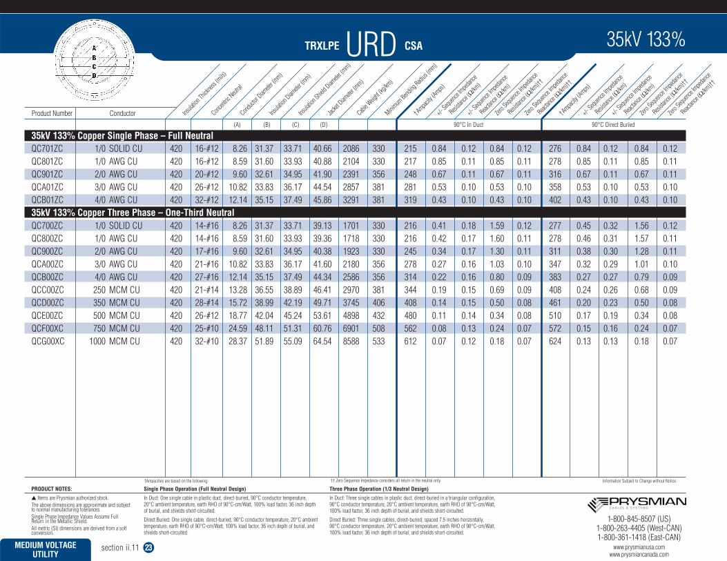
TRXLPE URD CSA
Single Phase Operation (Full Neutral Design)
In Duct: One single cable in plastic duct, direct-buried, 90°C conductor temperature, 20°C ambient temperature, earth RHO of 90°C-cm/Watt, 100% load factor, 36 inch depthof burial, and shields short-circuited.
Direct Buried: One single cable, direct-buried, 90°C conductor temperature, 20°C ambienttemperature, earth RHO of 90°C-cm/Watt, 100% load factor, 36 inch depth of burial, andshields short-circuited.
Three Phase Operation (1/3 Neutral Design)
In Duct: Three single cables in plastic duct, direct-buried in a triangular configuration,90°C conductor temperature, 20°C ambient temperature, earth RHO of 90°C-cm/Watt,100% load factor, 36 inch depth of burial, and shields short-circuited.
Direct Buried: Three single cables, direct-buried, spaced 7.5 inches horizontally, 90°C conductor temperature, 20°C ambient temperature, earth RHO of 90°C-cm/Watt,100% load factor, 36 inch depth of burial, and shields short-circuited.
PRODUCT NOTES:
Items are Prysmian authorized stock.The above dimensions are approximate and subjectto normal manufacturing tolerances.Single Phase Impedance Values Assume Full Return in the Metallic Shield.All metric (SI) dimensions are derived from a softconversion.
†Ampacities are based on the following: Information Subject to Change without Notice.
MEDIUM VOLTAGE UTILITY
section ii.11 23
(A) (B) (C) (D) 90°C In Duct 90°C Direct Buried
QC701ZC 1/0 SOLID CU 420 16-#12 8.26 31.37 33.71 40.66 2086 330 215 0.84 0.12 0.84 0.12 276 0.84 0.12 0.84 0.12QC801ZC 1/0 AWG CU 420 16-#12 8.59 31.60 33.93 40.88 2104 330 217 0.85 0.11 0.85 0.11 278 0.85 0.11 0.85 0.11QC901ZC 2/0 AWG CU 420 20-#12 9.60 32.61 34.95 41.90 2391 356 248 0.67 0.11 0.67 0.11 316 0.67 0.11 0.67 0.11QCA01ZC 3/0 AWG CU 420 26-#12 10.82 33.83 36.17 44.54 2857 381 281 0.53 0.10 0.53 0.10 358 0.53 0.10 0.53 0.10QCB01ZC 4/0 AWG CU 420 32-#12 12.14 35.15 37.49 45.86 3291 381 319 0.43 0.10 0.43 0.10 402 0.43 0.10 0.43 0.10
QC700ZC 1/0 SOLID CU 420 14-#16 8.26 31.37 33.71 39.13 1701 330 216 0.41 0.18 1.59 0.12 277 0.45 0.32 1.56 0.12QC800ZC 1/0 AWG CU 420 14-#16 8.59 31.60 33.93 39.36 1718 330 216 0.42 0.17 1.60 0.11 278 0.46 0.31 1.57 0.11QC900ZC 2/0 AWG CU 420 17-#16 9.60 32.61 34.95 40.38 1923 330 245 0.34 0.17 1.30 0.11 311 0.38 0.30 1.28 0.11QCA00ZC 3/0 AWG CU 420 21-#16 10.82 33.83 36.17 41.60 2180 356 278 0.27 0.16 1.03 0.10 347 0.32 0.29 1.01 0.10QCB00ZC 4/0 AWG CU 420 27-#16 12.14 35.15 37.49 44.34 2586 356 314 0.22 0.16 0.80 0.09 383 0.27 0.27 0.79 0.09QCC00ZC 250 MCM CU 420 21-#14 13.28 36.55 38.89 46.41 2970 381 344 0.19 0.15 0.69 0.09 408 0.24 0.26 0.68 0.09QCD00ZC 350 MCM CU 420 28-#14 15.72 38.99 42.19 49.71 3745 406 408 0.14 0.15 0.50 0.08 461 0.20 0.23 0.50 0.08QCE00ZC 500 MCM CU 420 26-#12 18.77 42.04 45.24 53.61 4898 432 480 0.11 0.14 0.34 0.08 510 0.17 0.19 0.34 0.08QCF00XC 750 MCM CU 420 25-#10 24.59 48.11 51.31 60.76 6901 508 562 0.08 0.13 0.24 0.07 572 0.15 0.16 0.24 0.07QCG00XC 1000 MCM CU 420 32-#10 28.37 51.89 55.09 64.54 8588 533 612 0.07 0.12 0.18 0.07 624 0.13 0.13 0.18 0.07
Insula
tion Th
icknes
s (mils)
Concent
ric Neut
ralCond
uctor
Diamete
r (mm)
Insula
tion Diam
eter (m
m)Ins
ulation
Shield D
iamete
r (mm)
Jacket
Diamete
r (mm)
Cable W
eight (
kg/km
)Minim
um Bend
ing Radi
us (m
m)
†Ampacity
(Amps)+/-
Sequenc
e Imped
ance
Resista
nce (Ω
/km)
+/- Sequ
ence Im
pedanc
e
Reactan
ce (Ω
/km)
Zero S
equenc
e Imped
ance
Resista
nce (Ω
/km)††
Zero S
equenc
e Imped
ance
Reactan
ce (Ω
/km)††
+/- Sequ
ence Im
pedanc
e
Resista
nce (Ω
/km)
+/- Sequ
ence Im
pedanc
e
Reactan
ce (Ω
/km)
Zero S
equenc
e Imped
ance
Resista
nce (Ω
/km)††
Zero S
equenc
e Imped
ance
Reactan
ce (Ω
/km)††
†Ampacity
(Amps)
Product Number Conductor
35kV 133% Copper Single Phase – Full Neutral
35kV 133% Copper Three Phase – One-Third Neutral
1-800-845-8507 (US)1-800-263-4405 (West-CAN)1-800-361-1418 (East-CAN)
www.prysmianusa.comwww.prysmiancanada.com
35kV 133%
†† Zero Sequence Impedance considers all return in the neutral only.