iihs side impact outrigger assembly procedure
TRANSCRIPT
IIHS Side Impact Outrigger
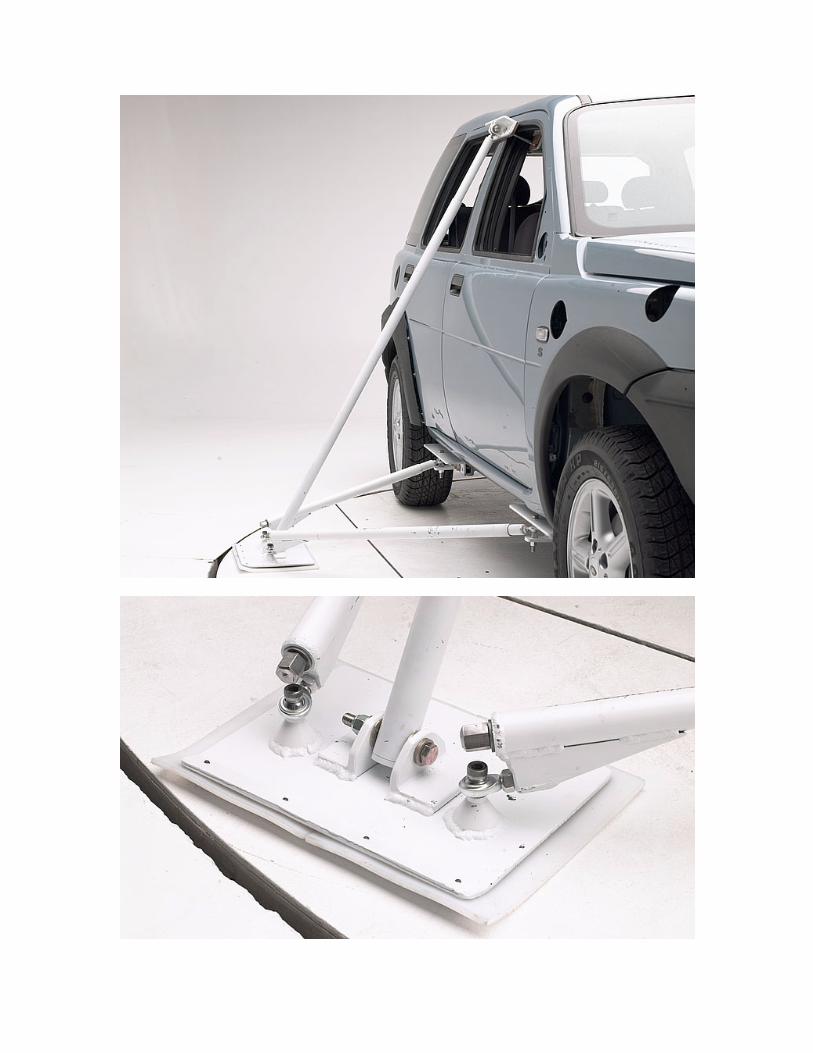
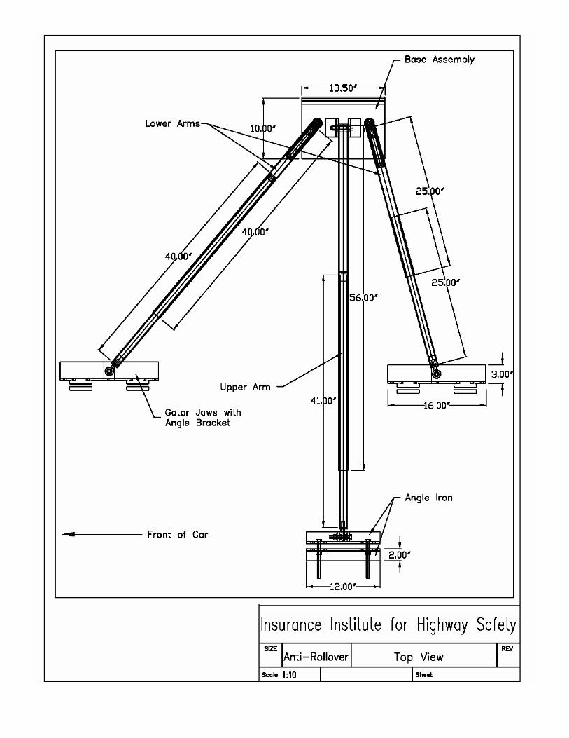
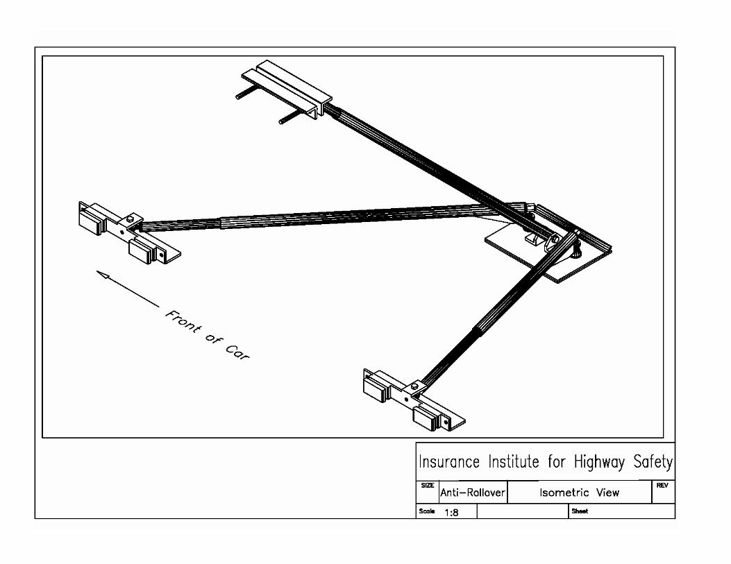
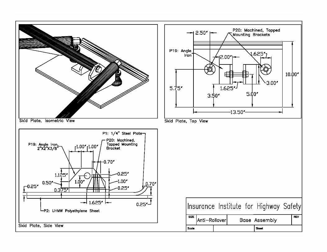
Assembly Procedure Base Assembly (14.3 lbs) The base assembly consists of a ¼” thick steel plate, a ¼” thick piece of polyethylene, and mounting fixtures for the upper and lower arms. The plate (P1) measures 10” x 13.5,” with the long edges running parallel to the vehicle. The edge facing away from the vehicle was bent upward slightly. The UHMW polyethylene (P2) is attached to the bottom of the plate with screws recessed into this upturned edge. The two mounting brackets for the lower arms (P20) were machined from a 1-5/8” diameter bar of mild steel. They were then tapped at ½”-13, for the allen cap screws (P14). These brackets were welded to P1 around their edges. The two mounting brackets for the upper arm were cut from 2” x 2” x 3/8” angle iron (P19). ½” holes were drilled through the upper portions for a bolt to secure them to the lower arm. These brackets were welded to P1 around their edges. Upper Arm (27.0 lbs) The upper arm consists mainly of outer (P3) and inner (P4) poles of chromemoly tubing, two die springs (P7 and P8), two pieces of angle iron (P19) for securing the assembly to the B-pillar of the vehicle, and fixtures for mounting the arm to the base and the angle iron.
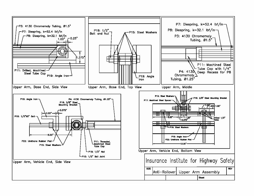
The outer pole (P3) is 4130 chromemoly tubing with an outside diameter of 1½” and a length of 56”. A tube cap (P11) has been machined out of mild steel to fit inside the lower end of the pole. This cap was welded to the pole, and a hole was drilled through both to accommodate a ½” bolt securing the pole to the mounting brackets on the base assembly. Four steel washers were used as well, one on each side of both brackets.
Two die springs were placed inside the outer tube to decreases the rate of impact on the plate and floor. The outer spring (P7) has a spring constant of 52.4 lbf/in, and is 20” long. The second spring (P8) was placed inside the first, has a spring constant of 32.1 lbf/in, and is 23” long. The extra length of the inner spring allows for a preload to be placed on the upper arm when securing the assembly to the vehicle. Both springs sit on the tube cap (P11) at the lower end of the outer pole.
The inner pole (P4) is 4130 chromemoly tubing with an outside diameter of 1¼” and a length of 41”. A tube cap (P11) has been machined out of mild steel to fit inside the lower end of the pole. This cap was welded to the pole, and a round groove, ¼” deep and ¾” in diameter, was machined into the outside of the cap in order to seat the inner spring (P8) for stability during loading.
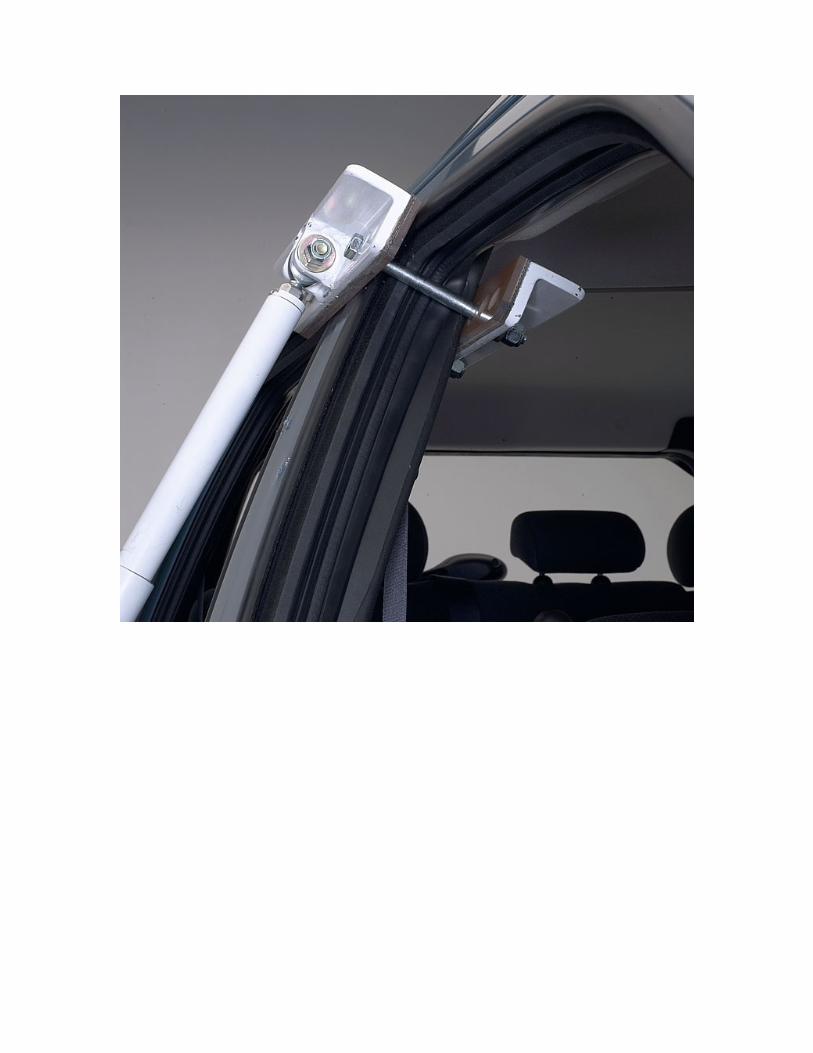
At the vehicle end of the inner pole (P4), a tube cap (P11) was machined and tapped to accommodate a ½” ball joint (P10). This cap has been welded to the pole and a ½” nut is used for making adjustments when securing the assembly to the vehicle. Two pieces of 2” x 2” x 3/8” angle iron (P19) are used to grip the B-pillar of the vehicle. Each was cut 12” long and drilled with three ½” holes near each end to allow a good fit on B-pillars of different widths. Two steel brackets (P16) were cut from 3/8” mild steel, drilled with ½” holes, and welded to the inside of one of the pieces of angle iron. The ball joint (P10) from the upper arm is fixed between these two brackets with a bolt. Two
spacers (P17) were machined from mild steel to secure the ball joint in the middle of the two brackets, allowing it a greater range of motion.
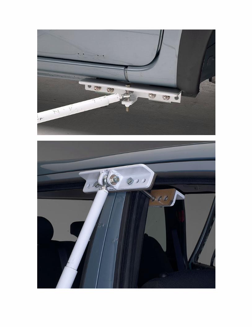
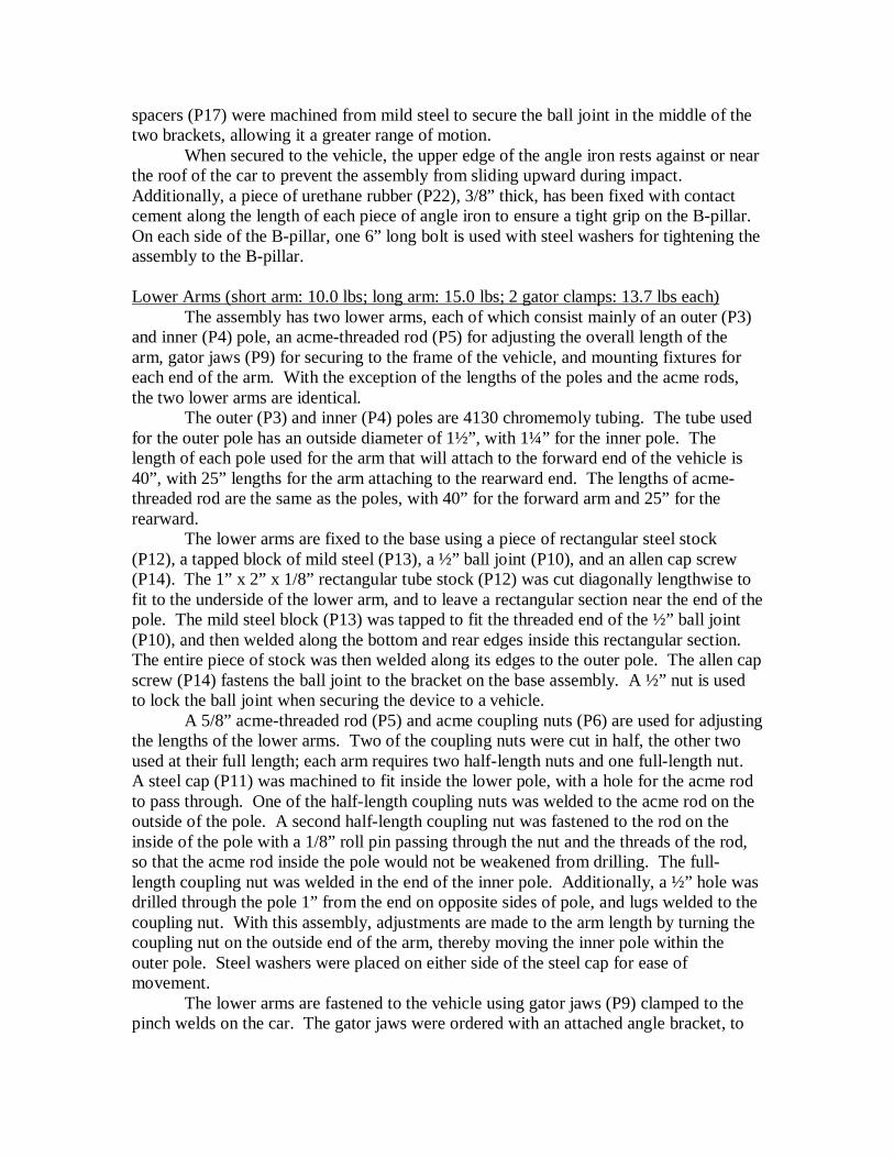
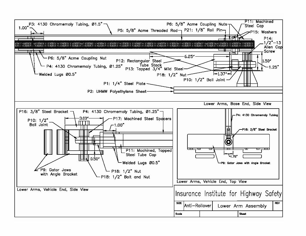
When secured to the vehicle, the upper edge of the angle iron rests against or near the roof of the car to prevent the assembly from sliding upward during impact. Additionally, a piece of urethane rubber (P22), 3/8” thick, has been fixed with contact cement along the length of each piece of angle iron to ensure a tight grip on the B-pillar. On each side of the B-pillar, one 6” long bolt is used with steel washers for tightening the assembly to the B-pillar. Lower Arms (short arm: 10.0 lbs; long arm: 15.0 lbs; 2 gator clamps: 13.7 lbs each) The assembly has two lower arms, each of which consist mainly of an outer (P3) and inner (P4) pole, an acme-threaded rod (P5) for adjusting the overall length of the arm, gator jaws (P9) for securing to the frame of the vehicle, and mounting fixtures for each end of the arm. With the exception of the lengths of the poles and the acme rods, the two lower arms are identical. The outer (P3) and inner (P4) poles are 4130 chromemoly tubing. The tube used for the outer pole has an outside diameter of 1½”, with 1¼” for the inner pole. The length of each pole used for the arm that will attach to the forward end of the vehicle is 40”, with 25” lengths for the arm attaching to the rearward end. The lengths of acme-threaded rod are the same as the poles, with 40” for the forward arm and 25” for the rearward. The lower arms are fixed to the base using a piece of rectangular steel stock (P12), a tapped block of mild steel (P13), a ½” ball joint (P10), and an allen cap screw (P14). The 1” x 2” x 1/8” rectangular tube stock (P12) was cut diagonally lengthwise to fit to the underside of the lower arm, and to leave a rectangular section near the end of the pole. The mild steel block (P13) was tapped to fit the threaded end of the ½” ball joint (P10), and then welded along the bottom and rear edges inside this rectangular section. The entire piece of stock was then welded along its edges to the outer pole. The allen cap screw (P14) fastens the ball joint to the bracket on the base assembly. A ½” nut is used to lock the ball joint when securing the device to a vehicle. A 5/8” acme-threaded rod (P5) and acme coupling nuts (P6) are used for adjusting the lengths of the lower arms. Two of the coupling nuts were cut in half, the other two used at their full length; each arm requires two half-length nuts and one full-length nut. A steel cap (P11) was machined to fit inside the lower pole, with a hole for the acme rod to pass through. One of the half-length coupling nuts was welded to the acme rod on the outside of the pole. A second half-length coupling nut was fastened to the rod on the inside of the pole with a 1/8” roll pin passing through the nut and the threads of the rod, so that the acme rod inside the pole would not be weakened from drilling. The full-length coupling nut was welded in the end of the inner pole. Additionally, a ½” hole was drilled through the pole 1” from the end on opposite sides of pole, and lugs welded to the coupling nut. With this assembly, adjustments are made to the arm length by turning the coupling nut on the outside end of the arm, thereby moving the inner pole within the outer pole. Steel washers were placed on either side of the steel cap for ease of movement. The lower arms are fastened to the vehicle using gator jaws (P9) clamped to the pinch welds on the car. The gator jaws were ordered with an attached angle bracket, to
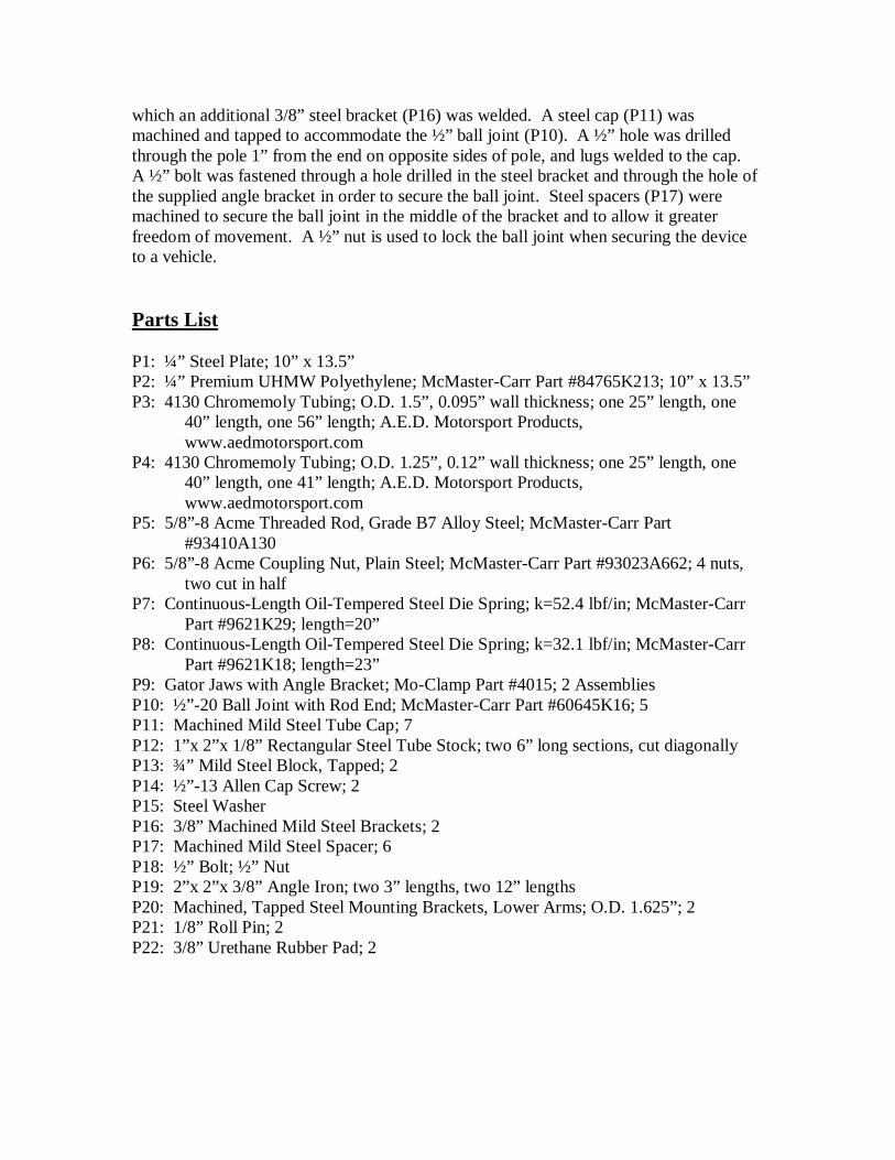
which an additional 3/8” steel bracket (P16) was welded. A steel cap (P11) was machined and tapped to accommodate the ½” ball joint (P10). A ½” hole was drilled through the pole 1” from the end on opposite sides of pole, and lugs welded to the cap. A ½” bolt was fastened through a hole drilled in the steel bracket and through the hole of the supplied angle bracket in order to secure the ball joint. Steel spacers (P17) were machined to secure the ball joint in the middle of the bracket and to allow it greater freedom of movement. A ½” nut is used to lock the ball joint when securing the device to a vehicle. Parts List P1: ¼” Steel Plate; 10” x 13.5” P2: ¼” Premium UHMW Polyethylene; McMaster-Carr Part #84765K213; 10” x 13.5” P3: 4130 Chromemoly Tubing; O.D. 1.5”, 0.095” wall thickness; one 25” length, one
40” length, one 56” length; A.E.D. Motorsport Products, www.aedmotorsport.com
P4: 4130 Chromemoly Tubing; O.D. 1.25”, 0.12” wall thickness; one 25” length, one 40” length, one 41” length; A.E.D. Motorsport Products, www.aedmotorsport.com
P5: 5/8”-8 Acme Threaded Rod, Grade B7 Alloy Steel; McMaster-Carr Part #93410A130
P6: 5/8”-8 Acme Coupling Nut, Plain Steel; McMaster-Carr Part #93023A662; 4 nuts, two cut in half
P7: Continuous-Length Oil-Tempered Steel Die Spring; k=52.4 lbf/in; McMaster-Carr Part #9621K29; length=20”
P8: Continuous-Length Oil-Tempered Steel Die Spring; k=32.1 lbf/in; McMaster-Carr Part #9621K18; length=23”
P9: Gator Jaws with Angle Bracket; Mo-Clamp Part #4015; 2 Assemblies P10: ½”-20 Ball Joint with Rod End; McMaster-Carr Part #60645K16; 5 P11: Machined Mild Steel Tube Cap; 7 P12: 1”x 2”x 1/8” Rectangular Steel Tube Stock; two 6” long sections, cut diagonally P13: ¾” Mild Steel Block, Tapped; 2 P14: ½”-13 Allen Cap Screw; 2 P15: Steel Washer P16: 3/8” Machined Mild Steel Brackets; 2 P17: Machined Mild Steel Spacer; 6 P18: ½” Bolt; ½” Nut P19: 2”x 2”x 3/8” Angle Iron; two 3” lengths, two 12” lengths P20: Machined, Tapped Steel Mounting Brackets, Lower Arms; O.D. 1.625”; 2 P21: 1/8” Roll Pin; 2 P22: 3/8” Urethane Rubber Pad; 2
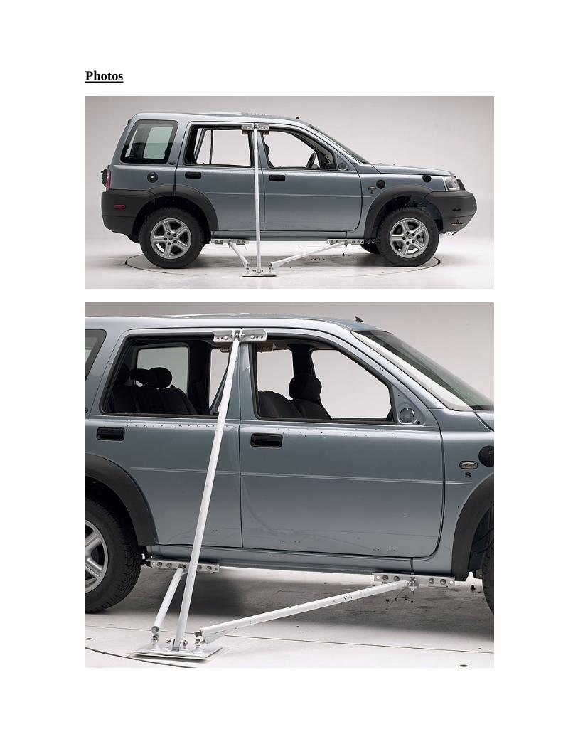
Photos