iii. attitude hold autopilots. - cvut.cz · iii. attitude hold autopilots. ... alpha is...
TRANSCRIPT
III. Attitude hold autopilots.
Stabilization of aircraft pitch, roll and yaw angles. Multiloop SISO design approach. Proporional and integrating control laws.
Control
& aerospace applications

Stabilization of attitude angles: attitude hold autopilots
-
attitude-hold autopilots (stabilizers / reference trackers of pitch, roll
and yaw angles) are essential first-level automatic control (i.e. “lost pilot’s authority”
–
-
compare with dampers) loops of any FCS -
basic functionality of autopilots for piloted aircraft (for almost a century ☺)
as well as control systems for UAV’s
-
if the attitude-hold circuits (codes) work properly, all subsequent loops (VOR / GPS navigation, ILS, altitude select, vertical speed, ...) are easy to design
-
careful design of the autopilots is therefore essential (transients, rise times, robustness w.r.t. parameter changes and flight envelope variables, ...)
-
design approaches: nested SISO loops (with pre-designed separate dampers), or MIMO design (with integrated dampers functionality –
LQ control to be
discussed later, H2/Hinf synthesis etc.)

Stabilization of attitude angles: attitude hold autopilots
Pitch autopilot: signal diagram
A/C LONG
v
alpha
theta
q
K_damp
delta_TH
delta_EL fligh
t va
riabl
es
flight model
–K_AP–
pitch angle reference (by pilot
or higher-level controls – - vertical speed, altitude select, ...
K_alpha_limiter
Dead Zone
–
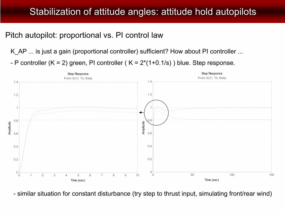
K_AP ... is just a gain (proportional controller) sufficient? How about PI controller ...
Stabilization of attitude angles: attitude hold autopilots
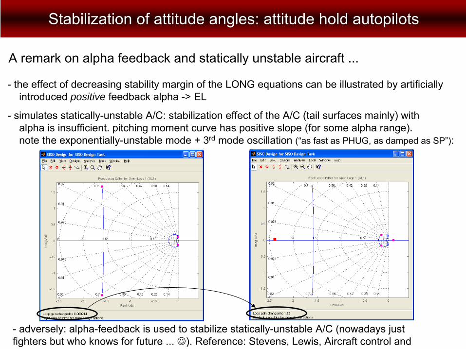
A remark on alpha feedback and statically unstable aircraft ...
-
the effect of decreasing stability margin of the LONG equations
can be illustrated by artificially introduced positive feedback alpha -> EL
-
simulates statically-unstable A/C: stabilization effect of the A/C (tail surfaces mainly) with alpha is insufficient. pitching moment curve has positive slope (for some alpha range). note the exponentially-unstable mode + 3rd
mode oscillation (“as fast as PHUG, as damped as SP”):
-
adversely: alpha-feedback is used to stabilize statically-unstable A/C (nowadays just fighters but who knows for future ... ☺). Reference: Stevens, Lewis, Aircraft control and
Stabilization of attitude angles: attitude hold autopilots
K_AP ... is just a gain (proportional controller) sufficient? How about PI controller ...
-
P controller (K = 2) green, PI controller ( K = 2*(1+0.1/s) ) blue. Step response.
0 1 2 3 4 5 6 7 8 9 100
0.2
0.4
0.6
0.8
1
1.2
1.4From: In(1) To: theta
Step Response
Time (sec)
Ampl
itude
0 50 100 1500
0.2
0.4
0.6
0.8
1
1.2
1.4From: In(1) To: theta
Step Response
Time (sec)
Ampl
itude
-
similar situation for constant disturbance (try step to thrust input, simulating front/rear wind)
Pitch autopilot: proportional vs. PI control law

Stabilization of attitude angles: attitude hold autopilots
-
P controller (K = 2) green, PI controller ( K = 2*(1+0.1/s) ) blue. Step response
in thrust.
-
similar situation for constant disturbance (try step to thrust input, simulating front/rear wind)
0 20 40 60 80 100 120 140 160 1800
0.05
0.1
0.15
0.2
0.25
0.3
0.35From: In(1) To: theta
Step Response
Time (sec)
Ampl
itude
Pitch autopilot: proportional vs. PI control law

Stabilization of attitude angles: attitude hold autopilots
-
pre-designed
pitch damper pre-determines, to considerble extent, achievable performance of the pitch-angle stabilizer (pitch autopilot) –
overshoot, settling time, gain/phase margins, ...
-
tedious re-designs of already computed controllers (pitch damper, in this case) are often required, during this loop-by-loop procedure, in order to achieve acceptable performance
-
K_damp = 0.5
K_damp = 1 (... well, best results I got ☺, for comparable maximum EL deflection and gain / phase margins)
-
this trouble can be avoided / reduced if advanced MIMO design procedures are used (e.g. LQ control)
Pitch autopilot: interaction with pitch damper
Stabilization of attitude angles: attitude hold autopilots
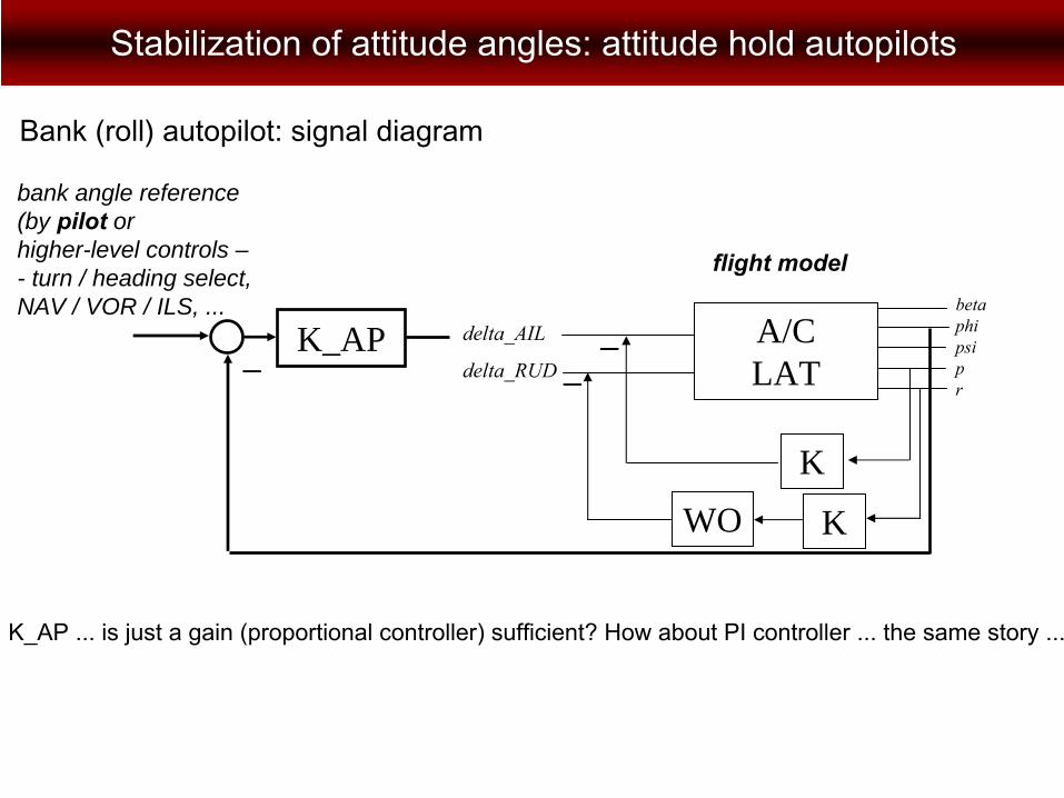
Bank (roll) autopilot: signal diagram
K_AP–
bank angle reference (by pilot
or higher-level controls – - turn / heading select, NAV / VOR / ILS, ...
K_AP ... is just a gain (proportional controller) sufficient? How about PI controller ... the same story ...
A/C LAT
K
delta_AIL
delta_RUD
flight model
–
beta
phi
psi
p
r
KWO
–
Stabilization of attitude angles: attitude hold autopilots
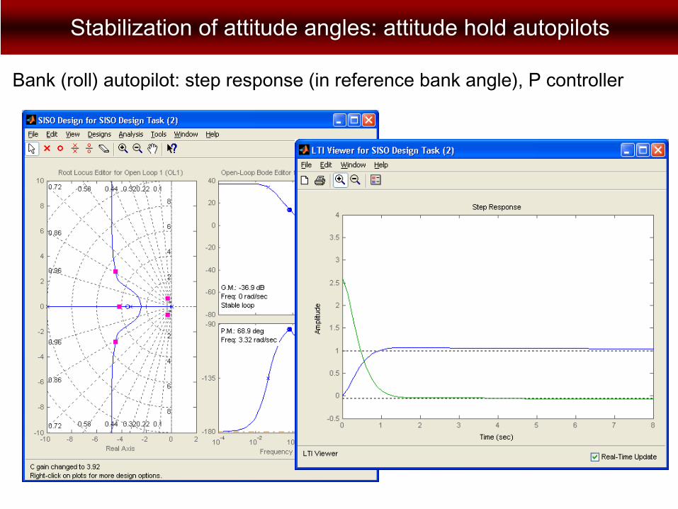
Bank (roll) autopilot: step response (in reference bank angle), P controller
Stabilization of attitude angles: attitude hold autopilots
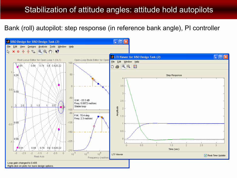
Bank (roll) autopilot: step response (in reference bank angle), PI controller
Saturation
Stabilization of attitude angles: attitude hold autopilots
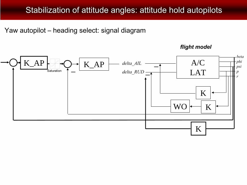
Yaw autopilot –
heading select: signal diagram
K_AP–
A/C LAT
K
delta_AIL
delta_RUD
flight model
–
beta
phi
psi
p
r
KWO
–K_AP
K

Stabilization of attitude angles: attitude hold autopilots
Yaw autopilot –
heading select
- two loops added on top of bank autopilot for coordinated (correct) turn
-
yaw-angle (heading) loop, giving setpoint for bank autopilot (mind the artificially added saturation to avoid excessive bank angles
for large yaw angle setpoint changes
-
beta stabilization –
for turn coordination (beta should be zero, assuring zero on-board side acceleration)
- roll angle and yaw rate are given for coordinated turn by the equation
(independent of A/C physical parameters competely ...)
-
the beta stabilizer has also other purposes –
landing at side-wind, OEI (one engine inoperative) flight, ...

Stabilization of attitude angles: attitude hold autopilots
Yaw autopilot: step response (in reference bank angle), PI controller
0 5 10 15 20 25 30 35 40 45 50-200
-150
-100
-50
0
50
time (s)
angl
e ( °
)
Stabilizace kurzu
φψβ
-
yaw-angle (heading) loop, giving setpoint for bank autopilot
-
artificially added saturation to avoid excessive bank angles for large yaw angle setpoint changes
- beta stabilization
-
P or PI ontrol? A bit tricky. -
REF vs. DIST ...
-
mind ainti-windup ...