iii fatigue models - illinois
TRANSCRIPT

III Fatigue Models
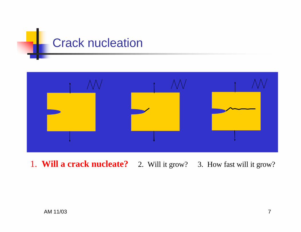
1. Will a crack nucleate? 2. Will it grow? 3. How fast will it grow?

AM 11/03 2
Outline
nnSources of knowledgeSources of knowledgenn ModelingModelingnn Crack nucleationCrack nucleationnn Non propagating cracksNon propagating cracksnn Crack growth Crack growth

AM 11/03 3
The intrinsic fatigue properties of the component’s material are determined using small, smooth or cracked specimens.
Source of knowledge

AM 11/03 4This information can be used to predict, to compute the answer to…….
Smooth specimens
Crack growth specimen
Laboratory fatigue test specimens

AM 11/03 5
Outline
nn Sources of knowledgeSources of knowledge
nn ModelingModelingnnCrack nucleationCrack nucleationnn Non propagating cracksNon propagating cracksnn Crack growthCrack growth

AM 11/03 6
1. Will a crack nucleate? 2. Will it grow? 3. How fast will it grow?
The three BIG fatigue questions
AM 11/03 7
1. Will a crack nucleate? 2. Will it grow? 3. How fast will it grow?
Crack nucleation

AM 11/03 8
Cyclic behavior of materials
Bauschinger effect: monotonic and cyclic stress-strain different!
monotonic
cyclic
? ε

AM 11/03 9
Cyclic Deformation
Hysteresis loops? ε

AM 11/03 10
MODEL: Cyclic stress-strain curve
ε
σ Cyclic stress-strain curve
Hysteresis loops for different levels of applied strain
? ε
ε = σE
+ σK '
1/n '
∆ε = ∆σE
+2 ∆σ2K '
1/n '

AM 11/03 11
MODEL: Cyclic stress-strain curve
ε = σE
+ σK '
1/n '
ε = σE
+ σK
1/n

AM 11/03 12
MODEL USES
n Simulate local cyclic stress-strain behavior at a notch root.
n May need to include cyclic hardening and softening behavior and mean stress relaxation effects.
Kt
S(t)
Notched component
σ, ε

AM 11/03 13
Planar and wavy slip materials
Wavy slip materials Planar slip materials

AM 11/03 14
Concept of fatigue damage
Plastic strains cause the accumulation of “fatigue damage.”
1954 - Coffin and Manson

AM 11/03 15
106
105
104
103
.0001
.001
.01
.1
total strain ampltudeelastic strain ampltudeplastic strain ampltude
Reversals (2Nf)
σ'f b
c
ε' f
E
²e
∆ε t = ∆ε e + ∆εp =σ' fE
2Nf( )b + ε' f 2Nf( )c
MODEL: Strain-life curve
Fatigue test data from strain-controlled tests on smooth specimens.
Elastic component of strain, ? εe
Plastic component of strain, ? εp

AM 11/03 16
Transition Fatigue Life
106
105
104
103
.0001
.001
.01
.1
total strain ampltudeelastic strain ampltudeplastic strain ampltude
Reversals (2Nf)
σ'f b
c
ε' f
E
²e
Transition fatigue life, NtrElastic strains = plastic strains
2Ntr =ε f
' E
σ f'
1b−c

AM 11/03 17
10 710 610 510 41
10
100
Fatigue Life ( N, cycles)
Endurance Limit
2,000,000 cycles
N
ni
i
niN i
≥ 1i
∑ .0
Miner's Rule of Cumulative Fatigue Damage is the best and simplest tool available to estimate the likelihood of fatigue failure under variable load histories. Miner's rule hypothesizes that fatigue failure will occur when the sum of the cycle ratios (ni/Ni) is equal to or greater than 1
ni = Number of cycles experienced at a given stress or load level.Ni = Expected fatigue life at that stress or load level.
MODEL: Linear cumulative damage

AM 11/03 18
Mean stress effects
log 2Nf
log
?ε/
2
Compressive mean stressZero mean stressTensile mean stress
Good!
Bad!
Effects the growth of (small) fatigue cracks.

AM 11/03 19
MODEL: Morrow’s mean stress correction
log 2Nf
log
?ε/
2
Zero mean stress
Tensile mean stress
σf’/E
σm/E
∆ε2
=σ f
' − σ m
E2N f( )b
+ε f' 2N f( )c

AM 11/03 20
0.0001
0.001
0.01
0.1
1E+02 1E+03 1E+04 1E+05 1E+06
Cycles
Morrow -200 MPa
SWT -200 MPa
Morrow +200 MPa
SWT +200MPa
σmax∆ε2
=σ f
' 2
E2N f( )2b
+σ f' ε f
' 2N f( )b +c
MODEL: Mean stress effects
∆ε2
=σ f
' − σ m
E2N f( )b
+ε f' 2N f( )cMorrow
Smith-Watson-Topper

AM 11/03 21
A strain gage mounted in a high stress region of a component indicates a cyclic strain of 0.002. The number of reversals to nucleate a crack (2NI) is estimated to be 86,000 or 43,000 cycles.
∆ε t = ∆ε e + ∆εp =σ' fE
2Nf( )b + ε' f 2Nf( )c
106
105
104
103
.0001
.001
.01
.1
total strain ampltudeelastic strain ampltudeplastic strain ampltude
Reversals (2Nf)
σ'f b
c
ε' f
0.002
86,000 reversals
E
²e
MODEL USES

AM 11/03 22
Outline
nn Sources of knowledgeSources of knowledgenn ModellingModellingnn Crack nucleationCrack nucleation
nnNon propagating cracksNon propagating cracksnn Crack growthCrack growth

AM 11/03 23
1. Will a crack nucleate? 2. Will it grow? 3. How fast will it grow?
The three BIG fatigue questions

AM 11/03 24
Sharp notches may nucleate cracks but the remote stress may not be large enough to allow the crack to leave the notch stress field.
Non-propagating cracks

AM 11/03 25
Threshold Stress Intensity
? S
a
∆K = Y ∆S πa
The forces driving a crack forward are related to the stress intensity factor
At or below the threshold value of ? K, the crack doesn’t grow.

AM 11/03 26
MODEL: Non-propagating cracks
Crack length
Endurance limit for smooth specimens
Stre
ss ra
nge,
?S
Non-propagatingcracks
Failureath =
1π
∆Kth∆S
2

AM 11/03 27
? S
? K ? K
? P = ? S W
Groove Welded Butt Joint
Tensile-Shear Spot Weld
W? P
∆K =Y2
∆P / Bπa
+ ∆S πa
∆K = ∆S πa
a a
initial crack length
W˜ 8
P2Cycles, N P2Cycles, N

AM 11/03 28
MODEL USES
a
n Will the defect of length a grow under the applied stress range ?S?
n How sensitive should our NDT techniques be to ensure safety?
? S
ath =1π
∆Kth∆S
2

AM 11/03 29
Outline
nn Fatigue mechanismsFatigue mechanismsnn Sources of knowledgeSources of knowledgenn ModellingModellingnn Crack nucleationCrack nucleationnn Non propagating cracksNon propagating cracks
nnCrack growthCrack growth

AM 11/03 30
1. Will a crack nucleate? 2. Will it grow? 3. How fast will it grow?
The three BIG fatigue questions

AM 11/03 31
Measuring Crack Growth - Everything we know about crack growth begins here!
Cracks grow faster as their length increases.
How fast will it grow???

AM 11/03 32
Growth of fatigue cracks is correlated with the range in stress intensity factor: ? K.
MODEL: Paris Power Law
dadN
= C ∆K( )n
∆K = Y ∆S πa

AM 11/03 33
Fatigue fracture surface
Scanning electronmicroscope image -striations clearly visible
Schematic drawing ofa fatigue fracturesurface

AM 11/03 34
Crack growth rate (da/dN) is related to the crack tip stress field and is thus strongly correlated with the range of stress intensity factor: (? K=Y? Svpa).
dadN
= C ∆K( )n
Paris power law
MODEL: Crack growth rate versus ?K

AM 11/03 35
Crack Growth Data
All ferritic-pearlitic, that is, plain carbon steels behave about the same irrespective of strength or grain size!

AM 11/03 36
The fatigue crack growth rates for Al and Ti are much more rapid than steel for a given ? K. However, when normalized by Young’s Modulus all metals exhibit about the same behavior.
Crack growth rates of metals∆KE

AM 11/03 37
Forman’s equation which includes the effects of mean stress.
Walker’s equation which includes the effect of mean stress.
MODEL: Mean stresses (R ratio)
dadN
= C ∆K m
1− R( )Kc − ∆K
dadN
= C ∆K m
1− R( ) γ

AM 11/03 38
While some applications are actually constant amplitude, many or most applications involve variable amplitude loads (VAL) or variable load histories (VLH).
Aircraft load histories
PROBLEM: Variable load histories?

AM 11/03 39
FIX: Root mean cube method
∆K =∆Ki( )mni∑
ni∑m

AM 11/03 40
Overloads retard crack growth, under-loads accelerate crack growth.
PROBLEM: Overloads, under-loads?

AM 11/03 41
Infrequent overloads help, but more frequent may be even better. Too frequent overloads very damaging.
Effects of Periodic Overloads
PROBLEM: Periodic overloads?
AM 11/03 42
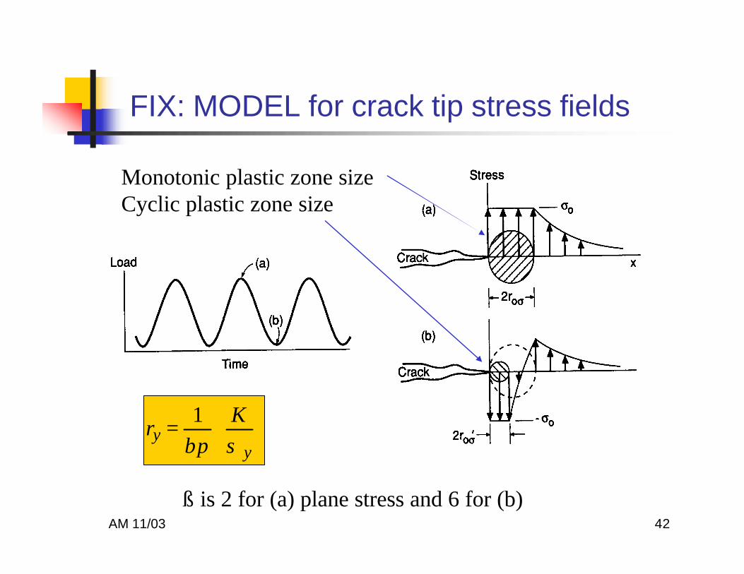
FIX: MODEL for crack tip stress fields
ry = 1βπ
Kσ y
ß is 2 for (a) plane stress and 6 for (b)
Monotonic plastic zone sizeCyclic plastic zone size

AM 11/03 43
MODEL: Overload plastic zone size
Crack growth retardation ceases when the plastic zone of ith cycle reaches the boundary of the prior overload plastic zone.
ß is 2 for plane stress and 6 for plain strain.
ry = 1βπ
Kσ y

AM 11/03 44
MODEL: Retarded crack growth
dadN
VA
= βdadN
CA
β =2 ry
a p − a i
k
ry =1
2 πK
σ ys
2
Wheeler model

AM 11/03 45
Infrequent overloads help, but more frequent may be even better. Too frequent overloads very damaging.
Effects of Periodic Overloads
Retarded crack growth

AM 11/03 46
Infrequent overloads help, but more frequent may be even better. Too frequent overloads very damaging.
Effects of Periodic Overloads
PROBLEM: Periodic overloads?

AM 11/03 47
Sequence Effects
Last one controls!
Compressive overloads accelerate cdrack growth by reducing roughness of fracture surfaces.
Compressive followed by tensile overloads…retardation!
Tensile followed by compressive, little retardation

AM 11/03 48
Overloads retard crack growth, under-loads accelerate crack growth.
Sequence effects

AM 11/03 49
PROBLEMS: Small Crack Growth?
Small cracks don’t behave like long cracks! Why?

AM 11/03 50
A. Dissolution of crack tip.
B. Dissolution plus H+ acceleration.
C. H+ acceleration
D. Corrosion products may retard crack growth at low ? K.
B
C D
A
PROBLEMS: Environment?

AM 11/03 51
FIX: Crack closure
Plastic wake New plastic deformation
S = Smax
S = 0
S
S
Rem
ote
Stre
ss, S
Time, t
Smax
Sopen, Sclose
Rem
ote
Stre
ss, S
Time, t
Smax
Sopen, Sclose
Crack open
Crack closed

AM 11/03 52
CAUSE: Plastic Wake
Short cracks can’t do this so they behave differently!

AM 11/03 53
“Effective” part of load history
Damaging portion of loading history
Nondamaging portion of loading history
Opening load
S
S
S
S

AM 11/03 54
MODEL: Crack closure
dadn
= C ∆K( )m K max( )p ExtrinsicIntrinsic

AM 11/03 55
Other sources of crack closure
SopenSmax
(b)
Smax Sopen
(a)
Roughness inducedcrack closure (RICC)
Oxide inducedcrack closure (OICC)

AM 11/03 56
MODEL: Crack closure
U =∆Keff
∆K=
Smax −Sopen
Smax −Smin=
11− R
1−Sopen
Smax
Initial crack length
A''A A'
A, A', A'' Crack tip positions
Plastic zones for crack positions A...A”
Plastic wake
? Keff = U ? K
Plasticity induced crack closure (PICC)
U ≈ 0.5 + 0.4R (sometimes)

AM 11/03 57
The use of the effective stress intensity factor accounts for the effects of mean stress.
dadN
= C ∆K( )n
dadN
= C' ∆Keff( )n= C' U∆K( )n
MODEL USE: ?Keffective