i.i.s.s. “giancardi-galilei-aicardi” alassio istituto ... · del comparatore analogico...
TRANSCRIPT
I.I.S.S. “Giancardi-Galilei-Aicardi” Alassio-Albenga
Istituto Tecnico Industriale Statale “G.Galilei” Albenga
Elettronica e Telecomunicazioni
Anno scolastico 2008-2009
Classe Va sez. B

CLASSE Va SEZ. B
1. Cacciò Chiara
2. Ghisalberti Davide
3. Loggia Salvatore
4. Marro Matteo
5. Martinelli Andrea
6. Mel Riccardo
7. Mignone Mirko
8. Mirone Mirco
9. Nan Stefano
10. Novena Massimiliano
11. Oberto Daniele
12. Ratto Fabiano
13. Ravaschino Mattia
14. Richero Emanuele
15. Romagnoli Luca
Docente teorico: Prof. Emanuela Ghirardi Docente tecnico-pratico: Prof. Fernando Bianco Assistente tecnico: P.E. Angelo Curcio Docente lingua inglese: Prof. Angiolina Lodrini
Anno Scolastico 2008/2009
I
Indice
Capitolo 1. Il Nutchip
1.1 Presupposti teorici: gli automi a stati finiti Pag. 1
1.2 1.2.1 1.2.2 1.2.3 1.2.4
Caratteristiche tecniche Schema a blocchi Pinout Caratteristiche funzionali Caratteristiche elettriche
Pag. 5 Pag. 5 Pag. 6 Pag. 7 Pag. 7
1.3 La tavola di verità Pag. 8 1.4 Il telecomando Pag. 10 1.5 La programmazione Pag. 11
Capitolo 2. Il cancello automatico
Testo inglese – English translation Capitolo 1. Il Nutchip – Chapter 1. The Nutchip Pag. 24 Capitolo 2. Il cancello automatico - Chapter 2. The automatic gate Pag. 31
Bibliografia
De Santis, Cacciaglia, Saggese Corso di sistemi vol. 1 CALDERINI edagricole
Cuniberti, De Lucchi, Galluzzo TDP Tecnologia Disegno Progettazione Vol.3 Edizioni Petrini Scienze e Tecnologie
www. nutchip.com
2.1 Specifiche di progetto Pag. 13 2.2 Analisi del progetto Pag. 13 2.3 Interfaccia di programmazione Pag. 17 2.4 Interfaccia lampada Pag. 18 2.5 Interfaccia avvisatore acustico Pag. 19 2.6 Interfaccia motore Pag. 20 2.7 2.7.1 2.7.2
Interfaccia fotocellula Circuito emettitore Circuito ricevitore
Pag. 21 Pag. 22 Pag. 23
II
Capitolo 1. Il Nutchip 1.1 Presupposti teorici: gli automi a stati finiti Nello studio dei sistemi è necessario individuare le grandezze, suscettibili di modifiche, definite variabili del sistema. Tali variabili si distinguono in:
Variabili di ingresso , sollecitazioni che possono essere variate direttamente dall‟intervento dell‟uomo;
Variabili d‟uscita, le azioni che il sistema esercita sull‟ambiente;
Variabili di stato o interne, sono le grandezze che descrivono l‟evoluzione del sistema, contengono informazioni sulla sua storia passata e determinano gli stati futuri;
Variabili di disturbo; sollecitazioni non manipolabili. Se un sistema sequenziale, ovvero con memoria, ha un insieme finito di stati interni, di variabili di ingresso e di variabili d‟uscita, se è possibile identificare in esso uno stato iniziale e uno stato finale, esso viene definito macchina sequenziale a stati finiti o automa a (numero di) stati finiti (FSA- Finite State Automaton). Più precisamente definiamo automa a stati finiti un sistema dinamico, discreto ed invariante, in cui gli insiemi d‟ingresso, di uscita e di stato sono in numero finito. La sintesi dei circuiti logici sequenziali, realizzata per mezzo degli automi, diviene, non appena ci si discosta da semplici modelli, complessa e, per questo, ha perso efficacia con l‟introduzione dei sistemi a logica programmabile nei quali le funzioni che un sistema deve
svolgere sono realizzate per mezzo di un programma che controlla un P, un PLC o,
meglio, un controllore.
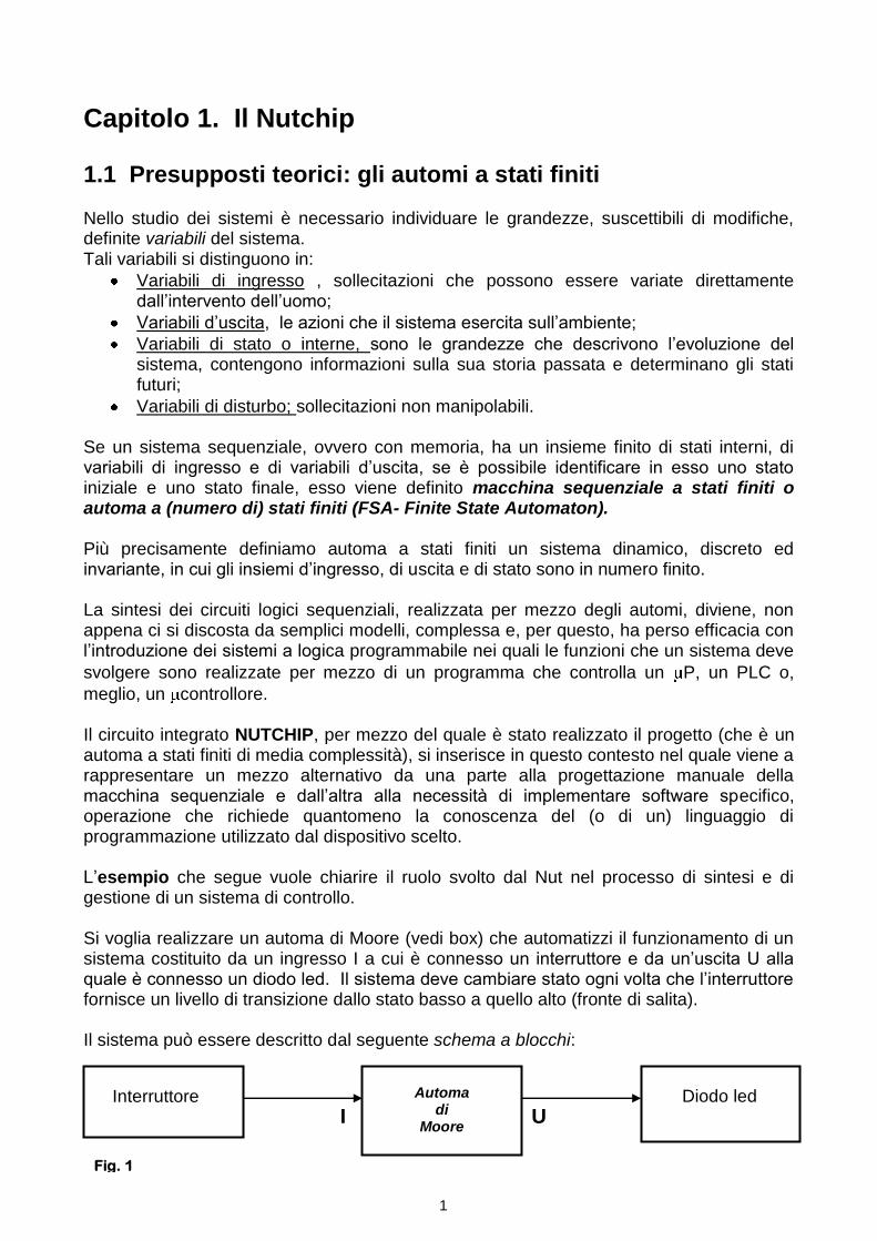
Il circuito integrato NUTCHIP, per mezzo del quale è stato realizzato il progetto (che è un automa a stati finiti di media complessità), si inserisce in questo contesto nel quale viene a rappresentare un mezzo alternativo da una parte alla progettazione manuale della macchina sequenziale e dall‟altra alla necessità di implementare software specifico, operazione che richiede quantomeno la conoscenza del (o di un) linguaggio di programmazione utilizzato dal dispositivo scelto. L‟esempio che segue vuole chiarire il ruolo svolto dal Nut nel processo di sintesi e di gestione di un sistema di controllo. Si voglia realizzare un automa di Moore (vedi box) che automatizzi il funzionamento di un sistema costituito da un ingresso I a cui è connesso un interruttore e da un‟uscita U alla quale è connesso un diodo led. Il sistema deve cambiare stato ogni volta che l‟interruttore fornisce un livello di transizione dallo stato basso a quello alto (fronte di salita). Il sistema può essere descritto dal seguente schema a blocchi:
I U
Automa di
Moore
Interruttore Diodo led
Fig. 1
1
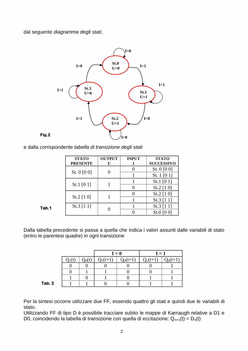
dal seguente diagramma degli stati,
e dalla corrispondente tabella di transizione degli stati
STATO
PRESENTE
OUTPUT
U
INPUT
I
STATO
SUCCESSIVO
St. 0 [0 0] 0 0 St. 0 [0 0]
1 St. 1 [0 1]
St.1 [0 1] 1 1 St.1 [0 1]
0 St.2 [1 0]
St.2 [1 0] 1 0 St.2 [1 0]
1 St.3 [1 1]
St.3 [1 1] 0
1 St.3 [1 1]
0 St.0 [0 0]
Dalla tabella precedente si passa a quella che indica i valori assunti dalle variabili di stato (entro le parentesi quadre) in ogni transizione
I = 0 I = 1
Q1(t) Q0(t) Q1(t+1) Q0(t+1) Q1(t+1) Q0(t+1)
0 0 0 0 0 1
0 1 1 0 0 1
1 0 1 0 1 1
1 1 0 0 1 1
Per la sintesi occorre utilizzare due FF, essendo quattro gli stati e quindi due le variabili di stato. Utilizzando FF di tipo D è possibile tracciare subito le mappe di Karnaugh relative a D1 e D0, coincidendo la tabella di transizione con quella di eccitazione: Qn+1(t) = Dn(t)
Tab.1
Tab. 2
2
St.0
U=0
St.3
U=0
St.2
U=1
St.1
U=1
I=0
I=0
I=0
I=1
I=1
I=0
I=1
I=1
Fig.2

IQQQIQQD 101011 ID0
E‟ necessario effettuare ora la sintesi della rete combinatoria di uscita (le uscite dei FF divengono gli ingressi della rete di uscita che eccita il diodo led). Trattandosi di una sintesi con Moore l‟eccitazione della rete d‟uscita non dipende dall‟ingresso.
Dalla tabella si ricava:
0101 QQQQU
Si realizza finalmente la rete, che risulta come in figura.
La soluzione di questo semplicissimo esempio fa intuire la complessità del percorso che deve essere seguito nella sintesi “manuale”di un sistema sequenziale che da poi origine a reti altrettanto complesse e di non facile costruzione.
Q1 Q0
0 1
0 0 0 1
0 1 0 1
1 1 0 1
1 0 0 1
Q1 Q0
0 1
0 0 0 0
0 1 1 0
1 1 0 1
1 0 1 1
Stato Q1 Q0 U
St.0 0 0 0
St.1 0 1 1
St.2 1 0 1
St.3 1 1 0
Tab. 3 Tab. 4
Tab. 5
Fig. 3
3
I I
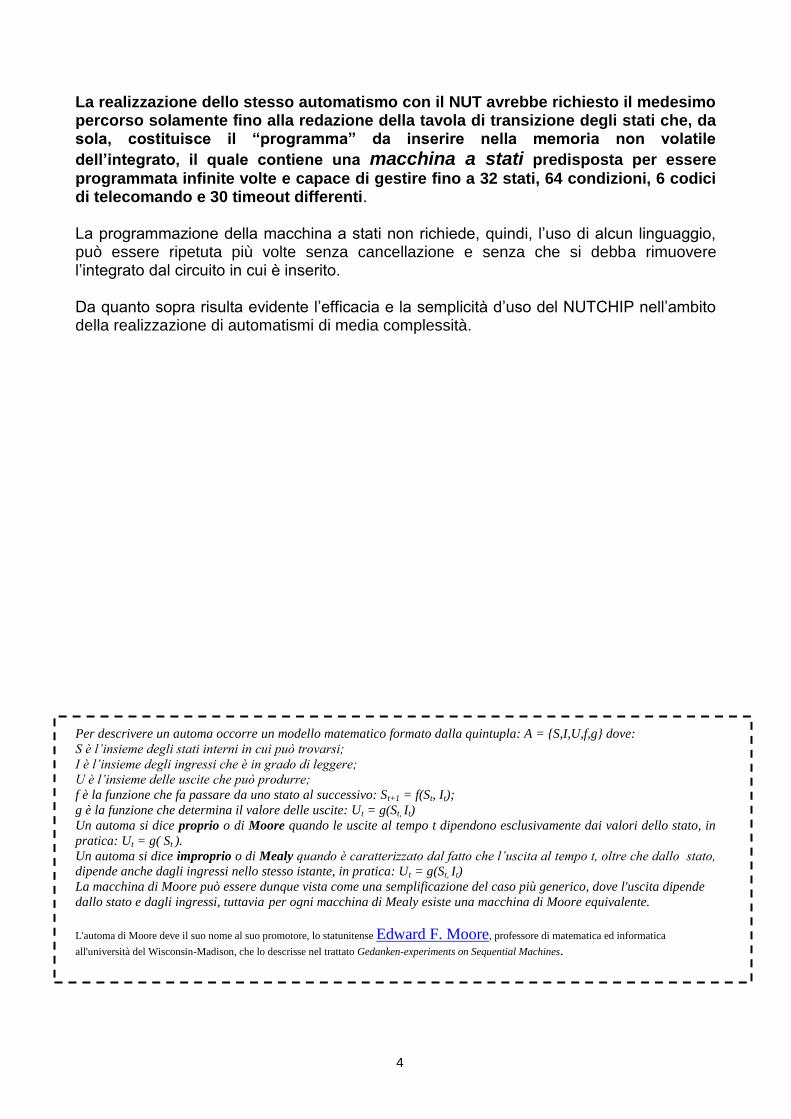
La realizzazione dello stesso automatismo con il NUT avrebbe richiesto il medesimo percorso solamente fino alla redazione della tavola di transizione degli stati che, da sola, costituisce il “programma” da inserire nella memoria non volatile
dell’integrato, il quale contiene una macchina a stati predisposta per essere
programmata infinite volte e capace di gestire fino a 32 stati, 64 condizioni, 6 codici di telecomando e 30 timeout differenti. La programmazione della macchina a stati non richiede, quindi, l‟uso di alcun linguaggio, può essere ripetuta più volte senza cancellazione e senza che si debba rimuovere l‟integrato dal circuito in cui è inserito. Da quanto sopra risulta evidente l‟efficacia e la semplicità d‟uso del NUTCHIP nell‟ambito della realizzazione di automatismi di media complessità.
Per descrivere un automa occorre un modello matematico formato dalla quintupla: A = {S,I,U,f,g} dove:
S è l’insieme degli stati interni in cui può trovarsi;
I è l’insieme degli ingressi che è in grado di leggere;
U è l’insieme delle uscite che può produrre;
f è la funzione che fa passare da uno stato al successivo: St+1 = f(St, It);
g è la funzione che determina il valore delle uscite: Ut = g(St, It)
Un automa si dice proprio o di Moore quando le uscite al tempo t dipendono esclusivamente dai valori dello stato, in
pratica: Ut = g( St ).
Un automa si dice improprio o di Mealy quando è caratterizzato dal fatto che l’uscita al tempo t, oltre che dallo stato,
dipende anche dagli ingressi nello stesso istante, in pratica: Ut = g(St, It)
La macchina di Moore può essere dunque vista come una semplificazione del caso più generico, dove l'uscita dipende
dallo stato e dagli ingressi, tuttavia per ogni macchina di Mealy esiste una macchina di Moore equivalente.
L'automa di Moore deve il suo nome al suo promotore, lo statunitense Edward F. Moore, professore di matematica ed informatica
all'università del Wisconsin-Madison, che lo descrisse nel trattato Gedanken-experiments on Sequential Machines.
4
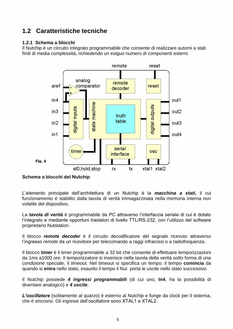
1.2 Caratteristiche tecniche 1.2.1 Schema a blocchi Il Nutchip è un circuito integrato programmabile che consente di realizzare automi a stati finiti di media complessità, richiedendo un esiguo numero di componenti esterni.
Schema a blocchi del Nutchip L‟elemento principale dell‟architettura di un Nutchip è la macchina a stati, il cui funzionamento è stabilito dalla tavola di verità immagazzinata nella memoria interna non volatile del dispositivo. La tavola di verità è programmabile da PC attraverso l‟interfaccia seriale di cui è dotato l‟integrato e mediante opportuni traslatori di livello TTL/RS-232, con l‟utilizzo del software proprietario Nutstation. Il blocco remote decoder è il circuito decodificatore del segnale ricevuto attraverso l‟ingresso remote da un ricevitore per telecomando a raggi infrarossi o a radiofrequenza. Il blocco timer è il timer programmabile a 32 bit che consente di effettuare temporizzazioni da 1ms a1000 ore. Il temporizzatore si inserisce nella tavola della verità sotto forma di una condizione speciale, il timeout. Nel timeout si specifica un tempo: il tempo comincia da quando si entra nello stato, esaurito il tempo il Nut porta le uscite nello stato successivo. Il Nutchip possiede 4 ingressi programmabili (di cui uno, In4, ha la possibilità di diventare analogico) e 4 uscite. L’oscillatore (solitamente al quarzo) è esterno al Nutchip e funge da clock per il sistema, che è sincrono. Gli ingressi dell‟oscillatore sono XTAL1 e XTAL2.
Fig. 4
5
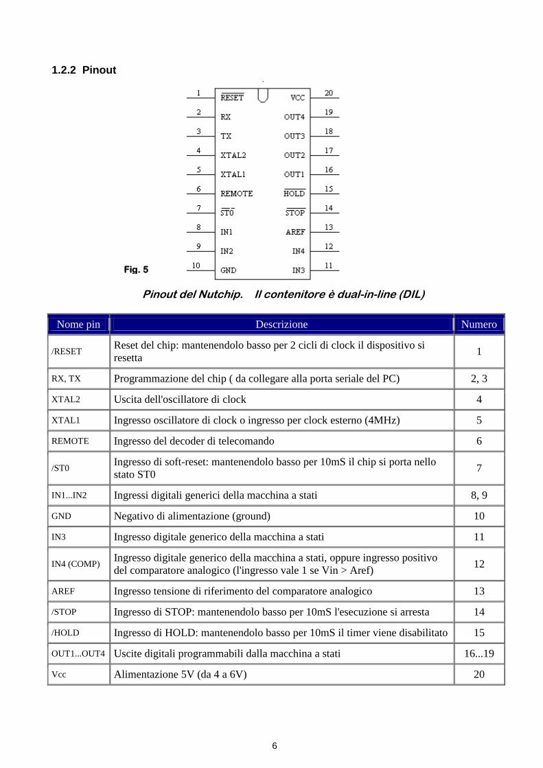
1.2.2 Pinout
Pinout del Nutchip. Il contenitore è dual-in-line (DIL)
Nome pin Descrizione Numero
/RESET Reset del chip: mantenendolo basso per 2 cicli di clock il dispositivo si
resetta 1
RX, TX Programmazione del chip ( da collegare alla porta seriale del PC) 2, 3
XTAL2 Uscita dell'oscillatore di clock 4
XTAL1 Ingresso oscillatore di clock o ingresso per clock esterno (4MHz) 5
REMOTE Ingresso del decoder di telecomando 6
/ST0 Ingresso di soft-reset: mantenendolo basso per 10mS il chip si porta nello
stato ST0 7
IN1...IN2 Ingressi digitali generici della macchina a stati 8, 9
GND Negativo di alimentazione (ground) 10
IN3 Ingresso digitale generico della macchina a stati 11
IN4 (COMP) Ingresso digitale generico della macchina a stati, oppure ingresso positivo
del comparatore analogico (l'ingresso vale 1 se Vin > Aref) 12
AREF Ingresso tensione di riferimento del comparatore analogico 13
/STOP Ingresso di STOP: mantenendolo basso per 10mS l'esecuzione si arresta 14
/HOLD Ingresso di HOLD: mantenendolo basso per 10mS il timer viene disabilitato 15
OUT1...OUT4 Uscite digitali programmabili dalla macchina a stati 16...19
Vcc Alimentazione 5V (da 4 a 6V) 20
Fig. 5
6

1.2.3 Caratteristiche funzionali
1.2.4 Caratteristiche elettriche
Valori massimi assoluti
Parametri in tensione continua
Voltaggio su ogni pin
(eccetto il reset) -1.0 a +7.0V
Tensione dell’ingresso
basso (V) -0.5….. (0,2 Vcc – 0,1)
Temperatura di
immagazinamento -40°C a 105°C
Tensione dell’ingresso
alto (V)
(0.2 Vcc + 0.9)…
…..(Vcc + 0,5)
Massima tensione di
lavoro 6.6V
Resistenze di pull-up
interne 35…100K ohm
Massima corrente in
uscita dai pin 40mA
Corrente in uscita
erogata 10 mA
Massima corrente da
Vcc a GND 140mA
Corrente in uscita
assorbita
20mA
CARATTERISTICHE FUNZIONALI
TELECOMANDO CODIFICA A RAGGI INFRAROSSI OPPURE VIA RADIO – FINO A 6 PULSANTI
TIMER DIGITALE DA 1 mS a 1000 h PROGRAMMABILE PASSO PER PASSO
FINO A 30 TEMPI DIFFERENTI PER PROGRAMMA
INGRESSI
4 DIGITALI PROGRAMMABILI
USCITE
4 DIGITALI PROGRAMMABILI - POTENZA: 5 V, 10 mA cad.
MATRICE DIGITALE PROGRAMMABILE
4 INGRESSI x 4 USCITE: FINO A 64 COMBINAZIONI DI INGRESSI FINO A 32 COMBINAZIONI DI USCITE
COMPARATORE ANALOGICO
A 2 INGRESSI PER TENSIONI DA 0 FINO A 5 V
INGRESSI SUPPLEMENTARI
- MARCIA/ARRESTO DEL TIMER - BLOCCO USCITE - RESET
FREQUENZA
4 MHz CON QUARZO OPPURE OSCILLATORE CERAMICO
ALIMENTAZIONE
5 VOLT (STABILIZZATA)
DIMENSIONI
CIRCUITO INTEGRATO A 20 PIEDINI D.I.L.
PROGRAMMAZIONE
PORTA SERIALE DEL PC TRAMITE ADATTATORE
SOFTWARE
NUTSTATION (GRATUITO PER USO NON COMMERCIALE)
Tab. 6
Tab. 7 Tab. 8
7

1.3 La tavola di verità
Il Nutchip è un sistema a stati finiti il cui funzionamento è descritto mediante una tabella di transizione degli stati (di seguito denominata “tavola di verità” per uniformità alla terminologia adottata dal costruttore del Nutchip), che viene memorizzata nella sua memoria interna; essa costituisce sostanzialmente il programma.
Come accade per moltissimi integrati digitali, anche per i Nutchip lo stato determina le uscite: i Nutchips sono integrati a stati. I Nutchips hanno quattro uscite: le uscite cambiano solo se anche lo stato cambia, per cui accanto ad ogni stato indicheremo anche la rispettiva combinazione di uscite. Per ogni stato, c'è la massima libertà nello stabilire quali uscite debbano essere a 0 e quali a 1.
Il Nut può, inoltre, gestire sei tasti (key1,…key6) di un eventuale telecomando attraverso l‟ingresso REMOTE. I pulsanti del telecomando sono da ritenersi a tutti gli effetti come altrettanti ingressi digitali.
Programmando un Nutchip si può inserire un trattino '-' (tre „---„ per l‟ingresso remote) quando non interessa specificare il valore di un ingresso. Il trattino '-' equivale alla X (don't care) che compare talvolta nella descrizione degli integrati commerciali. Un ingresso con il trattino è come se non esistesse e viene ignorato durante la valutazione della condizione.
I Nutchip contengono anche un preciso temporizzatore: per utilizzarlo lo si inserisce nella tavola sotto forma di timeout. Il timeout è una condizione che si verifica quando è passato il tempo caricato nel temporizzatore. Inserendo la condizione remaining il timer non viene azzerato quando si verifica una transizione di stato e la temporizzazione prosegue anche nello stato successivo. La modalità tempo rimanente consente di generare timeout che si estendono su più di uno stato e di realizzare timeout ciclici.
7
8
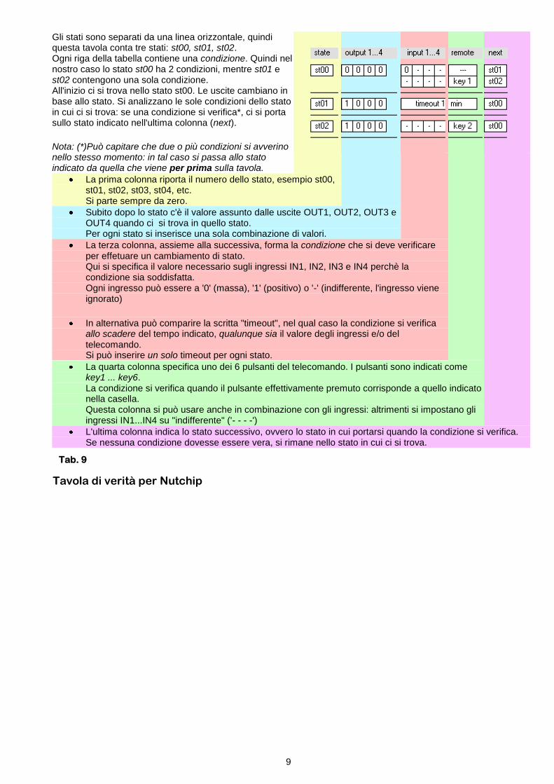
Tavola di verità per Nutchip
Gli stati sono separati da una linea orizzontale, quindi questa tavola conta tre stati: st00, st01, st02. Ogni riga della tabella contiene una condizione. Quindi nel nostro caso lo stato st00 ha 2 condizioni, mentre st01 e st02 contengono una sola condizione. All'inizio ci si trova nello stato st00. Le uscite cambiano in base allo stato. Si analizzano le sole condizioni dello stato in cui ci si trova: se una condizione si verifica*, ci si porta sullo stato indicato nell'ultima colonna (next).
Nota: (*)Può capitare che due o più condizioni si avverino nello stesso momento: in tal caso si passa allo stato indicato da quella che viene per prima sulla tavola.
La prima colonna riporta il numero dello stato, esempio st00, st01, st02, st03, st04, etc. Si parte sempre da zero.
Subito dopo lo stato c'è il valore assunto dalle uscite OUT1, OUT2, OUT3 e OUT4 quando ci si trova in quello stato. Per ogni stato si inserisce una sola combinazione di valori.
La terza colonna, assieme alla successiva, forma la condizione che si deve verificare per effetuare un cambiamento di stato. Qui si specifica il valore necessario sugli ingressi IN1, IN2, IN3 e IN4 perchè la condizione sia soddisfatta. Ogni ingresso può essere a '0' (massa), '1' (positivo) o '-' (indifferente, l'ingresso viene ignorato)
In alternativa può comparire la scritta "timeout", nel qual caso la condizione si verifica allo scadere del tempo indicato, qualunque sia il valore degli ingressi e/o del telecomando. Si può inserire un solo timeout per ogni stato.
La quarta colonna specifica uno dei 6 pulsanti del telecomando. I pulsanti sono indicati come key1 ... key6. La condizione si verifica quando il pulsante effettivamente premuto corrisponde a quello indicato nella casella. Questa colonna si può usare anche in combinazione con gli ingressi: altrimenti si impostano gli ingressi IN1...IN4 su "indifferente" ('- - - -')
L'ultima colonna indica lo stato successivo, ovvero lo stato in cui portarsi quando la condizione si verifica. Se nessuna condizione dovesse essere vera, si rimane nello stato in cui ci si trova.
Tab. 9
9

1.4 Il telecomando
Grazie ad un decoder interno, i Nutchip possono funzionare anche pilotati da un telecomando. Per utilizzare un telecomando basta aggiungere al circuito un ricevitore - oltre naturalmente al telecomando stesso.
I telecomandi sono oggi molto diffusi, e si trovano in commercio già pronti come pezzi di ricambio. Sono di due tipi: a radiofrequenza (utilizzati ad esempio negli apricancelli e negli antifurti) e a raggi infrarossi (TV, HiFi e videoregistratori).
I ricevitori sono particolari circuiti integrati o micromoduli che necessitano soltanto dell'alimentazione a 5 volt per funzionare. I più semplici sono i ricevitori ad infrarossi, simili ad un transistor. A dispetto delle apparenze offrono un funzionamento impeccabile ed una sensibilità eccellente. I ricevitori per telecomandi radio si trovano in commercio come moduli preassemblati, grandi poco più di un francobollo. Oltre al piedino di uscita (OUT) dove prelevare il segnale per la decodifica, vi sono altri piedini per l'alimentazione e l'eventuale antenna .
Ricevitore IR Temic/Vishay (f = 36 kHz)
Il decodificatore è incorporato nel Nutchip, ed è collegato al piedino REMOTE. Riconosce fino a 6 pulsanti diversi, con codici a piacere. Questi pulsanti, chiamati key1, key2, ..., key6, si possono inserire nella tavola della verità come se fossero dei pulsanti collegati realmente all‟integrato.
Il Nutchip è adatto sia per i codici usati dai telecomandi a radiofrequenza, sia per i codici usati dai telecomandi a infrarossi. Il segnale ricevuto dal telecomando si applica al piedino REMOTE del Nutchip.
Per completezza citiamo anche il telecomando virtuale Nutchip Commander, che simula un telecomando sullo schermo del PC. Non si tratta di un vero telecomando, ma di un comando via cavo (usa la porta seriale del PC invece dell'ingresso "REMOTE"). Si può usare da solo o insieme ad un telecomando ad infrarossi o via radio. In più, il Commander visualizza anche gli ingressi, le uscite e lo stato del Nutchip. Chiarite queste differenze, il Commander si adopera come un vero telecomando.
Telecomando Pc “Nutchip Commander”
Fig. 6
Fig. 7
10

1.5 La programmazione Il software shareware Nutstation è il software che consente di scrivere la tavola di verità e di programmare il Nutchip. All‟apertura del programma Nutstation consente di scegliere l‟attività da svolgere, e quindi l‟ambiente di lavoro. Esso rende possibile definire la tavola di verità (Tavola di verità) e di programmare l‟integrato (Prog. Chip). Nell‟ambiente di lavoro Tavola di verità è disponibile una barra degli strumenti le cui icone consentono di effettuare le funzioni generali indicate in tabella.
All‟avvio di Nutstation viene caricata l‟ultima tavola salvata. I pulsanti: “inserisci condizione”, “inserisci timeout”, “gomma” consentono di scrivere o cancellare nella riga attiva, evidenziata in giallo. Una volta completata la tabella della verità, si passa alla fase di programmazione del Nut, selezionando la finestra Prog. Chip; questa operazione attiva automaticamente la compilazione della tavola di verità nel linguaggio del Nutchip. Se durante la fase di compilazione vengono segnalati errori, si deve ritornare alla Tavola di verità e apportare le necessarie correzioni. Prima di procedere alla programmazione occorre effettuare il collegamento fra il Nut e una delle porte seriali del PC attraverso un circuito di interfaccia per l‟adattamento dei livelli di tensione opportunamente realizzato. Una volta programmato, il Nutchip manterrà memorizzata la tavola anche in assenza di alimentazione, l‟integrato può essere riprogrammato più volte senza che sia necessario cancellare la tavola precedentemente memorizzata. Nell‟ambiente di lavoro Prog. Chip sono presenti elementi che consentono di intervenire sul comparatore analogico interno (che permette di rendere analogico l‟ingresso In4) e sul telecomando. La tavola della verità identifica i tasti del telecomando numerandoli da key1 fino a key6. Ma il Nutchip come può sapere qual è veramente il primo tasto del telecomando, e quale codice trasmette?
Se si utilizza un telecomando standard, basta selezionarlo dall'elenco dei telecomandi disponibili. Se si vogliono utilizzare codici diversi, ad esempio un tasto non usato nel
Funzione
Nuova tavola: apre una nuova tavola di verità
Apre una tavola memorizzata su disco
Salva su disco la tavola corrente, con estensione .nut
Stampa la tavola di transizione corrente
Setup: imposta la porta seriale da usare per programmare il chip
Guida in linea: visualizza la guida di nutstation e dei nutchip.
Tab. 10
11

telecomando della TV o del videoregistratore, oppure un telecomando radio, occorre programmarlo.
Scegliendo i telecomandi personalizzati appare un telecomando stilizzato. Su di esso sono riportati i tasti da key1 a key6, e sopra a questi il codice relativo. Per modificare il codice associato ai key, basta fare click sul tasto relativo. Così è possibile associare ad ogni key un codice a piacere.
Nutstation dispone di una procedura detta di autoapprendimento che è il modo più semplice per assegnare i codici ai tasti del telecomando. Questa procedura si può anche utilizzare per verificare la compatibilità del telecomando con il Nutchip. Attivando questa modalità, che richiede l‟uso di un circuito già montato e funzionante, il Nut “apprende” automaticamente i codici trasmessi da sei tasti qualsiasi di un qualsiasi telecomando compatibile.
Un valido strumento per verificare una tavola di verità è il software shareware NutSim 1.3 che è un programma di simulazione per il Nutchip sviluppato da Massimo Negrotti, professore di Metodologia delle scienze umane all‟Università di Urbino.
Interfaccia grafica NutSim 1.3
Fig. 8
Fig. 9
12
Capitolo 2. Il cancello automatico 2.1 Specifiche di progetto
Un telecomando a raggi infrarossi comanda l‟apertura/chiusura, con angolo di 90°, di un cancello ad un‟anta azionato da un motore in corrente continua, secondo le seguenti modalità:
L‟apertura del cancello è comandata da un tasto del telecomando IR o da un pulsante
Il cancello rimane aperto per 30 s e poi si chiude automaticamente
È possibile comandare la chiusura del cancello prima che siano trascorsi 30 s, utilizzando un altro tasto del telecomando
Con il cancello in movimento lampeggia una lampada di segnalazione (T = 1 s) e un avvisatore acustico emette un suono intermittente (f = 1 KHz).
Quando il cancello è aperto, la lampada rimane accesa, l‟avvisatore acustico è disattivato.
Se si presenta un ostacolo durante la fase di chiusura, il cancello si ferma per tre secondi al fine di tenere conto dell‟inerzia meccanica del motore e poi si apre.
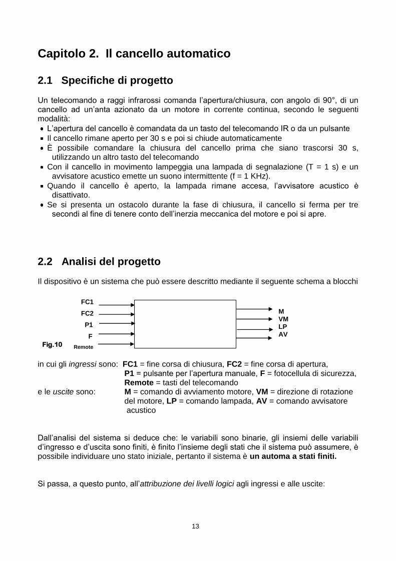
2.2 Analisi del progetto Il dispositivo è un sistema che può essere descritto mediante il seguente schema a blocchi in cui gli ingressi sono: FC1 = fine corsa di chiusura, FC2 = fine corsa di apertura, P1 = pulsante per l‟apertura manuale, F = fotocellula di sicurezza, Remote = tasti del telecomando e le uscite sono: M = comando di avviamento motore, VM = direzione di rotazione del motore, LP = comando lampada, AV = comando avvisatore acustico Dall‟analisi del sistema si deduce che: le variabili sono binarie, gli insiemi delle variabili d‟ingresso e d‟uscita sono finiti, è finito l‟insieme degli stati che il sistema può assumere, è possibile individuare uno stato iniziale, pertanto il sistema è un automa a stati finiti. Si passa, a questo punto, all‟attribuzione dei livelli logici agli ingressi e alle uscite:
M VM LP AV
FC1
FC2
P1
F
Remote Fig.10
13

INGRESSI 0 = interruttore chiuso FC1 = fine corsa di chiusura 1 = interruttore aperto 0 = interruttore chiuso FC2 = fine corsa di apertura 1 = interruttore aperto 0 = pulsante premuto P1 = pulsante per apertura manuale
1 = pulsante rilasciato 0 = assenza di ostacolo F = fotocellula 1 = presenza di ostacolo Remote Key 1 = apertura, Key 2 = chiusura Si hanno, pertanto, le seguenti combinazioni degli ingressi: USCITE 0 = motore fermo M = alimentazione motore 1 = motore in marcia 0 = rotazione oraria (apertura cancello) VM = verso di rotazione del motore
1 = rotazione antioraria (chiusura cancello) 0 = lampada spenta LP = comando lampada 1 = lampada accesa 0 = avvisatore acustico spento AV = comando avvisatore acustico
1 = avvisatore acustico attivo Si avranno quindi i seguenti stati:
Stato M VM LP AV
0 0 0 0 0 Cancello chiuso
1 1 0
1 0 Apertura
4 0 1
2 1 1
1 0 Chiusura
5 0 1
3 0 1 1 0 Cancello aperto
6 0 0 1 0 Cancello fermo
FC1 FC2 P1 F Remote Condizione
0 1 1 0 --- Cancello chiuso
1 0 1 0 --- Cancello aperto
1 1 1 0 --- Cancello in movimento
1 1 0 0 --- Apertura manuale
- - - - Key 1 Comando di apertura
- - - - Key 2 Comando di chiusura
- - - 1 --- Apertura per intervento fotocellula Tab.11
14
Tab.12

Il funzionamento del sistema può essere rappresentato nel precedente diagramma di transizione degli stati, in cui le variabili d‟ingresso e d‟uscita hanno l‟ordine indicato nella figura seguente:
St. n/(M,VM,LP,AV)n FC1, FC2, P1, F, Remote St. n+1/(M,VM,LP,AV)n+1
Il diagramma di transizione degli stati viene riportato, in Nutstation, nella tabella di transizione che costituisce il programma del Nutchip
St. 4/ 1,0,0,1
St. 0/0,0,0,0
St. 5/1,1,0,1
St. 3/0,1,1,0
St. 1/1,0,1,0
St. 6/0,0,1,0
St. 2/1,1,1,0
APERTURA
APERTURA
APERTO
FERMO
CHIUSURA CHIUSURA
CHIUSO
1,0,1,X
1,0,1,X
TO 0,5 sec
TO 0,5 sec
X,X,X,X,Key1
1,1,0,X
TO 3sec
TO 30sec
X,X,X,X,key2
0,1,1,X
0,1,1,X
X,X,X,1
X,X,X,1
TO 0,5 sec TO 0,5 sec
Fig.11
Fig.12
15

Il programma, prima simulato con NutSim 1.3, viene trasferito nella memoria del circuito integrato.
16
Tab.13

2.3 Interfaccia di programmazione Il nutchip viene collegato al Pc attraverso l‟interfaccia seriale RS232. L‟RS232 può effettuare tutte le modalità di trasmissione e consente altresì il collegamento tramite modem (remoto) o senza - null modem - (non remoto). Poiché L‟RS232 lavora in logica negativa abbiamo la necessità di adattare i livelli logici attraverso opportuni integrati, uno dei più usati è il MAX232. Il Max 232 contiene:
Due line driver che convertono segnali TTL/CMOS in segnali conformi allo standard dell‟RS232.
Due line receiver che convertono segnali RS232 in segnali TTL/CMOS L‟integrato è dotato di circuiti (pompa di carica) che provvedono a elevare la tensione da 5 a 10 Volt e a invertirla per ottenere i valori di tensione RS232.
Interfaccia di programmazione
ELENCO COMPONENTI
Sigla di riferimento Valore Caratteristiche
C1, C2, C3, C4 10 μF elettrolitico 25 V
C5 100 nF plastico
IC1 MAX 220 Trasm./Ricev. Multicanale RS232
FC1, FC2 Interruttori di fine corsa N.A.
P1 Pulsante N.A.
OSC 4 MHz Risuonatore ceramico muRata
Ricevitore IR 36KHz TK1836
C6 10 μF elettrolitico 25 V
R7 47 Ω ¼ W
IC2 NUT-01-AK Nutchip
Fig.13
Tab.14
17
Connettore seriale Rs-232 DB9-fem Finecorsa FC1 e FC2
2.4 Interfaccia Lampada
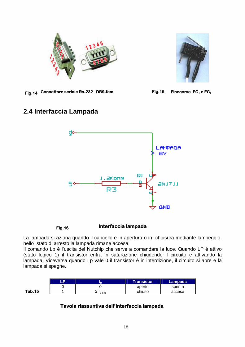
Interfaccia lampada La lampada si aziona quando il cancello è in apertura o in chiusura mediante lampeggio, nello stato di arresto la lampada rimane accesa. Il comando Lp è l‟uscita del Nutchip che serve a comandare la luce. Quando LP è attivo (stato logico 1) il transistor entra in saturazione chiudendo il circuito e attivando la lampada. Viceversa quando Lp vale 0 il transistor è in interdizione, il circuito si apre e la lampada si spegne.
Tavola riassuntiva dell’interfaccia lampada
LP Ib Transistor Lampada
0 0 aperto spenta
1 ≥ Ib sat chiuso accesa
Fig.14
18
Fig.15
Fig.16
Tab.15

2.5 Interfaccia avvisatore acustico
Interfaccia avvisatore acustico L‟NE555 è un circuito integrato che, in configurazione astabile, genera un onda quadra a una frequenza e duty cycle determinati dai valori dei componenti esterni Ra, Rb, C1 Per il periodo:
Tonda generata = 0.7 (Ra+2Rb) C1
msgenTon 11010)10682108,6(7,0.. 933
Per il duty cycle invece :
d.c. = (Ra + Rb)/(Ra+2Rb) 5,010682108,6
1068108,6..
33
33
cd
L‟onda quadra viene generata dal pin 3 OUT dell‟integrato. Nel caso del cancello occorre generare un‟onda quadra a una frequenza di 1 KHz con un‟ampiezza di 5 Volt (determinata dall‟alimentazione dell‟integrato). Il pin 4 è il RESET dell‟integrato che viene comandato dal nutchip. Il reset (attivo basso) serve a comandare l‟impulso in uscita. Quando il reset è a 0 (555 disabilitato) l‟onda quadra non viene generata. Viceversa quando è a 1 l‟onda quadra viene generata secondo le regole indicate sopra. Si ha, pertanto, il funzionamento rappresentato nelle seguenti forme d‟onda.
t
T = 1ms
t T = 1s
AV
Vout, 555
19
Fig.17
Fig.18

2.6 Interfaccia Motore
Interfaccia motore
ELENCO COMPONENTI
Questa interfaccia è composta da due relè comandati da due transistor usati come interruttori elettronici. I transistor Q1 e Q2 a loro volta vengono comandati rispettivamente dalle uscite M (azionamento motore) e VM ( inversione di marcia) del nutchip. Quando Q1 è in saturazione si comporta come un interruttore chiuso e alimenta la bobina che a sua volta, chiudendo il contatto j1, alimenta il secondo relè (e quindi il motore). Il verso di rotazione del motore è determinato dallo stato logico del segnale VM che agisce sul transistor Q2.
Per il motore si è scelto un modello a magnete permanente alimentato a 5 volt e dotato di riduttore per il numero dei giri. Per tale motore si ha velocità di rotazione ω = K Valimentazione [giri/min.] dove K è una costante che tiene conto delle caratteristiche del motore.
Sigla di riferimento Valore Caratteristiche
d1, d2 1N4004 diodo
R1, R2 10KΩ ¼ W
Q1, Q2 BC517 BJT npn darlington
Relè1, Relè2 rele‟ subminiatura DIL 2A 2CO DPDT
20
Fig.19
Tab.16

2.7 Interfaccia fotocellula Il sensore è basato su un led a emissione infrarossa che, nel momento in cui viene attraversato da corrente,emette un cono di luce nello spettro dell‟infrarosso (ovvero di lunghezza d‟onda compresa tra 1 mm e 700 nm e frequenza compresa tra 300 GHz e 428 THz non visibile all‟occhio umano) e su un fototransistor sensibile alla medesima frequenza. In quest‟ultimo si crea un flusso di corrente tra collettore ed emettitore proporzionale all‟energia della radiazione ricevuta in base.
c
λ = lunghezza d’onda
c = velocità della luce = 3,0 •108 m/sec
ν = frequenza
Spettro elettromagnetico
Con l‟aumentare della luminosità, il fototransistor aumenta la corrente di collettore fino a raggiungere la saturazione e a comportarsi come un circuito chiuso, mentre quando è posto in “ombra” va in interdizione ed equivale ad
Spettro luminoso un circuito aperto. Il sensore è diviso in due parti distinte: la prima, caratterizzata dal led, ha funzione di circuito emettitore di raggi infrarossi, mentre la seconda, caratterizzata dal fototransistor, svolge il ruolo di ricevitore del segnale. L‟uscita di quest‟ultimo circuito, costituita da un segnale binario compreso tra circa zero (assenza di ostacolo) e circa 5 Volt (presenza di ostacolo), viene mandata all‟ingresso In4 del Nutchip (poiché è stato utilizzato un circuito esistente, costruito per un precedente progetto, non è stato sfruttato il comparatore analogico interno al Nut, pur essendo questa la scelta opportuna).
21
Fig.20
Fig.21
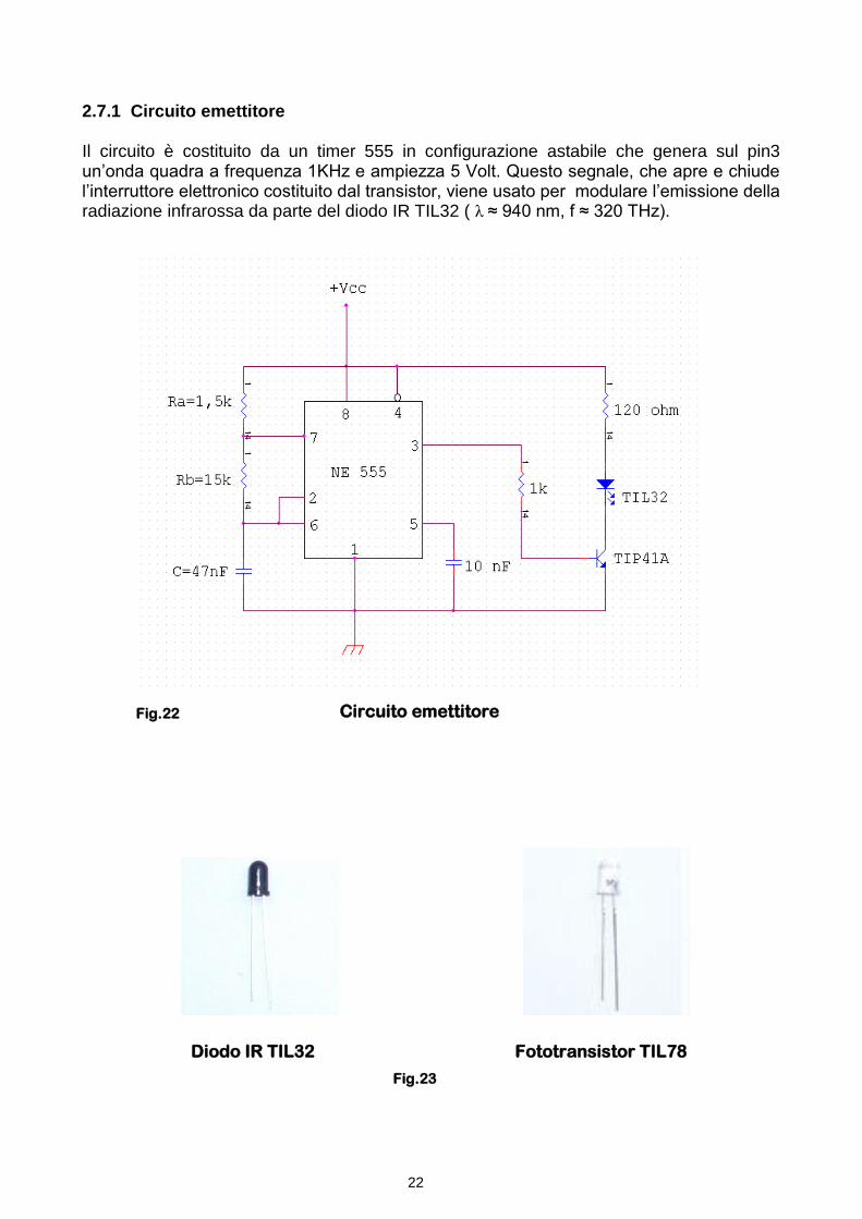
2.7.1 Circuito emettitore Il circuito è costituito da un timer 555 in configurazione astabile che genera sul pin3 un‟onda quadra a frequenza 1KHz e ampiezza 5 Volt. Questo segnale, che apre e chiude l‟interruttore elettronico costituito dal transistor, viene usato per modulare l‟emissione della radiazione infrarossa da parte del diodo IR TIL32 ( λ ≈ 940 nm, f ≈ 320 THz). Circuito emettitore Diodo IR TIL32 Fototransistor TIL78
Fig.22
Fig.23
22

2.7.2 Circuito ricevitore In condizione di “buio” il fototransistor (TIL 78) è interdetto e il condensatore si carica con costante di tempo
[τc = (R1+R2+R3)xC] compresa tra 1 ms (pot. = 0 Ω) e 100 ms (pot. = 106
Ω) mentre la tensione Vc max può
variare tra 4,5 V e 0,45 V. In condizioni di “luce” il fototransistor è saturato e il condensatore si scarica con costante di tempo
[τs = R3xC] pari a 3,3 μs.
Il susseguirsi di condizioni di “buio” e “luce” a frequenza 1 KHz, quindi con durata del semiperiodo pari a 500 μs, impedisce la carica totale del condensatore, mantenendo in ogni caso la tensione Vc al di sotto del valore 2,5 Volt; solo quando la presenza di un ostacolo mantiene il transistor in condizione di “buio” per un tempo superiore a 0,5 ms, il condensatore può caricarsi oltre tale limite. La tensione Vc viene confrontata dal comparatore con un valore di tensione fissato dal partitore resistivo; il confronto fornisce uscita alta quando la soglia viene superata (presenza di ostacolo), questo segnale, limitato dal diodo zener a +5V, costituisce l‟In4 del Nutchip.
Circuito ricevitore
No ostacolo IR IR IR
5V
Ostacolo
no IR no IR no IR
0V
t
0,5 m/sec 0,5m/sec
500 μ/sec 500 μ/sec
Vc max =4,5V
Vc =2,5V
0V
Forme d’onda del circuito ricevitore
23
Fig.24
Fig.25

Chapter 1. The Nutchip
1.1 The theoretical assumptions: the finite state automaton
In the study of system it‟s necessary to individualize the quantities susceptible of modifications, defined variables of the system.
We can distinguish these as follows:
Input variables: solicitations that can be varied directly by man‟s interference
Output variables: the actions with which influence the environment
State or internal variables: they are the quantities that describe the evolution of the system, they
contain information on its past history and determine the future states
Noise variables: stresses which cannot be manipulates
If a sequential system, with memory, has a finite set of internal state, of input and output variables, if it possible to identify a starting and a finish state, this is defined Finite State Automaton.
More precisely we define Finite State Automaton a dynamic system, discrete and invariant, in which the
input-output and the state variables are a finite number.
The synthesis of logical sequential circuits, carried out through automaton becomes, when we draw from simple models, complex and, for this reason, has lost efficacy whit the introduction of the logical programmable systems in which the functions that a system must perform are carried out by a program that controls a µP, a PLC or better a µcontroller.
The integrate circuit Nutchip, through which we achieved our project (which is a finite state automaton of medium complexity), intervenes in this context in which it represents an alternative mean both to the manual design of sequential machine and the need to implement specific software, which requires at least the knowledge of the a programming language used by the device chosen.
The following example aims to clarify the role of Nut in the process of synthesis and management of a
control system.
We want to build a Moore‟s automaton (see box) that automate the functioning of a system consisting of an input which is connected to a switch and a output which is connected to a led. The system has to change the state whenever the switch gives a transition from low to high level.
The system can be described by the following block diagram.
Picture 1
by the following diagram of states
Picture 2
and the corresponding table of transition states
Table 1
From the above table we come to another which gives the values of the state variables (within square brackets) in each transition.
Table 2
24

For the synthesis we should use two FF, being four the states and two the state variables.
Using D FF-type is now possible to draw the Karnaugh‟s maps regarding D1 and D0, coinciding the transition and the excitation tables: Qn+1(t) = Dn(t)
Table 3 Table 4
We must build the synthesis of the combinatorial output net (the outputs of the FF becomes the inputs of the network that excites the led). Following Moore‟s theory the excitement of the output network does not depend from the input.
From the table we obtain: 0101 QQQQU Table 5
We finally realize the circuit, which is in the picture 3
Picture 3
The solution of this very easy example gives us the idea of complexity of the procedure that must be followed in the “manual” synthesis of a sequential system, that will then create equally complex circuits, very difficult to be built.
The realization of the same automatism with the Nut would have required same procedure only until the drawing up of the transition table of the states that, by itself, is the program to be included in the memory of the I.C., that contains a “state machine” designed to be programmed countless times and able to manage up to 32 states, 64 conditions, 6 codes for remote controls and 30 different timeout.
The programming of the state machine doesn‟t require, therefore, the use of any language, it can be repeated several times without deletion and without having to remove the integrated from the circuit in which it is inserted.
The effectiveness and simplicity of use of the Nutchip in the realization of medium complexity automatisms is evident from what we said above.
To describe an automaton we require a mathematical model made up of five variables: A = { S,I,U,f,g } where:
S is the set of inner states in which it may be;
I is the set of of inputs that it is able to read;
U is the set of of outputs that it can produce;
f is the function that switches from one state to the next: St+1 = f(St, It);
g is the function that determines the value of outputs: Ut = g(St, It)
An automaton is called proper or Moore’s when the output at time t depend only on the values of the state, in practice:
Ut = g( St ).
An automaton is called improper or Mealy’s when it is characterized by the fact that the outputs at time t, as well as on the state, also depends on the inputs at the same time, in practice: Ut = g(St, It)
Moore’s machine can therefore be seen as a simplification of the more general case, where the output depends on the state and the inputs, however for each Mealy’s machine there is an equivalent Moore’s machine.
Moore‟s automaton is called after its promoter, the American Edward F. Moore, professor of Mathematics and Computer Science at the University of Wisconsin-Madison , who described it in the Treaty Gedanken-experiments on Sequential Machines.
25

1.2 Specifications
1.2.1 Block diagram
The Nutchip is a programmable integrated circuit that allows to create finite state automaton of mediun complexity, requiring very few external components.
Picture 4
The main elements of a Nutchip is the machine state, whose operation is determined by the truth table stored in the non-volatile memory of the device. The truth table is programmable by a PC via the serial interface that the integrated circuit have and by appropriate translator TTL/RS-232 level, with the use of the specific software Nutstation. The block remote decoder is the decoder circuit of the signal received through the “remote” input from an infrared or radio frequency remote control receiver. The timer block is a 32 bit programmable timer that let you perform timings from 1 ms to 1000 hours. The timer is in the truth table in the form of a special condition: the “timeout”. In the timeout we specify an interval of time which begins when you enter the state; this time spent, the Nut puts the outputs in the next state. The Nutchip has four programmable inputs (one of which, IN4, has the opportunity to become analogue) and four outputs. The oscillator (usually made of quartz) is external to the chip and is the system‟s clock. The oscillator input are XTAL1 and XTAL2.
1.2.2 Pinout
Picture 5 Chip pinout, dual-in-line plastic case
26
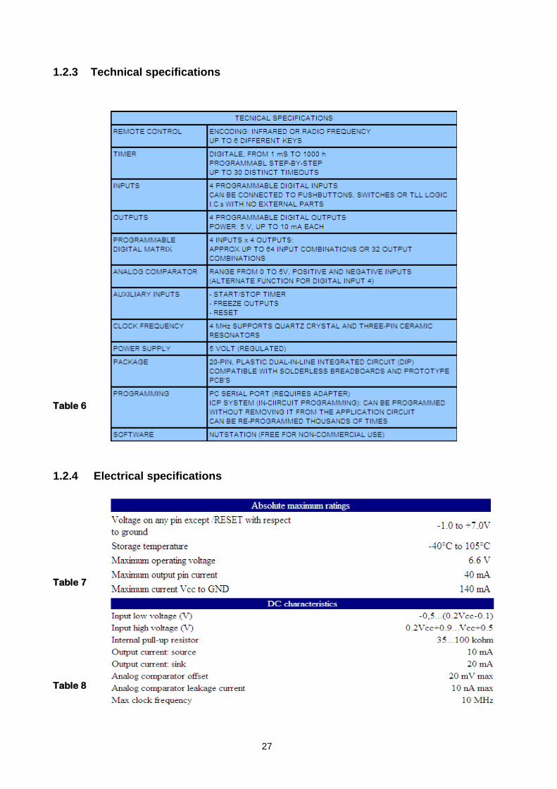
1.2.3 Technical specifications
Table 6
1.2.4 Electrical specifications
Table 7
Table 8
27
1.3 The truth table
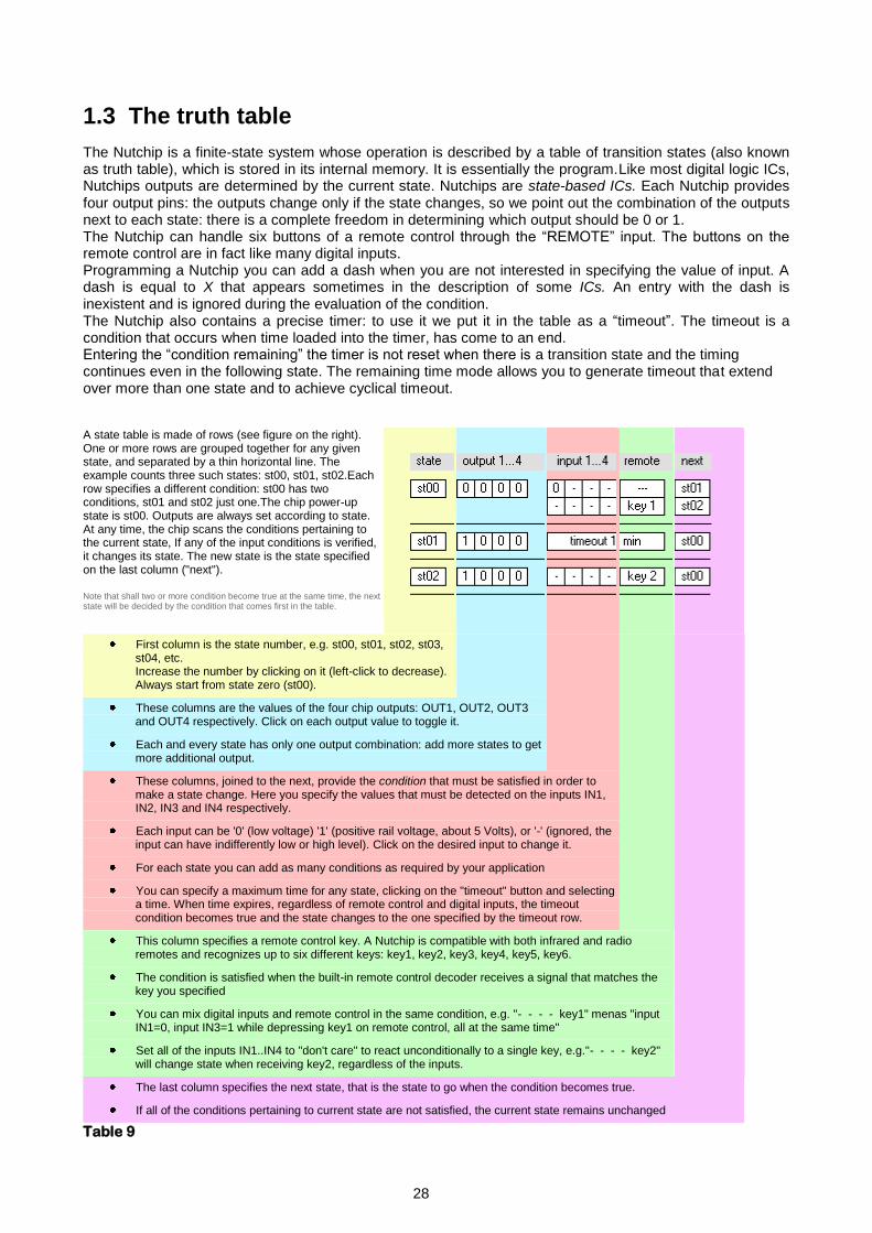
The Nutchip is a finite-state system whose operation is described by a table of transition states (also known as truth table), which is stored in its internal memory. It is essentially the program.Like most digital logic ICs, Nutchips outputs are determined by the current state. Nutchips are state-based ICs. Each Nutchip provides four output pins: the outputs change only if the state changes, so we point out the combination of the outputs next to each state: there is a complete freedom in determining which output should be 0 or 1. The Nutchip can handle six buttons of a remote control through the “REMOTE” input. The buttons on the remote control are in fact like many digital inputs. Programming a Nutchip you can add a dash when you are not interested in specifying the value of input. A dash is equal to X that appears sometimes in the description of some ICs. An entry with the dash is inexistent and is ignored during the evaluation of the condition. The Nutchip also contains a precise timer: to use it we put it in the table as a “timeout”. The timeout is a condition that occurs when time loaded into the timer, has come to an end. Entering the “condition remaining” the timer is not reset when there is a transition state and the timing continues even in the following state. The remaining time mode allows you to generate timeout that extend over more than one state and to achieve cyclical timeout.
A state table is made of rows (see figure on the right). One or more rows are grouped together for any given state, and separated by a thin horizontal line. The example counts three such states: st00, st01, st02.Each row specifies a different condition: st00 has two conditions, st01 and st02 just one.The chip power-up state is st00. Outputs are always set according to state. At any time, the chip scans the conditions pertaining to the current state, If any of the input conditions is verified, it changes its state. The new state is the state specified on the last column ("next").
Note that shall two or more condition become true at the same time, the next state will be decided by the condition that comes first in the table.
First column is the state number, e.g. st00, st01, st02, st03, st04, etc. Increase the number by clicking on it (left-click to decrease). Always start from state zero (st00).
These columns are the values of the four chip outputs: OUT1, OUT2, OUT3 and OUT4 respectively. Click on each output value to toggle it.
Each and every state has only one output combination: add more states to get more additional output.
These columns, joined to the next, provide the condition that must be satisfied in order to make a state change. Here you specify the values that must be detected on the inputs IN1, IN2, IN3 and IN4 respectively.
Each input can be '0' (low voltage) '1' (positive rail voltage, about 5 Volts), or '-' (ignored, the input can have indifferently low or high level). Click on the desired input to change it.
For each state you can add as many conditions as required by your application
You can specify a maximum time for any state, clicking on the "timeout" button and selecting a time. When time expires, regardless of remote control and digital inputs, the timeout condition becomes true and the state changes to the one specified by the timeout row.
This column specifies a remote control key. A Nutchip is compatible with both infrared and radio remotes and recognizes up to six different keys: key1, key2, key3, key4, key5, key6.
The condition is satisfied when the built-in remote control decoder receives a signal that matches the key you specified
You can mix digital inputs and remote control in the same condition, e.g. "- - - - key1" menas "input IN1=0, input IN3=1 while depressing key1 on remote control, all at the same time"
Set all of the inputs IN1..IN4 to "don't care" to react unconditionally to a single key, e.g."- - - - key2" will change state when receiving key2, regardless of the inputs.
The last column specifies the next state, that is the state to go when the condition becomes true.
If all of the conditions pertaining to current state are not satisfied, the current state remains unchanged
Table 9
28

1.4 The remote control
Through an internal decoder, the Nutchip can work also driven by a control. To use a remote control it‟s sufficient to add to a receiver to a circuit and, of course, a remote control.
The remote controls are very popular, and we can find them on the market, ready to be used as spare parts.
They are of two types: a radio frequency ones (used in car alarms and gate openings) and infrared ones (TV, HiFi e video recorders).
Receivers are particular integrate circuits needing 5 Volts to work. The simplest ones are the infrared receivers, similar to a transistor. They offer a flawless operation and excellent sensitivity.
Receivers for radio remote controls are on the market already assembled, just a little larger than a postage stamp. In addition to a pin output (OUT) which takes the signal to decode, there are other pins for the power and the aerial.
Picture 6
The decoder is embedded in the Nutchip, and is connected to REMOTE pin. It recognizes up to six different buttons with desired cedes. These buttons are called key1, key2,… key6; you can enter them in the truth table as if they were actually connected to the inputs of the chip.
The Nutchip is suitable for the codes used both by radio frequency and infrared remote controls. The signal received from the remote control is applied to the REMOTE pin of the Nut.
To be precise we also mention the virtual remote control “Nutchip Commander”, which simulates a remote control on your PC. This is not a true remote control, but a command via the cable (it uses the serial port of the PC instead of the input REMOTE).
You can use it alone or together with an infrared or via radio remote control. In addition, the Commander also displays the inputs, outputs and the states of the Nutchip.
Clarified these differences, the Commander can be used as a true remote control.
Picture 7
1.5 The programming
The shareware software “Nutstation” is a software that allow you to write the truth table and to plan the Nutchip. When you launch the program Nutstation, it lets you choose the activities to be preformed, and thus the work environment.
It makes possible to define the truth table (Truth table) and to program the Nutchip (Prog. Chip). In the working Truth table there is a toolbar with icons which allow you to perform the functions indicated in the table.
NEW TABLE: erases current truth table and resets the system for a new one
OPEN FILE: aborts current truth table and replaces it with a new one from a disk file ( .nut files)
SAVE AS: saves a copy of the current table on a disk file
PRINT: prints current truth table to the Window's system printer
SETUP: sets the language and the serial port to be used for chip programming
GUIDE: shows guide
Table 10
29
When you enter Nutstation, you can see the least saved table.
Once you have completed the truth table, you go on programming chip, by selecting the window Prog. Chip;
this automatically activates the compilation of the truth table in the language of the Nutchip.
If during the compilation errors occur, you must go back to the truth table and make every necessary corrections.
Before programming you need to connect the Nut to a serial port of the PC through an interface circuit for the adaptation of the voltage levels, properly implemented.
Once programmed, the Nutchip will keep the table stored even in absence of power, the ICs can be reprogrammed many times without clearing the table previously stored.
In the Prog. Chip there are some elements that allow you to act on the internal analogue comparator and on
the remote control.
The truth table identifies the buttons on the remote controls numbering then from key1 to key6. But how can the Nut really know what the first button on the remote control is and which code it transmits?
If you use a standard remote control, simply select it from the available remote control. If you want to use different codes, for example a button which is not used in a TV or video-recorder remote control, you must reprogram it.
Selecting custom IRED remote controls, we can see a stylized remote control on the monitor where there are the buttons from Key 1 to Key 6, and on top of them there are their code. To change the code associated with the key just to click on the button itself, so you can give each key a code at will.
Picture 8
The Nutststion has a procedure know as “self taught” which is the easiest way to give the codes to the keys of the remote control. This procedure can also be used to verify the compatibility of a remote control with the Nutchip. Activating this procedure, which require the use of a circuit already installed and running, the Nut “learns” the codes automatically transmitted by the six keys of any compatible remote control.
A valuable tool for examining a truth table is the shareware software NutSim1.3 which is a simulation program for the Nutchip developed by Massimo Negrotti, professor of Methodology of Social Sciences at the University of Urbino.
Picture 9
30

Chapter 2. The automatic gate
2.1 Project specifications
An infrared remote control orders the opening / closing, with an angle of 90 °, of one shutter gate moved by a CC motor, as follows: - The opening of the gate is controlled by a key on the IR remote control or by a button - The gate remains opened for 30 seconds and then it closes automatically - It‟s possible to control the closing of the gate within the 30 seconds using a key on the remote control - When the gate is moving a warning lamp flashes (T = 1s) and a horn emits an intermittent sound (f = 1 KHz) - When the gate is open, the lamp is on and the horn is off. - If an obstacle appears during the closing, the gate will stop for three seconds to take the mechanic inertia of the motor in to consideration and then it opens again.
2.2 Analysis of project
The device is a system that can described by the following block diagram:
Picture 10
where the inputs are: FC1 = closing limits switch, FC2 = opening limits switch, P1 = manual button, F = photocell, REMOTE = keys of the remote control. and outputs are: M = command starter motor, MV = direction of rotation of the engine, LP = control lamp, AV = command horn. From the analysis of the system we can conclude that: the variables are binary, the set of variables for input and output are finite the set of the states is over, it is possible to find the starting state; therefore the system is a finite state automaton. Then we give logic values to inputs and outputs. INPUTS 0 = closed switch FC1 = closing limits switch 1 = open switch
0 = closed switch FC2 = opening limits switch 1 = open switch 0 = pushed button P1 = manual opening button
1 = released button
0 = present obstacle F = photocell 1 = absent obstacle Remote Key 1 opens, Key 2 closes
31

Therefore you will have the following inputs:
Table 11
OUTPUTS 0 = stationary engine M = engine power 1 = running engine
0 = clock wise direction (opening gate) VM = direction of engine rotation 1 = anti-clock direction (closing gate) 0 = lamp off LP = lamp control 1 = lamp on
0 = horn off AV = horn control 1 = horn on You will have the following states:
Table 12
Picture 11
The functioning system can be represented by the flow chart of the transition states, in which the input and output variables are in the order shown in the picture below.
Picture 12
The flow chart of the transition states is represented, in the Nutstation, in the transition table that is the program of the Nutchip.
Table 13
The program, first simulated with Nutsim 1.3, is stored in the integrated circuit memory.
FC1 FC2 P1 F Remote Condition
0 1 1 0 --- Closed gate
1 0 1 0 --- Open gate
1 1 1 0 --- Moving gate
1 1 0 0 --- Manual opening
- - - - Key 1 Opening control
- - - - Key 2 Closing control
- - - 1 --- Photocell opening
State M VM LP AV
0 0 0 0 0 Closed gate
1 1 0
1 0 Opening
4 0 1
2 1 1
1 0 Closing
5 0 1
3 0 1 1 0 Open gate
6 0 0 1 0 Motionless gate
32
2.3 Programming interface The Nutchip is connected to Pc via the serial interface RS-232. The RS-232 can make all the arrangements for the transmission and allows the connection through modem (remote) or null- modem (not remote). The RS-232 works in negative logic we need to adapt the logic levels thorugh appropriate integrated circuit, one of the most used is the MAX-232 The MAX-232 contains: -Two line drivers that convert signals TTL/CMOS into signals consistent with the standard of RS-232 -Two line receivers that convert signals RS-232 into TTL/CMOS signals. The integrated is provided with circuits that arrange for the raising of the voltage from 5 to 10 volts and for the reversing of it to get the values of RS-232 voltage.
Picture 13
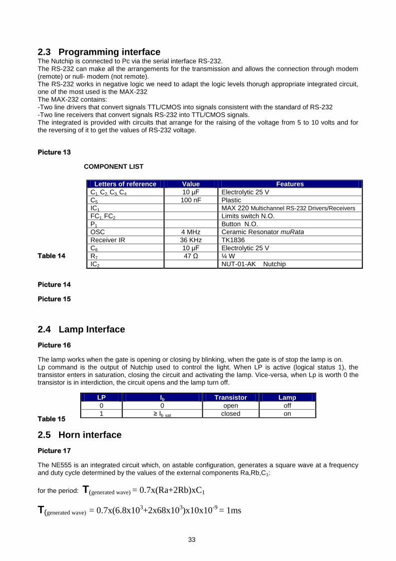
COMPONENT LIST
Table 14
Picture 14
Picture 15
2.4 Lamp Interface
Picture 16
The lamp works when the gate is opening or closing by blinking, when the gate is of stop the lamp is on. Lp command is the output of Nutchip used to control the light. When LP is active (logical status 1), the transistor enters in saturation, closing the circuit and activating the lamp. Vice-versa, when Lp is worth 0 the transistor is in interdiction, the circuit opens and the lamp turn off.
Table 15
2.5 Horn interface
Picture 17
The NE555 is an integrated circuit which, on astable configuration, generates a square wave at a frequency and duty cycle determined by the values of the external components Ra,Rb,C1:
for the period: T(generated wave) = 0.7x(Ra+2Rb)xC1
T(generated wave) = 0.7x(6.8x103+2x68x103)x10x10-9 = 1ms
Letters of reference Value Features
C1, C2, C3, C4 10 μF Electrolytic 25 V
C5 100 nF Plastic
IC1 MAX 220 Multichannel RS-232 Drivers/Receivers
FC1, FC2 Limits switch N.O.
P1 Button N.O.
OSC 4 MHz Ceramic Resonator muRata
Receiver IR 36 KHz TK1836
C6 10 μF Electrolytic 25 V
R7 47 Ω ¼ W
IC2 NUT-01-AK Nutchip
LP Ib Transistor Lamp
0 0 open off
1 ≥ Ib sat closed on
33

for the duty cycle instead: d.c. = (Ra+Rb)/(Ra+2Rb) 0,5
The square wave is generated from pin 3 out of the I.C. For the gate it is necessary to generate a square wave with a frequency of 1KHz with an amplitude of 5 volts (determined by the power of I.C.).The pin 4 is the reset of I.C., which is controlled by the Nutchip. The reset (active low) is used to control the output pulse. When the reset is 0 ( 555 off ) the square wave is not generated. When it is work 1 we have the wave is generated in accordance with the rules given above. Therefore, we have the operation represented in the following picture of waveforms.
Picture 18
2.6 Engine interface
Picture 19
COMPONENT LIST
Table 16
This interface consists of two relays controlled by two transistors used as electronic switches. The transistors Q1 and Q2 in turn are controlled respectively by the output M and VM of the Nutchip. When Q1 is in saturation it behaves like a closed switch and it supplies the coil which in turn, closing the contact j1, feeds the second relay (and hence the engine). The direction of the engine rotation is determined by the logic state of the signal VM acting on transistor Q2. For the engine we have chosen a permanent magnet powered at 5V and provide with a reducer for the number of turns. For that engine we have the speed of rotation is ω = K*Val [turns/minute] where K is a constant that takes into account the features of the engine.
2.7 Photocell interface
The sensor is based on an infrared LED that, when the current passes through, emits a cone of light in the infrared spectrum (wavelengths between 1 mm and 700 nm, and frequencies between 300 GHz and 428 THz, not visible to human eye) and on a phototransistors sensitive to the same frequency. In this phototransistors comes out a flow of current between the collector and emitter proportional to energy of the radiation received in the base.
Picture 20
λ = wavelength
λ = C / ν C = light speed = 3.0 * 108 m/sec
ν = frequency Picture 21 With the increasing of brightness, the phototransistors increases the collector current to reach saturation and behaves like a closed circuit, when it is placed in "shadow" it goes in interdiction and is equivalent to an open circuit.
Letters of reference Value Features
d1,d2 1N4004 Diode 1.0A Rectifier
r1,r2 10k ¼ W
Q1,Q2 BC517 Bjt npn darlington
Relè1,Relè2 Subminiature Relay DIL 2A 2CO DPDT
34

The sensor is divided into two distinct parts: the first, characterized by the LED, acts as the emitter circuit of
infrared rays, while the second, characterized by the phototransistor, plays the role of receiver of the signal. The exit of the latter circuit, consist of a binary signal between about zero (no obstacle) to about 5 Volts (presence of the obstacle) and is sent to In4 of Nutchip (as we have used a present circuit, built for a previous project, we haven‟t exploited the analogue comparator inside the Nut, although this is the appropriate choice). 2.7.1 Emitter circuit The circuit consists of a 555 timer in astable configuration that generates a square wave on pin3 with 1KHz frequency and 5 Volts amplitude. This signal, which opens and closes the electronic switch made up of the transistor, is used to modulate the
emission of infrared radiation by the IRED diode TIL32 ( 940nm , f 320 THz). Picture 22 Picture 23
2.7.2 Receiver circuit
In “dark” conditions the phototransistor is in interdiction and the capacitor is charged with a Time Costant (τc)
between 1ms and 100ms, while the voltage Vcmax varies between 4.5V and 0.45V. In “light” conditions the
phototransistor is saturated and the capacitor is discharged with Time Costant (τs) equal to 3,3 s.
The alternation of “dark” and “light” conditions with 1KHz frequency, so a duration of half- period equal to 500us, prevents the total charge of the capacitor, while maintaining the voltage Vcmax below 2.5 volts; only when the presence of an obstacle keeps the transistor in “dark” conditions for a time much greater than 0.5 ms, the capacitor can charge up to Vcmax. This voltage is compared by the comparator to a prefixed amount; the comparation provides a high output when the threshold value is exceeded (presence of obstacle); this signal, limited by the Zener diode to +5V, is the IN4 of the Nutchip
Picture 24 Picture 25
35