ijmc scale documentation tips 2016ijmc.net/documents/docs/2016_scale_documentation_tips.pdf · ijmc...
TRANSCRIPT

Compiled by Philip Avonds Last revised January 2016
IJMC Scale Documentation Tips 2016IntroductionScale documentation is very important in any scale competition. Even more at an IJMC Jet World Mastersevent! Therefore the IJMC decided to publish this document to aid competitors in preparing a standardizeddocumentation. As a competitor, you will find a lot of tips to help you gain maximum points during staticjudging.
The static judges only have a maximum of 20 minutes to judge each model. The total time of 20 minutes isdivided in 2 x 10 minutes for each panel of 3 judges. This means that 10 minutes is spent on panel A judgingthe scale accuracy (3 views) and 10 minutes on panel B judging the rest (colour, markings, surface textureand scale details). It is important to understand that the judges can only do their job when they are presentedwith a suitable documentation which also follows the logic of the different topics to be judged. Judges don’tlike to spend time searching back and forth through cluttered or chaotic documentation to find the itemsrequired for a certain topic. If you don’t present the documentation in the required order, you will bedowngraded! More about that later.
The full official text of the rule 4.0.2 is copied at the end of this document for your convenience.
Furthermore, a template is included for the maximum size requirements of some of the photographs togetherwith tabs which you can use on your documentation pages to help the judges find the correct topic. Theyellow tabs are for panel A, the blue tabs are for panel B.
Sample documentationWe will go through a sample documentation to highlight a few things. First, what does the rulebook say aboutthe format? A4 size (297 x 210 mm), landscape with hinge on long side (calendar format). See thephotograph below to see what this means in practice. You can also see the tabs at the bottom. The idea is tomake it easy for the judges by reducing the size, so they can sit closely together to discuss errors (just aswell as merits) and to reduce the chances of parallax errors. Please note that the US Letter size (279 x 216mm) is acceptable as well, so in effect, the absolute maximum size allowed is 297 mm x 216 mm,excluding the hinge and the tabs. If you present the documentation in a larger format than this, you will bedowngraded! More about that later.
Cover of sample Fouga Magister documentation

Compiled by Philip Avonds Last revised January 2016
Cover page:No special requirements other than you should write down the correct designation of the model, the scale towhich it is built and the version with a period stamp. In the sample, the designation is Fouga Magister, thescale is 1/4.5, the version is the Belgian Air Force Fouga Solo Display version as operated in the 2005season. Any additional information is totally unnecessary and will not be read by the judges...
Pages corresponding to panel A: scale accuracy of the 3 views (yellow tabs):General: no size limit for photographs, but should fit on page size.
1. Scale Accuracy -side views: 1 side view drawing minimum (left and right hand side drawingspreferred), 1 photograph of each side minimum (no size limit but should fit on page size).
Side view pagesLook at the picture above. You see three important things.
One, the RH side drawing and RH side photograph(s) are positioned on the top page and the LH sidedrawing and LH side photograph on the bottom page. This is not mandatory. You can also choose to put theLH drawing and photograph on the top, or you can choose all the drawings on the bottom and all thephotographs on the top or vice versa. You can also choose to put just one photograph on the top page andone drawing on the bottom page (in that case, modify the tabs as required).
Two, the photographs show the full size aircraft as close as possible to the required view angle to allow thejudges to do their work properly. This doesn’t mean these photographs should show a view at perfect rightangles, as these are hard to find for some subjects. As long as they are close to right angles, they will beacceptable.
Three, the size of the photograph of the subject is similar in size as the drawings. Again, this is to make iteasy for the judges. Important size differences will make it difficult for the judges to do their job! Also notethat the angle at which the prototype is shown on the photograph is roughly the same as the drawing, againto make it easier for the judges.

Compiled by Philip Avonds Last revised January 2016
There’s no limit on the size or the number of the photograph(s) in this section, but generally a singlephotograph per view is all that’s required. Always make a clear note if the photograph is not of the actualprototype and point out any possible differences, with proper evidence from either drawings or additionalphotographs. Remember that a judge can only judge from what he sees in the documentation, not from whatyou know about the subject... Also, refrain from cross referencing into other parts of thedocumentation, this only leads to confusion and frustration.
Note 1: the drawings should mention the scale (1/48 scale in the sample). The scale can be different ondifferent views but should always be between 1/24 and 1/72 scale (per the rulebook).
Note: this particular sample documentation includes drawings by the competitor. This is not allowed underrule 4.0.2 (a) unless they are published or unless they are certified in writing as accurate in advanceof the contest, by an authoritative source (such as the respective National Scale Committee or equivalent),the builder of the original aircraft, or other competent authority. In this case, the drawings presented arepublished in a monograph on the Fouga Magister and are therefore justified. The monograph wasreleased in January 2015 by MMP Books: Fouga Magister (ISBN 978-83-63678-38-8).
2. Scale Accuracy -end views (front and rear view): 1 end view drawing minimum (front and rear viewdrawings preferred), 1 photograph of front and 1 photograph of rear minimum (no size limit butshould fit on page size)
End view pagesSame remarks apply as for the side views.
3. Scale Accuracy -top and bottom view: 1 plan view drawing minimum (top and bottom viewdrawings preferred), 1 photograph of top and 1 photograph of bottom minimum (no size limit butshould fit on page size)
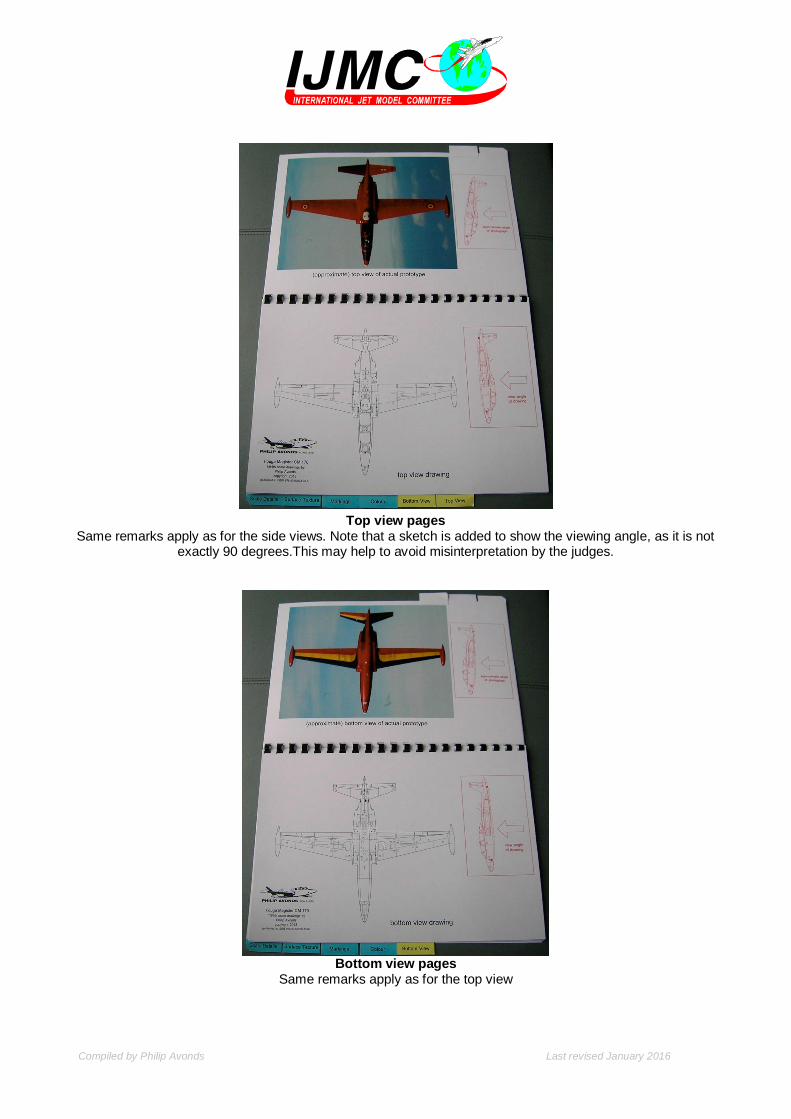
Compiled by Philip Avonds Last revised January 2016
Top view pagesSame remarks apply as for the side views. Note that a sketch is added to show the viewing angle, as it is not
exactly 90 degrees.This may help to avoid misinterpretation by the judges.
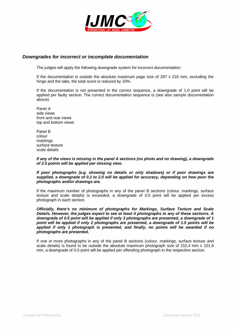
Bottom view pagesSame remarks apply as for the top view

Compiled by Philip Avonds Last revised January 2016
Now we proceed to the second major part of the documentation, the pagescorresponding to panel B: colour, markings, surface texture and scale details (bluetabs)General: the number of photographs is limited to 8 per topic (10 for scale details) and the size of thephotographs is limited to 150 x 100 mm. The US size of 6 x 4 inches is also acceptable which increases theabsolute size limit to 152,4 mm x 101,6 mm (the template attached reflects this absolute size limit). If thenumber and/or the size of photographs is exceeded, you will be downgraded. It is a good idea to usedrawings to help in identifying the location of colours, markings, surface texture or details.
Note: it is not allowed to combine any number of different photographs in one photograph (multiplephotographs in one print) in an attempt to show more different parts of the subject. It is your job to choosethe most representative parts or to capture different elements in one single shot. If photographs are found tobe combined, they will be counted as separate photographs counting towards the maximum number. Ifexceeded, you will be downgraded.
1. Colour: should be proved by as direct a method as is feasible for the subject modelled. Amaximum of 8 photographs of limited size and a maximum of 8 colour chips may be included
Colour pages
Colour photographs (8 maximum) can be used, colour profile drawings can be used, but the best way toprove the correct colours is with authenticated paint chips (8 maximum). In the sample, the original paint ofthe full size prototype was used to paint the model and a declaration of the demonstration pilot confirms this.You can also have the chips verified by a museum in which case a stamp is required on each chip. Tip: placethe chips adjacent to the edge of the page to allow the judges to lay them on the model for comparison.
It is important that you clearly indicate which colour goes where on the subject aircraft. You can separate thecolour documentation in primary and secondary colours if desired. Secondary colours are colours only visibleon markings or on sections with special paint jobs (like a tiger head on the fin etc.).
The photograph above shows the paint authenticity declaration on the top page while the bottom pageshows pictures of the location of the primary and secondary colours. Also included is a photograph showingthe gloss finish.
AuthenticityDeclaration
Colour Chips(8 max)
Photographsto prove other
colours(8 max)
Photograph toprove gloss
finish

Compiled by Philip Avonds Last revised January 2016
Authenticated (stamped) colour chips would further improve the value of this documentation.
2. Markings: A maximum of 8 photographs of limited size may be included (a minimum of 4 isrecommended, see “Downgrades” at the end of this document)
Markings pages
You have a maximum number of 8 photographs to show detailed shots of the markings of the prototype.
A drawing showing the location of some markings can be helpful if the markings are difficult to locate andwould further improve the quality of this documentation.
3. Surface Texture: A maximum of 8 photographs of limited size may be included (a minimum of 4 isrecommended, see “Downgrades” at the end of this document)
Surface texture pages

Compiled by Philip Avonds Last revised January 2016
You have a maximum number of 8 photographs to show detailed shots of the surface texture of theprototype. Different areas showing different styles of surface texture will generate more complexity points.
4. Scale Details: A maximum of 10 photographs of limited size may be included (a minimum of 4 isrecommended, see “Downgrades” at the end of this document)
Scale Detail pages
Choose details which are prominent. In this example, the airbrakes, the flaps, the main wheels, the scoops,the instrument panel, the periscope, the elevator counterweights and the nose landing gear are prominent,but ultimately, it is your choice. There is no need to document all details but if you can capture severaldifferent details in one shot, this could result in a better score for the complexity part of the topic. Anyway,remember you are limited to a maximum of 10 photographs. Here two drawings were added to clarify thelocation of some details.
Official text from the rulebook:
4.0.2 Scale Documentation
Models will be placed in a "ready box", prior to formal Static Judging, for preliminary checks to bemade. During formal Static Judging a Timekeeper will ensure compliance with Rule 4.0.3. To beeligible for static points the contestant must submit the following minimum documentation to thejudges (see format requirements under 4.0.2 (k)):
(a) Three identical copies of an accurate published 3-view (minimum, though all six views arerecommended) scale drawing of the full-size aeroplane having a minimum scale of 1/72, and amaximum scale of 1/24. Unpublished drawings by the contestant or other draughtsman are onlyacceptable if they are certified in writing as accurate in advance of the contest, by an authoritativesource (such as the respective National Scale Committee or equivalent), the builder of the originalaircraft, or other competent authority.

Compiled by Philip Avonds Last revised January 2016
(b) At least three differing photographs, or published printed reproductions, of the full-size aircraft,including at least one of the actual subject aircraft being modelled. At least one of these must showthe prototype aircraft on the ground to allow the landing gear assembly to be judged.
(c) For proof of colour, if one or more of the photographs in (b), of the actual subject modelled, is not incolour, then a published coloured drawing is acceptable, or a published printed description of thecolour scheme (for example those from specialist scale model publications). Alternatively,authenticated written description and/or authenticated colour chips are acceptable.
(d) Photographs must be considered to be more important than 3-views, and will take precedence overthree-view drawings for verifying scale outlines.
(e) If the judges suspect that the information supplied in the presented documentation has beenmanipulated, the Contest Director should be informed immediately by the spokesman for the staticjudges. The Contest Director will then decide how to proceed.
(f) If the contestant presents only partial or excessive documentation, the static score points will beawarded in proportion to the documentation supplied.
(g) If the contestant presents no documentation at all, the static judging cannot be performed, and thestatic score will be zero.
(h) In the event that there is conflicting evidence in the documentation presented, it is the responsibilityof the contestant, before judging commences, to indicate to the static judges which documents theyare to ignore.
(i) The complete documentation should be submitted in triplicate prior to the static judging. After thestatic judging is finished, one copy of the documentation will stay with the static judging panel untilthe end of the competition.
(j) Any tampering to the documentation can result in disqualification of the offending contestant.
(k) Documentation format: A4 size, landscape with hinge on long side (calendar format)
Scale Accuracy - side views: 1 side view drawing minimum (left and right hand side drawingspreferred), 1 photograph of each side minimum (*)
Scale Accuracy - front and rear view: 1 end view drawing minimum (front and rear view drawingspreferred), 1 photograph of front and 1 photograph of rear minimum (*)
Scale Accuracy - top and bottom view: 1 plan view drawing minimum (top and bottom view drawingspreferred), 1 photograph of top and 1 photograph of bottom minimum (*)
Colour: should be proved by as direct a method as is feasible for the subject modelled. A maximumof 8 photographs (**) and a maximum of 8 colour chips may be included
Markings: A maximum of 8 photographs (**) may be included
Surface Texture: A maximum of 8 photographs (**) may be included
Scale Details: A maximum of 10 photographs (**) may be included
(*) These photographs should show the full size aircraft as close as possible to the required view toallow the judges to do their work properly. This doesn’t mean these photographs should show aview at perfect right angles, as these are hard to find for some subjects. As long as they are close toright angles, they will be acceptable. The size should show the subject in a similar size as thedrawing.
(**) Maximum size 10 x 15 cm (4 x 6 inches)
Compiled by Philip Avonds Last revised January 2016
Downgrades for incorrect or incomplete documentation
The judges will apply the following downgrade system for incorrect documentation:
If the documentation is outside the absolute maximum page size of 297 x 216 mm, excluding thehinge and the tabs, the total score is reduced by 10%.
If the documentation is not presented in the correct sequence, a downgrade of 1.0 point will beapplied per faulty section. The correct documentation sequence is (see also sample documentationabove):
Panel Aside viewsfront and rear viewstop and bottom views
Panel Bcolourmarkingssurface texturescale details
If any of the views is missing in the panel A sections (no photo and no drawing), a downgradeof 2.5 points will be applied per missing view.
If poor photographs (e.g. showing no details or only shadows) or if poor drawings aresupplied, a downgrade of 0.1 to 2.0 will be applied for accuracy, depending on how poor thephotographs and/or drawings are.
If the maximum number of photographs in any of the panel B sections (colour, markings, surfacetexture and scale details) is exceeded, a downgrade of 0.5 point will be applied per excessphotograph in each section.
Officially, there’s no minimum of photographs for Markings, Surface Texture and ScaleDetails. However, the judges expect to see at least 4 photographs in any of these sections. Adowngrade of 0.5 point will be applied if only 3 photographs are presented, a downgrade of 1point will be applied if only 2 photographs are presented, a downgrade of 1.5 points will beapplied if only 1 photograph is presented, and finally, no points will be awarded if nophotographs are presented.
If one or more photographs in any of the panel B sections (colour, markings, surface texture andscale details) is found to be outside the absolute maximum photograph size of 152,4 mm x 101,6mm, a downgrade of 0.5 point will be applied per offending photograph in the respective section.

Compiled by Philip Avonds Last revised January 2016