ijmet 06 08_015
TRANSCRIPT

http://www.iaeme.com/IJMET/index.asp 156 [email protected]
International Journal of Mechanical Engineering and Technology (IJMET) Volume 6, Issue 8, Aug 2015, pp. 156-169, Article ID: IJMET_06_08_015 Available online at http://www.iaeme.com/IJMET/issues.asp?JTypeIJMET&VType=6&IType=8 ISSN Print: 0976-6340 and ISSN Online: 0976-6359 © IAEME Publication
________________________________________________________________________
SCS &GIS ENABLED PROJECT
MANAGEMENT SYSTEM FOR DEVELOPMENT AND IMPLEMENTATION
PHASE OF GAS DISTRIBUTION PROJECT
G. Dhamodaran
Department of Mechanical Engineering, School of Mechanical Engineering,
AMET University, Chennai
R. J. Golden Ranjith
Assistant Professor, Dept. of Mechanical Engineering,
Bharath University, Chennai, India
ABSTRACT
Background/Objectives: To investigate the usefulness of requirement of
‘Supervisory Control System for Gas Distribution Construction Project Management’.
Methods/Statistical analysis: Human Video interface model preparation and updating the live progress of the project to Update on the monitor installed in Central Project Room thru Arc GIS and other Pipeline modules
interlinking with GPS Technology.
Results/Findings: Can be implemented at construction projects of Gas
Distribution Project where there will be complex Network of pipelines and were geographically dispersed.
Conclusion/Application: “Supervisory Control System with GIS data for
development and implementation phase for Gas Distribution Construction Project Management” can be implemented.
Key words:
Human Video Interface Monitor- Large size monitor where the entire network of the Gas distribution circuit can be seen and required selection can
be made based on the requirement.
GIS -Geographical Information System – Integrated Tool/Application
having Geographical information’s which maps all data related to the pipeline network.

SCS & GIS Enabled Project Management System for Development and Implementation Phase of Gas Distribution Project
http://www.iaeme.com/IJMET/index.asp 157 [email protected]
Central Project Room- The Project Management room installed with the Monitor from where Progress is analysed and further front generation and
planning activities can be planned
Pipelines modules- The pipeline drawing software’s which produce the
alignment sheets
Pipeline alignment sheets- the drawing to the pipeline will all data like length, corridor, co-ordinates, fittings, cable details, turning points etc.
GPS Technology- The Radio frequency transfer technology thru which the progress can be updated.
SCS- Supervisory Control System- System with HMI enables to manage the Project having the facility of real-time updation of the data thru GPS technology.
Cite this Article: Dhamodaran, G. and Golden Ranjith, R. J. SCS & GIS enabled Project Management System for Development and Implementation
phase of Gas Distribution Project. International Journal of Mechanical Engineering and Technology, 6(8), 2015, pp. 151-164. http://www.iaeme.com/IJMET/issues.asp?JTypeIJMET&VType=6&IType=8
1. INTRODUCTION
The Pipeline network of the Gas distribution is a more complex network and construction of these kind of networks is a big task as many activities like Survey, Land acquisition, Right of way acquiring, Right of Use acquiring, excavation, laying,
testing, padding, cables installation, back filling, restoration etc..
There may be Trunk lines, lateral lines, Branch lines, final flow lines which will
be many numbers according to the distribution network, size of the pipelines will be varying with respect to the consumers located in one particular line or area. Also there will be many nodes, turning points to avoid any other facilities, with this kind of
complex networks; Project management becomes cumbersome exercise to have overall control over the Entire Project.
To overcome that Computer enabled methodology which will be having there preloaded data like pipeline routing, and other data. will have to be graphically represented and daily progress in each field are to be updated. Updation is easy in
present days as many internet or GPRS enabled messengers are available in the market like Whats-app, Telegram etc.. Constructing these complex pipeline facilities
for Gas Distribution Network are challenging tasks and generally this activity drives the project.
2. PRESENT METHOD AND ITS DIFFICULTIES
2.1. Present method being followed in the industry
In general, Every major portions either in terms of Trunk lines or in terms of area/Villages are being segregated and contracted with some agencies and based on
the progress reports and rare occasion meetings the progress is measured and there is no solid method available for front generation other than individuals’ capabilities.
Also conducting regular meeting with all the contractor by Project Manager is a
simple task and the person representing the individual area. Village/Trunk line also may not have th full knowledge about the happenings and further plans. To overcome

G. Dhamodaran and R. J. Golden Ranjith
http://www.iaeme.com/IJMET/index.asp 158 [email protected]
this one Project Management Cell with Supervisory Control System may be required and the updation s to be made simple.
2.2. Difficulties in present methods
As many of the areas were spread over many of the villages and many of the districts, only best way is to have the regular meetings with each of the one on regular intervals
at any office accessible by every one of the project. Here in this system everyone has to spend the time may be whole day oe even more than a day. Because to this, the meeting once in a week cannot be arranged and co-ordination becomes cumbersome
and hence delays the project
3. PROPOSED METHODOLOGY
In the Proposal submitter here, the Central Control Room has to be located with somewhere at the central location of the Gas distribution area. There in the Central Control Room, One big size with all required storages, servers, UPS, Work Station,
Preloaded software, Pre- loaded pipeline route/geographical data. HMI Screens etc.
A point to multipoint low band width radio connection will serve the purpose,
where the entire distribution network will get connected to the CCR. Where ever required some FOC network can also be implemented if required and volume of data transmission is high in nature. From the work location real-time updation by
respective field engineer will update the master data thru the radio network or GPRS enabled smart mobile phone where an application will have to be developed to
connect to Servers and HMI monitors. All networks and servers to be made accessible through LAN/ WAN / WEB / GPRS Network.
3.1. Database creation and Server Management
The following steps to be followed to create the master database. The Pipeline Data
management system based on Engineering and GIS to be developed by experienced specialist vendor. The entire field facilities and pipeline network to be mapped using Satellite images procured for the Field development area.
A master database of entire pipeline information will be created us ing GIS tools. The master database to include detailed facility layouts, pipeline alignment drawings,
facility location database, support facility information, ROU information, linked technical specifications, sparing schedule, maintenance schedule, and pigging schedule.
The Following minimum features will be provided in the Engineering Cum GIS based pipeline database management system:
Drawing release status
ROU application status
ROW application status
Revenue Survey details
Other lands acquisition status
Land over/ROU Compensation payment Status
Soil status
Excavation Status
Pipeline/Cable /other material arrival Status
Joints Welding Progress

SCS & GIS Enabled Project Management System for Development and Implementation Phase of Gas Distribution Project
http://www.iaeme.com/IJMET/index.asp 159 [email protected]
Lowering Status
Testing status and Reports
Backfilling Status
Pigging schedules
Customised report generation.
Accessibility to all relevant information / documents / drawings etc.
The proposed method is having majorly two parts called 1. Geographical Information System (GIS) and 2. Supervisory Control System (SCS)
3.1.1. Geographical Information System
This is Software supplied by various companies around the world which helps in viewing and managing the integrated pipeline network. This Spatially enabled GIS
Model manages the all pipeline attributes in centre line data with ensuring accuracy in data.
GIS system meets all the general and minimum requirement such as Database set
up, survey data uploading and reference, data exchange between various stakeholders, Alignment sheet Generations, Crossing drawings, Reference drawings, MTO Preparation etc. As this stores High Resolution Satellite imagery, data accuracy will
be attained.
The following Steps to be followed
Taking the High Resolution Satellite Imageries and updating in server
Verification of the Survey data
o Verification with respect to Spheroid/Ellipsoid Parameters o Verification with respect to topological and topographical parameters o Verification by superimposing Survey data with HRSIs
Uploading and updating the database server
Carrying out detailed Engineering works
With this the following minimum engineering deliverables can be extracted
Integrated Alignment Sheets
Crossing Drawings
Pipeline, Electrical and FOC standard drawings
Integrated MTOs for various disciplines
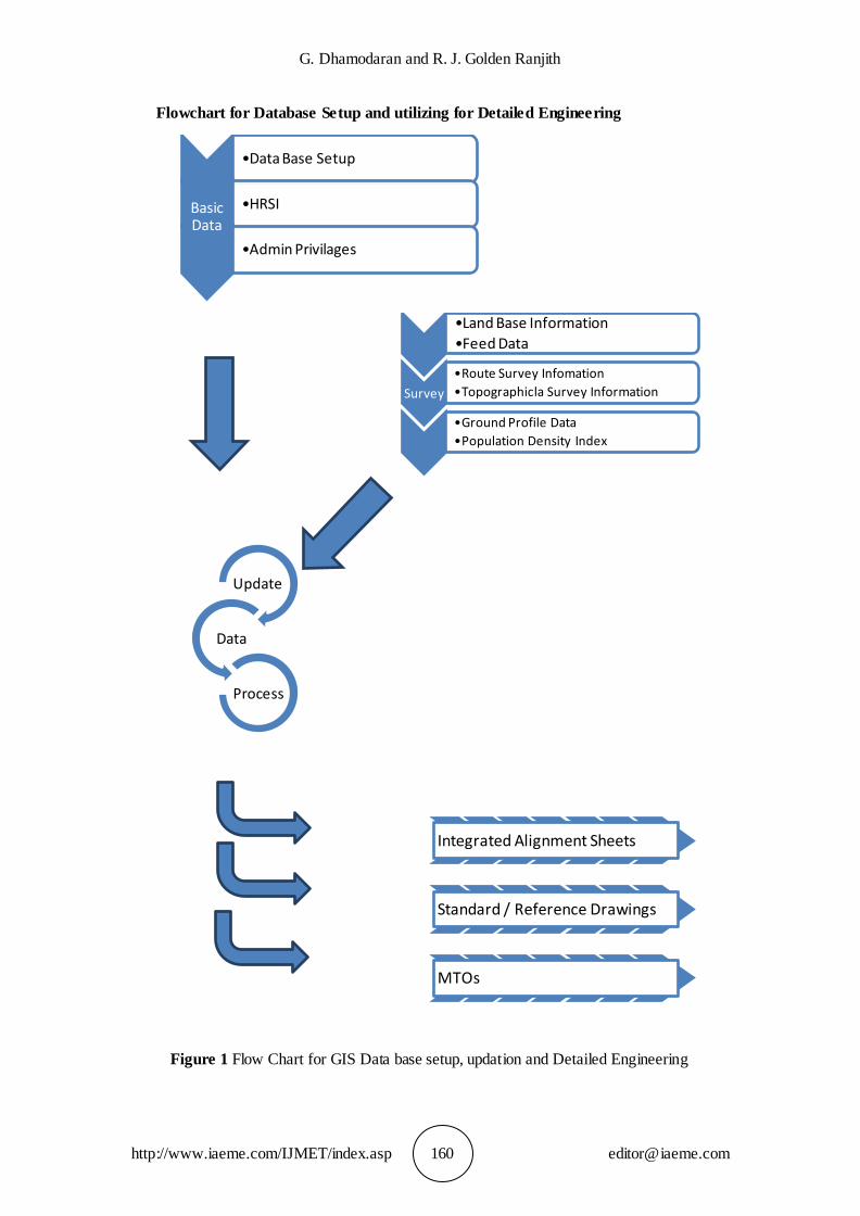
The following are the some of the important survey data which may be required to update the database
Land base information
Feed Data
Detailed Route Survey information
Topographical Survey information
Ground Profile data
Population Density Index
G. Dhamodaran and R. J. Golden Ranjith
http://www.iaeme.com/IJMET/index.asp 160 [email protected]
Flowchart for Database Setup and utilizing for Detailed Engineering
Figure 1 Flow Chart for GIS Data base setup, updation and Detailed Engineering
•Data Base Setup
Basic Data
•HRSI
•Admin Privilages
•Land Base Information
•Feed Data
Survey
•Route Survey Infomation
•Topographicla Survey Information
•Ground Profile Data
•Population Density Index
Update
Data
Process
Integrated Alignment Sheets
Standard / Reference Drawings
MTOs

SCS & GIS Enabled Project Management System for Development and Implementation Phase of Gas Distribution Project
http://www.iaeme.com/IJMET/index.asp 161 [email protected]
Some of the major Advantages of using Geographical Information System
Efforts required to manage records can be minimised
Efforts require to communicate with increased noumbers of stake holders can be minimised
Multiple data editors at one time can be increased with respect to size of the Project
Ease of Producing the Reports
Ease of Producing Engineering Deliverables
Visualisation by viewing the status in Web browser
Integrated link between Construction Contractor, Owner, Project Manager, Financing institute, Surveyors, engineers, Inspectors, Detail engineering Contractor, ROU Agents, Environmental Team, CSR Team etc.
Ease maintenance of E-log book
Viewing and Referring Survey shots whenever required
Permissions Status
Ease MIS Reporting
Crossing and legal permission Status
Accuracy in Data
Integrity in data
Efficient Project Management
Developing various Databases
Production of various Auto Cad Drawings
Linking Graphics to tables an d databases
Editing As built drawings
Tracing of Joints and status reporting
Uniqueness in data management
Aligning all project managers in one approach
Ease interface with SQL Servers
Ease in exporting graphics in required format
Generations of notification and alerts on daily updates and pending works
3.1.2. Supervisory Control System
The Central Control Room will be manned 24/7 and monitors the field parameters and
equipment status & alarms. The Control Room Operators will be responsible for alerting the Filed Construction team for any Follow up actions and control actions to
be taken at any of the field sites visa viz. Trunk lines, Branch lines, Lateral Lines, Field Lines or any other Permanent facilities oft the Project
This control Room will be Equipped with the large Video cum HMI Monitor
where the entire Pipeline network will be visually seen and the required portions can be enlarged and seen. With the help of any suitable application thru the GPS
frequency Signal site construction progress will be updated in the master data which will be of real-time updation.
Network system required to transmit the data could be either LAN/WIFI/Wireless
technology or any other thing. The follow up actions can be automatically or manually sent to the required portion or the project manager.
G. Dhamodaran and R. J. Golden Ranjith
http://www.iaeme.com/IJMET/index.asp 162 [email protected]
Remote Terminal Units(RTU) can be installed and important nodal points thru which the data can be communicated to the th central control Room. These RTUs will
be collecting data from the Various facilities and pipeline segments and transfer them to the Central Control Room.
The instrumentation & automation data from the Well will require low bandwidth; data polling will be on real-time basis. A point to multi point microwave radio networks will meet the requirement. There may be other low band width requirements
for IT voice network and for Security Automation. These can also be connected through the same Radio network
3.2. Various WBS and Activities to get covered
With the implementation of this SCS the following WBS may be getting covered along with applicable Activities
Engineering-
Detail Engineering Status,
MTOs,
Alignment Sheet Revision Status,
Schedule of releasing the other documents related to the particular section or part of the pipeline or facilities.
Procurement-
MR Status,
RFQ Status,
Material delivery status,
Material shifting status to erection location
Legal-
Permission Status,
Land Acquisition Status,
Crossing Details,
ROU Application Status,
ROW Status,
Compensation Status,
Local agitation details
Construction-
Excavation,
Grading
Bedding,
Stringing,
Joints welding,
Lowering,
Testing,
Back filling,
Restoration

SCS & GIS Enabled Project Management System for Development and Implementation Phase of Gas Distribution Project
http://www.iaeme.com/IJMET/index.asp 163 [email protected]
Other these, there are many other options can also be inducted in the Engineering-Cum-GIS based construction data base.
3.3. Options to be made available in menu
With the implementation of this SCS the following WBS may be getting covered along with applicable Activities.
The following table shows the list of options that may be required as a minimum to continue the construction
3.3.1. Engineering Phase
Table 1 Various Menu options required during Engineering Phase
Phase Location Entity Activity Progress Time
line Document
Quantity
Status
Level 1 Level 2 Level 3 Level 4 Level 5 Sub
Level-1 Sub level-
2 Sub
level-3
Engineering
Trunk Line/
Lateral line/
Branch line/ Flow
Line/ From
Chainage/ To
Chainage
Alignment sheet
Preparation
Started Target to
Start View
Procurement
Village/ Survey
Number/ Land
Owner
MTO Draft
Release In
progress Target to
Finish Download
Legal
other Engineerin
g Deliverable
approval Complete
d Target to Release
Retrive
Construction
Release Approved
Extract
Final Release
Sent for Approval
Upload
Revised
Comment
Released
Menu such as status of the all deliverables, their time line data can be fed. Also
the quantity status also can be included either in terms of numbers or in terms of percentages. In order to track the engineering deliverables the options like comment,
upload etc can now be included.
G. Dhamodaran and R. J. Golden Ranjith
http://www.iaeme.com/IJMET/index.asp 164 [email protected]
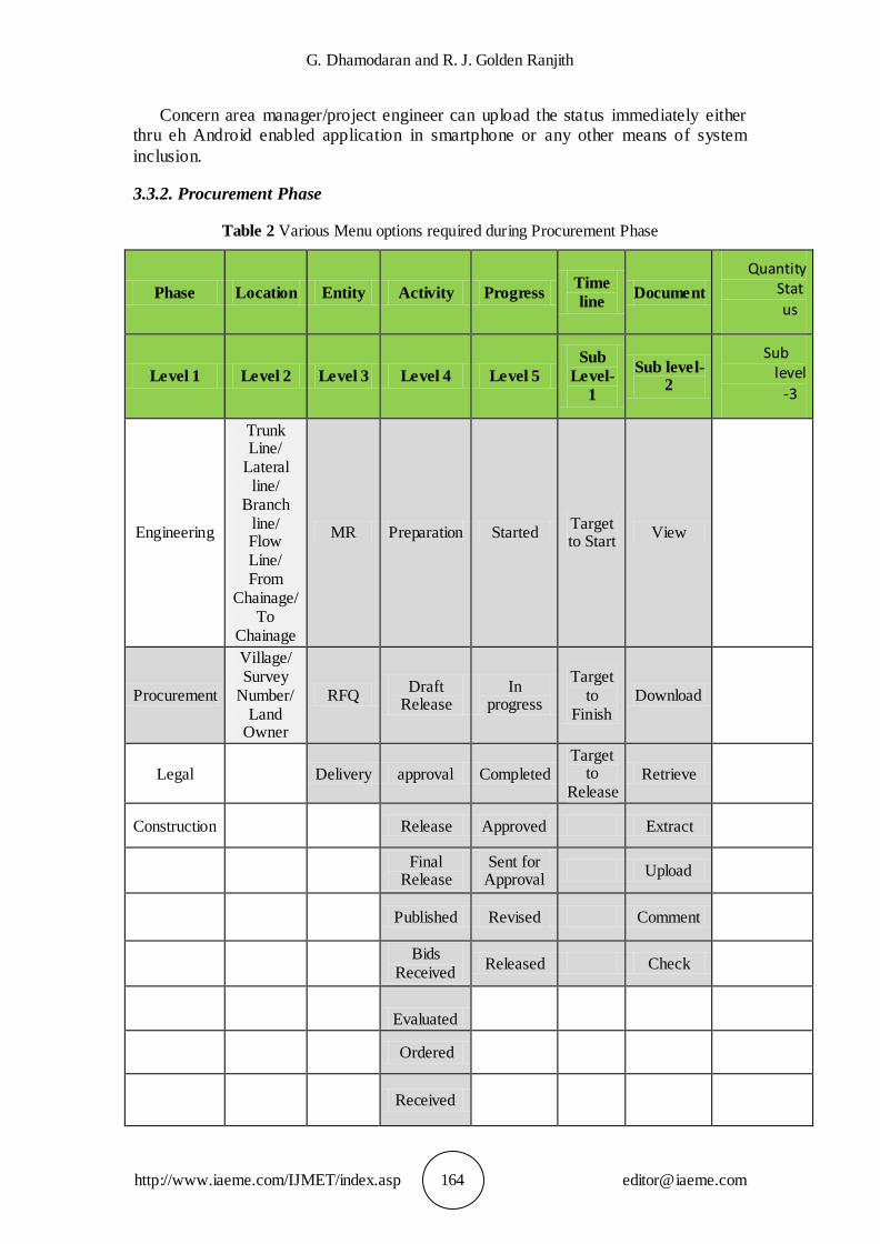
Concern area manager/project engineer can upload the status immediately either thru eh Android enabled application in smartphone or any other means of system
inclusion.
3.3.2. Procurement Phase
Table 2 Various Menu options required during Procurement Phase
Phase Location Entity Activity Progress Time
line Document
Quantity Stat
us
Level 1 Level 2 Level 3 Level 4 Level 5
Sub
Level-
1
Sub level-2
Sub level
-3
Engineering
Trunk Line/
Lateral line/
Branch line/ Flow Line/ From
Chainage/ To
Chainage
MR Preparation Started Target to Start
View
Procurement
Village/ Survey
Number/ Land
Owner
RFQ Draft
Release In
progress
Target to
Finish Download
Legal Delivery approval Completed Target
to Release
Retrieve
Construction Release Approved Extract
Final
Release Sent for
Approval Upload
Published Revised Comment
Bids
Received Released Check
Evaluated
Ordered
Received

SCS & GIS Enabled Project Management System for Development and Implementation Phase of Gas Distribution Project
http://www.iaeme.com/IJMET/index.asp 165 [email protected]
Procurement documents like Material Requisition, RFQ, Material Delivery can be tracked and status can be retrieved by the relevance users. The Procurement team to
update the status as and when happen in real time basis.
The Approval cycle of time and Technical Bid evaluation details and Technical
Recommendation details can also be included if required.
3.3.3. Legal Phase
Table 3 Various Menu options required during Legal Phase
Phase Location Entity Activity Progress Time line
Document Quantity Status
Level 1 Level 2 Level 3 Level 4 Level 5
Sub Level-
1
Sub level-
2
Sub
level-3
Engineering
Trunk Line/ Lateral line/ Branch line/ Flow Line/
From Chainage/ To
Chainage
Permission Preparati
on Started
Target to
Start View
Procurement
Village/ Survey
Number/ Land Owner
Crossing Draft
Release In
progress
Target to
Finish Download
Legal
LAQ approval Complete
d
Target to
Release
Retrieve
Construction
ROU Release Approved
Extract
ROW
Final Release
Sent for Approval
Upload
Agitation
Submitted
Revised
Comment
Tracked Released
Check
Corrected Paid
Received DD Sent
Fee Payment
Various legal issues like permissions from various boards and departments of Government bodies can be tracked in this SCS System. Right of Use and Right of
Way related progress etc can be traced in this. Also the Team who is co ordination with Legal departments to update the relevant documents on regular intervels.
G. Dhamodaran and R. J. Golden Ranjith
http://www.iaeme.com/IJMET/index.asp 166 [email protected]
Payments status to various applications can also be tracked with this and the local agitations and related FIRS can also be tracked and accordingly further front can be
generated.
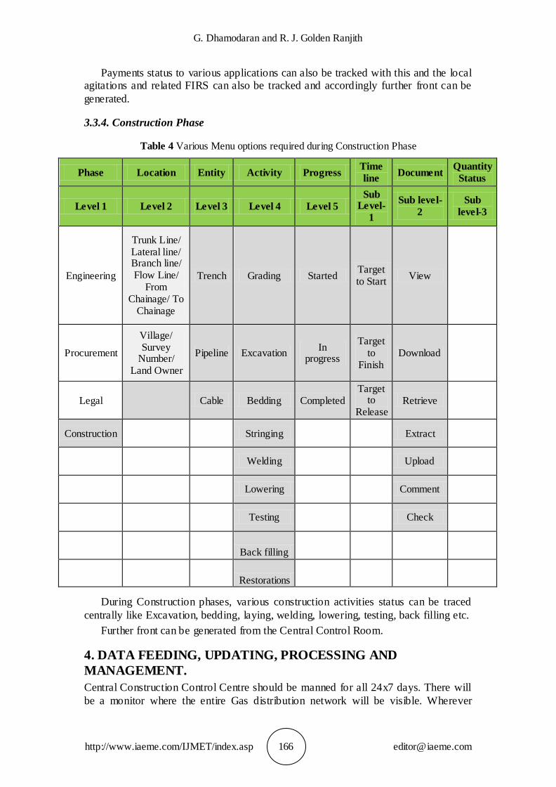
3.3.4. Construction Phase
Table 4 Various Menu options required during Construction Phase
Phase Location Entity Activity Progress Time
line Document
Quantity
Status
Level 1 Level 2 Level 3 Level 4 Level 5
Sub Level-
1
Sub level-
2
Sub
level-3
Engineering
Trunk Line/ Lateral line/ Branch line/ Flow Line/
From Chainage/ To
Chainage
Trench Grading Started Target to Start
View
Procurement
Village/ Survey
Number/ Land Owner
Pipeline Excavation In
progress
Target to
Finish Download
Legal
Cable Bedding Completed Target
to Release
Retrieve
Construction
Stringing
Extract
Welding
Upload
Lowering
Comment
Testing
Check
Back filling
Restorations
During Construction phases, various construction activities status can be traced
centrally like Excavation, bedding, laying, welding, lowering, testing, back filling etc.
Further front can be generated from the Central Control Room.
4. DATA FEEDING, UPDATING, PROCESSING AND
MANAGEMENT.
Central Construction Control Centre should be manned for all 24x7 days. There will
be a monitor where the entire Gas distribution network will be visible. Wherever
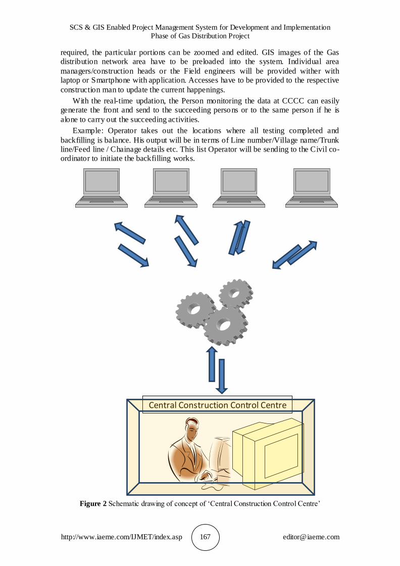
SCS & GIS Enabled Project Management System for Development and Implementation Phase of Gas Distribution Project
http://www.iaeme.com/IJMET/index.asp 167 [email protected]
required, the particular portions can be zoomed and edited. GIS images of the Gas distribution network area have to be preloaded into the system. Individual area
managers/construction heads or the Field engineers will be provided wither with laptop or Smartphone with application. Accesses have to be provided to the respective
construction man to update the current happenings.
With the real-time updation, the Person monitoring the data at CCCC can easily generate the front and send to the succeeding persons or to the same person if he is
alone to carry out the succeeding activities.
Example: Operator takes out the locations where all testing completed and
backfilling is balance. His output will be in terms of Line number/Village name/Trunk line/Feed line / Chainage details etc. This list Operator will be sending to the Civil co-ordinator to initiate the backfilling works.
Figure 2 Schematic drawing of concept of ‘Central Construction Control Centre’
Central Construction Control Centre

G. Dhamodaran and R. J. Golden Ranjith
http://www.iaeme.com/IJMET/index.asp 168 [email protected]
5. RESULTS
This kind id system is used in operation phase for many projects as “Supervisory
Control System and Data Acquisition”. Our Aim is to extend that kind of Central project Control Concepts which will increase the efficiency of the Project
management.
6. DISCUSSION
6.1. Advantages of using this system
This system has more advantages like,
a. Efficient Project management b. Better revision management in drawings and documents c. Complete reliability on the work progress and front d. Accurate reports e. Provides clear guidelines for planning, and forecasting f. Provides access to multiple users so that many people can work in same time g. Tracing facility of materials, reports, documents history etc. h. Helps in generating many data bases. i. Controls Duplication works j. Continues expedition from the Site team k. Single Point Co-ordination system which minimise the error. l. Completely provides real time tracking of the progress m. Generates Front for almost all disciplines included in the scope n. Minimal investment and no major operational cost o. Less Manpower requirement
7. CONCLUSION
As this reduces lot of man-hour wastages and time this method can be encouraged for many of the Pipeline projects like Gas Distribution Projects.
ACKNOWLEDGEMENTS
Informally many other forms the same concept is being used partially in many of the
Gas distribution Projects. With little improvement and value addition will yield good results in terms of the efficient Project Management.
REFERENCES
[1] Al-Momani, A. H. Construction delay: A quantitative analysis. International Journal of Project Management, 18(1), 2000.
[2] Ammar, M. A. and Mohieldin, Y. A. Resource constrained project scheduling using simulation. Construction Management and Economics, 2002.
[3] Assaf, S. A. and Al-Hejji, S. Causes of delay in large construction projects. International Journal of Project Management, 2006.
[4] Chan, A. P. C., Scott, D. and Chan, A. P. L. Factors affecting the success of a construction project. Journal of Construction Engineering and Management, 2004.
[5] Graham, G. E., Maxwell, D. A. and Vallone, A. How to Optimize Gas Pipeline Networks. Pipeline Industry, June, 1971. 41–43.
[6] Martch, H. B. and N. J. McCall. Optimization of the Design and Operation of Natural Gas Pipeline Systems. Paper No. SPE 4006, Society of Petroleum Engineers of AIME, 1972.

SCS & GIS Enabled Project Management System for Development and Implementation Phase of Gas Distribution Project
http://www.iaeme.com/IJMET/index.asp 169 [email protected]
[7] Flanigan, O. Constrained Derivatives in Natural Gas Pipeline System Optimization. Journal of Petroleum Technology, May, 1972, pp. 549.
[8] Mah, R. S. H. and Schacham, M. Pipeline Network Design and Synthesis. Advances in Chemical Engineering, 10, 1978.
[9] Cheesman, A. P. How to Optimize Gas Pipeline Design by Computer. Oil and Gas Journal, 69(51), December 20, 1971, pp. 64.
[10] Cheesman, A. P. Understanding Origin of Pressure is a Key to Better Well Planning. Oil and Gas Journal, 69(46), November 15, 1971, pp. 146.
[11] Edgar, T. F., Himmelblau, D. M. and Bickel, T. C. Optimal Design of Gas Transmission Network. Society of Petroleum Engineering Journal, 30, 1978, pp. 96.
[12] Hasan, H. S. and Dr. Ramesh Babu, P. SCS Analysis and Control of Mobile Robot for Pipe Line Inspection. International Journal of Mechanical Engineering and Technology, 4(5), 2013, pp. 01–09.
[13] Olorunniwo, F. O. A Methodology for Optimal Design and Capacity Expansion planning of Natural Gas Transmission Networks. Ph.D Dissertation, The University of Texas Austin, May, 1981
[14] Wong, P. J. and Larson, R. E. Optimization of natural gas pipeline systems via dynamic programming. IEEE Trans. Auto. Control, AC-13(5), October 1968, pp. 475–481.
[15] Harris, R. B. and Ioannou, P. G. Scheduling projects with repeating activities. Journal of Construction Engineering and Management, 1998.