ilc detector r&d - deutschlands größtes ... · pdf file22nd january 2008 ilc...
TRANSCRIPT

22nd January 2008 ILC Detector R&D Chris Damerell 1
ILC Detector R&Das seen by the Detector R&D Panel
(a Panel of the World-Wide Study Organising Committee)
(Jean-Claude Brient, Chris Damerell, Ray Frey, Dean Karlen, Wolfgang Lohmann, Hwanbae Park, Yasuhiro Sugimoto,
Tohru Takeshita, Harry Weerts)
Chris Damerell (RAL)

22nd January 2008 ILC Detector R&D Chris Damerell 2
What is ILC?

22nd January 2008 ILC Detector R&D Chris Damerell 3
• SC linacs 31.5 MV/m for 11 km delivering 500 GeV collision energy (gradient is a major R&D topic)
• Undulator-based positron source (current baseline) (major R&D topic)
• Electrons and positrons have just one damping ring each (issues of electron cloud permitting – major R&D topic)
• Single IR, 14 mrad crossing angle
• 2 detectors operating in push-pull (current baseline, could change) [all the many benefits of two detectors, other than a luminosity advantage]
• Bunch trains at 200 ms intervals, train duration ~1 ms
• Machine must be upgradeable to 1 TeV
• 4-volume Reference Design Report plus companion document was published October 2007 – but design will continue to evolve in light of ongoing R&D

22nd January 2008 ILC Detector R&D Chris Damerell 4
337 ns
0.2 s
≈1 ms
Bunch structure at the ILC
2820 bunch crossings
• Detector options:– Single bunch timing– Time-slicing of train (eg at 50 µs intervals, 20 slices)– Integrate signals through train, with relaxed readout during the inter-train period
• No ‘right answer’, despite statement of one collaboration that they will ‘time-stamp everything’
• Power advantage in partial or complete time integration – fine sensor granularity can compensate for pileup from multiple bunch crossings
• Lower power enables reduced material budget – desirable for physics
• Successful history of exploiting granularity/time resolution tradeoffs in ACCMOR and SLD collaborations
• Contrast LHC, where single bunch timing is mandatory

22nd January 2008 ILC Detector R&D Chris Damerell 5
The four detector concepts
• LDC and GLD now merging into ILD for the LOI and EDR phase • Work will lead to ‘light’ or ‘demonstrator’ or ‘practice’ EDRs in 2010 (or 2012?)• Detectors to be built depend on R&D that cannot be completed before ~2012

22nd January 2008 ILC Detector R&D Chris Damerell 6
Do we need R&D for ILC detectors?
• “After all the R&D for LHC detectors (operating in a more hostile environment), this should be more than enough”
• WRONG!
• To satisfy the very challenging ILC physics goals, we need detectors that nobody knows how to build
• What is easy, relative to LHC:– Instantaneous particle fluxes– Required radiation tolerance
• What is difficult, relative to LHC:– The need for extraordinary jet energy resolution and vertexing performance
• Special opportunities, relative to LHC:– Observe complex physics processes almost at the Feynman diagram level
} 1/R2 to inferno at LHC collision point

22nd January 2008 ILC Detector R&D Chris Damerell 7
e+ e- t tbar
At first sight, a confusing spray of particles …

22nd January 2008 ILC Detector R&D Chris Damerell 8
Mark Thompson
The miracle of PFA (or equivalent jet energy resolution) reveals the flow of energy from the quarks of the primary interaction
However, this is still not enough information for full physics analysis ..

22nd January 2008 ILC Detector R&D Chris Damerell 9
• Precision measurement of jet energies is not enough
• Which are b-jets, charm-jets or light quark jets?
• For the heavy quark jets, which are quarks and which anti-quarks?
• Answering these questions is the job of the vertex detector, by observing the particles which emerge from decay of B and D hadrons, with lifetimes ~10-12 s
• Achieving the required performance is the task of the most expensive ILC detector R&D topic
ILC vertex detector – a vital component

22nd January 2008 ILC Detector R&D Chris Damerell 10
e-L
96% b-jets
4% bbar jets
(e+R)
96% bbar-jets
4% b jets
Quark charge determination from ‘vertex charge’
In this event, total charge in decay chain for backward jet resolves the
forward-backward ambiguity – pioneered in, and unique to, SLD

22nd January 2008 ILC Detector R&D Chris Damerell 11
ILC vs LHC vertex detector parameters
200.1% X02 % X0Layer thickness
15~3 µm~45 µmTracking precision
0.005~100 krad~20 MradsRadiation resistance
0.0005~50 µs25 nsSensitive time window
ILC/LHC performance
ILCLHCParameter
Which is better – a Sherman tank or a Ferrari?
Each has its uses …

22nd January 2008 ILC Detector R&D Chris Damerell 12
A physics example – e+ e- b bbar
• Need highly polarised electron beams (longitudinal polarisation)
• Need extremely clean b-tag to distinguish from other q-qbar processes
• Need vertex charge to distinguish between b and bbar jets, otherwise see folded distns
• These capabilities were pioneered at SLC/SLD, and are unique to the LC technology
• Reward will be sensitivity to new physics via ‘oblique corrections’, where direct observation is beyond the reach of both ILC and LHC
• Another important example – if LHC finds the Higgs, is it the SM Higgs, SUSY Higgs, or what? Precision measurements of branching ratios by ILC will be needed to decide
Joanne Hewett, Sabine Riemann

22nd January 2008 ILC Detector R&D Chris Damerell 13
• Panel was formed at LCWS March, 2005 (Stanford U, same time as the GDE))– Original task: gather information on the work going on, and write a report– WWS-OC was cautious – detector people ‘fiercely independent’
• Dan Peterson organised the website, https://wiki.lepp.cornell.edu/ilc/bin/view/Public/WWS/
• After some effort we managed to get reports from all the major groups and most of the minor ones – one page per project
• We produced a document ‘Status Report and Urgent Requirements for Funding’, 6 Jan 2006, available from above website
• This indicated ~ $33M p.a. established, ~ $55M p.a. required for timely completion of the urgent R&D programme
• ‘urgent needs’ or ‘unrestrained desires’? Our next job was to find out …
Our first year …

22nd January 2008 ILC Detector R&D Chris Damerell 14
Totals over 3-5 yrs, to completion of R&D
1163 man-yrs established, 1873 man-yrs required
Equipment cost ~ 15% of manpower, so focus on the RH plots

22nd January 2008 ILC Detector R&D Chris Damerell 15
Our report, distributed to FALC and specific funding agencies, helped to produce some uplift in support in Japan and USA during 2006/7

22nd January 2008 ILC Detector R&D Chris Damerell 16
• All groups are of course subject to national peer review, and in many cases there are effective regional review procedures (eg the DESY PRC)
• Do these suffice? There were some concerns in our report about missing items (notably forward tracking, and possibly Cerenkov-based particle ID)
• Meanwhile, the ILC accelerator community, through the RDB, organised world-wide task forces, designed to optimise their R&D activities
• Partly in response, the WWS-OC, supported by the GDE-EC, decided to initiate world-wide detector R&D reviews (finally agreed at ECFA workshop, Valencia October 2006)
• Shortcomings in detector design at LEP and SLD did reduce the physics output – maybe dramatically (Bs mixing, possible Higgs) Were any of these avoidable, other than with hindsight?
• With our world-wide R&D network, we can aim for unprecedented detector performance at ILC, matched to the complex physics challenges, provided we maintain a coherent and flexible programme

22nd January 2008 ILC Detector R&D Chris Damerell 17
Purpose of the reviews
• Improved communication leading to enhanced R&D programmes
• Get representatives of all R&D groups together for face-to-face discussions
• Engage world-leading consultants from outside the ILC community, who would surely provide new insights – they did!
• The self-organising abilities of our community should lead to refinements in the world-wide R&D programme
• Ideally, the committee report would do little more than document these mutually agreed changes
• “If you don’t have buy-in, you can’t effect change.”
• The reality proved a bit more complicated, but also possibly more productive than anticipated, due mainly to fresh contributions from those consultants

22nd January 2008 ILC Detector R&D Chris Damerell 18
• Included in regional workshops:– Beijing (Feb ’07) Tracking– DESY (LCWS June ’07) Calorimetry
– Fermilab (Oct ’07) Vertexing– Sendai (March ‘08) PID, muon trkg, solenoid, beam diagnostics, DAQ
[deferred**]– Take special care to cover topics in the cracks between our review areas,
such as ‘fliers’
• ** In view of other developments (formation of LOI groups, Detector Directorate and IDAG), we will take a break at Sendai and reflect on what has been learned from the three reviews of 2007
Overview of the reviews

22nd January 2008 ILC Detector R&D Chris Damerell 19

22nd January 2008 ILC Detector R&D Chris Damerell 20
Tracking Review Committee
• Panel members: Chris Damerell (chair), Dean Karlen, Wolfgang Lohmann, Hwanbae Park, Harry Weerts
• External consultants: Peter Braun-Munzinger, Ioanis Giomataris,
Hideki Hamagaki, Hartmut Sadrozinski, Fabio Sauli, Helmuth Spieler, Mike Tyndel, Yoshinobu Unno
• Regional representatives: Jim Brau, Junji Haba, Bing Zhou
• RDB chair: Bill Willis
• Local tracking experts: Chen Yuanbo, Ouyang Chun
• Admin support: Naomi Nagahashi, Maura Barone, Maxine Hronek,Xu Tongzhou

22nd January 2008 ILC Detector R&D Chris Damerell 21
• We saw our responsibility as working with the R&D collaborations to ensure that the feasibility of their critical goals can be demonstrated by about 2012
• This means (for tracking) that the community can be confident that the option they choose will satisfy the challenging physics needs
• We reviewed the LCTPC, CLUCOU, SiLC and SiD tracking R&D
collaborations
• We were extremely impressed by the great progress made by all these groups, in some cases with very limited resources
• However, we concluded that we are currently far from the goals, for all tracking options
Overview of the review

22nd January 2008 ILC Detector R&D Chris Damerell 22
Structure of the review
• Collaboration reports provided an overview of the projects through to ‘completion’ of R&D, meaning ‘ready for engineering design and construction’
• Open session presentations provided summaries of status and plans
• Closed session was used to clarify technical and organisational issues, and to discuss their needs for additional resources
• Closeout session: Committee informed collaborations of our draft recommendations, and tried (with partial success) to obtain their verbal agreement
• Report was released by the WWS-OC chairs on 22nd May, along with appendices from 2 of the 4 the R&D collaborations, in which they discuss areas of disagreement. See the Detector R&D Panel Wiki page http://www.linearcollider.org/wiki/doku.php?id=drdp:drdp_home

22nd January 2008 ILC Detector R&D Chris Damerell 23
• Building a tracking system with excellent performance for θp >7 degrees will be challenging. Feasibility is not yet demonstrated
• Why not simply move on to the ‘engineering designs’ of these tracking systems and study their performance with Geant 4?
• There is a risk that such designs would be too optimistic. Forward tracking has generally performed badly. We all know the solution (drastic reduction in material budget) but can this be achieved in practice? The committee concluded that this crucial question, on which a great deal of ILC physics depends, could not be answered only by adventurous designs
• We became convinced of the need to construct large prototypes (~1 m diameter), and operate them under ILC-like beam conditions in a 3-5 T field, to establish what performance will be achievable at ILC, both for central and forward tracking
• Until such tests are completed successfully, we do not consider that any of the three options proposed (all-silicon, TPC-plus-silicon, or drift-chamber-plus-silicon) could be considered ready for selection as an ILC tracking system [a unanimous recommendation of the committee, but not every collaboration agrees with this; maybe we are wrong]
• As well, our experts made numerous detailed suggestions (see the report) which we hope proved useful to the groups in optimising their R&D programmes
Main technical recommendations

22nd January 2008 ILC Detector R&D Chris Damerell 24

22nd January 2008 ILC Detector R&D Chris Damerell 25
A possible split-coil solenoid
Estimated cost ~$800k(Elwyn Baynham industrial contacts)

22nd January 2008 ILC Detector R&D Chris Damerell 26
• We were encouraged by the success of the task-forces that provided world-wide coordination of the ILC accelerator R&D, to wonder about the utility of a Tracking Coordination Group (TCG)
• NOT some external body (like the Review Committee) but one or two ‘insiders’ from each R&D group, plus perhaps cross-members from the Vertexing CG and the Test-beam CG
• They would be free to work out their own charge, within some very general guidelines, possibly as follows:
• Negotiate for suitable funding for infrastructure (comprising a custom-designed test beam, solenoid, etc,), coordinate the use of these facilities, and ensure objective evaluation and presentation of the test results
• An important by-product would be that these individuals would rapidly become THE experts on every aspect of the world-wide tracking R&D, and hence become a valuable source of wisdom for the community
• The choice of technologies will as usual be made by experiment collaborations in conjunction with the IDAG, but the TCG would aim to inform those decisions in the most objective way possible
Organisational considerations

22nd January 2008 ILC Detector R&D Chris Damerell 27
• Spend on ILC detector R&D is considered by the community to be seriously inadequate (see R&D Panel Report of January 2006). The first of the R&D reviews (on tracking) confirmed the urgent need for some increase in resources
• Our committee echoed the comment of one of the collaborations: ‘Ultimately, the greatest R&D risk is that insufficient resources will be directed towards achieving the goals of this plan’
• We hope that the ILC Detector Directorate, working with the funding agencies and lab directors, will help to secure the needed resources
• We should be very careful not to weaken the R&D groups (in order to support the LOIs and Engineering Designs) just when they are most in need of support. The ILC physics programme depends on R&D which cannot possibly be completed before about 2012
Resources

22nd January 2008 ILC Detector R&D Chris Damerell 28
• The most serious concern of the committee was the material budget, particularly how this would degrade the forward tracking:
– For TPC tracker, can the endplate thickness really be reduced to ‘well below 0.3 X0‘, say to 0.1X0? Our outside consultants were extremely doubtful
– The drift chamber could be thinner, but will it provide robust track finding for high energy jets? Detailed simulations urgently needed, which requires increased manpower
– Everyone agrees that the ‘momenter’ concept is flawed. For a Si strip tracker, will 5 single-sided layers (barrel or disks) suffice, or will there be serious pattern recognition problems for high energy jets with long-lived Bs, necessitating more layers and hence worse problems with material budget and photon conversions in those jets, degrading also the ECAL-initiated tracking?
• Ongoing discussions with our imaginative committee members led to a new suggestion – a silicon pixel tracker (SPT) which could provide excellent pattern recognition with very little material over the full solid angle.
• A preliminary study of this idea by Konstantin Stefanov of RAL looks promising. His presentations to the SiD and SiLC collaborations have led to some simulations beginning, with results eagerly awaited
A new idea – Silicon Pixel Tracker

22nd January 2008 ILC Detector R&D Chris Damerell 29
• A pixel tracker, being entirely free of ghost hits, has a proven track record, extremely high pattern recognition efficiency compared to microstrips in high multiplicity jet-like events (ACCMOR Collaboration, mid-1980s)

22nd January 2008 ILC Detector R&D Chris Damerell 30
• Backgrounds, both in the barrel and fwd disks, are so benign that signal integration through the train, with readout between trains, is entirely acceptable (results of study by Takashi Maruyama of SLAC)
– Converted photons from the pair background (mostly bremsstrahlung photons from the vertex detector) have a max hit density of 2.0/cm2/train
– Charged particles mostly from 2-photon events have a max hit density of 1.0/cm2/train
– Assuming 50 µm square pixels, chosen to give ~15 µm precision with binary readout, occupancies are below 0.005%

22nd January 2008 ILC Detector R&D Chris Damerell 31
Barrel and Forward trackers, total area = 70.3 m2
With 50 μm × 50 μm pixels – 28.1 Gpix system Low mass support, gas cooling If each chip is 8 cm × 8 cm (2.6 Mpix): 11,000 sensors is total

22nd January 2008 ILC Detector R&D Chris Damerell 32

22nd January 2008 ILC Detector R&D Chris Damerell 33
• Two low-mass technology options identified, charge-coupled devices (CCDs) or monolithic active pixel sensors (MAPS)
• CCDs may be preferred due to high yield for large area devices and industrial gear-up for mosaics of many sq metres (e2V, Hamamatsu, DALSA)
• Spatial resolution of ~10 µm in both rφ and z expected, from devices with 50 µm thick sensitive layer (Nick Sinev is now simulating this)
• Rough cost estimate ~$40M, about 20 times greater than microstrips, but a bargain if they solve a significant pattern recognition problem over all solid angles, with much reduced material budget (to be determined from simulations by SiLC and SiD colleagues)
• Layer thickness ~0.2%X0 (200 µm thick CCD, 50 µm active) ~0.2%X0 Cu-kapton ~0.45%X0 SiC foam ladder (ladders linked along length to form
barrels or disks (~0.85%X0 per layer total, a bargain for unique space points)
• Time slicing/bunch stamping possible with MAPS, but power increases greatly
• All tracks will be time-tagged by their signals in the hermetic ECAL

22nd January 2008 ILC Detector R&D Chris Damerell 34
Cutout view without endcaps

22nd January 2008 ILC Detector R&D Chris Damerell 35
substrate (p+)
n buried channel
RG OD RSELTransfer Gate
shielding p+
Collection gate(s)
Photogate transfer with Buried Channel storage
50 μm
V1 < V2 < V3 < V4
Charge collection for large pixels, using ‘potential funnel’
TG
Charge transfer allows correlated double sampling and low
noise (10 e- possible) This device does not exist, but LCFI is working on the
underpinning technology Charge transfer is fast due to the funnel action Possible problems with inefficient transfer due to inter-gate
gaps
Konstantin Stefanov

22nd January 2008 ILC Detector R&D Chris Damerell 36

22nd January 2008 ILC Detector R&D Chris Damerell 37
Calorimetry Review Committee
• Panel members: Jean-Claude Brient, Chris Damerell, Wolfgang Lohmann (chair), Ray Frey
• External consultants: Marcella Diemoz, Andrey Golutvin, Kazuhiko Hara,
Robert Klanner, Peter Loch, Pierre Petroff, Jm Pilcher, Daniel Pitzl, Peter Schacht, Chris Tully
• Regional representatives: Junji Haba, Michael Rijssenbeek, Jan Timmermans
• RDB chair: Bill Willis
• Admin support: Martina Mende, Naomi Nagahashi
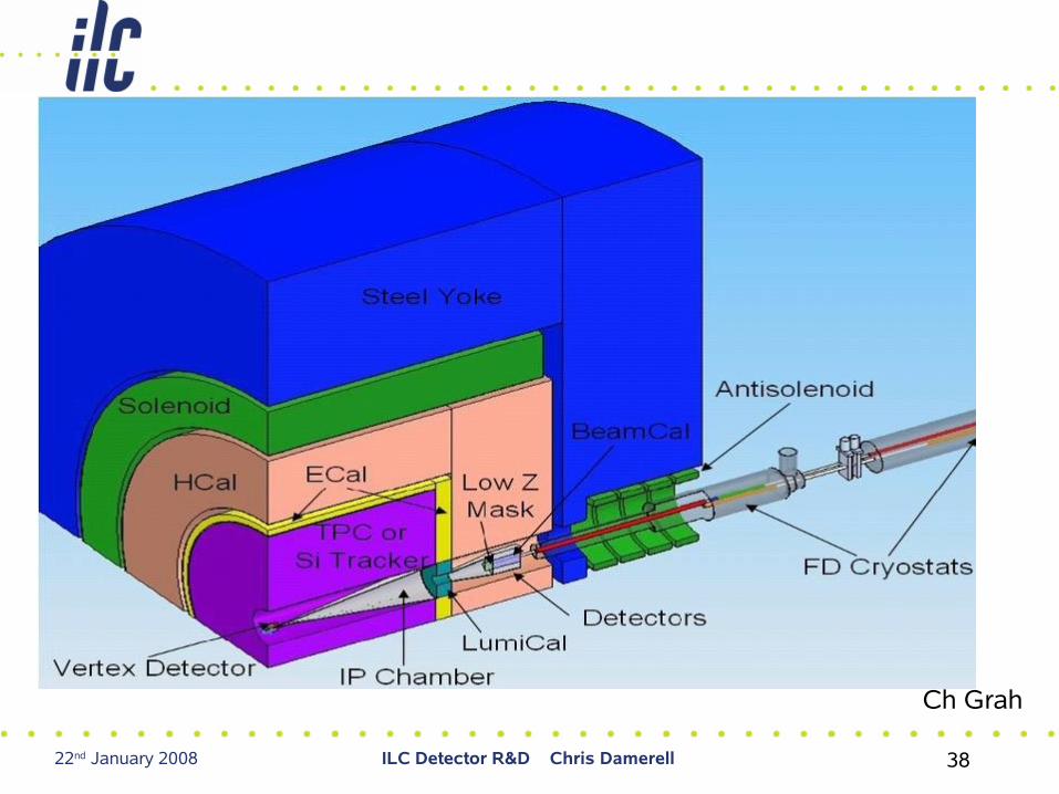
22nd January 2008 ILC Detector R&D Chris Damerell 38
Ch Grah

22nd January 2008 ILC Detector R&D Chris Damerell 39
• Two main categories:– Very forward calorimetry (precision luminosity, hermeticity, beam
diagnosics)• FCAL Collaboration (15 groups)
– Doing a great job, but need additional resources, specially in USA
– General calorimetry (precise jet energy measurement in multi-jet events, ∆E = 30%sqrt(E)
• PFA approach: CALICE collab (41 gps), SiDCAL collab (17 gps, some in CALICE)
• Compensating calorimetry: DREAM collab (8 gps), Fermilab gp
– We were not able to exclude either option: much more work is required (and we might eventually need both to do the physics: PFA in barrel and compensating calorimetry forward)
Overview of the review

22nd January 2008 ILC Detector R&D Chris Damerell 40
Tasks of the Forward Region
IP
•Precise measurement of the integrated luminosity ( L/L ~ 10-4)•Provide 2-photon veto
•Provide 2-photon veto•Serve the beamdiagnostics using beamstrahlung pairs
5mrad
~40mrad
~150m
rad
•Serve the beamdiagnostics using beamstrahlung photons
Challenges: High precision, high occupancy, high radiation dose, fast read-out!
Ch Grah

22nd January 2008 ILC Detector R&D Chris Damerell 41
• Impressive report – physics requirements and technical implications were clearly presented
• Design of LumiCal and BeamCal well advanced – GamCal (BS monitor) studies are at an early stage
• BeamCal sensor development profits from close collaboration with groups developing rad hard sensors for hadron machines, notably sLHC
• Need increased funding for travel, for their dedicated US collaborators (even before FY08 disaster), and for system-level engineering
Main technical recommendations (FCAL)

22nd January 2008 ILC Detector R&D Chris Damerell 42
• All studies to date (beyond the experience with first generation systems at ALEPH and SLD) are based on simulations
Main technical recommendations (PFA systems)
• These are only the average shower radii. There is even greater uncertainty in the shape variability between individual showers, initiated by different inelastic scattering processes
• Simulations alone cannot be trusted. Given the need to disentangle hits from charged and neutral showers, data are needed on both, in large-scale ‘physics prototypes’ to:
• Establish the performance truly achievable with such a calorimetry system• Establish what HCAL sensor arrangement (scintillator, RPCs, etc) will give the best
performance

22nd January 2008 ILC Detector R&D Chris Damerell 43
Mark Thomson

22nd January 2008 ILC Detector R&D Chris Damerell 44
• Some progress since our review (Jose Repond, Rajendran Raja) in establishing practical conditions for calibration with tagged neutrals (neutrons, KL , even anti-neutrons) using the MIPP2 facility in MCentral beamline at Fermilab Previously mentioned problems such as DAQ can be overcome
• Nobody is suggesting to run the simulations using shower libraries of these data, but comparing simulated shower shapes with data, then tuning simulation parameters to match well the data, is considered realistic
• Vertex detector and possibly tracker will surely be upgraded during ILC running, but not the coil or calorimetry – we do need to get these right when experiments choose their technologies

22nd January 2008 ILC Detector R&D Chris Damerell 45
• PFA performance will surely degrade in the forward region, where for t-tbar and much BSM physics, one or more jets will generally be directed
• Cannot afford to let the tracking ‘go to hell in the forward region’ as in the past, but even if that is robust, the poorer momentum measurement will degrade the PFA performance
• Less spreading of charged tracks may favour a hardware compensating calorimeter and a pfa approach (John Hauptman terminology)
• Make no attempt to resolve the particles in jet cores, within the calorimeter
• Crystal EM section, with dual readout of scintillation and Cerenkov light by timing , followed by a hadronic section with dual readout by quartz and scintillator fibres: no longitudinal segmentation, but SiPMs and local readout chips permit excellent hermeticity. HCAL thickness 10 λ or more
• Claim they could achieve ∆E = 20-25%sqrt(E) for isolated jets. No idea yet how well their pfa will sort out the complications in multi-jet events
Main technical recommendations (compensating calorimetry)

22nd January 2008 ILC Detector R&D Chris Damerell 46

22nd January 2008 ILC Detector R&D Chris Damerell 47
• Before moving to a large scale prototype, the review recommended they investigate a number of concerns, some by simulations, others by lab tests
• Their collaboration is very short of people, and we are doing our best to encourage others to help. Their approach could prove to be the outright winner in the so-far-neglected forward region. Would a mixed system (PFA central, and dual readout forward), possibly be optimal?

22nd January 2008 ILC Detector R&D Chris Damerell 48

22nd January 2008 ILC Detector R&D Chris Damerell 49

22nd January 2008 ILC Detector R&D Chris Damerell 50
Vertexing Review Committee
• Panel members: Chris Damerell, Hwanbae Park (chair) • External consultants: Yasuo Arai, Dave Christian, Masashi Hazumi,
Gerhard Lutz, Pavel Rehak, Petra Riedler, Steve Watts
• Regional representatives: Tim Bolton, Chris Damerell, Junji Haba)
• RDB chair: Bill Willis
• Local vertexing experts: Simon Kwan, Lenny Spiegel
• Admin support: Naomi Nagahashi
• Report not yet completed – blown away by the UK funding crisis, ~50 e-mails per day since 11th December. WILL be done by time of Sendai workshop

22nd January 2008 ILC Detector R&D Chris Damerell 51
Optimal geometry (long barrls, or short barrels plus end-discs, will depend on ladder-end details that are not yet defined for any technology

22nd January 2008 ILC Detector R&D Chris Damerell 52
• Imagine p and p+ material brought into contact at same potential
• Holes pour from p+, leaving a negative space-charge layer (depletion) and forming a positive space charge layer in the p material (accumulation)
• This space-charge must of course sum to zero, but it creates a potential difference, which inhibits further diffusion of majority carriers from p+ to p and incidentally inhibits diffusion of minority carriers (electrons) from p to p+
• This barrier is thermally generated, but the ‘penetration coefficient’ is temperature independent, and is simply the ratio of dopant concentrations. eg 0.1/1000, so 10-4 - this interface is an almost perfect mirror!
Minority carrier diffusion length
~ 200 µm
------------------------------
~ 0.1 µm
What epi-layer thickness?
Prefer it thin, to avoid losing precision for angled tracks
But not too thin, or lose tracking efficiency
20 µm is ‘about right’

22nd January 2008 ILC Detector R&D Chris Damerell 53
• We can repeat this on the top surface – here the p-well can be used to implant structures (notably n-channel transistors), ‘monolithic’ with respect to the detector layer below
• Positively biased n implants (reverse-biased diodes) serve to collect the signal charges, partly by diffusion, partly by drift in depleted regions created in the p-type epi layer
• Overlaying dielectric layers, and photolithographically patterned metal layers complete the toolkit for interconnecting the circuit
• Here you have the essentials of a MAPS (monolithic ‘active’ pixels sensor, having transistors within the pixel; in contrast to ‘passive’ CCDs)
•To learn about all the beautiful options for ILC vertex detectors, refer to the website of the ILC Detector R&D Panel at https://wiki.lepp.cornell.edu/wws/bin/view/Projects/WebHome

22nd January 2008 ILC Detector R&D Chris Damerell 54
• Pioneered by W F Kosonocky et al IEEE SSCC 1996, Digest of Technical Papers, p 182
• Current status: T Goji Etoh et al, IEEE ED 50 (2003) 144
• Frame-burst camera operating up to 1 Mfps, seen here cruising along at a mere 100 kfps – dart bursting a balloon
• Evolution from 4500 fps sensor developed in 1991, which became the de facto standard high speed camera (Kodak HS4540 and Photron FASTCAM)
• International ISIS collaboration now considering evolution to 107 – 108 fps version!
ISIS: Imaging Sensor with In-situ Storage

22nd January 2008 ILC Detector R&D Chris Damerell 55
• charge collection to photogate from ~20 µm silicon, mainly by diffusion, as in a conventional CCD
• no problems from Lorentz angle
• signal charge shifted into storage register every 50µs, to provide required time slicing
• string of signal charges is stored during bunch train in a buried channel, avoiding charge-voltage conversion
• totally noise-free storage of signal charge, ready for readout in 200 ms of calm conditions between trains
• ‘The literature is littered with failed attempts …’

22nd January 2008 ILC Detector R&D Chris Damerell 56
~50 µs
Baseline settles to a different level after each reset, due to kTC noise
‘uncorrelated double sampling’

22nd January 2008 ILC Detector R&D Chris Damerell 57
SLC Experiments Workshop 1982

22nd January 2008 ILC Detector R&D Chris Damerell 58
SLD’s Vertex Detector Design in 1984

22nd January 2008 ILC Detector R&D Chris Damerell 59

22nd January 2008 ILC Detector R&D Chris Damerell 60
As with developments in microelectronics, we (the particle physics community) are now small fish in a very large pond.
In the ’50s and 60s, fast electronics was synonymous with ‘nuclear electronics’
These days, progress driven by consumer markets is much faster.
We scientists can be very grateful for that …
22nd January 2008 ILC Detector R&D Chris Damerell 61

22nd January 2008 ILC Detector R&D Chris Damerell 62
• What will 2008 hold for ILC Detector R&D coordination?
• Progress report from R&D Panel at TILC08 in Sendai in March
• Suggest that the Detector Directorate and IDAG consider the possibility of inviting R&D groups to form TBCG, TCG, CCG and VCG. Many (but not everyone) in the community would welcome them
• LOI groups will provide essential guidance by developing integrated systems (even if only working towards ‘practice’ EDRs, as they must be)
– May lead to clear synergies and also some exclusion principles
• Question of when to hold the remaining first-round R&D review, and when to start the second round: may be prudent to delay till further progress has been made
• Eminent Japanese accelerator physicist (not in ILC): “The activity of the ILC seems to be much thicker in the head and thinner in the body. I mean there have been so many meetings and phone conferences. On the other hand quite a small number of people are doing the R&D”

22nd January 2008 ILC Detector R&D Chris Damerell 63
• STFC DP 11/12/07 and K Mason to HoC Sel Comm 21/1/08 “The ILC project as currently conceived is not viable”
• The UK PP community is 100% united against this, and is fighting on a number of fronts, most importantly our international responsibilities, and potential damage to our reputation as reliable partners
• How YOU can help:– Wolski (DRs)– Clarke (positron source)– Burrows (MDI)– LCFIVertex (group effort)– CALICE(UK) (group effort)
• Please don’t give up on us yet. As long as these efforts aren’t replaced, we will be able to use the argument that the world is counting on us to deliver
• The recovery campaign is only beginning: it will not be easy, but with your help, we can win this one
UK position
Over 100 excellent physicists and engineers