ill - defense technical information center · ill distributed by: national technical infonnation...
TRANSCRIPT

AD-771 046
HYPERBOLIC -FM (CHYPE)
Charles J. Kiss
Aray Missile CommandRedstone Arseaal, Alabama
1 October 1973
Ill
DISTRIBUTED BY:
National Technical Infonnation ServiceU. S. DEPARTMENT OF COMMERCE5285 Port Royal Road, Springfield Va. 22151
II .I. I 4
_---.

tUiCALS51FIED q .7 71 d 66secuity Classification
DOCUMENT CONTROL DATA. R& D(S.oeutity cleasifcaion of fill*., body of abstract and indexing onnoteri or. must be entered when the overall report to classlled
I -OR GINATI N ACTIVITY (Corporate e.JAor p fZ*. REPORT SECURITY CLASSIFICATION
* US Army Missile Research, Development Unclassifiedand Engineeving Laboratory 2b. GROUPus Army Missile Command 189NRedstone Arsenal. Alabama 389N3 REPORT TITLE
HYPERBOLIC-FM (CHYPE)
4. OESCIRIPTIV NOTES (Type of ,epoet an~d Inclusive doses)
Technical ReportS. AU TNORM5 (Firet 118810. middle Initial. ls noose)
Charles J. Kiss
0. REPORT DATE 70. TOTAL NO. OF PAj 1 S b. No. or mREs
1 October 1973 4&. '10$40. CONTRACT OR GRANT NO Se.ORIGINATOR'$ RieOR NuwaitE~RI)
b PRtOJECt NO. (DA) 1T061102B31A03 RE-73-32
c. AMC Managemen~t Structure Code No. Wh. OTHER REPORT Hoist eAny othernumbe, 81ttmsy be **signed
5011 .11 .85400 thsrport)d.
10. 0I5TRIBUTION STAENT
Il. 4UPPLEkf9NTARY NtOTCS 12. SPONSORING MIL-TARY ACTIVITY
None Same as No. 1
13. AGSRACT
This report investigates a hyperbolic frequency modulation technique that isdoppler invariant. This doppler invariant prwperty assures its usefulness in boththe realms of acoustic echolocation and radar. Bat echolocation techniques arediscussed and are shown to be surprisingly analogous to current radar techniques.Spectral characteristics of the compressed hyperbolic-FM are examined with respectto its pulse compression capability in extremely high velocity target environmentsand is shown to be superior to the conventional linear-FM. Matched filtering issimulated via an Il-bit Fast Fourier Transform.
kot~poducd by
NATIONAL TECHNICAL .
INFORMATION SERVICEU S D ownI.- cf Cornc
S:,g~iiVA 22151
1'
DD 1004A17 @3E21"1 RM UE UNCLASSIFIED
/ - secuarity clammiflcation

"71T7 -. 7--7 7- -
UNCLASSIFIEDSecurity Ciessifictilon
14, K91 W LINK A LINK a LINK C0_ROLE WY ROLE I WT ROLE W T
Echoloca tionChirpChype
UNCLASSIFIEDseciaity Classification

DISPOSTION INSTRUCTIONS
DESTROY THIS REPORT WHEN IT IS NO LONGER NEEDED. DO NOTRETURN iT TO THE ORIGINATOR.
DISCLAIMER
THE FINDINGS IN THIS REPORT ARE NOT TO BE CONSTRUED AS ANOFFICIAL DEPA.RTMENT OF THE ARMY POSITION UNLESS SO DESIG.NATED BY OTHER AUTHORIZED DOCUMENTS.
TRADE NAMES
USE OF TRADE NAMES OR MANUFACTURERS IN THIS REPORT DOESNOT CONSTITUTE AJ OFFICiAL INDORSEMENT OR APPROVAL OFTHE USE OF SUCH COMMEHCIAL HARDWARE OR SOFTWARE.
///

CONTENTS
Page
1. Intrcduction . 3
2. Matched Filters .. . .. . . . . . ... .... .. . ..... . 43. Frequency Modulation ............. . .. . 54. Doppler Effect . . . . ... ... ... . . 65. Linear-FM (Chirp) .. ..... . . . . . . . 86. Hyperbolic-FM (Chype) .............. .. . 97. Echolocation ..... .................... 128. Simulation .... .................... 139. Results and Conclusions ................. 15
References .............. ...................... 38
Appendix A. TYPICAL PROGRAM USED IN SIMULATION . ....... 39
I

1. Introduction
Today, radar a'.d sonar systems depend heavily on pulse com-pression processing. Ih,- use of high time-bandwidth product (T B) orpulse compression wavuf',;)rms in these systems has been considerablyinvestigated and refined in the past 10 years. This investigation hasfor the most part been focused on the linear-FM or chirp modulationwhere the ftequency sweep is linear over the pulse. This is quitenatuzal due to the linear-FM waveform's suitability in illuminatingtoday's class of relatively slow moving target and its ease of genera-tion and application. State of the art delay line technology hassatisfactorily established single pulse time-bandwidth products on theorder of 1000.
Linear-FM modulation loses its effectiveness, however, when usedin a high velocity target envir,,nment. A limit is placed on the radar'smaximum attainable compression ratio which stems from doppler distor-tions of the compressed pulse. Put simply, the faster the target, thelower the effective compression ratio. While this may not presentextreme difficultie3 for today's surface based radars due to the"relatively slow" velocities of aircraft and missiles being illuminated,a situation can already be forseen where accurate resolution cC satel-lites or space probes utilizing ultra-high time.bandwidth product
signals would be inadequate if illuminated by the familiar linear-FMwaveform. Doppler distortions would render this type of modulationsomewhat ineffectual.
This report will examine a modulation scheme commonly calledhyperbolic-FM or linear period modulation that appears to be wellsuited for matched filtering in a high targ.t doppler enviromrent.Interestingly enough there is mounting evidence that this modulationcould well be that used by hunting bats.
Acoustic orientation by bats and porpoises has been recognized forsome time. Spallanzani in 1793 performed experiments with bats thatled him to conclude that "the ear of the bat serves more efficientlyfor seeing, or at least for measuring distances, than do its eyes."Various researchers throughout the years have materially added to the
..knowledge pertaining to bat echolocation. Griffin's work 1I) clearlyestablished the adaptive nature of the bat echclocation technique.While not all species of bats are sightless or employ echolocation,those that are -ndowed with poor visual perception are typically theones that have developed extraordinary echoloostioti capabilities. Ttseems that this widely frAsrepresented matmoal has im plemented for eons alocation and ranging technique which man has only recently discoveredIn particular, it appears thet the modulation of the bat's tranamittedsignal, which possesf-s time-bandwidth products significantly greaterthan unity, is stru tured such that insect velocities create little ifany egradation of the received processed signal. It will become evidenttha there exist some astonishing parallels between bat and 'zatar/sonsrsig l processing.
3
-icig pgo MW

2. Matchd Fil trm
A filter is said to be matched to a waveform if the filter'simpulse response, h(t), is the time inverse of the input waveform,s(t). A delay is generally introduced to avoid the problem of non-causal input-output relationships:
h(t) --: ks(-t + d)
Correspondingly in the frequency domain this transformr, into:
H(.j) = Ks*(ti) e-y
where s*() is the complex conjugate spectrum. The output of thisdevice becomes by convolution:
y(T) a k f s(t)s(t + "r - "didt
Sss(- - d)
and/or
¥( = K )s(); 2 e-j :.nd
These are the basic equations pertaining to matched filtering where
(ss(g) is the autocortelation function of the signal s(t). It should
be noted thac while matched filtering has been shown to effeccivelymaximize signal-to-noise ratios in a white noise environment, it is byitself not a pulse compressive or tise-bandwidth product compressivedevice if the waveform to which it is matched is itself of unity time-bandwidth product, i.e., a rectangular pulse. For any signal to be
capable of undergoing pulse compression it must of necessity possessphase dispersion in the frequency domain, or alternativelv Phase orfrequency modulation in 'he time domain. Phase dispersion is thatpart of a signal's phase spectrum that is a nonlinear function offrequency. A signal such as a chirp waveform that posscsses phasedispersion or phase modulation will by definition have a greater thanunity time-bandwidth product. A matched filter will process this wave-form in such a rnanne: that will reduce its time-bandwidth product tounity, thereby removing the phase dispersion. This results in an ampli-fication and compression of the input waveform.
'4
This entire Phenomenon can alternatively be viewed as follows: acompressive signil containing phase dispersion is passed through anutched filter. The filter is tailored to this signal in t,at itsphase disperslon is equal to but opposite that of the signal's, therebyvancellig or, removing it. This results in no phase irregularities inthe proces.ed signal spectrum so that it is altered, i.e., distorted.This form of distortion is desirable in that it is in the form of anarrower pulsewidth with gre ter peak amplitude.
The usefulness of pulse compression effectively lies in the areasof increased power and resolution capabilities. By resolution, onemeans how well multiple targets can be resolved in range and/or velocity.
Maximizing a system's detection capability requires maximizing theenergy content of the received signal. This can be done simply byamplific.ation or elongation of the transmitted pulse. Unfortunatelytransmitters are peak power Limited and an arbitrary increase in pulseamplitude is not possible. Likewise, increasing pulse duration degradesrange resolution capability for extended targets and r?quires the radarto become blind to close-in targets for a longer period of time. Pulsecompression affords a means of transmitting a long (poor range resolu-tion) low amplitude modulated pulse of high time-bandwidth product,receiving it, matched filtering it to obtain an amplified, narrow(good range resolution) pulse. Basic receiver simplicity is lost inthis process. System complexity has significantly increased due todelay line sensitivities, weighting networks, gain and phasetolerances throughout the entire processing chain, and possibly multi-channel signal processing.I 3. Fmoqusnc Modlatio
Having shown that some form of modulation is essential to thepulse compression process the question naturally arises as to whattypes of modulation are suitable or even optimum in some ,ense. Thisbasic although nebulous area will not be discussed in this reportexcept to state that the system designer must know a priori what thetactical situation is before even beginning to attempt to answer thisquestion. He must be aware of a host of possible pitfalls such as peakpower requirements, range and velocity resolution, delay line technology,ECH, clutter environment, sidelobe requirements, target veloc4tes,accelerations, etc.
This report is limited to the investigation of two modulationfunctions: the linear-FM or chirp and the hyperbolic-FM or chype. Theparameter of interest is the waveform's sensitivities to target doppler.It is believed that these modulation functions are rignificant enoughto warrant this special consideration. The chirp modulation is cur-rently the most utilized o-, available and is indicative of today's
5

state-of-the-art in pulse compression radars. The chype modulation, onthe other hand, has only recently begun to be investigated based inpart on its apparent occurrence in nature, namely in bat and porpoiseecholocation. The apparent suitability of chype modulation and non-suitability of chirp modulation with respect to a high velocity targetenvizonment is the basis of this report.
4. Dopper Effc
A moving target has the effect of translating cie impingingillumination frequencies associated with a signal according to theequa tion:
f r = - ftLr
whe re
ft transmitted frequency
f = received frequency
v = target velocity
c = velocity of propagation
a 2v/c.
The doppler frequency shift, fd = t f r' becomes
t
It is readily seen that higher frequencies undergo a larger dopplershift thin do lower frepzencies. This has the effect of dilating orcontracting the received signal spectrum as well as contracting urdil ting the signal itseh.r. This doppler phenomenon results in asignal whose spectrum is not only shifted, but whose bandwidth has alsoseen transfvrmed:
6

Likewise, its pulsewidth T has been transformed; AT A .1 as a resuLt
of target motion during the illumination interval T. As a consequence,a signal reflected from a closing target will appear at a higher carrierfrequency, wider bandwidth, higher PRF, and narrower pulsewidth. Inlight of matched filtering or pulse compression processing, the signaland filter are now considerably ,isatched. The doppler phenomenoneffectively imposes additional phase dispersion which the matched filtercarnot compensate for. This causes a widening of the resulting comn-pressed pulse as well as a growt!h in its sidelobe structure. Thisgrowth of sidelobe Jutter is undesirable since it tends to mask weakersignal ruturns.
These target effects are relatively undiscernable for many currentradar applications. In sonar envirorments, however, the doppler effeztis accentuated and considetation of the problem is warranted especiallywhen using high time-bandwidth vaveform.3.*
The typical narrowband approach to the effects of doppler is toapproximate it by a simple frequency translation. In this report theexact doppler phenomenon i, used since it and not its approximationimposes the ultimate limit on amplitude and phase distortions of pulseenvelopes and their modulation functions. The narrowband approximationis tantanount to assuming a chirp signal's doppler effected modulationfunction to be a mere translation witn no rotational effect (Figure 1).While this is a valid approximation for low tire-bandwidth products(narrowband signals) it does not indicate the waveform's actual limita-tion inposed by a high enough doppler. Given a transmitted waveform,s t(t), it has been shown that the doppler received signal, s (t), is of
the form 12j:
S r~t . .- (at)
where
2
The question of how much doppler shift can be tolerated by the modula-tion function of a pulse compression waveform is discussed next inreference to the chirp 3nd chype waveforms.
*The velocity of sound in air is approximately 335 m/sec as opposedto 1500 -P/sec in sea water. Electromagnetic energy is radiated at
approximately 3 1. 108 M/sec.
7

5. Liner-FM (Chirp)
The downswept linear-FM waveform can be expr,.ssed as:
s(t) = k cos t -- t 0 -< t -T
where
= carrier radian frequencyC
radian sweep rate 2nB/T
B = bandwidth
T = pulsewijth.
The instantaneous phase variation is quadratic so that its frequencymodulation is linear. ,At any instant of time within the pulse,
(t) ()idt = c
The doppler induced distortion of the modulation function causes thereceived pulse to appear as:
s(t) ak cos t uit t
so that
= cgit rl -
If an instantareous period is considered (corresponding to the zerocrossings of the modulation function) it is seen to vary in a hyperbolicfashion:
T 2x T Tct
Ti= c

where Tc corresponds to 2r./' I . These relationships are illustrated in
Figure 1 where it is apparent that in the peesence of doppler, thetrarwmitted and recei,-ed modulation sweep tates are different and can-not be brought intu. coincidence or matched with a mere shift in time orfrequency. This increase or decrease in modulation slope Li a con-sequence of the doppler center frequency shift and bandwidth trans-formation. What is evidently optimum in a doppler seme is to have themodulation functions of transmitted and received waveforws equal so thatno decorrelation or degradation in the. compressed pulse will occur.
The linear-FM imodulation function while not posesting the idealinvariance to doppler is in fact tolerant to wild case.* of dopplerespecially if the matched filter bandwidth is slightly larger thanrequired to accommodate small doppler shifts and minuimize temporallosses. Its limit of tolerance can be intuitively tArrLved at by con-sidering a typical return from a closing target. La such a case thepulseidth is shortened, T' = T(I - j) so that T' - I- A T- T- AT.If -*, approaches -18 in magnitude, significant distortions will resultfrom matched filtering. Therefore, LT < -' IfS o / - 1/5 or finally:
TB- I
As stated earlier, this implies that for a higher pulso- compressioneffect, slower targets must be illuminated. Thor 131 depicts the effectsof utilizing high time-bandwidth product signals in a high velocity tar-get environment and roughly sets the limit of chirp compr . sion ratiosat 10,000. This seevingly academic limitution radically changes if aspace environment is considered. A case in point is the NationalAeronautic and Space Administration's GrAnd Tour of our solar system'souter planets. Velocities attainable by. such payloads approach 25,000meters/second (55,000 mph) in the vicin.ity of Saturn. For such radialvelocities, linear-FM would be limited to time-bandwidth products on
the order of 600 in lieu of a significant increase in receiver com-plexity to avoid Joppler distortions.
6. Hypewboc.FM (Chbgw)
The derivation of the hyperbolicFM mdulation function hasbeer. arrived at by various author-i (4, 51 most notably be equatingtransmitted and received modulation functions. Hyperbolic-FM can beexpressed as:
s(t) k co in I . 0 - t -I T
9

The instantaneous phase variation is logarithmic so that its frequencymodulation is hyperbolic. As Kroszczynski points out [51, this causes thezero crossings to act linearly and thus calls the process linear periodmodulation:
2C+ (t)
c
and/or
(t) -T +i
The doppler induced distortions of these modulation functions can beexpressed as:
2
c
and/or
T(t)- T
These relationships are depicted in Figure 2. By comparing Figures 1and 2 an interesting observation can be made: a simple timeshift cannot cause coincidence in the chirp case as it can in thechype case. This shift in time is easily calculated from Figure 2 andis expressed as:
ts c. (a-I)
It is interesting to note that for the chirp case the pseudoperiodmodulation is hyperbolic. One can simply view this as a reversal inthe structure of time and frequency modulations between the twowaveforms.
10

Based upon use of chype modulation it is seen that for an addi-tional delay of t seconds during correlation by the matched filter,S
complete coincidence or correlation will result. This simply meansthat no degradation of the doppler "degraded" compressed pulse willresult. If one returns to the concept of spectral phase dispersion,it is clear thaL no additional phase dispersion is introduced by thedoppler effect that cannot be coped with by a coirelation delay. AsRihaczek [61 points out, however, chype modulation does casue ambigiousrange-velocity measurements since multiple targets at certain keyranges and velocities are rendered ambigious.
In attempting to gain insight into the frequency domain spectralcharacteristics of the hyperbolic-FM waveform, certain difficulties,re encountered. Contrary to the chirp spectrum which is readilyexpressed in terms of Fresnel integrals (which are well tabulated),the chype spectrum as derived by Kroszczynski (51 takes the following,rather complicated, form:
2S( -- - exp j [in . '0 1 n ((2 ) +
r 2
5C ' C ;
In the above exp"t..sion, Y is the incomplete ganmma function.* Sufficient
tabulation of this function is nonexistent with respect to complexarguments. As j result, a numerical Fast Fourier Transform (FFT)approach was used for this analysis.
A further interesting resemblence between the chirp and chypemodulations becomes evident if the argument of the chype waveform isexpanded:
2n t 4 +.
W c 2 +3 w±
* y
Y(x, Y) -f e eppXldp.
0

For low velocity targets and compression ratios the higher terms in thee\pansion become negligible, resulting in the chirp modulation function.Both the chirp anw chype modulation functions result in the same basicpseudo sin x/x compressed pulse structures. While the chirp is boundby the criteria of ,TB 1, the chype is not. In this sense, chypemodulation can be considered doppler invariant whereas the chirp at bestcan only be considered doppler tolerant.
7. Echolocation
The most interes ting assortment of fact relating to acousticeholocation by bats has only recently been postulated. Based on thetaWtLical situations confronting these mammals, some astonishing parallelsbetwuen bat echolocation and radar/sonar signal processing becomesevident. Specifically the discussion is limited to Myotis lucifugusand Eptesicus fuscus of the family Vespertilionidae. The ultrasonic*pulAes transmitted by these bats are highly modulated and their duration,repetition interval, and bandwidth are adapted to the target environmenton a pulse to p,,lse basis. The search or hunting phase of their trans-mission is characterized by pulse durations on the order of 5 msec,decreasing to approximately 0.5 msec in the terminal phase prior tointercept. The pulse repetition rate during this same interval typicallyincreases by a factor of 10. Investigations have indicated that thefrequency modulation associated with the outgoing sonic pulse takes theform of a nonlinear downward sweep in frequency of approximately oneoctave. While this octave sweep is a relatively constant feature, itis nevertheleLss agile in that one pulse may sweep from 80 to 40 kflzwhil2 another may sweep from 60 to 30 kllz, depending on the tacticalsituation. These data indicate time-bandwidth products in the range20 to 200.
The most intriguing aspect concerning bat echolocation has onlyrecently been postulated. Experiments [7J now indicate that matchedfilter processing may be taking place in the inferior colliculus sectionof the brain. This highly developed area of their brain has been shownto possess neuron types ideally suited for target ranging (8]. Apparentlytheir brain stores or memorizes the transmitted ultrasonic signal andcorrelates it with the received one. A linear frequency sweep or chirpif used by them for echolocation would be greatly limited by dopplerin that .'TB I. Here .' = 2v/s, where s is the velocity of soundin air (approximately 1.1 ft/msec). Assuming a bat-insect velocity of15 ft/sec** and a time-bandwidth product of 100, .'TB Z, 3. This would
*The high frequency limitation of the human ear mechanism, generally
taken as 20 kliz, render these rather strong ultraaonic pulses (20 to100 kliz) inaudible.
**Griffin [11 reports velocities for myotis lucifugus in the laboratory
on the order of 8 20 ft/sec.
12

result in severe degradations of the compressed pulse as indicatedearlier in this report. When this is considered in light of experi-i,,ental data indicating a near hyperbolic frequency sweep [9], one can-not help but be cognizant of the doppler invariant nature of this typeof modulation when applied to a high velocity insect environment.
Thc concept of bat pulse compression is reinforced if the spatialresolution capability of the expanded and compressed pulses ib considered.A typical 40-kilz sweep over a 2-irsec pulse duration results in a spatialpath length of approximately 75 cm in air. Such a pulse length isincompatible with the fine resolution requirements of hunting bats.However, if matclTed filter processing is assumed, the compressed pulsegenerated in the bat brain as a result of the correlation process thenhas a processed width of 7.5 mm (75 cm/TB). This coincides with theobserved resolution capability of Eptesicus in the laboratory.* Exami-nation of the bat's digestive tracts subsequent to feeding amidst denseinsect swarms indicates prey whose wingspans and body dimensions aretypically on the order of 5 to 25 mn.
It should perhaps be recalled that the pulse compression techniqueaffords a means of circumventing inherent limitations of signal trans-mission, regardless of whether it is in a radar's 1T or a bat's larynx.The matched filter, in addition to increasing range resolution capabil-ity, -,maximizes target detectability and signal to noise ratio. Thiscould explain the capability of bats to process extremely faint echo
returns (10- 3 dynes/cn 2) under natural conditions, which up to now hasaot been satisfactorily explained.
With respect to another possible occurence of chype modulation innatire, Kellogg [101 indicates that the porpoise "whistle" sweeps fromapproximately 7 to 15 kHz over a 0.5 second interval. T;,is approximate
one octave sweep would result in a time-bandwidth product of 3750. Inlieu of chype modulation, chirp modulation would be limited to veloc-ities smaller than 0.25 m/sec in sea water. This is hardly compatiblewith hunting porpoises.
8. Simulation
It was desired to simulate matched filtering of the hyperbolic-FM modulated pulse to ascertain the structure of the resulting compressedpulse for both stationary and high velocity targets. A one-octavefrequency sweep was used for the chirp and chype waveforms since thisrepresented a seemingly conmon occurence in nature. The preliminary
*It should be noted that Myotis has been observed to avoid 1 mm wire
obstacles under controlled laboratory environments.
13

difficulty Ofa tquating swe:pt bandwidths of the se two modulation functionswas overcome by itiakiog the following equality:
I ch ("c - 1T)
where
h chype sweep rate
i chirp sweep rate
f pulsewidth.
A signal ime-bandwidth product of 100 was used (TB 50 and 200wtre also run) such that 0 ' TB ' 6. Tbe simulation itself was basedon the use of an Il-bit FFT technique. It should be pointed out thatwhile the FFT approach afforded an economical method of computation itwas in no way optimized for minimum run time. A typical listing of theprogram is provided in the appendix. Suitable precautions were taken tominimize various distortions associated with the FFT. This entailed useof a suitable "zero fill" and an analytical signal approach. The zerofill was approximately 80 percent for the forward transforms. No zerofill per se was made for the inverse transform case since this necessitywas obviated due to the fact that after spectrum multiplication by thematched filr.ter, data values without the system's passband were alreadyeffectively zero. The analytic signal approach was utilize'd L, minimizealiasing distortions associated with the sampling process. The realsignal under investigation, s(t), is inputted as:
.(t)- s(t) + jt(t)
Here (t) is the analytic counterpart of s(t), where (t) is theHilbert transform of s(t):,
9(t) s(t) * -irt
The matched filtering or correlation in the time domain becomes amultiplication of spectral amplitudes and an addition of spectral phasesin the frequency domain. In conjunction with a suitable inverse FFToperation the matched filter output is obtained. Figure 3 illustratesthe program philosophy.
14

9. Results and Conclusions
Figures 4 t'hrough 7* illustrate the compressed chype pulsespectra for the zero doppLer case. A spectrum ripple effect is presentwhich ,ippears to he inversely proportional to the waveform's time-bandwidth product. ThLs ripple is analogous to the "Fresnel ripple",assoc ated with the compressed chirp pulse spectra, and in the samesense it can therefore be denoted as "gamma ripple." This ganviia ripplewould cause somewhat inferior compressed pulse performance for very low
time-bandwidth products (T 13 20) as in the chirp case.
Figures 8 through 13 clearly depict the high degree of dopplerdistortion in the compressed chirp pulses as opposed to the almostnegligihle distortion in the compressed chype pulses for the varioustarget velocities examined. In Figures 12 ;nd 13 ther' appear to betwo target returns in the chirp case as opposed to tht one true strongreturn in the chype case. In this respect chype is invariant to targetdoppler. The ,hype modulation is of course not totally "doppler invari-int." 'emporai overlap losses do oc Ur for high enough doppler causinga corresponding lobs in compressed pulse peak amplitude.
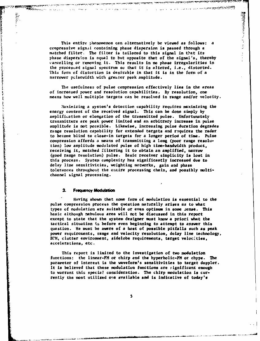
Figure 16 0hows a comparison of two compressed chype pulses whosetime-bandwidth products are 30 and 200. it can be seen that theirstructure is the same over their mainlobes although there is someslight difference in their sidelobe structure. This is most likely dueto Cie characteristic spectru. ripple being different for the two wave-forrts, thusc iusing z. slight redistribution of energy over the totalpulse durition. Figiir s 17 through 20 illhstrate the total compressednulse sidelobe .tructure (existent over T) for varying degrees ofaopplur. Here, mainlobe width is seen to be itzvariant (Figures 8 through13) for the chype modulation. Sidelobe levels do vary as a function ofdoppler, but they do not increase to any substantial degree.
Figures 21 and 22 are a comparison of chirp and chype modulations(T • B - 100) with respect to maximu.m, compressed pulse amplitude andpulsewidth. The immunity of chype to high velocity target effects isself-evident. Based on these two plots the condition for degraded chirpoperation can be taken as approximately rTB - i, and in fact this hasbeen the approximtation put forward by various authors.
• Figures 4 through 7 and 17 through 20 are a result of the Q1UIK3V com-puter plot subroutines. Figurces 8 through 16 are a result of a fourthdegree Lagrange interpolation scheme as applied to 50 computer gener-ated data points.
15

cl\- TRANSMITTED
"---- RECEIVEDcN
Ti LINEAR FREQUENCY MODULATION
/
/
T /
HYPERBOLIC PERIOD MODULATION
F-igure 1. Chirp modulations.
16

-TRANSMITTED
--- RECEIVED
t
wc
LIERi FREQU0NCODU LATION
F i ore . Chypernoo LaLios
Il7

ILI
I. x 96 C6o
ijiIx CL
W Wx x
Ucc
Ul.
UA.8 U,
W6 W6I x
U. U)W.
LW18

0.0004- 1 1111 A I t- II III I I
I0.0003- 1]
Fiue .C0002sdch--setrm C B=50-ct-)
L19

LL
0.00
0.00020.6
02

rr
III i g r e 6 . C t i p e s e d c h p e s e c ru0(.0B0011 2o c a v )
_q 21

. . . . . ... . . . . . .. . .
0.0016 .. ... ................ - ------ XXT-M-11 .......... ........... .............................. M
....... ........ .... .........------ ........ ... ..............-XITITT-11
.............. ^ ......
0.0014 ....................
....... . ..U:
0.0012 ......
LlallAl I
0.0010 kill
0.0008
... ... ......
TIT
0.0006 ......
"T
X-----------
0.0004 -LI L ... .............. ..A I ::::: - ::::: ----------- -.... ....... ....... ..
11 it fit fAIL4
0.0002T
00 OM 0.06 0.12 0.16 0.20 0.24 0.28 0.32 036 OAC
fifure 7. Compres.,ed chlype spectrum (T B - 100, 2 octaves).
22

t"f Ir
Fgure C hir awyp copaisn .
23I

CHIRP C.P. CHYPE C.
Figure 9. Chirp
-chype comparison
(vTB- 1/2).
24

A~1
II
CHIRP C.P. CHYPE C,.IIIIIII
~~1'~
Figure 10. Chirp - chype comparison (~TB 1).
25

CHYPE C.P.
CHIRP C.
Figure 1.Chirp -chype comparison (,TB -2).
26

F --
Mum"
CHYPE C.
CHIRP C.P.
Figure 12. Chirp -chype comparison (,TB 3)
27

CHYPE C.P. j\
Figure 13. Chirp -chype comparison (.TB =4).

rr
. - - vTB -0
PTO 3
" i~re L4. Chirp comparison (TB 0, 3).
2"9

i,~.
Figure I5. Chype comparison (.TB 0 0, 3).
30

I
Figurf 16. Chype cvrparison (T B i 50, 200).
31

-332

-0
-333
I I I I I I I I I
0I 20 40 IO 100 1200 140 10 130 200III0 III
Fiur I9 NMIirese cIp Iielb I tutr IT I I1/2).I
L4

A0-LM
0~~~~ I0 400 I~ I~ 100 1I 40 10 00 20Figure ~ ~ ~ ~ ~ ~ ~ ~ ~ ~ -20 L~~rse hp'~d~b ~utze(T )
35Al

IIIIII
IAI U
-4
00I -
I U
IIII ~
JJI I -4
I ft
III a-w
I -~II I ft
I II VI I
10
I III C
-1~--I -4
II~dI -
-4
-oIA 0
0 0
t4Hfl1311 30fl1IldWVXWJ Ifind O3~3M~
36

IIII
1~ i1.!I1 0
CI -4
I U
IIII a
£'I
II -4a* SUI -
p 5
I &r I 9C U
I U014I a.
II LIii-----I--- C.'
III -
t2 q 0@
tWI~XI IfJOIMWlfld
37

REFERENCES
1. Griffin, D. R., Listening in the Dark, Yale University Press,1958, p. 48.
2. Rihaczek, A. W., "Delay-Doppler Ambiguity Function for WidebandSignals," IEEE Transactions, Vol. AES-3, No. 4, July 1967.
3. Thor, R..C., "A Large Time-Bandwidth Pulse Compression Technique,"IRE Transactions on Military Electronics, April 1962.
4. Rowlands, R. 0., "Detection of a Doppler-Invariant FM Signal byMeans of a Tapped Delay Line," Journal of the Acoustical Societyof America, Vol. 37, No. 4, April 1965.
5. Kroszczynski, J. J., "Pulse Compression by Means of a Linear-PeriodModulation," IEEE Proceedings, Vol. 57, No. 7, July 1969.
6. Rihaczek, A. W., "Doppler-Tolerant Signal Waveforms," IEEEProceedings, Vol. 54, No. 6, June 1966.
7. Suga, N., "Echo-Ranging Neurons in the Inferior Colliculus ofBats," Science, Vol. 170, 23 October 1970.
8. Simmons, J. A., "Echolocation in Bats: Signal Processing of Echoesfor Target Range," Science, Vol. 171, 5 March 1971.
9. McCue, J. J., Ultrasonic Instrumentation for Research on Bats,Lincoln Laboratory, Massachusetts Institute of Technology.
10. Kellogg, W. N., Porpoises and Sonar, University of Chicago Press,1961.
38

Appendix A.TTyPIA PORM USED IN, SIMULAT ION
Inclilded, in, Appndix A is a typicat p.rogram uised. in this simutlation.;With tthe a id, of' Figure 3 the list ,ing, is setr-xplanaritory.,
~t~:"Irj 4FjX F~.~~,'(~ I CAC
4 le )'4t/T
C- ITv
~ViI(A )A 1. 40
39
Repouedfo

'r T -T1 .
0, 1~- 70 T. ('a)1A I-,~- J(A> (JJ. 0. 11M ('JJ) =A1'iIA0(IS (JJ)-/
I tCf! 1")
~r~(~ - i .. %-,Ii. ( ' rJ I ANjJ *(W . -. j(i--, ,V.) -*Ji
Y.L[U ' j) : I.. -7A, O..~'L C( k1$ It, .( .I% Y r.1 I P 0',~~ Yxo'i) -P AN(A
('K 'rIi-, ii~iF K- -j I
'IF- 1-*. i. ei~t -Xi- -- ,. T ',*.) I Asl P--Ot')tAN{X1F ; le;.
UV4 r ) -
(R-iC 'c f (r"VL m , . t ( rIt . 1 .))A iz ()l 'IJC F(
651- Val 12 cii' ().E).p*_: A4W-"f( O.

C)' ~JE
~~: _j 4J'.1 h-11 V
I' I Jj4I I
4'r-.'! ,k,
y F'%:,llP ZI A -(R1i0 c,( I1
t %A f t
JA~fl* ! J,
1,71 .~
-o &'t LV c z 4 J-I P i ~ xy(-
L,;t' - I v ITtM -P
"torodkidfrom41 1*s jital6W

-C W C' 5~ 1 QP ) IN~ I*t -AL ARRAY ()EF sq n .-,4u Eiu!IJPALtNCE)
rT~u 1' - I .l
x?~ rQTkf (K3 '-F 'A I' Il Jug
C~ALL KISS 8rv-(40),1-
CALL r
'4 PTI=7 4
-in I '~~Il'4
L~ ~ ~ ~~~4 - rutji L,?.q J/ ~
'42'

7N
5U1lH Ui Ife'{ FFT,(,X)i4$IL
'F(.:T YGO T6 -1N
-lCONTZ' UE-0f i~ J-17FLCATANY )
V DO c? 1.m
Do J=I9S
(ANO:)
7--- Ami r~)(
(p (K +AJ ()).tjr.j)
X (rI- AOIi MAN&
XR *H43
Ii(:=L' ,C. CL ,!) ..--
: IF r ,-'-)tGj .I;LC) .,0 rl'
,: )Ln) z>, 5'CL'C
,JL It'; + = ,.r ( , A
r j
'4