illini mars mission for the opportunity to revitalize the american...
TRANSCRIPT

Illini Mars Mission for the Opportunity
to Revitalize The American Legacy
Faculty Advisor: Steven J. D’Urso, M.S.
Team Leads: Braven Leung and Christopher Lorenz
Mohammed Alvi ● Alexander Case ● Andrew Clarkson ● Logan Damiani ● Shoham Das
John Fuller ● Thomas Gordon ● Pranika Gupta ● Andrew Holm ● Guangting Lee ● Brandon Leung
Scott Neuhoff ● Anthony Park ● Jeffrey Pekosh ● Sri Krishna Potukuchi ● Kelsey White

1
Table of Contents
I. Abstract ................................................................................................................................................. 3
II. Concept of Operations .......................................................................................................................... 3
III. Launch Vehicles ................................................................................................................................ 5
IV. Orbital Mechanics ............................................................................................................................. 6
V. Propulsion ............................................................................................................................................. 7
VI. Habitat Design ................................................................................................................................ 13
VII. Re-entry Technologies .................................................................................................................... 16
VIII. Power .............................................................................................................................................. 19
IX. Communications ............................................................................................................................. 20
X. Attitude Control and Navigation ......................................................................................................... 21
XI. Environmental Control and Life Support System ........................................................................... 22
XII. Human Factors ................................................................................................................................ 24
XIII. Radiation Protection ........................................................................................................................ 27
XIV. Scientific Return ......................................................................................................................... 29
XV. Cost ................................................................................................................................................. 30
XVI. Risk ............................................................................................................................................. 32
XVII. References ................................................................................................................................... 36
XVIII. Appendix A: Mass Budget .......................................................................................................... 40

2
List of Tables
Table III-1: Launch Vehicle Trade Study ..................................................................................................... 5
Table V-1: Pratt & Whitney RL-10B-2 Engine Specifications [7] ............................................................... 8
Table V-2: LOX Boil-Off Rate for Two Centaur Tank Designs ................................................................ 11
Table V-3: LH2 and LO2 Total Propellant Boil-Off Rates for Two Centaur Tank Designs ....................... 11
Table V-4: Propellant loss summary with standard fuel management ....................................................... 12
Table V-5: Projections of LOX and LH2 Boil-Off Rates with VDMLI Implemented................................ 13
Table V-6: Propellant Loss Summary with Standard Fuel Management System + VDMLI...................... 13
Table VI-1: Habitat Module Trade Study ................................................................................................... 14
Table VII-1: Re-entry Capsule Selection Matrix ........................................................................................ 16
Table IX-1: Communication Trade Study [34] ........................................................................................... 20
Table X-1: Trajectory Correction Maneuvers ............................................................................................. 22
Table XIII-1 Organ Specific Exposure Limits [57] .................................................................................... 29
Table XIII-2: Career Exposure Limits by Age and Gender [56] ................................................................ 29
Table XV-1: Cost Analysis (All values in $MM USD) .............................................................................. 31
Table XV-2: Cost Summary ....................................................................................................................... 31
Table XVII-1: Probability-Impact Scale ..................................................................................................... 32
Table XVII-2: Risk Matrix ......................................................................................................................... 33
Table XVII-3: Risk Analysis for Launch/Deployment Systems ................................................................. 33
Table XVII-4: Risk Analysis for Power/Thermal Systems......................................................................... 34
Table XVII-5: Risk Analysis for ECLSS/Human Factors Systems ............................................................ 34
Table XVII-6: Risk Analysis for Avionics, Controls, and Navigation Systems ......................................... 35
Table XVII-7: Risk Analysis for Spacecraft Structure ............................................................................... 35
List of Figures
Figure II-1: Concept of operations diagram showing the integration of all components. ............................ 4
Figure III-2: Diagrams showing the location of all components within their payload fairings. ................... 6
Figure IV-1: STK Model displaying the orbital track of the flyby mission. ................................................. 7
Figure V-1: Diagram of the Delta Cryogenic Second Stage [4]. [Courtesy: ULA] ...................................... 8
Figure V-2: Subsystem interfaces for a typical Cryogenic Fuel Management System............................... 10
Figure V-3: Cross section of VDMLI demonstrating spacing gradient between layers. ............................ 12
Figure VII-1: Graph describing optimal habitat volume [11]. [Courtesy: NASA MSFC] .......................... 14

3
I. Abstract The University of Illinois’ Illini Mars Mission for the Opportunity to Revitalize the American
Legacy (IMMORTAL) is a practical proposal for the chance of achieving a once in a generation
opportunity. The alignment of the planets in January of 2018 offers a unique chance for America
to take the next bold step in mankind’s continuing endeavors to reach farther into the space: the
opportunity to send a man and a woman to fly past Mars and return to Earth quickly and safely.
By taking advantage of an orbital alignment that will not reappear until 2031, it is possible to send
human beings beyond the Moon for the first time since the Apollo program.
Because this unique orbital alignment requires a launch date close to three and a half years
from the present day, the IMMORTAL mission is built around an accelerated timeline.
Consequently, the only way to achieve the mission directive of a manned fly-by mission around
Mars, is to construct the mission architecture around innovated use of existing technologies.
Through the use of heavy launch vehicles, chemical propulsive units, modern heat shielding,
commercial deep space capsules, retrofitted living habitat, and solar power, human beings will sail
around the red planet for the first time.
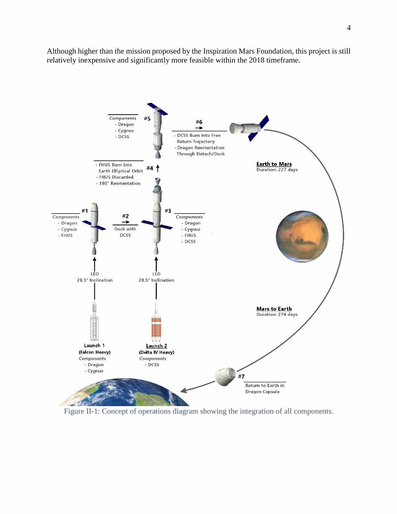
II. Concept of Operations The IMMORTAL mission architecture requires two launches. The first launch will utilize
the SpaceX Falcon Heavy rocket and will consist of the following
Dragon capsule that will carry the crew into space
Cygnus habitat module where the crew will spend most of the 501 day journey
Service module that holds life support systems for the crew
This launch carries significantly less payload than the estimated lift capacity of the Falcon
Heavy to Low Earth Orbit (LEO). As a result, the Falcon Heavy Upper Stage (FHUS) will have a
significant amount of propellant leftover at burnout. This stage will be retained to help perform
part of the trans-Mars injection (TMI) burn.
Shortly following this launch, a 4 m Delta Cryogenic Second Stage (DCSS) propulsion
module will be launched using a Delta IV Heavy. Subsequently, the DCSS will dock with the
Dragon-Cygnus assembly in LEO. After a series of checkouts, the FHUS will ignite and transfer
the assembly into a highly elliptical orbit around Earth. The spacecraft will then discard this stage
and reorient to perform the second half of the burn using the DCSS. The DCSS will burn at perigee
of the next orbit, setting the craft on its free return trajectory which will take the assembly to Mars.
After the DCSS stage is discarded, the Dragon capsule will detach from the top of the Cygnus
module and perform a maneuver similar to that required by the Apollo missions. This maneuver
will involve the Dragon capsule performing a 180 degree spin to move from its launch position to
the orientation for docking with the Cygnus habitat. The crew will then transfer over to the habitat
for the remainder of their journey. After 224 days, the Dragon-Cygnus vehicle containing the crew
will reach Mars and perform a flyby at an altitude of 100 km. Following this momentous
accomplishment, the crew will spend an additional 271 days in the habitat heading back to Earth
before transferring over to the Dragon capsule for Earth re-entry. This mission places a mass of
15,875 kg on this trajectory with an 11% margin for contingencies. The total budget amounts to
$1,493M USD, according to NASA’s Project Cost Estimating Capability (PCEC) framework.
4
Although higher than the mission proposed by the Inspiration Mars Foundation, this project is still
relatively inexpensive and significantly more feasible within the 2018 timeframe.
Figure II-1: Concept of operations diagram showing the integration of all components.

5
III. Launch Vehicles To satisfy the mission requirements, a total of two launches will be made. To confine the
mission to one launch, the Space Launch System (SLS) would be the only option for a payload
consisting of all mission components. The use of SLS Block I would present significant risk with
the first launch planned for December of 2017, well within the vicinity of the IMMORTAL launch
date [1]. The availability of this launch vehicle is uncertain due to potential delays or cancellations.
Similarly, the SLS Block IB is not expected to launch until 2021, which is outside of the mission
timeframe [2]. Alternatively, increasing the launch count to three total launches would introduce
unnecessarily complex orbital docking operations.
The choice of the SpaceX Dragon as the re-entry capsule necessitates the use of the Falcon
Heavy launch vehicle, which has a sufficient lift capacity to transport both the Dragon capsule and
the Cygnus habitat/service modules through a single launch with spare propellant for the transfer.
The large payload capacity and low launch cost of the Falcon Heavy make it a cost-effective choice
for this mission [3].
The second launch includes the 4-meter DCSS, which requires liquid hydrogen fueling.
The Falcon launch pad supports only RP-1 fueling, eliminating the Falcon Heavy as an option.
Consequently, the ULA’s Delta IV Heavy was selected for its payload capacity as well as its ease
of integration with the DCSS, which is a stage of the Delta IV series launch vehicles [4].
Table III-1: Launch Vehicle Trade Study
Launch
Vehicle
Launch
Site
Cost per Launch
(USD in millions)
Payload
Mass (kg) to
LEO
Inclination
28.5°
Cost per kilogram to
200km Inclination 28.5°
($/kg)
Estimated
Availability
Delta IV
Heavy
CCAFS,
VAFB
290 28,790 10,070 In Service
Falcon
Heavy
KSC,
VAFB
135 53,000 2,500 2014
Falcon 9 CCAFS,
VAFB
56.5 (as of 2013) 13,150 4,300 In Service
Atlas V
552
CCAFS,
VAFB
250 20,520 12,180 In Service
SLS Block
I
KSC 500 70,000 7,100 2017
SLS Block
IB
KSC ??? 118,000
2023

6
Figure III-1: Diagrams showing the location of all components within their payload fairings.
IV. Orbital Mechanics On January 1st 2018, SpaceX’s Falcon Heavy will carry the crewed Dragon capsule along
with the Cygnus habitat and service module to a circular Low Earth Orbit with an altitude around
200 km and a period of 90 minutes. Shortly after, a Delta IV Heavy launch will carry the DCSS to
LEO in order to dock with the habitat. In order to mitigate propellant boil-off and to minimize
astronaut downtime, the launches will need to occur in quick succession. This docking maneuver
will rely on highly developed technologies for docking that have been perfected throughout the
life of the International Space Station (ISS) as well as during other manned missions.
After assembly, leftover fuel in the FHUS will be burned first, imparting about 1.70 km/s
delta-v before being discarded. This will place the assembly into a highly elliptical orbit around
Earth with period 4 hours. It will reorient itself and upon reaching perigee the DCSS will perform
the TMI maneuver. An analysis of the capabilities of the Falcon Heavy and the Delta IV Heavy
shows that they are capable of performing such maneuvers [3] [4]. After the FHUS burn, the DCSS
will be required to impart 3.1 km/s into the habitat to perform the flyby. Calculations show that
the DCSS has 3.3 km/s delta-v available for the burn. The TMI maneuver was targeted using STK’s
Astrogator module in order to optimize C3. The method is based on similar methods used in the
IEEE Conference Feasibility Analysis [5]. Using these methods, the DCSS would need to leave
the Earth with a C3 of 39.0 (km/s)2.

7
Facilities on the ground will continuously assess the trajectory of the habitat to ensure it
was put onto the proper orbital trajectory, and that the habitat will be put onto the correct free-
return trajectory after the flyby, calculating any possible course corrections that would need to be
made. Over the course of the mission, there are multiple opportunities to perform Trajectory
Correction Maneuvers (TCM’s) if need be. Such maneuvers would be handled by attitude control
system aboard the service module, and would require as little as .5 m/s of delta-v. A TCM at
periaerion of at most 30 m/s would be the upper bound of possible course corrections. The habitat
would be in transit to Mars for 227 days, coming near the planet in Mid-August of 2018 [6]. The
flyby would bring the habitat within 100 miles of the Martian surface before Mars’ gravity would
swing the habitat on its return trajectory. The IMMORTAL habitat will spend a short time near
Mars during which detailed observations of the planet and its moons can be made. 274 days later
in Mid-May of 2019, the habitat will return to Earth, arriving with a velocity 14 km/s relative to
the Earth before entering Earth’s atmosphere. The total delta-v required from LEO to re-entry for
the mission, excepting any extraneous course corrections is 4.8 km/s.
Figure IV-1: STK Model displaying the orbital track of the flyby mission.
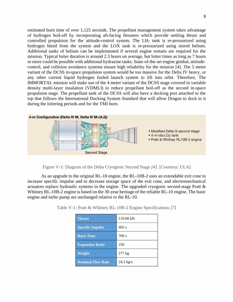
V. Propulsion There are two potential Delta-Cryogenic Second Stage (DCSS) configurations that are
worth considering. One is the 4-m version which is used on rockets such as the Delta IV M and
Delta IV M+. There is also the extended 5-m version which is used typically for larger rockets
such as the Delta IV H, or for when more propellant is needed on the Delta IV M or Delta IV M+.
The engine core for both configurations is the Pratt & Whitney RL10B-2 engine. A diagram of the
upper stage is listed below (Figure V-1) along with specifications for the engine (Table V-1). The
extended design is based on the smaller 4-m design. The major differences include a larger LOX
tank, specifically 0.5 m longer in length; as well as a larger LH2 tank, which has an enlarged tank
diameter of 5 m. The propellant load in this larger design has a capacity of 27,200 kg and an
8
estimated burn time of over 1,125 seconds. The propellant management system takes advantage
of hydrogen boil-off by incorporating aft-facing thrusters which provide settling thrust and
controlled propulsion for the attitude-control system. The LH2 tank is re-pressurized using
hydrogen bleed from the system and the LOX tank is re-pressurized using stored helium.
Additional tanks of helium can be implemented if several engine restarts are required for the
mission. Typical loiter duration is around 2.3 hours on average, but loiter times as long as 7 hours
or more could be possible with additional hydrazine tanks. State-of-the-art engine gimbal, attitude-
control, and collision avoidance systems ensure high reliability for the mission [4]. The 5 meter
variant of the DCSS in-space propulsion system would be too massive for the Delta IV heavy, or
any other current liquid hydrogen fueled launch system to lift into orbit. Therefore, The
IMMORTAL mission will make use of the 4 meter variant of the DCSS stage covered in variable
density multi-layer insulation (VDMLI) to reduce propellant boil-off as the second in-space
propulsion stage. The propellant tank of the DCSS will also have a docking port attached to the
top that follows the International Docking System Standard that will allow Dragon to dock to it
during the loitering periods and for the TMI burn.
Figure V-1: Diagram of the Delta Cryogenic Second Stage [4]. [Courtesy: ULA]
As an upgrade to the original RL-10 engine, the RL-10B-2 uses an extendable exit cone to
increase specific impulse and to decrease storage space of the exit cone, and electromechanical
actuators replace hydraulic systems in the engine. The upgraded cryogenic second-stage Pratt &
Whitney RL-10B-2 engine is based on the 30-year heritage of the reliable RL-10 engine. The basic
engine and turbo pump are unchanged relative to the RL-10.
Table V-1: Pratt & Whitney RL-10B-2 Engine Specifications [7]
Thrust 110.00 kN
Specific Impulse 465 s
Burn Time 700 s
Expansion Ratio 250
Weight 277 kg
Nominal Flow Rate 24.1 kg/s

9
Mixture Ratio 5.85 to 1
Dimensions (h x r) 4.14 m x 2.21 m
Propellants LOX & LH2
Status In production
Boil-off can cause a significant loss in propellant if the mission loiters for too long before
TMI and must therefore be considered heavily in mission design. Typical magnitudes of boil-off
rates for LH2 and LOX tend to be at a minimum of several 10-1 kg/hr and a maximum magnitude
of 101 kg/hr. These rates are largely affected by the external heat flux penetrating the propellant
and less to do with the total mass of the propellant. Therefore it is of utmost of importance to
minimize the effects from solar radiation and from the heat leaked of internal components in order
to reduce propellant boil-off [8].
When coasting times are low, boil-off is typically dealt with by implementing various
control techniques. Currently the system in place is the typical Cryogenic Fuel Management
System, which essentially maintains a low temperature in the propellant tank to prevent the
diffusion and destratification of liquid phase propellant by various means. The fuel management
system is typically designed with primary objectives including effective propellant storage with
minimal loss, vapor-free propellant distribution including the inlets and outlets, and a robust
control system which minimizes propellant settling.
Such a system will have various implications on the design, not only limited to the
propellant boil-off rates. A Cryogenic system can greatly reduce the propellant launch mass and
the on-orbit margins. Such a design even tackles the complex problem of propellant settling and
allows major system benefits by simplifying and optimizing the system architecture. There is
already a pre-existing design for the Cryogenic Management system, developed by Lockheed
Martin called the ICES (Integrated Common Evolved Storage) developed for the Centaur Upper
Stage, which revolves around these goals. Centaur uses the same RL-10 engine as the DCSS in-
space propulsion stage being used on this mission, so integration of the ICES or similar fuel
management systems should be fairly compatible with the DCSS systems. With minor
modifications such systems can even be implemented for long duration missions, such modified
systems are generally for significantly larger missions to the outer solar system [9]. Although the
propellant will be expended on a much sooner into the mission than these long duration mission
modifications would be intended for, aspects of the long duration solutions can certainly be
adopted in order to preserve fuel boil-off in general.

10
Figure V-2: Subsystem interfaces for a typical Cryogenic Fuel Management System.
The fuel management system outlined above has limitations, in that the system is not
designed for long duration missions. Because the mission’s main propulsive maneuvers will be
done early on in the mission duration, this is not a problem. However, as mentioned before, the
fact that the LOX/LH2 tank will loiter in space for up to 24 hours is important to take into
consideration, as well as the time the propellant tank will take to reach the initial payload in the
subsequent launch; especially when considering the higher boil-off rate of LH2. Design
modifications can very easily improve the existing design to the mission objective particularly by
implementing improved passive storage.
Much can be learned about the boil-off behavior of the DCSS by looking at a very similar
upper stage, the Centaur. The Centaur tank is a very good example to compare the DCSS; not only
are the engines the same but the tanks are approximately the same size, and as mentioned before,
the primary contributing factor to boil-off is the thermal influence of the surrounding environment,
which is assumed to be very similar for the Centaur and DCSS in orbit. The boil-off rates for the
Centaur propulsion system has been examined extensively on several occasion by ULA [10]. They
have found that the Centaur has typical boil-off rates of 1-4.8% per day. The variation in the boil-
off rate here was based on different degrees of heat flux entering the controlled propellant tank
and the type of insulation used. This can become problematic if the loiter time becomes too high
while waiting for TMI. Minimizing boil-off is critical, since launching excess propellant which
will ultimately diffuse is wasteful of the limited payload mass, and when considering the length of
such an interplanetary mission, payload mass is extremely critical. Furthermore, since the mission
involves launching two separate payloads a system to decrease propellant loss in the first launch
which will have very large loiter times is necessary.
Lockheed Martin, in association with ULA has presented various boil-off rates for different
operation conditions for LH2 and LOX tanks in the Centaur Upper stage. These values were
reconstructed from post-flight measurements obtained from the tank heating system.

11
Table V-2: LOX Boil-Off Rate for Two Centaur Tank Designs
Oxygen Boil-Off Hydrogen Boil-Off
Tank Design TC-15 TC-11 TC-15 TC-11
Tank
Insulation
3 Layer Radiation
Shield
3 Layer Radiation
Shield
3 Layer Radiation
Shield
3 Layer Radiation
Shield
Total Heat
Flux
615 Watts 381 Watts 733 Watts 909 Watts
Boil-off Per
Day
1.5% 1.0% 4.1% 5.1%
Table V-3: LH2 and LO2 Total Propellant Boil-Off Rates for Two Centaur Tank Designs
TC-15 TC-11
Propellant LOX LH2 LOX LH2
Single Prop. Boil-Off Rate 1.5% 4.1% 1.0% 5.1%
Total System Boil-Off Rate 2% - 1.6% -
The boil-off rates from the above study agree with the previous estimations of boil-off
rates. The Heat Flux values of approximately 733 Watts is a reasonable value for the design
parameter. As mentioned before the Centaur boil-off rates will be sufficient to do preliminary
calculations of propellant losses for the mission. Still, a conservative estimate would be preferred
for calculating the worst case scenario, and the largest reasonable boil-off rate values will be
chosen to proceed with the estimation of propellant loss. As such it will be assumed that the total
system boil-off rate will be 2.0% and LOX tank boil-off rate to be 1.5%. The total system boil-off
rate is the total mass of LOX and LH2 lost as a fraction of the total launch propellant mass per day.
The propellant loss will be a function of the boil-off rate, the amount of time spent loitering,
and the total mass of propellant during launch. In terms of the time spent loitering in orbit the
difference between the initial launch which uses RP-1 and LOX, and the second launch which uses
LH2 and LOX launch will be approximately one day in the worst case scenario. The SpaceX launch
will come from pad 39A at Cape Canaveral and ULA will launch the Delta IV Heavy. Assuming
a launch to orbital docking time of 4 hours for the second payload the total time spent loitering by
the initial oxygen tank can be estimated to be 28 hours and the time for the second LH2/LOX tank
to be 4 hours. Note the RP-1 boil-off is not considered since it non-cryogenic and will have
insignificant boil-off when compared to LH2 and LOX. The initial RP-1/LOX will contain 30,300
kg of propellant mass once it is in orbit and the secondary launch will contain 20,410 kg of launch
propellant LH2/LOX. The Oxidizer/Fuel Ratio of RP-1/LOX is 2.77 and thus it can be determined
that the LOX mass in the initial launch is 22,263 kg.

12
Table V-4: Propellant loss summary with standard fuel management
Propellant Mass Boil-Off Rate Loitering Time Propellant Lost
Falcon LOX Tank 22,263 kg 1.5% per day 28 hours 389 kg
DCSS LOX/LH2 20,410 kg 2.0% per day 4 hours 68 kg
These values with the above conventional cryogenic solutions lead to noticeably large
propellant loss for the mission as seen from the summary chart above. 389 kg is a significant
portion of the payload mass and thus a novel solution to greatly improve the boil-off loss is
required. The simplest solution will be in the form of passive-storage improvements, the most
promising of which is the newly developed VDMLI material.
As mentioned the greatest contributing factor to boil-off is the influence of the heat flux
from the surrounding environment. If better thermal insulation is implemented on the propellant
tanks, propellant loss can be significantly minimized, without adding excessive weight to the
spacecraft. The current standard Multiple Layer Insulation has a new design improvement referred
to as VDMLI. Variable density MLI is a type of insulation material that optimizes the radiation
insulation capability relative to standard MLI by having a gradient of spacing in between each of
the layers of insulation. The concept is to space the inner layers (closer to the cold tank wall)
further apart than the outer layers (closer to the warm radiation region) where the bulk of the
radiation heat transfer penetrates. The spaces are held fast by bumped ridges that keep the layers
spaced. Thus for a given insulation mass the design achieves an optimal insulation via this variable
spacing. The drawback with the technique is the slightly larger volume due to the larger spacing.
Figure V-3: Cross section of VDMLI demonstrating spacing gradient between layers.
Lockheed Martin has also conducted studies and projections of potential design
improvements for their Centaur upper stage using this VDMLI instead of the standard MLI used
currently [8]. The VDMLI can greatly reduce the amount of heat flux entering the tank and
therefore greatly reduce boil-off and save propellant mass that would otherwise have been

13
launched and lost. Take into consideration the VDMLI heating values and boil-off values seen
below:
Table V-5: Projections of LOX and LH2 Boil-Off Rates with VDMLI Implemented
LOX LH2
Heat Flux 950 Btu/hr 1350 Btu/hr
Single Species Boil-Off per day 0.7 % 2.4 %
Total Prop. Boil-Off per day 1.0 %
As can be seen, the previously estimated LH2/LOX and LOX boil-off rates were almost
twice as large as the estimated rates with VDMLI implemented. Using improvements to lower
these boil-off rates in the mission design will therefore create significant improvements in limiting
propellant loss.
Table V-6: Propellant Loss Summary with Standard Fuel Management System + VDMLI
Propellant Mass Boil-Off Rate Loitering Time Propellant Lost
Falcon LOX Tank 22,263 kg 0.7% per day 28 hours 182 kg
DCSS LOX/LH2 20,410 kg 1.0 % per day 4 hours 34 kg
The typical weight of standard MLI is approximately 56 kg for the dimensions of an upper
stage tank. The weight for the VDMLI insulation of the same tank would be 57 kg. For such a
marginal cost in dry mass, the propellant loss can be greatly reduced and approximately 241 kg
less of propellant mass launched if VDMLI is implemented on both the RP-1/LOX tank and the
LH2/LOX tanks of both in-space propulsion systems utilized on the mission.
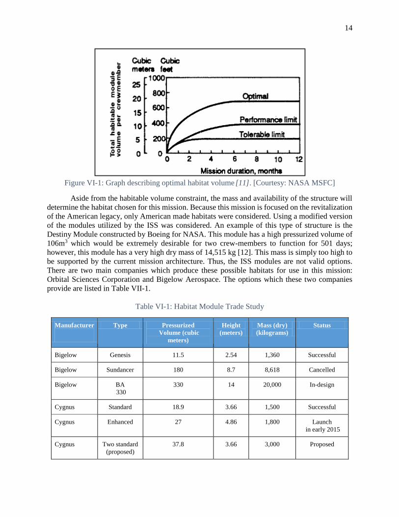
VI. Habitat Design This two person fly-by mission of Mars will require sufficient space for the astronauts to
live for just over 500 days. In a study published by the NASA Johnson Space Center Figure VII-
1, the total habitable volume per crewmember was calculated for tolerable, performance, and
optimal limits. Based on chart, the needed volume per person is 5m3 for tolerable, 10.5m3 for
performance, and 19m3 for optimal. Because of the length of this mission, the goal is to construct
a habitat between the performance and optimal range, that being 21m3 to 38m3.
14
Figure VI-1: Graph describing optimal habitat volume [11]. [Courtesy: NASA MSFC]
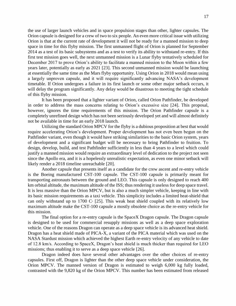
Aside from the habitable volume constraint, the mass and availability of the structure will
determine the habitat chosen for this mission. Because this mission is focused on the revitalization
of the American legacy, only American made habitats were considered. Using a modified version
of the modules utilized by the ISS was considered. An example of this type of structure is the
Destiny Module constructed by Boeing for NASA. This module has a high pressurized volume of
106m3 which would be extremely desirable for two crew-members to function for 501 days;
however, this module has a very high dry mass of 14,515 kg [12]. This mass is simply too high to
be supported by the current mission architecture. Thus, the ISS modules are not valid options.
There are two main companies which produce these possible habitats for use in this mission:
Orbital Sciences Corporation and Bigelow Aerospace. The options which these two companies
provide are listed in Table VII-1.
Table VI-1: Habitat Module Trade Study
Manufacturer
Type Pressurized
Volume (cubic
meters)
Height
(meters)
Mass (dry)
(kilograms)
Status
Bigelow Genesis 11.5 2.54 1,360 Successful
Bigelow Sundancer 180 8.7 8,618 Cancelled
Bigelow BA
330
330 14 20,000 In-design
Cygnus Standard 18.9 3.66 1,500 Successful
Cygnus Enhanced 27 4.86 1,800 Launch
in early 2015
Cygnus Two standard
(proposed)
37.8 3.66 3,000 Proposed

15
Cygnus Super
enhanced
(proposed)
35 6.06 2,300 Final Design
selected
(proposed)
To date, Bigelow Aerospace has four concepts for in space habitats. All of Bigelow’s
habitats are modules that inflate upon reaching orbit, allowing for a lower structural mass as well
as a smaller launch package. This concept presents an issue of finding enough space in the pre-
inflated structure to store all of the supplies needed for this mission. In addition, the crew would
be required to setup their habitat upon reaching orbit, taking up valuable crew time. The Bigelow
Genesis I and II modules were the first two habitats constructed by Bigelow, and they are the only
ones developed by Bigelow to ever fly in space. Despite being lightweight, this habitat is simply
has too little volume (11.5m3) to sustain the two crew-members for 501 days [13]. The next concept
proposed by Bigelow was the Sundancer model. This design concept had a large pressurized
volume of 180m3 with a mass of 8618 kg. The module would be too heavy to be used as a part of
any realistic Inspiration Mars architecture and was also cancelled by Bigelow in July of 2011; thus,
it is not a viable option for this mission [14]. Bigelow’s next concept, the BA-330, has a pressurized
volume larger than ever would be needed for a two person, and, consequently, the proposed mass
for this structure heavily exceeds the limitations of the mission architecture [15]. In the end, all of
the Bigelow concepts do not meet this mission’s requirements.
Currently there are two models of Cygnus designed: Standard and Enhanced. Both modules
have a low mass which fits into the mission architecture. The standard has already had two
successful missions which involved delivering pressurized cargo to the ISS. The Enhanced model
will be tested in early 2015. The Enhanced module is effectively a Standard module extended from
its original size by increasing the height of the module by 1.2m. This increased the pressurized
volume from about 18.9 cubic meters to 27 cubic meters. To support these increased dimensions
the service module has been made lighter and more efficient and the propulsion has been boosted
[16]. The Standard module’s pressurized volume would lead to an incredibly small living quarters
for this two-person crew to survive for 501 days. The Enhanced module has a pressurized volume
larger than the minimum volume requirement; however, not all of the pressurized volume is usable
for habitable volume. Based on calculations NASA used for the ISS, the habitable volume of the
Enhanced module would drop below the minimum volume requirement of 21 m3 [17].
Consequently, the Enhanced section is not a feasible option for this mission.
In order to facilitate the habitable volume needs of the crew, a modified Cygnus capsule
architecture is necessary. The first proposal calls for using two Cygnus Standard modules which
would dock together in orbit via conjoining module which would be need to be researched and
developed. Despite doubling the available habitable volume of a Standard module, this proposal
would require complex orbital assembly to ensure proper docking of the two Standard modules
which is undesirable. Instead, a Cygnus Super-Enhanced is proposed. This module would be
Standard module stretched to 2.4m instead of the 1.2 m stretch applied to the basic Enhanced
Module. The proposed module would have a mass of 2,300 kg with a total of height 6.06 m. This
proposal avoids simply doubling the mass of the Standard module by only extending the center of
the Standard module, such that there are still only the two end caps, and utilizing only a single
service module to house all necessary support systems. The Super-Enhanced module would have
a PCM with the standard 3.07 m diameter and a total pressurized volume of 35 cubic meters [18].
Once again, based on the calculations used by NASA for ISS and once an estimated 5 m3 usable
storage volume onboard the Dragon capsule has been factored in, a total habitable volume of 24.4

16
m3 is obtained. This volume is within the acceptable range of habitable volume in order for the
two-person crew to function efficiently, and the mass of this proposal is possible with the current
mission architecture and chosen launch vehicles.
VII. Re-entry Technologies The most critical part of the entire mission is the re-entry phase. If the crew fails to re-enter
safely, the mission will have been a catastrophic failure. As such, it is the primary driving force
for the design of the entire mission. A return capsule must be chosen that can withstand the re-
entry heating that will be experienced coming back into the Earth’s atmosphere. Based on
simulations, the re-entry vehicles would need to handle speeds of 14 km/s, potentially up to as
much as 14.2 km/s. If it cannot withstand these speeds, the capsule will have to be slowed to a
survivable velocity before re-entering the atmosphere. This will significantly increase the size of
the launch vehicles and in-space propulsion stages. Once the capsule and re-entry method are
determined, launch vehicle architecture can be chosen to support the rest of the mission.
No matter what capsule is chosen, there are other critical issues that must be addressed.
This mission will require re-entry velocities of up to 14.2 km/s, and to date, the fastest re-entry
that has ever been achieved was 12.8 km/s, achieved by the Stardust sample return capsule [19].
No re-entry system has been tested to velocities higher than that in practice, and facilities do not
currently exist that can simulate the re-entry velocities and temperatures required. In order to
properly test the capabilities of the heat shield to the required extremes, existing facilities will have
to upgraded or new facilities constructed, which will take time and will cost a significant sum of
money. There are however, currently plans to upgrade existing facilities; this will offset the cost
of development and construction of the new facility [20].
For the choice of re-entry vehicle, four different options will be considered and are
presented in the table below:
Table VII-1: Re-entry Capsule Selection Matrix
Vehicle Heat Shield Material Plausible Manned Launch Date
Orion MPCV AVCOAT 2021
Orion Pathfinder AVCOAT 2023
CST-100 Boeing Lightweight Ablator 2016
Dragon PICA-X 2015
The Orion MPCV is one of the more promising candidates for the re-entry capsule. It is
meant to be used for deep-space and interplanetary missions, it will be meant to handle extreme
re-entry velocities and long duration missions outside of Earth’s sphere of influence. Orion’s heat
shield will be made of a reformulation of AVCOAT, the material that was proven on the Apollo
missions to withstand a re-entry velocity of 11 km/s [21].
Even though this capsule will be able to withstand high re-entry speeds, it is a very massive
capsule. Orion is expected to have a mass of 9,820 kg fully loaded [22]. As a result, it will require
17
the use of larger launch vehicles and in space propulsion stages than other, lighter capsules. The
Orion capsule is designed for a crew of two to six people. An even more critical issue with utilizing
Orion is that at the current rate of development it will not be ready for a manned mission to deep
space in time for this flyby mission. The first unmanned flight of Orion is planned for September
2014 as a test of its basic subsystems and as a test to verify its ability to withstand re-entry. If this
first test mission goes well, the next unmanned mission is a Lunar flyby tentatively scheduled for
December 2017 to prove Orion’s ability to facilitate a manned mission to the Moon within a few
years later, potentially as early as 2021 [23]. This second unmanned mission would be launching
at essentially the same time as the Mars flyby opportunity. Using Orion in 2018 would mean using
a largely unproven capsule, and it will require significantly advancing NASA’s development
timetable. If Orion undergoes a failure in its first launch or some other major setback occurs, it
will delay the program significantly. Any delay would be disastrous to meeting the tight schedule
of this flyby mission.
It has been proposed that a lighter variant of Orion, called Orion Pathfinder, be developed
in order to address the mass concerns relating to Orion’s excessive size [24]. This proposal,
however, ignores the time requirements of this mission. The Orion Pathfinder capsule is a
completely unrefined design which has not been seriously developed yet and will almost definitely
not be available in time for an early 2018 launch.
Utilizing the standard Orion MPCV for the flyby is a dubious proposition at best that would
require accelerating Orion’s development. Proper development has not even been begun on the
Pathfinder variant, even though it would have striking similarities to the basic Orion system, years
of development and a significant budget will be necessary to bring Pathfinder to fruition. To
design, develop, build, and test Pathfinder sufficiently in less than 4 years to a level which could
justify a manned mission would require an extraordinary level of dedication to the project not seen
since the Apollo era, and it is a hopelessly unrealistic expectation, as even one minor setback will
likely render a 2018 timeline unreachable [20].
Another capsule that presents itself as a candidate for the crew ascent and re-entry vehicle
is the Boeing manufactured CST-100 capsule. The CST-100 capsule is primarily meant for
transporting astronauts between the ground and LEO. This capsule is only designed to reach 400
km orbital altitude, the maximum altitude of the ISS; thus rendering it useless for deep space travel.
It is less massive than the Orion MPCV, but is also a much simpler vehicle, keeping in line with
its basic mission requirements as a taxi vehicle. This simplicity includes a limited heat-shield that
can only withstand up to 1700 Co [25]. This weak heat shield coupled with its relatively low
maximum altitude make the CST-100 capsule a mostly obsolete choice as the re-entry vehicle for
this mission.
The final option for a re-entry capsule is the SpaceX Dragon capsule. The Dragon capsule
is designed to be used for commercial resupply missions as well as a deep space exploration
vehicle. One of the reasons Dragon can operate as a deep space vehicle is its advanced heat shield.
Dragon has a heat shield made of PICA-X, a variant of the PICA material which was used on the
NASA Stardust mission which achieved the highest Earth re-entry velocity of any vehicle to date
of 12.8 km/s. According to SpaceX, Dragon’s heat shield is much thicker than required for LEO
missions; thus enabling it to serve as a deep space vehicle [26].
Dragon indeed does have several other advantages over the other choices of re-entry
capsules. First off, Dragon is lighter than the other deep space vehicle under consideration, the
Orion MPCV. The manned version of Dragon is estimated to weigh 6,000 kg fully loaded,
contrasted with the 9,820 kg of the Orion MPCV. This number has been estimated from released

18
data about the capsule by SpaceX since they have not released the final number yet for the manned
version of Dragon. The unmanned version currently has a 4,200 kg dry mass, is a reasonable
estimate based on the proposed changes [5]. Dragon is significantly lighter than Orion making the
more economical choice for a two person fly-by mission; consequently, this makes Dragon a clear
choice over Orion. As stated above, Dragon is intended to serve as both a commercial resupply
vehicle and deep space transportation vehicle. This simple fact it designed to go outside of LEO
makes it a clear choice over Boeing’s CST-100 capsule.
Overall, the Dragon capsule best suits the needs of this mission. It is relatively lightweight
at 6,000 kg. Its heat shield, constructed of PICA-X, has been proven to withstand re-entry at 12.8
km/s which is the highest ever successful re-entry speed recorded [27]. Additionally, Dragon has
sufficient space for a two person re-entry mission since it is designed to hold up to seven people.
Additionally, Dragon’s operational life is rated to be up to two years which is less than the overall
time of this fly-by mission [26]. In conclusion, the SpaceX Dragon capsule is the best suited for
this mission.
Before the Dragon capsule can be used as the re-entry capsule, it is necessary to ensure that
capsule can survive the high speed re-entry at 14.2 km/s. There are three main ways that this can
be done. First off, the Dragon capsule as it is manufactured by SpaceX with no modifications can
be used as a viable option, because the company’s technical specifications which state that the
Dragon Capsule can withstand standard Mars return trip re-entry speeds [26]. Secondly, a simple
option to bolster the standard heat shield of Dragon would be to simply make it thicker to be more
resilient to account for the increased Mars return velocity. The final option would be to add a retro-
propulsive rocket motor to Dragon to slow the vehicle down to 12.8 km/s or less as it hits the
atmosphere.
If it were determined that the Dragon heat shield cannot withstand the re-entry speeds of
up to 14.2 km/s, the re-entry velocity of Dragon will have to be lowered to a velocity that it will
survive re-entry. Dragon’s PICA-X heat shield material was based off of the NASA developed
PICA material which was used on the Stardust probe which was proven to a re-entry speed of 12.8
km/s [27]. This 12.8 km/s consequently represents the velocity threshold to be targeted for retro-
propulsion until a better number is identified via testing the heat shield material.
Additional mass margins for the mission will be put towards adding a thicker heat shield if
it is determined that the basic Dragon heat shield is not sufficient for Earth re-entry at the required
velocities; as well as there will be additional budgets set aside to pay for the development and
testing of said heat shield. However, there currently are no facilities that can test re-entry speeds
of 14.2 km/s. There are plans for test facility upgrades, but they will only be to sufficient to
simulate a heating level of 2000 W/cm2, which represents be a significant improvement to the
current 1400 W/cm2 [20]. In theory, this increase will be enough to test the improved heat shield.
Once this facility operational, testing would be paid for in order to determine how much thicker of
a heat shield was needed than the stock thickness.
The ideal scenario for adding a retro-propulsive rocket motor would be in the case where
only the crew and the most essential supplies remained in the capsule, and only a minimal amount
of RCS propellant remaining. If a STAR 63F solid rocket motor were attached to Dragon for the
purposes of doing a retro-propulsive maneuver to slow it for re-entry, based on our calculations,
an additional 1700 m/s of delta-V can be acquired assuming a nearly empty Dragon mass of 5000
kg [28]. This would add an additional 4600 kg of mass to the re-entry unit of the spacecraft, and
bring the spacecraft velocity down to 12.3-12.5 km/s depending on the exact re-entry velocity of
the craft, well under the 12.8 km/s threshold. Based on our calculations, this additional mass will

19
result in an increase in the mass of the in-space propulsion stage of upwards of 30%, representing
a corresponding increase in launch vehicle size. In order to accommodate the increase in payload
to orbit required, the mission will likely require a third launch, or require the utilization of SLS as
a heavy-lift launch vehicle. This would further increase the cost and complexity of the mission
significantly. The preferred option would be to increase the thickness of the Dragon heat shield so
that it will be able to withstand the re-entry heating that will be experienced at unmitigated
velocities, as it represents an option that is operationally much simpler and much cheaper than
implementing retro-propulsion. For this reason, retro-propulsion will be left as a last resort, in the
event of a failure to prove or develop a heat shield sufficient for the mission.
Overall, simply making the heat shield thicker on the Dragon Capsule outweighs the cost
of using retro-rockets because of the mass and economic savings. The driving force behind this
decision is that SpaceX’s technical specifications for the Dragon Capsule rate it to survive
traditional Mars return velocities. Since this mission will be returning with a non-standard Mars
return velocity, it will be necessary to increase the thickness of the heat shield which will be
determined through testing at the updated facility mentioned above. Based on rough calculations,
a 2-2.5 times the stock thickness of Dragon should be acceptable from this mission factoring in a
reasonable safety factor.
In the final days of the mission, as the re-entry capsule nears Earth, all non-essential
supplies and equipment will be moved from the capsule to the habitat as a lighter re-entry capsule
will be slowed down more effectively during re-entry. The habitat will then detach from the
capsule two hours before entry begins, and the capsule will orient itself for re-entry. Dragon will
then undergo re-entry through Earth’s atmosphere at 14 km/s to bring the capsule safely back to
Earth. The parachute landing systems of Dragon will be utilized as the primary landing system due
to the simplicity and reliability that they offer, rather than the propulsive landing system; the fuel
for the propulsive landing system will be used both for attitude control and for midflight course
corrections. Once the capsule has slowed sufficiently and reached 13.7 km altitude the drogue
parachutes will deploy, followed by the main parachutes at around 3 km altitude [29]. A water
landing is preferable to a land touchdown if orbital adjustments are able provide for it, but land
touchdown is acceptable if there is no viable alternative, as just making re-entry is of greater
concern than making a specific landing area for the purposes of this mission. Any attempt to target
a landing site will have to be done during the course corrections that will initially be quite sensitive
to the corrections, and will become increasingly difficult to change as the end of the mission
approaches and the re-entry corridor restricts possible trajectories.
VIII. Power The power storage and generation systems for the mission will be largely localized in the
Cygnus habitat’s service module. The mission will utilize solar power, along with batteries to
cover any possible power shortages due to shadowing or any other technical issues. Nuclear power
was not considered due to timeline constraints and a lack of in space development for these
technologies, and it was not considered necessary, as this mission is close enough to the Sun that
solar power is still cost and mass effective at the maximum mission aphelion distance.
The SpaceX Dragon capsule will utilize Lithium-polymer batteries for its various power
requirements during launch and flight. The solar arrays on the connected Cygnus habitat module
will provide power to the Dragon capsule whilst in orbit, as the Dragon trunk will not be used.

20
The default Cygnus habitat module will produce around 3.5 kW of solar power at 1 AU
distance from the sun, with the stock design on the Cygnus capsule [30]. Additional solar arrays
will be necessary, as the power requirements for a long-term manned mission are higher than those
required for low-Earth orbit loitering. In addition, Mars will be at a distance of 1.39 AU at mission
aphelion, very close to Mars perihelion, which means that the solar radiation levels there would be
52% of normal Earth levels. The solar panels will only be able to produce about half the amount
of power that is available in low-Earth orbit; less than at any other point in the mission. This means
the solar panels must be sized according to the amount of peak power that would be required at
the mission aphelion. Excess power will be used to charge on-board batteries, however, since
shadowing will be minimal, the rest of the excess power will have to be shunted at the arrays.
Ni/H2 batteries will be used as primary batteries in the habitat for times when shadowing is present
or if the power system cannot otherwise cope with power demand. 28 VDC and 120 VDC and
other electronics, similar to those used on the ISS, will be used for all systems of the IMMORTAL
mission [31].
NASA predicts a power requirement of 18kW for a 500-day habitat configuration based
off of ISS modules, which requires approximately 36 m2 of solar arrays at 60 W/kg [32]. Based on
the habitat’s much smaller volume, 10 kW will be sufficient to power all spacecraft components
in this mission, which requires approximately 20 m2 of solar arrays at 60 W/kg. However, since
available sunlight at a Martian distance from the sun is about half, a total solar array area of 40 m2
will be needed.
The solar arrays will be fitted with Multi-junction Inverted Metamorphic (IMM) Solar
Cells [32]. The technology readiness level of such solar arrays is 8. Lighter ATK Ultraflex solar
arrays could be used to provide additional mass savings if they prove to be ready by launch date,
but at the date of this writing, they are at a technology readiness level of 6 [33]. No additional
funding will be provided within the scope of the IMMORTAL architecture for these panels, but
should they be developed independently they could be substituted. The entire power system with
standard solar panels will have an approximate mass of 445 kg, including wiring, solar arrays, and
batteries.
IX. Communications By examining the current technologies in development and available, the final technology
choices have been made regarding the communications equipment.
Table IX-1: Communication Trade Study [34]
Infrastructure
Requirements Distance Data Rate
Top Technology
Choice TRL Final Technology Used TRL
Mars Low Orbit to
Mars Orbiters ~400 km 10 Mbps Optical 4 UHF 9
Mars Orbiters to
Earth-Sun, L3, L4
Relay Link ~2.5 AU 100 Mbps Optical 4 UHF 9
Sun, L3, L4 to
Earth Orbit/Ground 1 AU 100 Mbps Optical 4 X-band 9
Emergency Coms.
High Grain 2.5 AU 10 Mbps X-band 9 X-band 9
Emergency Coms.
Low Grain 2.5 AU 1 Mbps Ka-band 9 Ka-band 9

21
Data will be transmitted over three different antennas: A high-gain antenna to handle the
high rate communication directly to Earth or via DSN. It has to be able to “aim” itself to within 2-
3 degrees of its target to uplink and downlink data. A UHF software designed radio will be used
to send large quantities of data to the DSN for the fastest communication with Earth. The UHF
will be the primary form of communication for the spacecraft. A low gain antenna will
continuously communicate with other spacecraft and satellites as part of the DSN. The low gain
antenna can only handle low data rates so it will be primarily used to receive data.
The data rates needed for communication between a spacecraft carrying humans and Earth
range between 1 Mbps and 100 Mbps, and sometimes even greater and need to be transmitted with
Ultra-High Frequency (UHF) relay and X band technology. The low gain antenna will have a low
data rate, around 1 Mbps, and the UHF will have speeds of around 150 Mbps. Data will primarily
be transmitted through the Deep Space Network (DSN) along the bidirectional backbone data relay
and secondarily through direct communication with antennas on Earth.
The spacecraft will also be equipped with a transponder. The transponder will have a
transmitter to generate the tone and radio frequency called a carrier wave to be amplified by the
antennas mention above. The receiver in the transponder will take the incoming radio signals or
uplinks and convert them into a perceptible form.
When the controlling body wants to communicate with the spacecraft directly or indirectly
through the DSN it will use the low gain antenna to determine the exact location and orientation
of the spacecraft and will then use that information to position the high gain antenna to
communicate with the satellite via the DSN [35].
X. Attitude Control and Navigation Throughout the duration of the mission, it is critical that the module is able to maintain
heading and bearing in the vast emptiness of space. Due to the nature of the mission, being a single
burn, free-return trajectory, makes it imperative that there be no flaws in the implementation of the
Reaction Control System (RCS) or navigational aids.
The RCS package which designed for this mission incorporates data collected from a pair
of Inertial Measurement Units (IMU), in order to calculate vehicle position and orientation.
However, due to the nature of IMUs, which rely on a combination of gyroscopes and
accelerometers to estimate position through successive calculation based on elapsed time and
spacecraft velocity and heading, the mission will also employ dual Solid State Star Trackers (SS),
which utilize star maps to detect the attitude of the craft, the data from which is then used to correct
for compounded IMU error [36]. These sensors should be mounted so as to allow for the largest
field of view possible, which will help to further reduce uncertainty in calculation. The last
navigational tools that the IMMORTAL mission will include are a Sun Sensor, which simply
locates the position of the Sun relative to the vehicle, for added accuracy in attitude estimation and
therefore increased precision in position calculation by the onboard flight computer, as well as a
Horizon Sensor, which will be used to further minimize error upon final approach to Earth for re-
entry, perhaps the most critical part of the mission.
In addition to these navigational aids, the module will employ two pairs of 3 Aerojet MR-
107V hydrazine thrusters, configured to provide omnidirectional attitude control without
imparting a translation to the vehicle. These 220N thrusters will provide the necessary impulse for
effective attitude control and trajectory manipulation throughout the mission, to ensure that the
spacecraft does not deviate from the flight plan [37]. For further precision, two sets of momentum

22
disks will be used, also arranged to provide 3-axis control, as these disks can create slight attitude
changes due to their small mass compared to that of the vehicle itself.
The Attitude Control & Navigation system includes several redundancies to protect against
the loss of vehicle maneuverability and the degradation of accuracy in positioning. Such situations
would prove catastrophic for mission success, since without fuel for a return burn, crew recovery
will be impossible unless accurate headings are maintained throughout the duration of the mission.
The seamless integration of these sensors and actuators will allow for slight changes in
attitude to be imparted to the vehicle during the 7 predefined TCM windows, which are outlined
in Table XI-1, shown below:
Table X-1: Trajectory Correction Maneuvers
Maneuver TCM Window Purpose
TCM-1 Days 15-20 Place vehicle on Mars fly-by trajectory
TCM-2 Days 110-115 Correct for TCM-1 execution errors
TCM-3 Days 190-195 Further corrections, if necessary
TCM-4 Day 225 Align vehicle for optimal free-return trajectory
TCM-5 Days 300-305 Return trajectory adjustment
TCM-6 Days 400-405 Correct for TCM-5 execution errors
TCM-7 Day 499 Final vehicle alignment for orbital insertion before re-entry
The initial launches of the Habitat and Propulsive Stage provides a unique challenge insofar
as the two modules must dock before continuing towards Mars. In order to complete this maneuver,
the propulsive stage will provide positional data from its onboard computers to the Cygnus module
in real-time, to facilitate the docking procedure between the two.
As the craft completes the initial burn before entering the cruise phase of the mission, it
must maintain a heading which will ensure that the propulsive stage does not strike Mars, as both
the stage and habitat will continue in the same direction after separation. Since the propulsive stage
will not have been decontaminated, it must be guaranteed that foreign microbes are not introduced
into the Mars atmosphere according to planetary protection protocols TCM-1 will then be used to
alter the course of the module to the planned fly-by route [38].
Through the implementation of the above systems, the IMMORTAL mission will find no
issue in executing its fly-by maneuver past Mars on day 227, and then continuing on to complete
its 501-day traverse of local space following re-entry upon arrival back at Earth.
XI. Environmental Control and Life Support System The purpose of the ECLS systems is to regenerate air, water, and food in a manner that
minimizes overall logistical burdens, and minimize demands on space habitat resources while
promoting self-sufficiency and ensuring habitability. It will designed to ensure maximum
redundancy as well as ease of access for repair in the case of any failure. The ECLS is responsible

23
for the effective environmental control and monitoring as well as waste management and water
recovery. It does all this while still providing for in situ maintenance. The ECLS will use closed
loop subsystems to maximize efficiency. As the IMMORTAL architecture does not allow for any
extra vehicular activity (EVA), all critical sections of the ECLS system must be serviceable from
within the crewed space. Most of these systems will be located inside the service module, but
access to them should be incorporated into the design of the modified Cygnus.
The Water Recovery and Management system is responsible for the physicochemical
systems used to increase efficiency and decrease cost of water recovery. Its purpose is to reduce
the Equivalent System Mass of water recovery subsystems and integrated systems while providing
for and supporting long duration integrated life support systems. The WRM is divided into two
separate collection and distribution loops. One is used to recover condensate to drinkable standards
for crew consumption, and the other is used to recover waste hygiene water back to hygiene
standards for crew bathing and equipment use. Crew urine is collected and processed separately
through distillation and then added to the waste collection side of the Hygiene Loop. The resulting
water of the WRS meets the highest standards for potable use while also playing a crucial role in
life support systems mainly feeding the IMMORTAL habitat’s oxygen generator which works off
of electrolysis and the Sabatier method. The Water Recovery and Management system for the
IMMORTAL habitat will have a total system mass of 675 kg, including spares for components
that are likely to fail. This number is in addition to the 1225 kg of water that will be kept on board
for fueling the oxygen generators, the WRS, and the ATCS water coolant loops.
The main purpose of the Air Revitalization System is to control the relative humidity of
the cabin and keep it between 30% and 75%, provide cooling to the IMMORTAL habitat’s cabin
compartment while monitoring temperature and ventilation, and maintaining carbon dioxide and
carbon monoxide at nontoxic levels. The Air Revitalization Systems incorporate water coolant
loops, cabin loops, and pressure controls to have the habitat’s two person crew atmospheric habitat
safe and ventilated. The habitat will utilize current technologies already aboard the ISS Destiny
module including several removal techniques for separating CO2 such as permeable membranes,
liquid amine, adsorbents, and absorbents. These processes efficiently contain and entrap carbon
dioxide and transport it around the module. The technologies going to be used on the IMMORTAL
include the Carbon Dioxide Removal Assembly (CDRA) [39]. The CDRA on the IMMORTAL
will utilize four beds each with a CO2 sorbent bed. The IMMORTAL will utilize a closed loop
CDRA system which could selectively remove carbon dioxide from the cabin air supply and
reroute it to a carbon dioxide reduction system. There the oxygen will be recovered reducing the
byproducts. The total weight of the CDRA and the Air Revitalization System will be reduced due
to the two person cabin.
The Waste Hygiene Compartment (WHC) is responsible for the collection of waste, its
processing and recovery of water, minerals and oxygen from organic trash and biological waste of
the crew. It also is responsible for odor control and hygiene maintenance in the spacecraft.
Trash must be collected, compacted, stabilized and stored such that it is harmless and at the same
time performs certain useful functions. An example is the case of the waste management aboard
the ISS. The waste collected is ‘wet’ and high in water content and acts as a radiation shield in
addition to acting as a source of water. Most existing waste management technologies use physical, chemical or a combination of both
processes for the treatment of waste and extraction of resources out of it. Some of these include ‘Super
Critical Water Oxidation Method’, pyrolysis and electrochemical incineration among others [40].
Some other technologies that can be considered are using biological agents for the treatment of waste
and extraction of useful products out of them.
24
The purpose of the Active Thermal Control systems is to provide constant heat rejection to
the spacecraft at all points throughout the mission and maintain components at acceptable
temperatures. The ATCS comes into play when the modules’ generated heat exceeds the system
capabilities of the Passive Thermal Control System. To combat heat gain, the ATCS utilizes three
functions: heat collection, transportation, and rejection. The ATCS consist of two Freon - 21
coolant loops, avionics units, liquid-liquid heat exchangers, four heat sink systems for rejecting
excess heat outside the spacecraft, and radiator panels [41]. The coolant loops and radiator panels
will be sized so that they can reject up to 20 kW of heat from the spacecraft, enough for the worst
case thermal loads, when all of the power from the spacecraft is dissipated as heat, in addition to
solar radiation of the craft being at a maximum near perihelion. The Freon 21 coolant loops
transport excess heat from the different modules and deliver them to heat sinks. The waste heat is
removed through cold plates and heat exchangers which are cooled by circulating ammonia. The
system will be based heavily off of ISS heritage which has been proven over the past 15 years.
Like on the ISS, the ATCS consists of a multitude of parts that fall into two categories: The Internal
Active Thermal Control System (IATCS) and the External Active Thermal Control System
(EATCS) [41]. The EATCS is the heat rejection system that transports heat to the outside of the
spacecraft and rejects it to the space environment. The IATCS transports heat around the spacecraft
and transfers it to the EATCS for dissipation into space.
Currently oxygen generators on board the ISS discard the hydrogen gained from hydrolysis
as well as the carbon dioxide produced when the oxygen is consumed. The amount of water
necessary for such procedure is acceptable on the ISS but would not hold for future long duration
space missions such as the IMMORTAL. Electrolysis in conjunction with the Sabatier reaction
can be used to recover water from exhaled carbon dioxide and the hydrogen discarded from
electrolysis. The released hydrogen would then be recycled back into the Sabatier reactor leaving
a deposit of pyrolytic graphite which is easily disposable. The Sabatier reaction is a key step in
reducing the total cost of the IMMORTAL project. By utilizing this in situ resource, weight can
be saved. Using this method, the amount of atmospheric oxygen & nitrogen contained on the
IMMORTAL habitat would total up to about 485 kg.
XII. Human Factors Human factors is a crucial portion of this project as the well-being and safety of the
astronauts are vital for the success of the mission. Since a mission of such length has never been
attempted before, many of the conclusions have been drawn from testing on the ISS as well as on
Earth and many assumptions have been made.
Firstly, the construction and layout of the crew quarters is very important as the astronauts
will spend a large portion of their time in the living quarters relaxing and resting. The crew quarters
will be designed to limit noise that is produced from the rest of the spacecraft as well as the have
the ability to shut out external light to allow the astronauts to have adequate rest at any time of the
day. To reduce external noise for the crew, the spacecraft will be designed such that there is
minimal activity in the vicinity of the crew quarters [42]. Since the duration of the mission is longer
than usual, it is also very important to construct this area in as comfortable and homely manner as
possible. Astronauts are known to be susceptible to psychological effects such as depression due
to the time spent apart from their family. To ensure the astronauts have sufficient protection from
radiation while they are resting, the living quarters will be placed as far to the center of the module
as possible and lined with ultra-high molecular weight polyethene (UMHWPE). On a whole, the

25
crew will have living quarters that are more spacious, equipped with a computer work station,
lighting, storage space with electric bungees and Velcro patches. To ensure sufficient airflow, a
ventilation system consisting of two fans will draw air into the living quarters above the crew and
draw air from the cabin below the crew. The crew quarters should also be well lit and include
power sockets to allow the astronauts use their computer during their time off [43]. The crew will
also bring media entertainment and e-books that they will be able to use whenever they are not
working. This will keep the crew members busy and reduce the opportunities for them to feel
homesick.
One of the factors that has to be considered while planning the mission would be the
amount of provisions that the crew requires throughout the duration of the trip. The recommended
minimum caloric intake is 3000 calories and the meals that are given to the astronauts must be
planned according to such dietary recommendations to ensure the astronauts remain in the best
condition possible. During the duration of the trip, it is calculated that 3,006 meals will be
consumed, assuming that the crew consume 3 meals a day. However, it is encouraged for more
meals to be carried on board. Current meals in space are thermostabilized, rehydratable and have
a shelf life of around 18 months, hence they will be suitable for use during this mission. In addition,
assuming that the crew consumes about 5 drinks per day, about 5,010 dehydrated drink power bags
will be brought along [42]. It is also recommended that a number of supplements, medication and
a set of medical tools be brought on board due to the long duration of the trip, in case of medical
emergencies, and a lack of resources. Common medicine such as that for cold, cough, and muscle
discomfort as well as supplements and vitamins will be included, some of which will enable the
crew to counter the effects of microgravity which will be discussed later.
The long duration of the mission and stresses present within it introduce a psychological
factor that must be taken into account. Despite common beliefs, research has shown that prolonged
isolation does not play a part in the psychological health of the crew but external stresses and
internal stressors do [44]. As the duration of the mission increases, chances of psychological issues
arising would increase. This is important to note as it is crucial during the selection process that
the mission directors not only select crew members who are passionate and well prepared mentally,
but also ensure that they are able to cope and are well prepared in the event that their partner does
develop a psychological issue during the course of the mission. The selected crew should also be
prepared during pre-flight training for unexpected situations such as when communications
between Earth and the spacecraft is lost or experiences a considerable delay. He or she must then
have the presence of mind to analyze and rectify such situations should they occur [45].
A 520-day simulation involving an international six person team of volunteers living inside
a 550 cubic-meter spacecraft-like facility in Russia revealed that long term space travel would
result in alterations to life-sustaining sleep patterns and neurobehavioral consequences. The results
also revealed that the volunteers became more sedentary further into the experiment and majority
experienced some form of disturbance to sleep quality, alertness deficits or disrupted sleep cycles
and times. Hence it is recommended that the living conditions and sleep cycles during the mission
replicate those that are on Earth [46]. As stated above in the section focusing on crew quarters, it
would be beneficial if the crew quarters have systems to completely shut out light to allow the
crew to get uninterrupted and sufficient rest. Currently, up to 50% of the astronauts utilize sleeping
pills and other medication to assist with sleeping. Even then, they still sleep about 2 hours less a
night compared to the 8.5 hours allotted to them, resulting in a sleep deficiency and affecting their
abilities to perform their tasks in space. NASA has even deliberately altered the sleep cycles of the
astronauts prior to launches to ensure that they are at their best condition during the launch [47].
26
To combat sleep deprivation, NASA intends to test out a solid-state lighting module
(SSLM) containing LEDS that produce blue, white and red light made by Boeing with a $11.2m
budget in 2016. The aim of installing the SSLM is to simulate night-day cycle to minimize sleep
disruption. In order to do so, the SSLM will emit blue light to induce production of melanopsin
and suppress melatonin which makes a person feel alert. On the other hand, red light would have
the opposite effect and encourage the feeling of sleepiness. If the tests are successful, such
technology will not only be used for space exploration, but also have the potential to beneficial for
use on people who suffer from sleep loss or insomnia by being able to alteration sleep patterns
[48]. It is also vital that frequent contact with family members are scheduled during the course of
the mission. The contact with their family members would undoubtedly provide the crew members
with a psychological boost during the course of the missions and even more so when they are
facing difficult challenges. Having such human contact and interaction will not only be helpful
during the course of the mission but also help the crew readjust to society after returning to Earth.
Although a space flight of such duration has not been attempted before, applying the above
methods to reduce the psychological effects of the mission will definitely help in reducing mission
risk.
The most important factor is the well-being and health of the crew. This is brought about
by the long duration spent in micro-gravity which is expected to affect the crew’s health negatively
[49]. One of the most common health issues suffered by crew members spending long durations
in space would be the loss of bone mass. This occurs when cells called osteoclasts remove existing
bone tissue when daily mechanical loading falls below normal levels. However, that is not the sole
contributing factor that results in loss of bone mass. Factors such as reduced fluid pressures in legs,
altered nutritional intake and metabolic processing would also result in the loss of bone mass.
Measurements taken from crew members who spent long durations at the MIR space station and
ISS revealed that there was a 1% loss of bone density in the spine, 0.4%-2.7% at the hip and 2.6%
loss of bone fracture strength at the hip for every month spent in space. Similarly, measurements
taken from the same group of crew have also revealed that there was a 2.2% loss of muscle volume,
5.3% loss of peak calf muscle power and 0.7%-4.0% loss of muscle strength per month. By losing
such a significant amount of muscle mass and strength each month, there may be a possibility that
the crew members will no longer be capable of safely carrying out activities that are required to
maintain and repair the vehicle. By the end of the journey, it is estimated that the crew will lose
up to 33% of their fracture strength at the hip bones, 48% of their muscle strength at the knee and
32% of muscle strength at the ankle. Long term durations spent in micro-gravity would also impair
the healing of fractures of the crew. In-flight and ground studies with the use of animals have
demonstrated that microgravity not only caused a delay in the recovery process in abdominal
incision wounds in rats, but also produced an inflammatory response and scars. Since mechanical
loading is known to be vital to healing in bones, it is suggested that the reduced gravity has played
a role in the prolonged time taken for wounds to heal. As such, this factor must be taken into
account when considering the quantity of medical supplies that should be brought on board the
spacecraft.
Dietary measures and pharmaceuticals are viable and cost effective options to combat the
loss of bone and muscle mass in space. For example, a crew member who consumed vitamin K
supplements halfway through a 6 month Mir mission produced an increase in osteocalcin and
alkaline phosphatase, which are indicators of new bone formation, during the time in which she
consumed the supplements. Current pharmaceuticals that are used to increase bone formation such
as Anabolics may also be suitable for trial runs at the ISS in the near future these. The use of

27
Angiotensin-converting enzymes can be further researched into in the near future as a 3 year trial
on elderly subjects have shown to be able to slow the decline in muscle strength. Another possible
method of reducing bone and muscle loss would be through inhibiting the production of myostatin
in skeletal muscle cells. A study done on mice on a 13-day shuttle mission showed that the
inhibition of myostatin prevented muscle and bone loss as well as enhanced fracture healing [50].
However, in all these pharmaceuticals, there has been limited or no testing in the context of
spaceflight and thus would still need to go through rigorous testing and trials to find out before
they are suitable for use during spaceflight.
A countermeasure currently being used is the Advanced Resistive Exercise Device
(ARED). This is a device that stimulates free-weight exercises in normal gravity and used to
maintain muscle strength and mass during the time they spend in space [51]. However a similar
idea being mooted is the combination of using whole-body vibration with resistive exercise to
enhance the effectiveness in combating muscle loss when using the ARED. Studies have shown
that a vibrating foot plate did prevent or reduce bone loss in postmenopausal women and disabled
children and reduced invertebral expansion in a 90-day bed study [50]However, similar to the use
of pharmaceuticals, the use of body vibration in microgravity is still unknown as of yet and further
study and research, possibly in the ISS, will be the only way to understand.
XIII. Radiation Protection Trapped electrons, and protons (<10 MeV), protons and light charged particles (>10 MeV),
Galactic Cosmic Radiation (GCR) and secondary photons, secondary charged particles, and
neutrons are the radiation types that need to be considered for this mission, as specified by the
International Commission for Radiation Protection (ICRP) [52]. The shielding material making up
the exterior of the spacecraft and EVA suit will be able to stop trapped protons (<10 MeV). Other
types of radiation may penetrate the EVA suit and spacecraft, significantly increasing risk to both
the health of the astronauts and the mission success. To meet this risk advanced shielding material
concepts, rigorous radiation and dose monitoring and dose optimization measures will be
integrated into the IMMORTAL mission.
GCR is modulated by the solar cycle. This occurs due to some of the GCR being deflected
by the solar wind. GCR presents a greater challenge versus solar particle emissions for this mission
due to the 2018 launch date coinciding with a solar minimum. Thus, this requires shielding
primarily against the high energy particles of GCR. GCR has a greater potential to produce harmful
secondary radiation when interacting with the spacecraft shielding compared with a Solar Particle
Event (SPE). This is supported by the results from high charge and energy transport software
(HZETRN) simulations done by Boeing Research [53]. These simulations suggest that
implementing a mission during a solar maximum will mitigate overall dose compared with a solar
minimum. However, due to launch window constraints the IMMORTAL mission must launch
during a solar minimum and will instead optimize against harmful GCR as best as possible.
A “defense in depth” approach will be applied to the passive shielding in the exterior and
interior of the spacecraft to mitigate the risks of harmful secondary radiation. Hydrogen rich
plastics (Polyethylene) will be used in multiple layers for the exterior of the spacecraft. Ideally,
thickness would approach 1.55 cm to optimize radiation protection. However, due to weight
constraints these thickness will be 1.05 cm per layer meeting NASA radiation protection
guidelines. A water wall comprised of multiple polyethylene tanks large enough to accommodate
an areal density of 20 g/cm2 of water will surround the sleeping quarters. This chamber will be an

28
effective shield in the event of a severe SPE according to the NASA Spaceflight Radiation Health
program [54]. Additionally, both polyethylene and water protect against GCR’s and other high-
energy particles by means of nuclear fragmentation. Incoming extra-solar particles traveling at
near-relativistic speeds impact the nuclei of each respective material and break apart into
secondary radiation in the form of much lower-energy particles. The total combined energy of the
resultant series of particles will always result in a lower dose being absorbed by the astronaut.
Polyethylene and water are both especially effective in this reaction due to each having a high
fraction of hydrogen by weight, approximately 14.4% and 11.2% respectively. Hydrogen has been
shown to cause the greatest fragmentation effect per unit mass over any other element, making
polyethylene and water highly useful in maximizing shielding while still maintaining a low mass.
Additionally, the low cost and availability of these materials makes them both a practical and cost-
effective choice. Concentration of these protective layers specifically around crew
quarters/sleeping area further reduces the cost, as total protection in all areas of the spacecraft is
both unnecessary and impractical due to structural constraints. Ideally the crew will spend almost
all of their non-operational time within this zone to minimize absorbed dosage.
Active and passive measures will be implemented to optimize radiation protection in this
mission. EVA time will be limited as much as possible throughout the mission. Also, when sensors
on the spacecraft detect spikes in radiation from either GCR or SPEs the crew will stop non-
essential operations and retreat to the water wall chamber until radiation levels return to baseline.
Consumables will also be used to counteract oxidative effects of radiation-induced free radical
species from prolonged exposure. Astronauts will consume compounds containing “α-tocopherol
(vitamin E), a known in-vivo antioxidant which protects cells and tissues from radical effects; 2)
ascorbic acid (vitamin C), a terminal biological antioxidant compound; and 3) β-carotene (vitamin
A precursor), a free radical quenching molecule [55].”
Due to the variety of radiation types the astronauts will experience during this mission,
multiple techniques will be employed for dose and radiation detection. These include personal
dosimeters that will be read-out on a daily basis, Radiation Area Monitors (RAM), Tissue
Equivalent Proportional Counters (TEPC), and Charged Particle Directional Spectrometers
(CPDS). There is operational experience with these techniques from their usage on the ISS. Due
to limitations in neutron detection, these devices may provide outputs not representative of the
dose received by astronauts. Furthermore, personal dosimeters only provide absorbed skin doses.
To mitigate these shortcomings biological dosimetry will be necessary in order to accurately
measure the dose as well as chromosomal damage occurring in cells. The Fluorescence in situ
hybridization (FISH) chromosome painting technique will be used to track the number of
aberrations taking place within blood lymphocytes on a monthly basis. These aberrations are
related to the damage taking places in cells [56].
Radiation exposure will meet standards adopted by NASA as a result of recommendation
by the National Council on Radiation Protection and Measurements (NCRP). These standards
serve as a basis for the implementation of several requirements that must necessarily be met to
ensure that the health and safety of those involved is not compromised. These requirements
include, but are not limited to: 1) use of techniques applies to a limited population, primarily small
astronaut crews, 2) compilation and maintenance of detailed flight crew exposure records, 3) pre-
flight hazard assessment, 4) planned exposures be kept as low as reasonably achievable, 5)
maintenance of NASA operational procedures and flight rules to minimize the chance of excessive
exposure. In addition to these requirements, specific limits on radiation exposure per organ have

29
been established in order to prevent potential illnesses resulting from said exposure, they are as
listed below.
Table XIII-1 Organ Specific Exposure Limits [57]
Exposure Interval Depth (5cm) Eye (0.3cm) Skin(0.01cm)
30 Days 25 REM 100 REM 150 REM
Annual 50 REM 200 REM 300 REM
Career 100-400 REM 400 REM 600 REM
Table XIII-2: Career Exposure Limits by Age and Gender [56]
Age
Gender 25 35 45 55
Male 150 REM 250 REM 325 REM 400 REM
Female 100 REM 175 REM 250 REM 300 REM
Monthly and annual limits given in the above tables exist in order to prevent the short-term
physiological side effects from moderate levels of exposure. Career limits are primarily in place
to contain the excess risk of future cancer mortality due to radiation exposure to around 3%.
Exposure limits vary by age and gender as shown by the above tables. Approximate dosages are
given in units of REM, which correspond to the SI biological equivalent dose unit of 1 Sievert =
100 REM.
XIV. Scientific Return Due to mass and size limitations, IMMORTAL will not involve a “science payload” in the
traditional sense. Rather, the scientific contributions of the mission will revolve around data
collection applicable to future, longer duration missions. The experimental design will be based
upon a philosophy of maximizing relevant data collected with minimal equipment. To the highest
practical degree, the information collected will be transmitted back to a scientific team on Earth
and the crew will have only a preliminary part in interpreting the data.
In order to maximize the benefit of the flight from Earth to Mars, radiation levels both
inside and outside the spacecraft will be recorded and transmitted back to Earth. Little to no
analysis of this data will be done in flight, in order to avoid unnecessary computing power and
time. While similar data has been collected in the past, the radiation dangers beyond Earth orbit
are still one of the major obstacles to long duration space travel. Further analysis of the radiation
encountered as well as the effectiveness of the chosen radiation mitigation techniques could prove
extremely helpful for the planning of future deep-space long-duration missions, all for the low
mass and power requirements of a few radiation sensors. Additionally, the growth of a variety of
small plants will be analyzed on the approach and return flights, hopefully yielding further
information on the feasibility of growing at least a portion of the required food on a longer mission.
Upon arrival, some imaging will be done of both Mars and its moons during the flyby, but these

30
images are not expected to reveal any new, scientifically relevant data, given the extensive imaging
already taken by the Mars Reconnaissance Orbiter. Barring any truly unexpected phenomenon,
planetary and space science payoff is anticipated to be minimal, but as that is expected given the
mission architecture and purpose. The primary scientific payoff of this mission will involve the previously unstudied effects of
long duration space travel on human physiology. The astronauts will wear clothing with biometric
sensors embedded at all times [58]. Their heart rate, temperature, blood pressure, and oxygen saturation
level will transmitted to a medical team on Earth in as close to real time as possible. This system of
constant monitoring will not only provide an early warning for any possible health issues, but will also
provide a way to track any slowly developing or previously unnoticed effects of long duration space
travel. Regular stethoscopes, sphygmomanometers, etc. will also be included with the medical
supplies as back-ups. In addition to the basic monitoring, a handheld ultrasound device, such as
those currently commercially available, will also be used for semi-regular exams, again with the
dual purpose of ensuring crew health and ascertaining possible risks involved with extended time
in space [59]. The data from the scans will be included with the other data transmissions back to
Earth. Blood samples will be taken and frozen every month for analysis upon return. The
diagnostic equipment required to analyze the blood samples on board would be too heavy to take,
so even though the samples might not be as helpful after such a long storage period, any form of
degradation of the samples should be minimal, and they will hopefully rule out any major
problems. Exhaustive pre and post-launch physicals will provide points of comparison for all the
information collected.
The psychological effects of long duration space travel will also be studied as well. While
not the most sophisticated diagnostic tool, basic personality tests will be administered pre and post
launch, as well as every month or so throughout the mission. Consistency in these tests across the
mission would indicate that there is no significant psychological danger to space travel, however
a shift could indicate an unanticipated risk factor that would require further study before a longer
duration mission is attempted. Also, basic IQ, visual, and motor skills test would performed at the
same intervals. The effects of long duration space travel and confinement on basic skills and
processing ability has not been studied in such extreme circumstances and any degradation would
pose a very obvious danger for long duration missions [60]. Every two-three weeks, the crew
would be required to have a private video chat (or as close to a video chat as possible with the time
delay) with a mission psychologist back on Earth. While these sessions will be recorded, they
would be kept private from the other crew member to allow free communication [60]. The
psychologist would be focused on their overall mental health and attempting to pick up on any
subtler patterns that might indicate a psychological danger in space travel. In a very direct sense
the primary science payload of IMMORTAL is the crew itself. The mechanics and technology
required for space travel can be developed and tested sufficiently on Earth; however, true human
reactions and responses can only be studied by actually sending a crew into space, and thus the
science payoff of this mission is much more important than would originally be thought.
XV. Cost The IMMORTAL mission architecture focuses on using existing technologies to allow this
relatively near term mission to succeed without excessive rushed development costs. However,
some technologies still do need proving such as the modifications to the Cygnus spacecraft, the

31
testing of Dragon’s heat shield at high re-entry velocities and the development of a reliable long
duration ECLSS system.
Costs for this mission were calculated using published costs in the case of existing
hardware, or were estimated using NASA’s Project Cost Estimating Capability (PCEC)
framework. This framework is an excel based architecture that uses cost estimating relationships
between past missions to create reasonable A healthy margin of 20% was added on top of all
estimates in order to provide for cost overruns and changes in mission design throughout the life
cycle.
The final total costs for the mission come to $242M for development and, $172M for
systems test hardware, $736M for the manufacturing of the actual flight units, and $342M for
supporting ground operations during the mission. A more detailed breakdown of the costing can
be found in table XX. The total programmatic cost of the IMMORTAL mission is approximately
$1,493M. While this cost is more than 50% greater than the architecture proposed by the
Inspiration Mars Foundation, it is a more realistic estimate based on technologies that should
actually be available within the desired timeframe.
Table XV-1: Cost Analysis (All values in $MM USD)
Item DD STH FU Total:
Falcon Heavy (1 Launch) 0 0 135 135
Delta IV Heavy (1 Launch) 0 0 300 300
Dragon 0 0 76.83 76.83
Cygnus Modified Craft 80 115 160 355
4 Meter DCSS 20 35 50 105
Heat Shield Verification 7.80 5.39 4.15 17.35
Thermal 7.69 6 0.46 14.15
CCDH 0.18 0.52 0.40 1.114
Batteries 0.11 1.43 1.102 2.65
Solar Array 0.36 0.74 0.57 1.671
Communications 29.09 3.786 2.912 35.79
ECLSS 80.29 0.205 0.15 80.66
Attitude Control 2.49 1.788 1.37 5.657
Reaction Control 0.056 0.531 0.408 0.99
Crew Accommodations 2.46 0.038 0.029 2.53
Integration of Dragon with Cygnus 12 1.6 2.5 16.1
Table XV-2: Cost Summary
Total Design and Development 242.56
Total Standard Test Hardware 172.04
Total Flight Unit 735.90
Ground Operations 342.22
Overall Mission Cost 1492.72
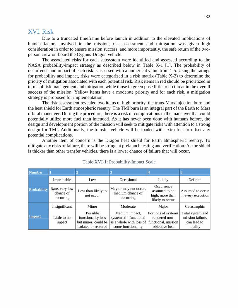
32
XVI. Risk Due to a truncated timeframe before launch in addition to the elevated implications of
human factors involved in the mission, risk assessment and mitigation was given high
consideration in order to ensure mission success, and more importantly, the safe return of the two-
person crew on-board the Cygnus-Dragon vehicle.
The associated risks for each subsystem were identified and assessed according to the
NASA probability-impact strategy as described below in Table X-1 [1]. The probability of
occurrence and impact of each risk is assessed with a numerical value from 1-5. Using the ratings
for probability and impact, risks were categorized in a risk matrix (Table X-2) to determine the
priority of mitigation associated with each potential risk. Risk items in red should be prioritized in
terms of risk management and mitigation while those in green pose little to no threat in the overall
success of the mission. Yellow items have a moderate priority and for each risk, a mitigation
strategy is proposed for implementation.
The risk assessment revealed two items of high priority: the trans-Mars injection burn and
the heat shield for Earth atmospheric reentry. The TMI burn is an integral part of the Earth to Mars
orbital maneuver. During the procedure, there is a risk of complications in the maneuver that could
potentially utilize more fuel than intended. As it has never been done with humans before, the
design and development portion of the mission will seek to mitigate risks with attention to a strong
design for TMI. Additionally, the transfer vehicle will be loaded with extra fuel to offset any
potential complications.
Another item of concern is the Dragon heat shield for Earth atmospheric reentry. To
mitigate any risks of failure, there will be stringent prelaunch testing and verification. As the shield
is thicker than other transfer vehicles, there is a lower chance of failure that will occur.
Table XVI-1: Probability-Impact Scale
Number 1 2 3 4 5
Probability
Improbable Low Occasional Likely Definite
Rare, very low
chance of
occurring
Less than likely to
not occur
May or may not occur,
medium chance of
occurring
Occurrence
assumed to be
high, more than
likely to occur
Assumed to occur
in every execution
Impact
Insignificant Minor Moderate Major Catastrophic
Little to no
impact
Possible
functionality loss
but minor, could be
isolated or restored
Medium impact,
system still functional
as a whole with loss of
some functionality
Portions of systems
rendered non-
functional, mission
objective lost
Total system and
mission failure,
can lead to
fatality
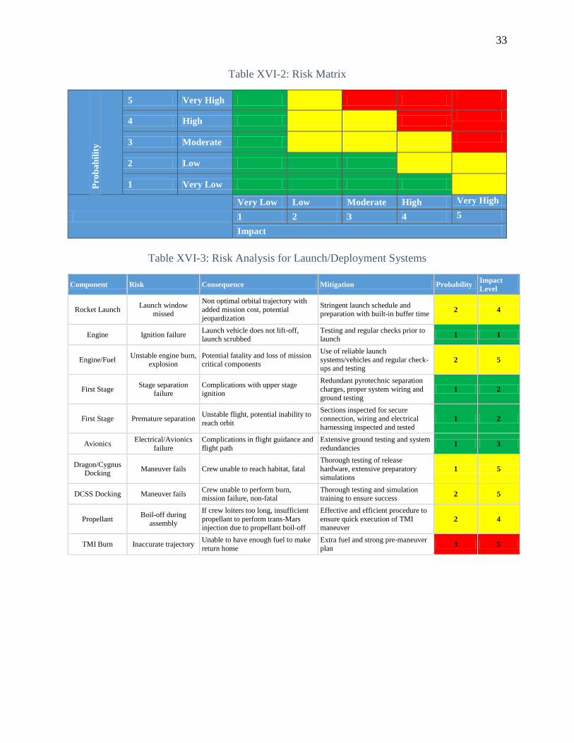
33
Table XVI-2: Risk Matrix
Pro
ba
bil
ity
5 Very High
4 High
3 Moderate
2 Low
1 Very Low
Very Low Low Moderate High Very High
1 2 3 4 5
Impact
Table XVI-3: Risk Analysis for Launch/Deployment Systems
Component Risk Consequence Mitigation Probability Impact
Level
Rocket Launch Launch window
missed
Non optimal orbital trajectory with
added mission cost, potential
jeopardization
Stringent launch schedule and preparation with built-in buffer time
2 4
Engine Ignition failure Launch vehicle does not lift-off, launch scrubbed
Testing and regular checks prior to launch
1 1
Engine/Fuel Unstable engine burn,
explosion Potential fatality and loss of mission critical components
Use of reliable launch
systems/vehicles and regular check-ups and testing
2 5
First Stage Stage separation
failure Complications with upper stage ignition
Redundant pyrotechnic separation
charges, proper system wiring and
ground testing 1 2
First Stage Premature separation Unstable flight, potential inability to
reach orbit
Sections inspected for secure connection, wiring and electrical
harnessing inspected and tested 1 2
Avionics Electrical/Avionics
failure
Complications in flight guidance and
flight path
Extensive ground testing and system
redundancies 1 3
Dragon/Cygnus Docking
Maneuver fails Crew unable to reach habitat, fatal
Thorough testing of release
hardware, extensive preparatory
simulations 1 5
DCSS Docking Maneuver fails Crew unable to perform burn, mission failure, non-fatal
Thorough testing and simulation training to ensure success
2 5
Propellant Boil-off during
assembly
If crew loiters too long, insufficient
propellant to perform trans-Mars
injection due to propellant boil-off
Effective and efficient procedure to
ensure quick execution of TMI
maneuver 2 4
TMI Burn Inaccurate trajectory Unable to have enough fuel to make
return home
Extra fuel and strong pre-maneuver
plan 3 5

34
Table XVI-4: Risk Analysis for Power/Thermal Systems
Component Risk Consequence Mitigation Probability Impact
Level
Solar Arrays Deployment malfunction
Unable to power spacecraft for duration of mission
Rigorous testing before launch, robust design concepts
2 5
Solar Arrays Power collection
failure
Unable to power spacecraft for duration of mission or reduced power
collection
Secondary battery system to store
backup energy, spacecraft ability to
defer to emergency power saving mode
2 4
Solar Arrays Damage from high-
velocity debris
Unable to power spacecraft for
duration of mission or reduced power
collection
Secondary battery system to store
backup energy, spacecraft ability to defer to emergency power saving
mode
1 4
Batteries Battery failure Unable to store excess power
collected from solar array
Usage of reliable Li-Po batteries as
well as primary solar array system 1 2
Batteries Battery
overheating/explosion
Loss of batteries and potential
damage to housing compartments
Usage of reliable Li-Po batteries and
preflight testing procedures 1 1
Electrical Wiring Disconnection,
shorting, damaging
Loss of various on-board systems,
potentially fatal
Circuit redundancies and ground
testing 2 4
Fluid Loops Leakage Loss of fluid pressure and potential damage to sensitive spacecraft
components
Preflight testing and robust design, tools available on-board for en route
repairs 4 2
Fluid Pump Malfunction
Unable to run ATCS, must be
repaired quickly to ensure proper heat rejection
Redundant pump systems and tools
available on-board for en route repairs
3 3
Table XVI-5: Risk Analysis for ECLSS/Human Factors Systems
Component Risk Consequence Mitigation Probability Impact
Level
Water Recover
Loop Leakage
Loss of fluid pressure and complications in water recycling and
recirculation
Preflight testing and robust design, tools available on-board for en route
repairs
2 3
Air Revitalization
Element Failure
Inability to regulate CO, CO2, and
relative humidity levels and provide clean oxygen to crew
Multiple design redundancies and
training to fix any issues on-board 2 5
Waste Processing
System Failure Inability to manage solid waste
Multiple design redundancies and
training to fix any issues on-board 2 1
Airlock System Failure/Leakage Potentially deadly if unable to ensure airtight seal for crew
Stringent testing and design before flying mission
1 5
Radiation
Exposure
Excessive radiation
dosage Assorted adverse health effects
Well-designed radiation shielding in
crew habitat, with water,
Polyethylene, and metals, and dosimeter detectors
1 3
Physical Health Illness
Impaired functioning of human crew,
potential spread and contamination throughout capsule
Vaccinations, pre-mission health
exams, included medical equipment
and relevant training, and robust air & water filtration to eliminate
pathogens
2 1
Mental/Emotional
Health
Depression/Morale
Issues Performance of crew hampered
Rigorous crew selection criteria, routine fitness and health regimens,
human interaction 3 1

35
Table XVI-6: Risk Analysis for Avionics, Controls, and Navigation Systems
Component Risk Consequence Mitigation Probability Impact
Level
Startrackers/Sun
Sensor Malfunction
Unable to determine spacecraft
attitude
Redundancies of devices on spacecraft (IMU and dual SS
Trackers)
2 4
On-board
Computer Malfunction
Unable to compute navigation
commands for spacecraft guidance Redundancies in computer systems 1 5
Antennae Failure Unable to carry communications
between spacecraft & Earth
Redundancies through multiple
antennae on spacecraft 1 3
Aerojet Thrusters Failure Unable to fire for course and attitude
corrections
Rigorous on ground testing and
usage of space proven thrusters in different areas on vehicle
2 4
Transponder Malfunction Cannot transform radio frequencies
to send out
Redundancy transponder with
prelaunch testing 1 2
Hydrazine
Propellant Leakage/Boil Off
Loss of total impulse able to be
imparted on vehicle
Preflight checks for securing the
propellant 2 3
Table XVI-7: Risk Analysis for Spacecraft Structure
Component Risk Consequence Mitigation Probability Impact
Level
Cygnus Habitat Damage from high-
velocity debris Hull damage, potential breach Installation of MMODs 2 3
MLI Damage from high-
velocity debris
Thermal leaking around damaged
area Installation of MMODs 2 2
Heat Shield Performance failure Unable to re-enter Earth atmosphere,
fatal
Prelaunch inspection, prior success with Dragon capsule with thicker
heat shield
3 5
Propellant Tanks Leakage/Failure Loss of valuable propellant
Prelaunch inspection, ensuring seals
and structural integrity of
component
3 4
Momentum Disks Mechanical failure Unable to accurately actuate
spacecraft attitude
Redundant sets of 3-axis momentum
disks 1 1

36
XVII. References
[1] J. Chilton, "A New Framework for Human Space Exploration," October 18, 2012. [Online].
Available: https://info.aiaa.org/Regions/SE/HSV_AIAA/Downloadable%20Items/AIAA-
Chilton_18Oct2012_Final2.pdf.
[2] S. J. H. a. D. J. Creech, "SLS Dual Use Upper Stage (DUUS) Opportunities," 2013. [Online].
Available: http://ntrs.nasa.gov/archive/nasa/casi.ntrs.nasa.gov/20130013953.pdf.
[3] "Falcon Heavy," Space Exploration Technologies, 2014. [Online]. Available:
http://www.spacex.com/falcon-heavy.
[4] United Launch Alliance, "Delta IV Launch Services User’s Guide," June 2013. [Online].
[5] D. A. e. a. Tito, "Feasibility Analysis for a Manned Mars Free-Return Mission in 2018," IEEE,
2013.
[6] Jet Propulsion Laboratory, "Mars Reconnaissance Orbiter: Trajectory Correction Maneuvers,"
[Online]. Available: http://mars.jpl.nasa.gov/mro/mission/timeline/mtapproach/approachtcms/.
[7] Boeing, "Delta 269 (Delta III) Investigation Report," 16 August 2000. [Online].
[8] A. H. T. B. L. Hastings, "Analytical Modeling and Test Correlation of Variable Density Multilayer
Insulation for Cryogenic Storage," Marshal Spaceflight Center, [Online]. Available:
http://ntrs.nasa.gov/archive/nasa/casi.ntrs.nasa.gov/20040121015.pdf.
[9] F. Z. S. L. B. Kutter, "Atlas Centaur Extensibility to Long-Duration In-Space Applications,"
Lockheed Martin Space Systems Company, 2005. [Online]. Available:
http://www.ulalaunch.com/site/docs/publications/AtlasCentaurExtensibilitytoLongDurationInSpac
eApplications20056738.pdf.
[10] B. K. J. Kruid, "Centaur Upperstage Applicability for Several-Day Mission Durations with Minor
Insulation Modifications," United Launch Alliance, 2007. [Online].
[11] Lyndon B. Johnson Space Center, "Man-Systems Integration Standards: Architecture," July 1995.
[Online]. Available: http://msis.jsc.nasa.gov/sections/section08.htm.
[12] Boeing Defense, Space & Security, "Destiny Laboratory Module," [Online]. Available:
http://www.boeing.com/boeing/defense-space/space/spacestation/components/us_laboratory.page.
[13] Bigelow Aerospace, "Genesis 1 Specifications," [Online]. Available:
http://www.bigelowaerospace.com/genesis-1-specs.php.
[14] Bigelow Aerospace, "Sunancer," [Online]. Available:
http://www.bigelowaerospace.com/sundancer.php.
[15] Bigelow Aerospace, "BA-330," [Online]. Available:
http://www.bigelowaerospace.com/ba330.php.

37
[16] Orbital Sciences Corporation, "Cygnus Spacecraft: Cygnus Overview," [Online]. Available:
http://www.orbital.com/NewsInfo/MissionUpdates/Orb-1/files/Cygnus%20_overview.pdf.
[17] National Aeronautics and Space Administration, "International Space Station: Facts and Figures,"
November 2010. [Online]. Available:
http://www.nasa.gov/mission_pages/station/main/onthestation/facts_and_figures.html#.UyQAnvk
7tcY.
[18] Orbital Sciences Corporation, "Cygnus Advanced Maneuvering Spacecraft," [Online]. Available:
http://www.orbital.com/AdvancedSystems/Publications/Cygnus_factsheet.pdf.
[19] National Aeronautics and Space Administration, "Stardust Sample Return: Press Kit," January
2006. [Online].
[20] Inspiration Mars Foundation, "Inspiration Mars Architecture Study Report Summary," [Online].
Available:
http://www.inspirationmars.org/IM%20Architecture%20Study%20Report%20Summary.pdf.
[21] "Heat Shield for NASA's Orion Spacecraft Arrives at Kennedy Space Center," 5 December 2013.
[Online]. Available: http://www.nasa.gov/content/heat-shield-for-nasas-orion-spacecraft-arrives-
at-kennedy-space-center/#.UyOroPk7tcY.
[22] Lyndon B. Johnson Space Center, "Orion Quick Facts," 2011. [Online]. Available:
http://www.lpi.usra.edu/lunar/constellation/orion/factsheet2.pdf.
[23] "NASA Exploration Roadmap: A return to the Moon’s surface documented," 19 March 2012.
[Online]. Available: http://www.nasaspaceflight.com/2012/03/nasa-exploration-roadmap-return-
moons-surface-documented/.
[24] D. Tito, "Dennis Tito Written Statement Commerical Space Hearing," 20 November 2013.
[Online]. Available: http://www.inspirationmars.org/Written_Testimony_DTito_Nov2013.pdf.
[25] "Low Density Ablator Composition," 23 July 2001. [Online]. Available:
http://www.google.com/patents/US6627697.
[26] Space Exploration Technologies, "Dragon," [Online]. Available: http://www.spacex.com/dragon.
[Accessed 2014].
[27] Space Exploration Technologies, "PICA Heat Shield," 4 April 2013. [Online]. Available:
http://www.spacex.com/news/2013/04/04/pica-heat-shield.
[28] Alliant Techsystems Inc., "ATK Space Propulsion Products Catalog," September 2012. [Online].
Available: http://www.atk.com/wp-content/uploads/2013/02/ATK-Motor-Catalog-2012.pdf.
[29] Space Exploration Technologies, "SpaceX CRS-1 Mission Press Kit," National Aeronautics amd
Space Administration, [Online]. Available: http://www.nasa.gov/pdf/694166main_SpaceXCRS-
1PressKit.pdf.
38
[30] Federal Aviation Administration, "The Annual Compendium of Commercial Space Transportation:
2012," February 2013. [Online].
[31] "NASA Glenn Contributions to the International Space Station (ISS) Electrical Power System," 20
September 2011. [Online]. Available: http://www.nasa.gov/centers/glenn/about/fs06grc.html.
[32] T. R. David Smitherman, "Deep Space Habitat Configurations Based on International Space
Station Systems," Marshall Space Flight Center, 2012. [Online]. Available:
http://ntrs.nasa.gov/archive/nasa/casi.ntrs.nasa.gov/20120014600.pdf.
[33] S. W. B. D. A. ,. S. S. H. J. F. S. R. O. G. A. L. Michael F. Piszczor, "Advanced Solar Cell and
Array Technology for NASA Deep Space Missions," John Glenn Research Center, [Online].
Available: http://ntrs.nasa.gov/archive/nasa/casi.ntrs.nasa.gov/20090007813.pdf.
[34] "Space Communications with Mars," [Online]. Available: http://www.astrosurf.com/luxorion/qsl-
mars-communication3.htm.
[35] D. K. L. S. S. Jim Taylor, "Mars Reconnaissance Orbiter Telecommunications," Jet Propulsion
Laboratory, September 2006. [Online].
[36] L. Herrera, "Space Shuttle Star Tracker Challenges," 13 May 2010. [Online]. Available:
ntrs.nasa.gov/search.jsp?R=20110003998.
[37] Aerojet Rocketdyne, "Monopropellant Rocket Engines," 13 March 2014. [Online].
[38] National Aeronautics and Space Administration, "NASA Office of Planetary Protection," [Online].
Available: http://planetaryprotection.nasa.gov/solar. [Accessed 13 March 2014].
[39] J. C. K. Dina El Sherif, "International Space Station Carbon Dioxide Removal Assembly Concepts
and Advancements," 2005. [Online]. Available:
http://ntrs.nasa.gov/archive/nasa/casi.ntrs.nasa.gov/20050210002.pdf.
[40] T. T. Qiyong Xu, "ECLSS Final Report," University of Colorado, [Online]. Available:
http://www.colorado.edu/ASEN/project/mob/ECLSS_final_report%2012-13-
03%20version%202.doc.
[41] Kennedy Space Center, "Water Coolant Loop System," 12 January 1994. [Online].
[42] M. A. B. J. F. B. James Lee Broyan Jr, "James Lee Broyan Jr, Melissa Ann Borrego, Juergen F.
Bah," 2008. [Online]. Available: James Lee Broyan Jr, Melissa Ann Borrego, Juergen F. Bah.
[43] S. T. Michelle Rucker, "Developing a habitat for long duration, deep space missions," [Online].
[44] L. A. Palinkas, "Psychosocial Effects of Adjustment in Antartica: Lessons for Long-Duration
Spaceflight," AIAA Journal VOL 27, No. 5, Oct 1990. [Online]. Available:
http://arc.aiaa.org/doi/pdf/10.2514/3.26167.

39
[45] J. Corwin, "The Psychological Dangers of Long-Duration Spaceflight”, Page 7. Life on Mars?:
Final Paper," [Online]. Available:
http://www.dartmouth.edu/~humbio01/s_papers/2002/Corwin.pdf.
[46] Penn Medicine News Release, "520-Day Simulated Mission to Mars Reveals Critical Data about
Sleep and Activity Needs for Astronauts," 7 January 2013. [Online]. Available:
http://www.uphs.upenn.edu/news/News_Releases/2013/01/dinges/.
[47] NASA Science News, "Wide Awake in Outer Space," 2001. [Online]. Available:
http://science.nasa.gov/science-news/science-at-nasa/2001/ast04sep_1/.
[48] BBC News, "NASA to Test Space-Sleep Colour-Changing Lights," 17 December 2012. [Online].
Available: http://www.bbc.com/news/technology-20753888.
[49] T. Quine, "Space adaptation syndrome affects about half of astronauts as the body adapts to
microgravity," April 2007. [Online].
[50] J. J. B. R. J. M. R. Dana Carpenter, "Effects of Long-Duration Spaceflight, Microgravity and
Radiation on Neuromuscular, Sensorimotor, and Skeletal Systems," 2010. [Online]. Available:
http://journalofcosmology.com/Mars147.html.
[51] NASA ISS Science for Everyone, "Advanced Resistive Exercise Device (ARED)," 9 January
2013. [Online]. Available: Advanced Resistive Exercise Device (ARED).
[52] D. B. D. C. F. C. X. J. I. M. M. P. V. P. G. R. a. T. S. G. Dietze, "Assessment of Radiation
Exposure of Astronauts in Space.," [Online].
[53] S. Koontz, "Estimating the effects of astronaut career ionizing radiation dose limits on manned
interplanetary flight programs," 18 July 2013. [Online].
[54] Johnson Space Center, "Spaceflight Radiation Health Program," [Online]. Available: http://srag-
nt.jsc.nasa.gov/Publications/TM104782/techmemo.htm. [Accessed 14 March 2014].
[55] S. A. S. A. M. A. W. I. A. D. P. M. M. Gandolph J, "Food for a mission to Mars: Investigations of
low-dose gamma radiation effects," Institute of Food Technologists and the International Union of
Food Science and Tech, 2007. [Online].
[56] K. G. a. J. Rhone, "Cytogenetic biodosimetry using the blood lymphocytes of astronauts," 2012.
[Online].
[57] La Rivista del Nuovo Cimento, "Biological dosimetry in astronauts," 1996. [Online].
[58] E. Howell, "'Astroskin,' an Astronaut Smart Shirt, Gets Icy Test in Antarctica," Space.com, 28
February 2014. [Online]. Available: http://www.space.com/24850-astronaut-astroskin-antarctic-
expedition.html.
[59] B. Gholipour, "Stethoscopes Could Soon Be Replaced By Hand-Held Ultrasound Devices, Doctors
Say," Huffington Post, 24 January 2014. [Online]. Available:

40
http://www.huffingtonpost.com/2014/01/24/stethoscope-replaced-ultrasound-
devices_n_4658869.html.
[60] National Aeronautics and Space Administration, "Factors Impacting Habitable Volume
Requirements: Results from the 2011 Habitable Volume Workshop," 21 April 2011. [Online].
[61] S. Money, "Competition and EELV: Challenges and Opportunities and New Launch Vehicle
Acquisition," 2012. [Online]. Available: http://spirit.as.utexas.edu/~fiso/telecon/Money_5-9-
12/Money_5-9-12.pptx. [Accessed 11 March 2014].
[62] George C. Marshall Space Flight Center, "NASA Fact Sheet: NASA Space Launch System," 2011.
[Online]. Available: http://www.nasa.gov/pdf/664158main_sls_fs_master.pdf.
[63] Space Exploration Technologies, "Falcon 9," [Online]. Available: http://www.spacex.com/falcon9.
[Accessed 9 March 2014].
XVIII. Appendix A: Mass Budget Subsystem Mass
Command and Data Handling 45
Attitude Determination and Control Hardware 120
RCS Propellant 210
Communication 105
Food 1250
Water 1225
Water Recycling + Spares 675
Air 485
Air Recycling + Spares 850
Thermal + Spares 1220
Crew Accommodations/Interior Structures 265
Crew Personal Effects 30
Dragon Capsule 6000
Cygnus Super Enhanced PCM and Service Module Bus 2300
Solar Arrays 325
Batteries 120
Integration of Dragon with Cygnus 150
Payload Attachment Fitting 350
Crew Person Mass 150
Total 15875

ID Task Name Duration Start Finish
1 Program Definition 32 days 5/15/2014 6/14/2014
2 Core Mission Design 120 days 6/26/2014 10/19/2014
3 Development 240 days 9/14/2014 5/3/2015
4 Testing 450 days 2/18/2015 4/27/2016
5 Construction/Manufacturing 650 days 4/13/2015 12/30/2016
6 Integration/Assembly 440 days 4/11/2016 6/9/2017
7 Launch Preparation & Check 150 days 8/2/2017 12/24/2017
8 Launch Window 10 days 12/24/2017 1/2/2018
9 In-Orbit Vehicle Assembly (Predicted) 0 days 1/1/2018 1/1/2018
10 Trans-Mars Injection Burn (Predicted) 0 days 1/1/2018 1/1/2018
11 Earth To Mars Transit 227 days 1/1/2018 8/8/2018
12 Mars Flyby 1 day 11/13/2018 11/13/2018
13 Mars To Earth Transit 274 days 11/13/2018 8/4/2019
14 Dragon Earth Reentry 1 day 11/29/2019 11/29/2019
15 Splashdown 0 days 11/29/2019 11/29/2019
16 Capsule & Crew Recovery 0 days 11/29/2019 11/29/2019
1/1
1/1
11/29
11/29
Q4 Q1 Q2 Q3 Q4 Q1 Q2 Q3 Q4 Q1 Q2 Q3 Q4 Q1 Q2 Q3 Q4 Q1 Q2 Q3 Q4 Q1 Q2 Q3 Q4 Q1 Q2 Q3 Q4
2013 2014 2015 2016 2017 2018 2019 2020
Task
Split
Milestone
Summary
Project Summary
Inactive Task
Inactive Milestone
Inactive Summary
Manual Task
Duration-only
Manual Summary Rollup
Manual Summary
Start-only
Finish-only
External Tasks
External Milestone
Deadline
Progress
Manual Progress
Page 1
Project: IMGantChart.mpp
Date: 3/15/2014