ilmix w:ir sm9pey asimjp firec - world bank · world bank technical paper number 19 w tp-19 ilmix...
TRANSCRIPT

WORLD BANK TECHNICAL PAPER NUMBER 19 W TP-19
ILMiX W:ir SM9pEy aSimjp FirecLaboratory Testing of Handpumps for Developing Countries:Final Technical Report
Consumers' Association Testing and Research Laboratories
TJ1903.133 1984 c.2 -frdvlpnconie LaboratorY testing of handpumPs
SLCO524 O' ~~port Number 3F A joint United Nations Development Program and World Bank Contribution
j to the International Drinking Water Supply and Sanitation Decade1981-1990
Pub
lic D
iscl
osur
e A
utho
rized
Pub
lic D
iscl
osur
e A
utho
rized
Pub
lic D
iscl
osur
e A
utho
rized
Pub
lic D
iscl
osur
e A
utho
rized

WORLD BANK TECHNICAL PAPERS
No. 1. Increasing Agricultural Productivity
No. 2. A Model for the Development of a Self-help Water Supply Program
No. 3. Ventilated Improved Pit Latrines: Recent Developments in Zimbabwe
No. 4. The African Typanosomiases: Methods and Concepts of Control
and Eradication in Relation to Development
(No. 5.) Structural Changes in World Industry: A Quantitative Analysis
of Recent Developments
No. 6. Laboratory Evaluation of Hand-operated Water Pumps for Use
in Developing Countries
No. 7. Notes on the Design and Operation of Waste Stabilization Ponds
in Warm Climates of Developing Countries
No. 8. Institution Building for Traffic Management
(No. 9.) Meeting the Needs of the Poor for Water Supply and Waste Disposal
No. 10. Appraising Poultry Enterprises for Profitability: A Manual
for Investors
No. 11. Opportunities for Biological Control of Agricultural Pests
in Developing Countries
No. 12. Water Supply and Sanitation Project Preparation Handbook: Guidelines
No. 13. Water Supply and Sanitation Project Preparation Handbook: Case Studies
No. 14. Water Supply and Sanitation Project Preparation Handbook: Case Study
(No. 15.)Sheep and Goats in Developing Countries: Their Present and
Potential Role
(No. 16.)Managing Elephant Depredation in Agricultural and Forestry Projects
(No. 17.)Energy Efficiency and Fuel Substitution in the Cement Industry
with Emphasis on Developing Countries
No. 18. Urban Sanitation Planning Manual Based on the Jakarta Case Study
( ) Indicates numbers assigned after publication
Rural Water Supply Handpumps Project
UNDP Project Management Report Number 3
SECTORAL LIBPARYINTERNAInONAL BANK
FOR EEOMN
RECONSTRULCTION AND DEVELOPMENT
IAN 1 8 1985

RURAL WATER SUPPLY HANDPUMPS PROJECT
INT/81/026
The UNDP/World Bank project for laboratory and field testing
and the technological development of handpumps for community water supply
is aimed at promoting the use of suitable handpumps for groundwater
extraction to meet the goals of the International Drinking Water Supply
and Sanitation Decade. In the selection of pumps and in some cases their
further development, consideration is given to their durability, capital
as well as maintenance costs, suitability for village-level maintenance,
and prospects for local manufacture.
Reports on handpumps testing and development are published
periodically, at least once a year, for the duration of the project. The
following reports have been published or are in preparation:
Report No. 1. Laboratory Tests on Hand-Operated WaterPumps for Use in Developing Countries:Interim Report. 1982.
Report No. 2. Laboratory Evaluation of Hand-OperatedWater Pumps for Use in Developing Countries.1983.
Report No. 3. Laboratory Testing of Handpumps forDeveloping Countries: Final TechnicalReport. 1984.
Report No. 4. Handpump Testing and Development: InterimReport (in preparation). 1984.

WORLD BANK TECHNICAL PAPER NUMBER 19
Laboratory Testing of Handpumps for Developing Countries
Final Technical Report
Consumers' Association Testing and Research Laboratories
The World BankWashington, D.C., U.S.A.

Copyright 0 1984The International Bank for Reconstructionand Development / THE WORLD BANK1818 H Street, N.W.Washington, D.C. 20433, U.S.A.
First printing June 1984All rights reservedManufactured in the United States of America
This is a document published informally by the World Bank. In order that
the information contained in it can be presented with the least possible
delay, the typescript has not been prepared in accordance with the
procedures appropriate to formal printed texts, and the World Bank accepts
no responsibility for errors. The publication is supplied at a token charge to
defray part of the cost of manufacture and distribution.
The views and interpretations in this document are those of the author(s)
and should not be attributed to the World Bank, to its affiliated
organizations, or to any individual acting on their behalf. Any maps used
have been prepared solely for the convenience of the readers; the
denominations used and the boundaries shown do not imply, on the part of
the World Bank and its affiliates, any judgment on the legal status of any
territory or any endorsement or acceptance of such boundaries.
The full range of World Bank publications, both free and for sale, is
described in the Catalog of Publications; the continuing research program is
outlined in Abstracts of Current Studies Both booklets are updated annually;
the most recent edition of each is available without charge from the
Publications Sales Unit, Department T, The World Bank, 1818 H Street, N.W.,
Washington, D.C. 20433, U.S.A., or from the European Office of the Bank, 66,
avenue d'1ena, 75116 Paris, France.
Library of Congress Cataloging in Publication Data
Main entry under title:
Laboratory testing of handpumps for developing countries.
(A World Bank technical paper, ISSN 0253-7494 ; no. 19)
1. Hand pumps--Testing. 2. Hand pumps--Developingcountries. I. Consumers' Association Testing and Research
Laboratories. II. Series.TJ903.L33 1984 628'.72 83-26059
ISBN 0-8213-0311-2

-v -
ABSTRACT
This is the full technical report on laboratory tests on the thirdbatch of 6 handpumps, carried out at the Consumers' Association Testing andResearch Laboratory at Gosfield, U.K. It also includes similar informationon the 12 pumps tested for the World Bank in Batches 1 and 2. (A summary ofthe test results for Batches 1 and 2 was published by the World Bank as UNDPProject Management Report No. 2 in March 1983.)
The test program was extensive, and all aspects of the evaluationare described in detail. Some general observations are noted, and for eachpump there are sections on general information, inspection, weights andmeasures, engineering assessment, pump performance, user trial, endurance,abuse tests, and verdict, as well as examples of the force/displacementdiagrams taken during the evaluation.
The information in this report is intended to
(i) Assist handpump manufacturers in improving thequality of their products
(ii) Assist authorities and agencies in developingcountries in deciding between local manufacturingor importation of handpumps
(iii) Provide agencies in developing countries with anevaluation of handpumps in order to enable a moreinformed choice of pump to be made, and to ensurethe right pump is selected to suit particulardeveloping country conditions.

- vi -
ABSTRAIT
Le document ci-apres est le rapport technique complet duConsumers' Association Testing and Research Laboratory (Laboratoired'essais et de recherches de l'Association des consommateurs, Gosfield,Royaume-Uni) sur 1'essai de la troisieme serie de six pompes a motricitehumaine. I1 comprend egalement des renseignements similaires sur les12 pompes des series 1 et 2 test6es pour la Banque mondiale. (Un resumedes resultats de ces essais avait ete publie en mars 1983 par la Banquemondiale sous le titre "Rapport de la direction du Projet No 2 - PNUD".)
Le programme d'evaluation comprenait de nombreux tests dont tousles aspects sont d6crits en detail. Le rapport debute par des observa-tions generales et presente ensuite une evaluation detaill6e de chaquepompe (renseignements g6neraux, inspection, poids et dimensions, 6valua-tion technique, performances, tests des utilisateurs, tests d'endurance,tests de degradation et verdict), ainsi que des exemples des courbeseffort/hauteur etablies au cours de 1'6valuation.
Les informations du pr6sent rapport visent
i) a aider les fabricants de pompes a motricite humaine aam6liorer la qualite de leurs produits;
ii) a aider les autorites et organismes des pays en d6velop-pement a decider s'il vaut mieux fabriquer ces pompes surplace ou les importer;
iii) a fournir aux organismes des pays en developpement uneevaluation des pompes A motricite humaine qui leur permettede choisir en connaissance de cause un appareil adapte auxconditions particulieres de leur pays.

- vii -
ABSTRACTO
Este es el informe t6cnico completo sobre los ensayos de labora-torio del tercer lote de seis bombas de agua de mano, que se Ilevaron acabo en el laboratorio de ensayos e investigaci6n de la asociaci6n de con-sumidores (Consumers' Association Testing and Research Laboratory) enGosfield, Reino Unido. Comprende informaci6n semejante sobre las 12 bom-bas que ensay6 el Banco Mundial en los lotes 1 y 2. (El Banco Mundialpublic6 un resumen de los resultados del ensayo de los lotes 1 y 2, con eltitulo de PNUD-INT/81/206, Informe No. 2 sobre la marcha del proyecto, enmarzo de 1983.)
El programa de ensayos fue extenso y se describen detalladamentetodos los aspectos de la evaluaci6n. Se formulan algunas observacionesgenerales y para cada bomba se presenta una secci6n sobre informaci6ngeneral, inspecci6n, peso y medidas, evaluaci6n tecnica, funcionamiento,ensayo con usuarios, resistencia, ensayo de maltrato y --finalmente--veredicto, asi como ejemplos de diagramas de fuerza/desplazamiento traza-dos por computadora durante la evaluaci6n.
La informaci6n de este informe tiene por objeto:
i) Ayudar a los fabricantes de bombas de agua de mano a mejo-rar la calidad de sus productos.
ii) Ayudar a las autoridades e instituciones de los paises endesarrollo a decidir entre fabricar bombas de mano en elpais e importarlas.
iii) Suministrar a las instituciones de los paises en desarrollouna evaluaci6n de las bombas de agua de mano a fin de quepuedan escoger con mayor conocimiento de causa el tipo debomba que han de fabricar, y asegurar que cada pais endesarrollo escoja la bomba que mejor se adapte a suscondiciones.


- ix -
CONTENTS
ABSTRACT ...................................................... v
ACKNOWLEDGEMENTS ........................... x
PREFACE ......................................................... xi
1. INTRODUCTION TO LABORATORY TESTING ...... .................... 1
2. TEST PROCEDURES FOR HANDPUMP EVALUATION ..... ................ 4
Summary . ............................................... 4Detailed Description ........ ........................... 6Installation for Testing ....... ........................ 13Basic Pump Nomenclature ....... ......................... 15
3. GENERAL OBSERVATIONS AND RECOMMENDATIONS ..... ............... 16
Observations .... ................................ 16Recommendations from the 18 Pumps Tested .... ........... 19
4. INDIVIDUAL PUMP EVALUATION ................................ 20
Abi-Vergnet ASM ..................... 22Petro ..................... 34Funymaq ..................... 44Maldev (head only) ..................... 54Rower ..................... 62Volanta ..................... 72Korat 608 A-1 ..................... 92Kawamoto Dragon No. 2 ..................... 102Moyno IV 2.6 ..................... 112Briau Nepta ..................... 122Atlas Copco Kenya ...................................... 132Bangladesh New No. 6 .................................... 144Nira AF-76 ....................................... 154Ethiopia Type BP50 ..................................... 164Vereinigte Edelstahlwerke (VEW) A 18 ...... ............. 172Jetmatic . ...................................... 182Bandung Shallow-well .................................... 192Sumber Banyu ("SB") .................................... 202
APPENDIX I Statistical Analysis of User Responses .... ........ 212
APPENDIX II Force Displacement Diagrams ..... .................. 216
APPENDIX III Abstract of ODA Handpump Final Report,January 1981 ....... ............................ 266

ACKNOWLEDGEMENTS
This project, financed by UNDP projects GLO/79/010 and INT/81/026,
has benefited from the comments received from many sources following
publication in 1980 of the report "Hand and Foot-operated Water Pumps for Use
in Developing Countries" by J.A. Kingham. This was the result of two and a
half years work funded by the Overseas Development Administration of the
United Kingdom Government and laid the foundations of the test protocol for
this current project.
C A Testing and Research staff contributing to this project
included Frank Jones, John Kingham, Timothy Lister and Clive Wade - testing
division; Robert Brown, Michael Clarke, James Horn, Geoffrey Hughes,
John Keen and Malcolm Osborne - engineering division; Cate Andrews,
Margery Feeney, Dorothy Pattie and Edda Wyatt - administrative division.
Tony Reynolds did the pump illustrations.
John M. ReynoldsDon J. UnwinKen J. Mills
Censumers' AssociationTesting and Research Laboratories
Harpenden RiseHarpendenHertfordshire AL5 3BJEngland

- xi -
PREFACE
Among the 1500 million people in developing countries who do nothave access to adequate water supply and sanitation facilities, there are1200 million who lack these basic services in rural areas.
The importance of providing safe water has been repeatedly stressedby national governments and international agencies. Recognizing the urgentneed for improved water and waste management, the United Nations has declaredthe 1980's to be the International Drinking Water Supply and Sanitation Decade(IWSSD), establishing an ambitious goal to provide adequate water to the totalrural population of the developing countries.
Handpumps installed in wells where groundwater is easily availableprovide one of the simplest and least costly methods of supplying the ruralpopulation with water. However, despite all efforts in the past, a numberof serious problems remain to be solved.
Among the activities of the Decade is the project on "LaboratoryTesting, Field Trials and Technological Development of Handpumps", funded bythe United Nations Development Programme (UNDP) Division for Global andInterregional Projects. The World Bank, with responsibility assigned to theWater Supply and Urban Development Department, was selected to be theexecuting agency to undertake the handpumps project.
In the preparatory phase of the project, laboratory testing of anumber of handpumps has started, contracted to the Consumers' AssociationTesting and Research (CATR) Laboratories, of Harpenden, U.K. Two interimreports on the laboratory test results for the first twelve pumps testedunder the Project were issued in March 1982 and March 1983. The present
report contains the full technical results of the laboratory tests on thethird batch of six pumps as well as the twelve pumps from the previoustests.
Future reports from the Project will deal with laboratory testson additional pumps, field trial results, and other related subjects.Handpump laboratory tests which are currently in progress at CATR are mostlyfunded by the manufacturers themselves, since the focus of the HandpumpsProject has shifted to field trials in developing countries. The resultsobtained so far from the field will be described in an interim report, soonto be published as Report No. 4.
The aim of the laboratory tests is to examine and assist in theselection of a wide range of handpumps for further field trials and toprovide information to all interested manufacturers to assist them in theproduction of more efficient and more reliable pumps.
The long-range\objective of the project is to promote the improveddesigns of handpumps locally manufactured in developing countries, pumpsthat can be maintained by trained village operators (VLOM pumps - VillageLevel Operated and Maintained). The project is also concerned with thesocial, organizational, and economic factors which are essential if ahandpump programme is to be successful. Although technical evaluation anddevelopment are urgent considerations, they alone will not be sufficient toresolve the problems confronted by handpump programmes.

- xii -
In time, reports on field trials in developing countries and
technological development of handpumps will be produced which will show how
improvements in design and manufacturing quality of handpumps are materially
helping towards reaching the goals of the IWSSD.
Among the major outputs of the project will be a financial
analysis based on projected annual costs for maintenance and operation of a
variety of handpumps. For this purpose we would be grateful to receive any
information on maintenance costs, particularly as related to the frequency
of breakdowns and the type of maintenance system employed, obtained from
field operations or tests organized by a developing country government, aid
agency, non-governmental organization, or others.
Comments on this report are most welcome.
Saul Arlosoroff, ChiefApplied Research & Technology, WUD
(UNDP Projects Manager, INT/81/026, GLO/80O004, INT/82/002)The World Bank
1818 H Street, N.W.Washington, D.C. 20015 USATelex: RCA 248423 WORLDBKTelephone: (202) 676-1790

- 1 -
1. INTRODUCTION TO LABORATORY TESTING
After a series of meetings during which experts recognized theimportance of handpumps for community use in the economy of developingcountries, the Overseas Development Administration of the U.K. Governmentdecided in 1977 to test 12 different deep-well pump designs in theConsumers' Association Testing and Research Laboratory in an attempt toidentify the reasons for early field failures and to obtain better value forthe money spent in Overseas aid. The ODA required all the laboratoryinformation, including details of a long endurance test, to be submitted tothe manufacturers to assist them in improving the quality and reliability oftheir products. The pumps tested were the Petropump 95, Vergnet, Dempster,Mono, Climax, Godwin, Abi, GSW (Beatty), Monarch, Kangaroo, India Mk II andConsallen. Their performance is briefly summarized in Appendix III. Asummary of the ODA report can be obtained from the Manager, UNDP HandpumpsProject, WUD, The World Bank.
UNDP and The World Bank recognized that the aims of theInternational Decade of Drinking Water Supply and Sanitation would begreatly assisted if this work was continued and, more importantly, coupledwith extensive field trials and technological development in developingcountries.
Testing of three batches, numbering six pumps each, has now beencompleted, and is the subject of this technical report. A further batch ofpumps containing the Mono lift ES30 (UK), the Mono rotary direct drive(South Africa), the Kardia lever arm pump, two versions of the Turni rotarypump from Preussag (Germany) and the Sihilase pump (Sri Lanka) have almostreached completion of the evaluation. Results of these tests will bepublished in due course.

- 2 -
Table 1: BRAND LIST of PUMPS TESTED in BATCH 3
Deep or Price Country
Shallow (US$)* of
Name/Model Manufacturer/Supplier Well Approx Origin
Abi-Vergnet Groupement Abidjan Deep 83 6a Ivory Coast
ASM Industrie SNE; (Pumpstand);
Mengin France(Pumpingelement)
Petro WellDrill Systems AB Deep 465 Sweden
Funymaq Georgia Institute Deep Not Honduras
of Technology supplied
Maldev Petroleum Services Not Malawi
(Malawi) Limited supplied
Rower Mirpur Agricultural Shallow 13.50 Bangladesh
Workshop Training
School
Volanta Jansen Venneboer bv Deep 845a Netherlands
* Cost if 50'purchased in one order
# The Maldev is a pumpstand only. A below-ground assembly is under
development for deep wells.
a Supplied complete for 20 m depth.

- 3 -
Table 2: BRAND LIST of PUMPS TESTED in BATCHES 1 and 2
Deep or Price CountryShallow (US$)* of
Name/Model Manufacturer/Supplier Well Approx Origin
Korat Saha Kolkarn Deep 295a Thailand608 A-1
Dragon Kawamoto Deep+ 362b JapanNo. 2 (D)
Moyno Robbins & Myers Deep 55 0c USAIV 2.6 739d
Nepta Briau Deep 650d France
Kenya Atlas Copco Deep (669) Kenya
New No. 6 Engineers Wood Shallow (33) BangladeshSteel Industries Suction
Nira AF76 Vammalan Konepaja oy Deep 20 3e Finland
Ethiopia E.W.W.C.A. Shallow (75) EthiopiaType BP50 force0
VEW A18 Vereinigte Deep 1583a AustriaEdelstahlwerke (VEW)
Jetmatic Sea Commercial Co. Deep 32f Philippines
Bandung C.V. Malabar Shallow (54) IndonesiaSuction
Sumber P.T. Celco Deep (85) IndonesiaBanyu("SB")
+ Was supplied as shallow-well pump with additional components forconversion to deep-well use
o 12 metres nominal maximum depth* Cost if 50 purchased in one order. Figures in () are 1981 prices,
otherwise 1982.
a Supplied complete for 20 m depthb Supplied complete for deep-well usec Pump onlyd With 20 m below-ground assemblye Pump and cylinderf Without connecting rod and rising main

- 4 -
2. TEST PROCEDURES FOR HANDPUMP EVALUATION
2.1 Summary
1. Obtaining Pumps 1.1 Manufacturer or Agency1.2 Pump model and type1.3 Cost1.4 Delivery time
2. Inspection 2.1 Packaging2.2 Condition of Pumps2.3 Literature
3. Weights and 3.1 Weights of principal components
Measures 3.2 Principal dimensions3.3 Cylinder bores3.4 Ergonomic measurements
4. Engineering 4.1 Materials, manufacturing methods, fitness for
Assessment purpose4.2 Suitability for manufacture in developing countries
4.3 Ease of installation, maintenance and repair
4.4 Resistance to contamination and abuse4.5 Potential safety hazards4.6 Suggested design improvements
5. Pump Performance 5.1 Volume flow, work input and efficiency
5.2 Leakage
6. User Trial 6.1 User responses6.2 Observation of users

- 5 -
7. Endurance Test Four stages of 1000 hours each, using four different andincreasingly severe qualities of water:
7.1 Stage 1 - clean, hard water, approx. 7.2 pH7.2 Stage 2 - clean, soft water, maintained at approx.
5.5 pH by adding hydrochloric acid, subject to amaximum chloride concentration of 1 g/litre
7.3 Stage 3 - hard water to which Kieselguhr, with aparticle size of 7.5 um, was added in theconcentration 1 g/litre of water
7.4 Stage 4 - hard water to which sharp quartz sand witha particle size between 75 and 500 pm was added inthe concentration 1 g/litre of water
For stages 3 and 4, the water was agitated.
At each 1000 hour stage, the volume flow and leakagewere checked, and the pumps were dismantled forinspection, and a full performance test was carried outafter 4000 hours.
8. Abuse Tests 8.1 Side impacts on pumpstand, up to 500 Joules andside impacts on handles up to 200 Joules
8.2 Handle shock load test at the endurance test strokerate, where applicable:96,000 impacts for force pumps72,000 impacts for suction pumps
9. Review 9.1 Ease of pump installation9.2 Ease of maintenance and repair9.3 Verdict
10. Reporting 10.1 Interim report after items 1 to 6, with DataChecking Sheets sent to pump manufacturer
10.2 Further interim report(s) where necessary,describing problems encountered during endurancetest
10.3 Final Summary Report10.4 Final Technical Report

-6-
2.2 Detailed Description
1. Obtaining Pumps
Wherever possible, the test samples were obtained through an independent
procurement agency, to prevent manufacturers supplying special samples for
test purposes. Two samples of each pump were obtained. One sample was
installed in the test tower for the user trial, performance and endurance
tests. The second was used for engineering assessments, and to provide a
supply of spare parts for the endurance test.
The cost and delivery time were noted.
2. Inspection
All the pumps were inspected on arrival at the laboratory.
2.1 The packaging was described and assessed for its suitability for export
and for crude overland transportation.
2.2 The condition of the pumps was assessed, noting any defects on delivery.
2.3 Any literature supplied with the pumps was noted, and assessed for
usefulness in installing or maintaining the pump.
3. Weights and Measures
3.1 The weights of the pumpstand, cylinder and connecting assembly were
recorded.
3.2 The principal dimensions of the pump were recorded. These included,
where applicable:
- the bore, the actual stroke and maximum usable length of the cylinder
- the nominal volume per stroke- the maximum usable cylinder length- the diameters of the rising main and pump rod
- the maximum outside diameter of the below-ground assembly
3.3 The cylinder bores were measured at five points along their length. A
second series of measurements was taken at right angles to the first, to
check for taper or ovality and to provide a datum for measurements of
cylinder wear after endurance testing. With any flexible plunger seal,
ovality within + 0.5 mm is not significant, due to the compliance of
the seal. However, the constant flexing induced by taper will
accelerate fatigue failure and taper should therefore not exceed
+ 0.1 mm.
The surface roughness average (Ra) of the cylinder bores was measured in
three places in a direction parallel to the cylinder axis.

- 7 -
3.4 Various ergonomic measurements were taken, as follows:
- maximum and minimum handle height- platform height, where applicable- angular movement of handle- handle length- velocity ratio of handle, measured as the ratio of the distance moved
by the normal operating point on the handle to the resultant movementof the pump rod
- height of spout
Pumps were installed in accordance with manufacturer's instructions,where available. Pumps requiring a platform for which suitableinformation was not available were installed so that the handle heightwas approximately 900 mm at the mid-point of its travel, subject to aspout height not greater than 600 mm. These preferred heights weresuggested by previous user tests of hand pumps tested for the ODA.
4. Engineering Assessment
4.1 One sample of each pump was completely dismantled. The materials andmethods of manufacture for each part were identified and assessed forfitness for purpose.
4.2 Based on the this evaluation the suitability for manufacture in adeveloping country was assessed in terms of the required manufacturingmethods and skills.
4.3 The pump was assessed for ease of installation, maintenance and repair.This assessment was reviewed at the end of the test programme, see item 9.
4.4 Each pump was assessed for susceptibility to contamination and abuse,including:
- resistance to contamination by surface water- whether sticks or stones could easily be pushed into the spout- whether the fixings or other exposed parts of the pump could easily be
pilfered or vandalised- susceptibility to accidental impacts by domestic animals etc.- susceptibility to heavy-handed or deliberately violent usage.
4.5 Any potential safety hazards were noted.
4.6 Design improvements were suggested initially, to eliminate or reduce:
- potentially costly or difficult manufacturing operations- potentially unreliable aspects of design or manufacturing- potential difficulties in installation, maintenance or repair- potential safety hazards
These suggestions were reviewed in the light of results from the 4000hour endurance test.

-8-
5. Pump Performance
5.1 Apparatus Measurements of volume flow, work input and efficiency were
combined in a single test method. Strain gauges were applied to the pump
handle to measure the operating forces, while the movement of the handle
was measured by a potentiometer. The outputs from the strain gauges and
the potentiometer were fed, via an interface unit, to a microcomputer.
The computer was programmed to record the data and calculate the work
done on the pump as the product of the applied force and the displacement
of the handle. The weight of water produced in each test was entered via
the computer keyboard. The apparatus is illustrated in Appendix II.
Calibration The strain gauges were calibrated for each pump by noting
the outputs corresponding to known weights, suspended from the handle at
a fixed distance from the fulcrum, while it was locked in a horizontal
position. The potentiometer was calibrated by noting the outputs for the
upper and lower limits of handle travel, and the handle's length. This
calibration procedure was built into the computer program and preceded
each test.
Test Procedure Each pump was operated at three speeds, normally 30, 40
and 50 strokes or revolutions per minute. Where 50 strokes per minutewould have been impractical or unrealistic, 20, 30 and 40 strokes/minute
were used. For example with shallow-well pumps cavitation was evident at
higher pumping rates. Some of the deep-well pumps when set at 25 or 45
metres required very high levels of operating effort, and full stroke
operation at 50 strokes per minute was virtually impossible. All the pumps
were tested at 7 metres head, the deep-well pumps also at simulated heads
of 25 and 45 metres. The same person carried out all the tests, using a
metronome to help the timing of his pumping rate.
For the reciprocating pumps, each test comprised 10 or 20 full strokes,
depending on the rate of delivery of the pump. For the rotary pump, the
tests were limited to 9 revolutions by the 10-turn potentiometer used to
measure handle displacement.
Analysis The computer subsequently plotted the applied force against the
displacement of the handle for each test. A typical result for a
reciprocating pump is illustrated below. Successive strokes retrace the
force/displacement loop. The area inside the loop represents the work
done on the pump.
4 ''
Hnl{ULE OlSPLIICEMHEh th.% ,11
-2

- 9 -
The computer also calculated the average volume flow, in litres perstroke or revolution, the average work input, in Joules per stroke orrevolution, and the efficiency, thus:
Efficiency = Mhd x 100 per centX, Fd
where M = mass of water raised, kgh = head, metresF = applied force, kgfd = handle displacement, metres
so that Fd = sum of the products of the applied forcesand handle displacements
= work done on pump
Mh = useful work done by pump in raising water
Typical results are shown in Appendix II.
6. User Trial
Sixty users were recruited. Adults, women and men, were divided in equalgroups of short, medium and tall stature. Children, girls and boys of 11 or 12years of age, were divided into short and tall groups:
6 Short Men under 1.68 metres6 Medium Men between 1.68 and 1.79 metres6 Tall Men over 1.79 metres6 Short Women under 1.63 metres6 Medium Women between 1.63.and 1.69 metres6 Tall Women over 1.69 metres6 Short Girls between 1.35 and 1.49 metres6 Tall Girls between 1.50 and 1.65 metres6 Short Boys between 1.35 and 1.49 metres6 Tall Boys between 1.50 and 1.65 metres
60 total
The shallow well pumps were operated at 7 metres head; the deep wellpumps were set at a simulated head of 20 metres.
6.1 The users were asked to fill a 10-litre bucket with each pump andanswer questions about the height and comfort of the handle, the effortrequired and the overall ease of use. Each user was given anopportunity to familiarise him/herself with each pump before beingasked to fill the bucket. The users were instructed to work throughthe pumps in a controlled random order.
6.2 The users were methodically observed, to identify potential ergonomicdifficulties in operating the pumps. Experience has shown that usersmay encounter difficulties of operation which are revealed by theirbodily movements, although they are not themselves aware of them. Theobservations were reinforced by selective video recordings.

- 10 -
7. Endurance Tests
For the endurance tests, the pumps were mechanically driven inbatches, each of six pumps. The water discharged from each pump was
direGted into a hopper where the presence of water was monitored by float
switches. When a pump failed, so that water was no longer discharged from
the spout, the detector system switched off the motor for all the six pumps
in that batch, a second detector then indicated the faulty pump. This ensured
that all the pumps in each batch were subjected to the same endurance regime.The test continued around the clock until failure of a pump or the end of each
1000 hour interval. The drive mechanism did not impose shock loads on the pump
handles.
The deep-well pumps were set at the start of the test at a simulated 45
metres depth, or at the manufacturer's specified maximum depth if less than 45
metres. If persistent failures were revealed, the depth was reduced. Theshallow well pumps were operated at a depth of 7 metres.
All the force pumps were operated at 40 strokes or revolutions perminute, representing the highest speed likely to be sustained for anyappreciable time in actual use. The shallow-well pumps were operated at 30
strokes/minute, the maximum speed for which cavitation under the piston was
not apparent.
The pumps were lubricated at the beginning of the test but thereafterreceived no maintenance, except when any repair was carried out.
At the end of each stage, the volume flow and foot valve leakage weremeasured, to compare with the results of the performance test, and thecylinders were dismantled for inspection.
7.1 First 1000 hours - clean, hard water with an initial pH value between
7.0 and 7.8. This was the normal piped water supply to the laboratory.
7.2 Second 1000 hours - demineralised water to which hydrochloric acid was
added to maintain a pH value of approximately 5.5, but not sufficientto raise the chloride concentration above 1 g/litre. In practice, the
chloride concentration did not exceed 0.2 g/litre.
7.3 Third 1000 hours - hard water to which Kieselguhr, a hard, abrasivemineral, with an average particle size of 7.5 pm, had been added in theproportion of 1 g per litre of water.
7.4 Final 1000 hours - hard water to which sharp quartz sand, with a
particle size between 75 and 500 pm, had been added in the proportionof 1 g per litre of water.
At the end of the endurance test, the pump performance was re-measured,
as described in Section 5, for comparison with the earlier results.
- 11 -
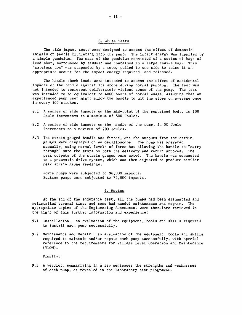
8. Abuse Tests
The side impact tests were designed to assess the effect of domesticanimals or people blundering into the pump. The impact energy was supplied bya simple pendulum. The mass of the pendulum consisted of a series of bags oflead shot, surrounded by sawdust and contained in a large canvas bag. This"careless cow" was suspended by a rope, pulled to one side to raise it anappropriate amount for the impact energy required, and released.
The handle shock loads were intended to assess the effect of accidentalimpacts of the handle against its stops during normal pumping. The test wasnot intended to represent deliberately violent abuse of the pump. The testwas intended to be equivalent to 4000 hours of normal usage, assuming that anexperienced pump user might allow the handle to hit the stops on average oncein every 100 strokes.
8.1 A series of side impacts on the mid-point of the pumpstand body, in 100Joule increments to a maximum of 500 Joules.
8.2 A series of side impacts on the handle of the pump, in 50 Jouleincrements to a maximum of 200 Joules.
8.3 The strain gauged handle was fitted, and the outputs from the straingauges were displayed on an oscilloscope. The pump was operatedmanually, using normal levels of force but allowing the handle to "carrythrough" onto the stops on both the delivery and return strokes. Thepeak outputs of the strain gauges were noted. The handle was connectedto a pneumatic drive system, which was then adjusted to produce similarpeak strain gauge readings.
Force pumps were subjected to 96,000 impacts.Suction pumps were subjected to 72,000 impacts.
9. Review
At the end of the endurance test, all the pumps had been dismantled andreinstalled several times and some had needed maintenance and repair. Theappropriate topics of the Engineering Assessment were therefore reviewed inthe light of this further information and experience:
9.1 Installation - an evaluation of the equipment, tools and skills requiredto install each pump successfully.
9.2 Maintenance and Repair - an evaluation of the equipment, tools and skillsrequired to maintain and/or repair each pump successfully, with specialreference to the requirements for Village Level Operation and Maintenance(VLOM).
Finally:
9.3 A verdict, sumiparizing in a few sentences the strengths and weaknessesof each pump, as revealed in the laboratory test programme.

- 12 -
10. Reporting
10.1 The first interim report was issued in February 1982, detailing the
results of Sections 1 to 6 for both batches of pumps, with early
indications from the endurance tests.
10.2 It was necessary to report several particular endurance problems to
individual pump manufacturers. In one case, the manufacturersubstantially re-designed the pumpstand, and supplied a sample to the new
design, to enable the endurance test to be completed.
10.3 The Final Summary Report was published in May 1983 as World Bank
Technical Paper No. 6 - "Laboratory Evaluation of Hand-Operated Water
Pumps for Use in Developing Countries."
10.4 This is the Final Technical Report, and gives details of the test
procedures and the results for the individual pumps.

- 13 -
2.3 Installation for Testing
The pumps are installed on the top floor of a purpose-built10 metre tower. They are arranged in batches of six, with a motorand tank for each batch.
The floor beneath the pumps houses the mechanical drives for theendurance tests. Beneath that, each deep-well pump is fitted with a headsimulation valve which is designed to simulate well depths down to 45 metres.
The level of water in the tank on the ground floor is maintainedby a pump and constant level device.
Pumps on Test -
Endurance drivemechanism
Head simulationvalves
Water tanks
Handpump Testing Tower

- 14 -
The exteror of th tower Soe oftheinsale pumps
_~~ -
, ~~~~~~~~~~~~~~~~~~~~~~~~~.,
_ -.. _. .*_ ,
The exterior of the tower Some of the installed pimpson the top floor
; | . wan*,--,
The endurance drive mechanisms Handle shock test

-15 -
2.4 Basic Pump Nomenclature
DEEP-WELL PUMPS SHALLOW-WELLSUCTION PUMP
Handle\ PumpHead Fulcrum
0 ConnectingHandle X Rod
Spout S L \ Pumpstand PUMPS AND
8 °, a Fulcrum -- l\XA
Base Spout P SpoutPlinth Plate Plunger
Check
Valve
Pump Rod
--.Rising Main_Drop Pipe - BELOW
Rotor or GROUND0 Cylinder Rising Main ASSEMBLY
Plunger Stator
~Foot Valve
. ~ -Strainer -
In response to comments received on Report No. 1, the following definitionswill be used throughout.
A shallow-well suction pump is one where the plunger is in the body of thepump, above ground. For practical purposes, the maximum operating depth ofthis type of pump is 7 metres.
A shallow or deep-well force pump is one where the plunger is below staticwater level, at the bottom of the rising main. Such pumps are self-priming.The maximum operating depth is limited only by the strength of the pump and itsoperator.

- 16 -
3. GENERAL OBSERVATIONS AND RECOMMENDATIONS
3.1 Observations
Literature
All pumps should be supplied with instructions for installation,
maintenance and use. Plenty of clear illustrations are of particular value
in overcoming language and literacy problems. In the majority of pumps the
pump rod must be cut accurately to length during installation. In very few
cases were adequate instructions provided by the manufacturer.
Skills required
All the pumps require basic mechanical skills for installation and
maintenance, some needing considerable expertise.
Installation
Many pumps require lifting tackle for installation and maintenance
because galvanised iron rising main is used. If uPVC or other plastic pipe
could be used, the below-ground assembly could be installed or removed withoutlifting tackle.
Baseplate sealing
With some pumps, extra care is needed during the preparation of
the base and subsequent installation to ensure an adequate sanitary seal.
Mounting Height
Many manufacturers give no indication of the correct height towhich the pumps should be installed. The best pump designs are those which
do not require a special pedestal built up on a wellhead. Pumps should
have an in-built design feature which ensures that they are mounted at the
correct height.
Spares
All the pumps may in time need manufacturer's spares, some of
which can be costly. However the cost per unit of a stock of spares will
fall the more pumps are installed in the field. Accent should be placed on
development of the VLOM concept with regionally produced spare parts if possible.
Two-person Operated Pumps
Rotary pumps which can be operated by two people may have certainadvantages. It may be necessary to investigate local cultural/sociological
factors to assess the likely problems of this in practice. Throughout the
Laboratory tests only one person was used.
Safety
Some manufacturers do not pay sufficient attention to the
avoidance of safety hazards, even where this involves only a simple design
change, i.e. long bolts with ragged ends, finger traps, tails of split pins.

- 17 -
Design Features
Handle: From observation of users operating reciprocating pumps,one potential cause of wear in the handle pivot could be eliminated by addinga "T" at the end of the handle where applicable. Cast iron is prone tobreakage and difficult to repair. Handles should be of resilient material,steel bar or tube, or wood where available.
Valves: Some manufacturers give insufficient attention to theamount of valve lift. It is often excessive which lowers efficiency andintroduces a risk of valves jamming open.
Pump rod Constraint: The test results suggest that where thedesign attempts to constrain the motion of the pump rod into a straightline, bending forces are generated which cause failure at the pump rodjoints. (It would be helpful to obtain information from the field on thispoint).
Glands: These are not an ideal method of sealing the pump rodwhere it passes through the pumpstand, particularly if also used as rodguides. Wear is inevitable and the subsequent leakage apart from the lossof sanitary seal, could produce difficulties if tank filling is needed.
Faecal Contamination: Manufacturers should, whenever possible,look at the designs of the outlet spout to ensure that users cannot seal offthe outlet with their left hand after defecating, to build up water in thebody of the pump.
Fasteners: Few manufacturers have considered rationalising thevariety of fasteners used on the pump. These could often be all one size ortype, therefore needing only one tool.
Discharge Valve: In view of the few applications where tankfilling facility is needed, the complication in pumpstand design that thisintroduces is unnecessary as a standard feature and often creates points ofweakness. See also Glands.
Multiple Plunger Seals
Several manufacturers incorporate two cup seals on their pumpplungers, possibly with the idea that the second one will provide a back-upseal in the event of failure of the first one, or perhaps to share the load.
Particularly in the case of leather cup seals, evidence obtainedfrom the laboratory endurance tests shows that the top of the lower sealdeforms inwards and becomes ineffective in the event of a top seal failure.
Unless clear evidence can be obtained from the field of the valueof the second seal, it is considered to be an unnecessary complication andthe plunger design can be simplified for only one seal.

- 18 -
Multiple Foot Valves
Unlike multiple cup seals, paired foot valves can share the work,
since both must open and close in unison. The pump will continue to work
when one foot valve has failed. However, we have evidence of one example
where this was a disadvantage : broken parts of the failed foot valve became
entangled in the plunger and severely damaged the cylinder.
Quality Control
All designs require a measure of quality control but some of the
more complicated pumps need very strict quality control in manufacture,
particularly in developing countries. Use of simple jigs and fixtures can
greatly help the quality control situation and ensure both correct original
construction and interchangeable replacement spares.
Efficiency
For most deep-well pumps, the efficiency at 25 or 45 metres is
generally markedly greater than at 7 metres depth. This occurs because the
relative contribution of friction to the total workload is greater at 7
metres than at the deeper settings. The effect is most pronounced for
helical pumps of the Mono/Moyno type.
VLOM
Although some of the pumps satisfy the requirements for VLOM quite
closely, none do so completely. Attention to the above points would go a
long way towards meeting the VLOM concept.

- 19 -
3.2 Recommendations from the 18 Pumps Tested
None of the pumps tested was satisfactory in every respect. Allthe designs represent some compromise between reliability, performance, easeof installation and maintenance, user convenience and so on.
The selection of the most appropriate pumps for community usedepends on the local conditions. In different applications, particularparameters will be of greater or lesser significance. It is therefore veryimportant to define these conditions before deciding which pumps to use.However, for most applications, out of the 18 pumps tested in Batches 1, 2and 3, we would expect the choice to be made from the following 9 pumps(given in alphabetical order):
Deep-well Pumps
Korat 608 A-1 Reliable below ground, potentially suitable for manufacturein developing countries with foundry skills, needs a smallchange to eliminate the safety hazard.
Maldev Pumpstand only, designed for 2.5 inch uPVC or galvanisediron rising main and for ease of maintenance. Robust andreliable, suitable for manufacture in developing countries.
Moyno 1V 2.6 Robust and reliable, awkward to operate, output low, butnot recommended for use at less than 20 metres depth.Unsuitable for manufacture in developing countries.
Nepta Easy for children to operate, very efficient, but should beredesigned below-ground to eliminate the spring.
Nira AF76 Robust for wells down to 20 metres, as a result of manyimprovements made by the manufacturer. Reasonably goodcompromise design.
Volanta Easy to maintain. Cables were unreliable, but manufacturernow supplies steel rods. Considerable potential formanufacture in developing countries.
Shallow-well Pumps
Ethiopia BP50 Self-priming, not a suction pump, thus very suitable fordrinking water. Awkward for children to operate, easy toinstall and maintain. Not very robust. Suitable formanufacture in developing countries.
New No.6 Suction pump, suitable for manufacture in developingcountries with foundry skills. High output, but needspriming with consequent danger of contamination. Needsattention to corrosion protection of plunger and check valve.
Rower Suction pump with high rate of delivery, very suitable forlow-lift irrigation though not recommended for drinkingwater. Easy to manufacture, install and maintain.

- 20 -
4. INDIVIDUAL PUMP EVALUATION
For each pump, the illustration and description are followed by
comments and the test results under the headings set out in the Test
Procedure.
Pump Lubrication
When the pumps were installed all moving parts were correctly
lubricated. During the course of the endurance test no further lubrication
was provided since it cannot be assumed that regular lubrication will occur
in the field. If any components failed in the endurance test requiring the
pumps to be dismantled, then correct lubrication was given on re-assembly.
Head Simulation Valve Setting for the Endurance Test
This valve was set either to operate at 45 metres or the greatest
depth recommended by the manufacturer for the operation of his pump,
whichever was the lower figure.
Endurance and Performance Stroke Speeds
For force pumps the endurance stroke speed was selected at 40 per
minute, as being the highest rate sustainable by a person to fill a 20 litre
container. In the performance test the pump rates included 50 strokes per
minute since this is humanly possible for a short duration.
For suction pumps a maximum speed of 30 strokes per minute was
selected for the endurance test, as operating above this speed produced
cavitation under the plunger. Accepting cavitation, the suction pumps
functioned at 40 strokes per minute, and this speed was therefore included
in the performance test.
In all cases the arc of handle movement was selected to be just
within the limit of the stops to avoid the risk of uncontrolled banging of
the handle, which was the subject of a separate abuse test.
User Trial
Marginal changes were made in the user trial of Batch 3 compared
with Batches 1 and 2. These have been explained in the Introduction to
Appendix I.

- 21 -
Abuse Tests - Handle Shock Load Test
This test was carried out at the specified endurance stroke speedfor 40 hours. Controlled shocks were provided on the handle stops with aforce determined from a user test where the handle was allowed to travelwith the normal level of effort on to the stops. Force pumps received96,000 shocks and suction pumps 72,000 shocks.
Requirements for maintenance and repair
The equipment, level of skill and personnel required forinstallation, maintenance and repair are illustrated by the followingsymbols:
Clamp Hacksaw Hand Tools Hexagon Key(s)
Lifting Pipe Flat Jointingtackle Wrench(es) Spanners Materials
Lubricant Threading Skilled Labourer(oil and/or Die(s) and Persongrease) Die Stock

- 22 -
Abi-Vergnet
I: X
I. IC

- 23 -
ABI-VERGNET ASM
1.1 Manufacturer Groupement Abidjan Industrie SNE Mengin
Address Boite Postale 343,Abidjan,Ivory Coast
1.2 Description The Abi-Vergnet is a hybrid pump working onhydraulic principles. There are no mechanicallinks between the above- and below-ground parts.
The Vergnet cylinder is a product of highmanufacturing technology. A flexible rubber tubeencased in stainless steel dilates and collapsesin response to a primary cylinder in the pumpstandto which it is connected by a plastic hose.When the flexible membrane expands, water is forcedto the surface through a second hose.
The pumpstand is partly cast-iron and partlyfabricated. The main handle bearings are compressedcarbon composite material. The primary cylinderinside the pumpstand column is a stainless steeltube. The primary plunger is machined from brassand uses a number of leather ring seals. The primarycylinder is replenished by water flowing in througha small hole in the part of the cylinder which isexposed by the plunger near the upper limit of itstravel.
1.3 Price $836 complete for 20 m depth.
2. INSPECTION
2.1 Packaging The pumps were packed in 2 wooden packing cases;one contained the down-well components and theother contained the pump head units. The hose wasdelivered in a large roll.
This packaging was considered very suitable forexport and for crude overland transportation.
2.2 Condition as On one sample the threads were damaged on the baseReceived of the pump head. In the second sample, the rubber
buffer in the primary plunger was too short, givingfree play in the connecting rod.
The pump pedestal base plates were distorted out offlat in both samples. The component parts of thehandles were not correctly aligned.
Abi-Vergnet Pump

- 24 -
2.3 Installation & In French. Comprehensive and quite well illustrated.
Maintenance Useful both for installation and subsequent
Information maintenance and repair.
3. WEIGHTS & MEASURES
3.1 Weights Pumpstand 60 kg (including handle)Cylinder: 9 kg
3.2 Dimensions Nominal cylinder bore: 58 mmActual pump stroke: 145 mmNominal volume per stroke: 383 mlDrop pipe size: 26 mm I/D x 32 mm O/DMaximum outside diameterof below-ground assembly 96 mm
3.3 Primary No significant taper or ovality was found in the
Cylinder Bore primary cylinder of either sample.
The surface roughness average (R ) was measured inthree places in a direction para!lel to the cylinderaxis.
The results are shown below:-
SAMPLE CYLINDER BORE ROUGHNESS AVERAGE (um)TEST 1 TEST 2 TEST 3 MEAN
1 Machined steel 0.56 0.58 0.58 0.57
2 Machined steel 0.63 0.58 0.60 0.60
Measured at 0.25mm cut-off
3.4 Ergonomic Measurements
HANDLE HEIGHT PLATFORM ANGULAR HANDLE VELOCITY HEIGHT
(1) 1-~-----.)- HEIGHT MOVEMENT LENGTH RATIO OF OF SPOUT
MAX(' MIN") (mm) OF HANDLE (mm) HANDLE (mm)
(mm) (mm) (degrees)
1150 340 0 63 775 5.2 610
(1) Measured without compressing any bump stops
Abi-Vergnet Pump

- 25 -
4. ENGINEERING ASSESSMENT
4.1 Materials of Construction
The materials used for the principal components are detailed below:
COMPONENT MATERIAL(S)
Pumpstand body & cap Cast iron top and capSteel body and baseplate
Handle Mild steelCylinder casing Stainless steelPumping element Rubber, with light alloy fittingsTop cap and valves Brass with stainless steel balls and
acetal fittingsPrimary plunger Gunmetal with leather sealsassemblyFoot valve Brass/gunmetal with stainless steel ball
and plastic shield
4.2 Manufacturing Techniques
The manufacturing techniques required to make the pump are listed below:
Above-ground Iron and gunmetal foundryAssembly Steel fabrication
Basic machining
This pumpstand demands basic skills in iron foundry and considerableskill in steel fabrication. It may be suitable for manufacture indeveloping countries where these skills exist. It would not be difficultto modify the pumpstand design for all-fabricated manufacture. The handlerequires careful jigging for welding.
Below-Ground Hot pressing of brassAssembly Light alloy foundry
Plastics mouldingMachiningWelding (of stainless steel)Specialised processes (pumping element)
The pumping element assembly demands advanced, specialised manufacturingtechniques, and a high degree of skill. It would be particularly unsuitablefor manufacture in a developing country.
Abi-Vergnet Pump
- 26 -
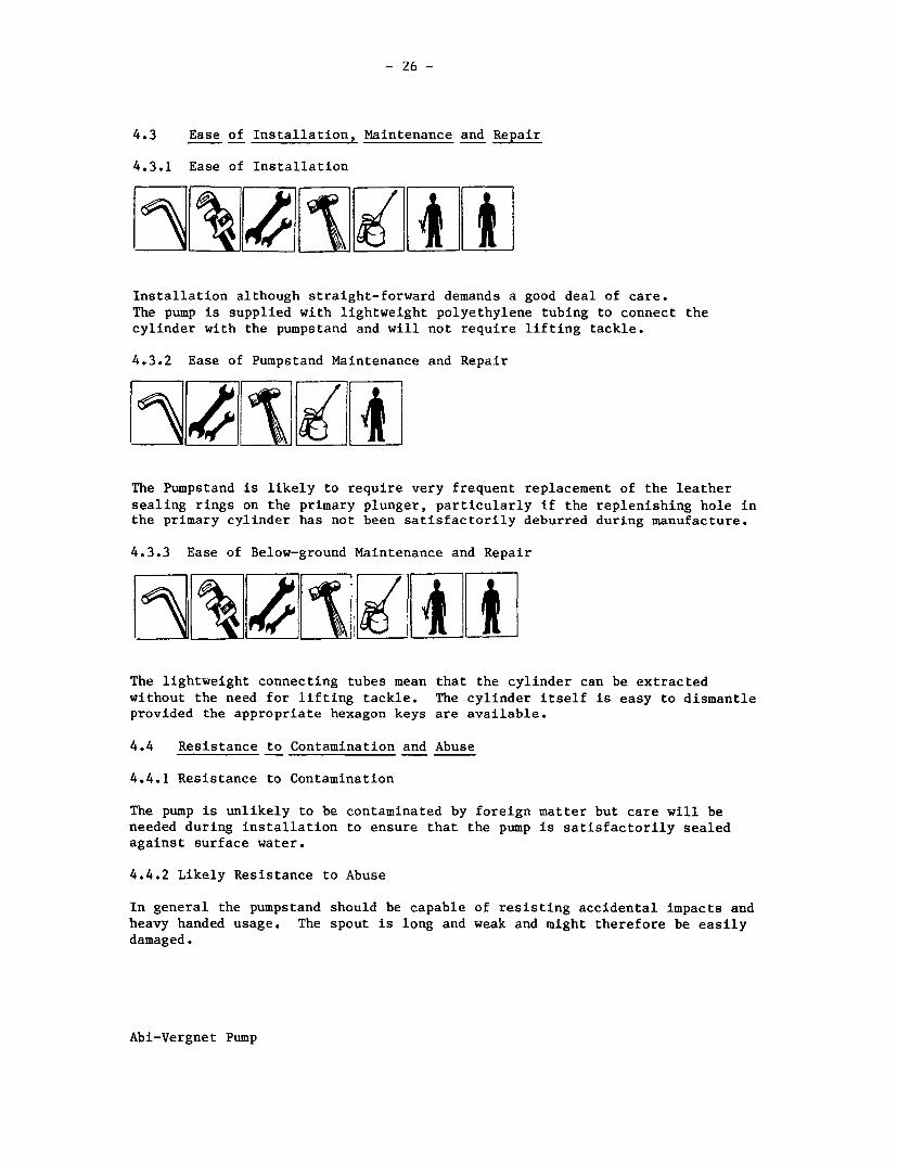
4.3 Ease of Installation, Maintenance and Repair
4.3.1 Ease of Installation
Installation although straight-forward demands a good deal of care.The pump is supplied with lightweight polyethylene tubing to connect thecylinder with the pumpstand and will not require lifting tackle.
4.3.2 Ease of Pumpstand Maintenance and Repair
The Pumpstand is likely to require very frequent replacement of the leather
sealing rings on the primary plunger, particularly if the replenishing hole inthe primary cylinder has not been satisfactorily deburred during manufacture.
4.3.3 Ease of Below-ground Maintenance and Repair
ALXkA�lk(4&The lightweight connecting tubes mean that the cylinder can be extracted
without the need for lifting tackle. The cylinder itself is easy to dismantleprovided the appropriate hexagon keys are available.
4.4 Resistance to Contamination and Abuse
4.4.1 Resistance to Contamination
The pump is unlikely to be contaminated by foreign matter but care will beneeded during installation to ensure that the pump is satisfactorily sealedagainst surface water.
4.4.2 Likely Resistance to Abuse
In general the pumpstand should be capable of resisting accidental impacts andheavy handed usage. The spout is long and weak and might therefore be easilydamaged.
Abi-Vergnet Pump

- 27 -
4.5 Potential Safety Hazards
There is a potential finger trap between the handle and the body of thepumpstand when the handle is at the bottom of its stroke.
4.6 Suggested Design Improvements
Flats should be machined on either side of the crankpin in the handle, toincrease the load bearing area for attaching the connecting rod.
The baseplate should be flat - it should either be stiffer or be pre-formed before welding to ensure flatness after welding.
The primary plunger seals should be made of a less soft material -polyethylene may be suitable - or standard proprietary seals may beavailable.
The replenishing hole in the primary cylinder should be deburred on theinside.
In the pumping element assembly, an effort should be made to rationalisethe various bolts, screws, 0-rings etc., to minimise the number ofdifferent parts.
It may be cost-effective to simplify the handle by eliminating the pressing- see sketch, below:
Abi-Vergnet Pump

- 28 -
5. PUMP PERFORMANCE
5.1 Volume Flow, Work Input and Efficiency
The description of the method can be found in the Test Procedure.
HEAD 7 m 25 m 45 m
Pumping Rate(strokes/min) 30 38 49 32 40 50 32 42 50
Vol/stroke (litres) 0.28 0.27 0.27 0.26 0.26 0.26 0.24 0.25 0.25
Work input/stroke (J) 127 130 139 185 194 211 262 250 286
Efficiency (%) 15 14 13 34 32 30 39 43 38
5.2 Leakage Tests
In the leakage test, no leakage was observed from the footvalve at 7, 25 and
45 metres heads.
6. USER TRIAL
Details of the organisation of this trial can be found in the TestProcedure.
Many users needed guidance to find an appropriate method of operation, but
then quickly became accustomed to operating the pump at a steady rhythm,
timing their efforts to coincide with the characteristics of the pump. Most
found the pump tiring to use because of the slow rate of delivery. The
handle height seemed satisfactory for a wide range of user heights.
7. ENDURANCE TESTS
A detailed description of the endurance test method can be found in the Test
Procedure.
General Comments
The pump was tested at 40 strokes/minute at a simulated head of 45 metres,
subsequently reduced to 20 metres.
The below-ground assembly completed the 4000 hour endurance test without
failure and remained in good working order at the end. By contrast thepumpstand was very unreliable.
Abi-Vergnet Pump

- 29 -
The original leather seals fitted by the manufacturer to the primary plungerwore out in 75 hours. They were replaced twice but it became clear that theaverage life of leather seals was approximately 80 hours. We believe theseals were damaged by the replenishing hole in the primary cylinder which hadnot been satisfactorily deburred during manufacture. The leather rings werereplaced by polyethylene seals machined from bar stock. The first set ofthese were worn out at the 1000 hour inspection and they were replaced by asecond set. During the second stage the bolt connecting the primary plungerrod to the handle pivot broke twice and was eventually replaced by a hightensile bolt. The handle to primary rod fulcrum had worn out after 1529 hoursand the handle assembly was replaced. At the inspection after the second 1000hour stage the second set of polyethylene primary plunger seals were worn out.
To experiment with alternative materials the polyethylene seals were replacedby others machined from acetal bar stock. These wore out in less than 600hours however, and a second set in less than 300 hours. They were replaced bytextile cord seals but these wore out in less than 200 hours. Polyethyleneseals were fitted once again to complete the endurance test and as beforethese wore out in approximately 1000 hours.
It is clear that the pumpstand needs substantial modification if itsreliability is to approach that of the below-ground components.
Breakdown Incidence
Breakdowns are shown in bold type.
Hburs: 1042 20B3 312 416775 l l l l
I 167 I 1087 19 I 2645 293 l l0 247 1306
Inspectimn Inspection l Inspection | Inspectiai Inspectionand ful and volume and volume and volume and volumeperformance flow test flow test j flow test flow testtest l l l l l l l
atwr s 1sealsuFE xe n to IAcetall Tmxtile owls FE primymn prkmry SWa, mrn primry rod primazy w= oit - sealplVeA r wom out fuiknm o Wrn reqid wa outou - replaced wo out om poltkwl eby polyethlUn Bblt bnlmd
cn~~~~ priimaryp
Is Pr'mnmy Metal pr1maryseas wnm out seas wrn outrep]aK: by replawd Blaiacetal tezrge Prum
Abi-Vergnet Pump

- 30 -
Details of the Endurance Test
Breakdowns are shown in bold type.
HOURS
75 ) Leather primary plunger seals worn out - examination with an optical
167 ) fibrescope revealed that a hole drilled in the primary cylinder to
247 ) replenish it from the main body of the pump had not beensatisfactorily deburred during manufacture. The leather seals were
replaced by sealing rings machined from high-density polyethylene bar
at 247 hours
Estimated Amount of water pumped to breakdown ..... less than 0.1 million litres
1042 Inspection after 1st 1000 hours:
a) Polyethylene plunger sealing rings worn out - replaced
b) Bolt securing plunger rod to handle loosec) One handle-to-pump-rod bush worn out, other loose -- the handle
was replaced by the second sampled) Spots of rust on plunger rod
The pumping depth was re-set to 20 metres to continue the test
Estimated Additional Amount of water pumped to breakdown...0.3 million litres
1087 ) Bolt securing plunger rod to handle broken - replaced at 1306 hours1306 ) by a high-tensile bolt
Estimated Additional Amount of water pumped to breakdown..< 0.1 million litres
1529 Handle to plunger rod bearings worn out and handle damaged - theoriginal handle was repaired using bearings from an older ABI pumpand re-used.
Estimated Additional Amount of water pumped to breakdown...0.1 million litres!
2083 Inspection after 2nd 1000 hours:
a) Polyethylene plunger sealing rings worn out - replaced by sealsmachined from polyacetal bar
b) Plunger slightly worn by contact with bore of primary cylinder
c) Rubber buffer in plunger collapsed -- replacedd) Localised rust inside pumpstande) Corrosion on end caps of pumping element
Estimated Additional Amount of water pumped to breakdown...0.3 million litres
Abi-Vergnet Pump

- 31 -
2645 ) Acetal plunger seals worn out - replaced by woven textile seals at2930 ) 2930 hours after increasing width of grooves in plunger to suit
Estimated Additional Amount of water pumped to breakdown...0.3 million litres
3125 Inspection after 3rd 1000 hours:
a) Textile seals worn out - replaced by wide polyethylene seals
b) Further corrosion of pumping element end caps
Estimated Additional Amount of water pumped to breakdown...< 0.1 million litres
4167 Final Inspection:
1 Seals Final set of polyethylene seals worn out
2 Plunger Plunger worn by contact with cylinder bore
3 Handle Some. wear of handle and bushes but still serviceable
4 Pumping Pumping element in good condition, including ball valvesElement
5 Corrosion Further rust inside pumpstandFurther corrosion of pumping element end caps
Estimated Additional Amount of water pumped to breakdown.. .0.3 million litres
Estimated Total Amount of Water Pumped in 4000 hours ...... 1.5 million litres
Leakage TestsVolume Flow Tests (litres) at 7 m (ml/min)
Strokes/min 30 40 50
New 25 m depth 0.26 0.26 0.26 <0.1New 45 m depth 0.24 0.25 0.25 <0.1After 1000 hours 45 m 0.11 0.16 0.16 <0.1After 2000 hours 25 m 0.19 0.20 0.20 <0.1After 3000 hours 20 m 0.16 0.19 0.18 <0.1After 4000 hours 20 m 0.06 0.06 0.08 <0.1
Pump Performance After Endurance
Not carried out due to continual replacement of seals.
Abi-Vergnet Pump

- 32 -
8. ABUSE TESTS
8.1 Side Impact Tests
Undamaged in both handle and body tests.
8.2 Handle Shock Tests
The pump completed the allotted 96,000 cycles without failure.
9. VERDICT
A sharp contrast was observed between the endurance of the pumpstand and of
the below-ground pumping element. The latter proved to be very reliable and
remained in good condition at the end of the test. The pumpstand wasunreliable and quite unsuitable for community water supply. However, this
pump is inherently simple to install and to maintain below-ground, and it is
therefore strongly recommended that a reliable VLOM pumpstand should bedeveloped.
Abi-Vergnet Pump

- 33 -
Polyethylene seals made to replace the original leather seals
r ;- - - 4
Handle bearings after 1529 hours
Abi-Vergnet Pump

- 34 -
Petro
I A~~~~ ~~~~~I, :
I~~~~~~~~~
e~-
iL )U0
C)~~~~~~~C

- 35 -
PETRO
1.1 Manufacturer WellDrill Systems AB
Address Tagenevagen 21,S-425 90 Hisings Karra,Sweden.
1.2 Description The Petro is an unconventional pump using thechanging volume of a stretched rubber hose toprovide the pumping action. The functions ofrising main and pump rod are combined in a singlecomponent and the cylinder assembly is anchoredin the well casing by an arrangement of twowedges faced with carborundum grit.
The pumpstand is fabricated from steel sectionsand is designed to ensure that the necessarypre-stress on the rubber hose is appliedautomatically during installation. Up to 10counterweight discs may be added to the handleto balance the weight of the below-groundassembly in a particular installation.
1.3 Price $465 per pump with 20 m below-ground assembly
2. INSPECTION
2.1 Packaging The pumps were packed in wooden packing cases;the pumpstands were well packed in separatecases.
The packaging was considered very suitable forexport and for crude overland transportation.
2.2 Condition as Received The 3/4 inch nominal bore rising main would notpass through the outer tube on both samples.A pivot pin was missing from one sample.
2.3 Installation & In English. Comprehensive and well-illustratedMaintenance by photographs and line drawings. Useful forInformation both installation and subsequent maintenance
and repair.
Petro Pump

36 -
3. WEIGHTS AND MEASURES
3.1 Weights Pump stand : 30.0 kg(excluding handle c/weights)Cylinder: 6.0 kgHandle Counterweights (each): 4.3 kgRising Main (per metre): 1.6 kg
3.2 Dimensions Actual pump stroke: 120 mmDrop pipe size: 0.75 inchWell diameter range 97 mm minimum
120 mm maximum
3.3 Cylinder Bore Not applicable
3.4 Ergonomic Measurements
HANDLE HEIGHT PLATFORM ANGULAR HANDLE VELOCITY HEIGHT
HEIGHT MOVEMENT LENGTH RATIO OF OF
MAX (1) MIN (1) (mm) OF HANDLE (mm) HANDLE SPOUT
(mm) (mm) (degrees) (mm)
1122 450 0 53 880 6.3 595 max.475 min.
(1) Measured without compressing any bump stops
4. ENGINEERING ASSESSMENT
4.1 Materials of Construction
COMPONENT MATERIAL(S)
Fulcrum upright SteelHandle and links SteelSpout SteelOuter guide tube SteelGuide assembly Glass-filled nylonPumping element Reinforced rubber with light alloy fittings
Clamp assembly Steel, glass-filled nylon, carborundum grit
Well cap SteelPivot pins Steel
Petro Pump

- 37 -
4.2 Manufacturing Techniques
The techniques required to manufacture the pump are listed below:
Above-ground Steel forming and weldingAssembly Machining - turning, drilling, milling etc.
The pumpstand demands well-developed skills in machining and steelfabrication. Specialised processes are not required, however, and thepumpstand may therefore be suitable for manufacture in some developingcountries.
Below-ground Machining - turning, drilling, milling etc.Assembly Plastics moulding
Specialised processes (pumping element)
The pumping element demands specialised manufacturing techniques andrigorous quality control. It would be particularly unsuitable formanufacture in developing countries.
4.3 Ease of Installation, Maintenance and Repair
4.3.1 Ease of Installation
We understand that the manufacturer considers lifting tackle to beunnecessary for installation at depths up to 45 m. However since the weightof a 45 m below-ground assembly would be some 78 kg excluding water, it may bevery difficult to manhandle. We recommend the use of simple lifting tackle.The manufacturer's installation manual is clear and well illustrated andinstallation should be straight-forward. It should not be difficult toensure that the anchor is secure in the well.
4.3.2 Ease of Pumpstand Maintenance and Repair
Servicing the pumpstand is very straightforward requiring only simplehand tools. The handle pivots may require occasional lubrication.
Petro Pump

- 38 -
4.3.3. Ease of Below-ground maintenance and repair
It should not be difficult to release the anchor provided the threadedcoupling at the bottom of the pumping element can be successfully detached.
In other respects below-ground maintenance will be similar to installation.
4.4. Resistance to Contamination and Abuse
4.4.1 Resistance to Contamination
The pump is unlikely to be contaminated by either surface water or foreign
matter.
4.4.3 Likely Resistance to Abuse
The pumpstand is generally robust and is likely to resist accidental damage to
the handle or the pump body. The spout might be easily damaged if abused
however.
4.5 Potential Safety Hazards
None
4.6 Suggested Design Improvements
Pumpstand:
A handle from square steel tube, with an on-site cast concrete counter-
weight, would be cheaper to manufacture than the all-steel assembly supplied.
However, the all-steel assembly will arrive at the wellhead ready for use,
whereas the installation crew would be required to cast a suitable concrete
counterweight.
If the steel counterweights are retained, it would be easier to turn a
recess in the first disc than to mill a slot.
The reason for the slot in the guide tube is not clear - if it could be
eliminated the 0-ring groove would be simplified.
Below-Ground Assembly:
The valve ball may be more efficient with a heavy core, but lead should
not be used.
Stainless steel pumping element end fittings, as proposed, would be
better than light alloy, as supplied.
Petro Pump

- 39 -
Plastic reducers are fitted in some connections, presumably to preventgalvanic corrosion couples. These could be eliminated if all parts werestainless steel.
A much simpler guide for the rising main would be adequate, a simple 3-legged moulding for example. If the present design is retained, thestress riser at the root of the legs should be eliminated.
The method of attaching the pumping element to the anchor must be modifiedto prevent seizure. This could be achieved by machining the male thread toa point with a corresponding plate welded over one end of the female socket.
5. PUMP PERFORMANCE
5.1 Volume Flow, Work Input and Efficiency
HEAD 7 25 45
Pumping Rate(strokes/min) 30 39 51 30 40 49 29 37 49
Vol/stroke (litres) 0.26 0.25 0.25 0.25 0.25 0.25 0.25 0.26 0.24
Work input/stroke (J) 74 78 86 112 120 123 178 202 201
Efficiency (%) 23 22 20 54 50 49 61 57 53
The description of the method can be found in the Test Procedure.
5.2 Leakage Tests
No leakage was observed from the foot valve at 7, 25 or 45 m heads.
6. USER TRIAL
Details of the organisation of this trial can be found in the TestProcedure. Most users seemed to operate this pump without difficulty,but many found it tiring because of the low rate of delivery.
Petro Pump

- 40 -
7. ENDURANCE
A detailed description of the endurance test method can be found in the
Test Procedure.
General Comments
The pump was tested at 40 strokes/minute at a simulated head of 45 metres.
This pump proved to be a good deal more reliable than the Petro tested for the
ODA in 1978/9.
The pump completed the first three 1000 hour stages without failure. However
the down-hole anchor could not be released for inspection of the pumping
element at the end of the third 1000 hour stage. Although given three full
turns the pumping element sprang back. As it was not possible to free the
anchor from the well top, the manufacturer was contacted by telephone for
advice and permission to remove the bottom section of the well. With the
bottom section removed, the anchor was released easily by pulling down on the
wedge. The thread on the anchor wedge rod was found to have locked in the
socket. When released the stainless steel threads were found to have seized.
This could present a very serious problem in the field where access to the
pumping element from below would be impossible.
The manufacturer agreed that we should try to use the same pumping element to
complete the endurance test. The element showed no signs of distress other
than slight flattening induced by twisting.
After 3634 hours the outflow from the pump was reduced to approximately 30% of
the original volume flow due to a split in the pumping element. This is
likely to have been caused by twisting the pumping element when attempting to
release the down-hole anchor for inspection after the third 1000 hour stage.
A new pumping element was fitted and the endurance test was completed with the
original down-hole anchor.
Breakdown Incidence
Breakdowns are shown in bold type.
Hours 1062 2112 3127 3644 4169
Inspection Inspection Inspection Inspection i Inspection
and full and volume and volume and volume Pumping and volume
performance flow test flow test flow test element flow test
test I splitPumpingelementseized inanchor.Anchor couldnot be released
Petro Pump

- 41 -
Details of the Endurance Test
Breakdowns are shown in bold type.
HOURS
1062 Inspection after 1st 1000 hours:
a) Noticeable free play in all fulcrum points of pumpstandb) Pipe polished in region of guidec) Anchor slightly displaced - refitted in wellcasingd) Slight rust on cylinder anchor
2112 Inspection after 2nd 1000 hours:
a) Slightly increased free play in pumpstand fulcrum pointsb) Pipe further polished in region of guidec) Noticeable corrosion on alloy end caps of pumping element
3127 Inspection after 2nd 1000 hours:
a) Pumping element anchor could not be released from above - it wasreleased for inspection from below but this would be impossiblein the field. The thread at the top of the anchor had picked-upin the fitting at the bottom of the pumping element. Thepumping element had been distorted by twisting in attempting torelease the anchor. In consultation with the manufacturer, thetest was continued with the original pumping element.
b) Slightly increased free play in pumpstand fulcrum pointsc) Ball valves marked by their seats
Estimated Additional Amount of water pumped to breakdown ..... 2.3 million litres
3644 Pumping element split - as a result of the damage sustained bytwisting in trying to release to anchor for inspection after the 3rd1000 hours - replaced by the element from the second sample.
Estimated Amount of water pumped to breakdown ............. 0 .4 million litres
Petro Pump

- 42 -
4169 Final Inspection:
1. Pumpstand Further free play in pumpstand fulcrum points;outer connecting links worn and could bedisconnected on the upward stroke of the handle
2. Guide Worn but still serviceable
3. Pumping Replacement in good conditionElement
4. Corrosion Slight corrosion on pumping element end fittingsand rust spots on rising main where guide hadrubbed through the zinc coating
Estimated Total Amount of Water Pumped in 4000 hours ...... 2.7 million litres
Leakage TestsVolume Flow Test at 45 m (litres) at 7 m (ml/min)
Strokes/min 30 40 50
New 0.25 0.26 0.24 <0.1
After 1000 hours 0.24 0.24 0.24 <0.1
After 2000 hours 0.29 0.29 0.29 <0.1
After 3000 hours 0.30 0.30 0.30 <0.1
After 4000 hours 0.27 0.27 0.28 <0.1
Pump performance was not remeasured after endurance because the pumping
element had been replaced.
8. ABUSE TESTS
8.1 Impact Tests
Undamaged in both handle and body tests.
8.2 Handle Shock Test
The pump completed the allotted 96,000 cycles without failure.
Petro Pump

- 43 -
9. VERDICT
This Petro pump proved to be much more reliable than the sample tested in1979/80 for the Overseas Development Administration. However, the resultsof this later test suggest that the anchor may not be suitable forunsupported uPVC well-casings and may also be difficult to dislodge forbelow-ground repairs. The method of attaching the pumping element to theanchor must be modified to prevent seizure.
The pumpstand may be suitable for manufacture in a developing country but thepumping element demands very specialised manufacturing skills.
Further work by CATR, carried out as a separate project, to investigate theeffect of using the anchor in unsupported uPVC pipe has confirmed that thisis inadvisable and that alternative arrangements should be made.
Petro Pump

- 44 -
Funymaq
0
~~~~~~~~~~~~~~~~~~~~~~~,~~~~~~~~~~~~~~~~~~~~~g
I ..- '
A X

- 45 -
FUNYMAQ
1.1 Manufacturer Funymaq, Honduras - supplied by the GeorgiaInstitute of Technology
Address Georgia Institute of Technology,Engineering Experimental Station,Atlanta,Georgia 30332,U.S.A.
1.2 Description This pump is a derivative of a deep-well design fromAID/Battelle for manufacture in developingcountries. The pumps tested were made in Honduras.The pumpstand is mostly cast iron though thecolumn is a length of steel tube threaded at eachend. It features a crosshead mechanism to guidethe top of the pump rod.
The cylinder design is conventional except thatuPVC tube is used in place of the more usualseamless brass tube, with cast iron end caps. Twoleather cup seals are used on the plunger. Twofoot valves are fitted. The upper foot valve inthe base of the cylinder is a simple flap ofleather with a cast iron weight. The lower footvalve is a proprietary Simmons item.
Neither rising main nor pump rods were supplied withthe pumps.
1.3 Price Not supplied
2. INSPECTION
2.1 Packaging The pumps were packed into an open-slatted woodencase and wired into position.
The pumpstand connecting rods were placed in thepump bodies and not secured. One fell through thebottom slats in transit and was bent. One handlewas protruding from the side of the case.
The packing cases were strong, but their slattedconstruction made them unsatisfactory for export orfor crude overland transportation. The casesshould at least have solid bases.
Funymaq Pump

- 46 -
2.2 Condition as The pump tops would not fit the bodies - the holesReceived were drilled in the wrong positions - and the holes
in the pump cap did not provide sufficient room forthe bolt heads. The handles were stiff to operate.One guide block was seized on its pin. The topsection of one pump was not tight on the centresection.
One pump rod was bent in transit. Cast iron partshad not been flushed of casting sand. There wassome evidence of porosity in some of the ironcastings.
2.3 Installation and No literature was supplied with the pump.MaintenanceInformation
3. WEIGHTS & MEASURES
3.1 Weights Pump Stand: 51.0 kg (including handle)Cylinder: 8.0 kg (including Simmons foot
valve)
3.2 Dimensions Nominal cylinder bore: 70 mmActual pump stroke: 190 mmNominal volume per stroke: 731 mlDrop pipe size: 1.25 inch *Pump rod diameter: 7/16 inch *Outside dia. of below- 105 mmground assembly
Maximum usable cylinderlength: 320 mm
* Not supplied but designed for these sizes.
It is interesting to note that there are significant differences betweenthis pump and the Sumber Banyu although both pumps were derived from samedesign. In particular the castings of the Funymaq were a good deal heavier.
Funymaq Pump

- 47 -
3.3. Cylinder Bore No significant taper or ovality was found in eitherof the two samples.
The surface roughness average (Ra) was measured inthree places in a direction parallel to thecylinder axis.
SAMPLE CYLINDER BORE ROUGHNESS AVERAGE (um)
TEST 1 TEST 2 TEST 3 MEAN
1 Extruded uPVC 1.5 1.7 1.4 1.5
2 Extruded uPVC 1.5 1.5 2.0 1.7
Measured at 2.5 mm cut-off
3.4 Ergonomic Measurements
HANDLE HEIGHT PLATFORM ANGULAR HANDLE VELOCITY HEIGHTHEIGHT MOVEMENT LENGTH RATIO OF OF
MAX(') MIN"1 ) (mm) OF HANDLE (mm) HANDLE SPOUT(mm) (mm) (degrees) (mm)
1310 280 0 90 730 5.8 470
(1) Measured without compressing any bump stops
4. ENGINEERING ASSESSMENT
4.1 Materials of Construction
COMPONENT MATERIAL(S)
Pumpstand top Cast ironPumpstand column 2 iron castings, 1 steel pipeand spoutHandle Cast ironFulcrum link Cast ironHandle fulcrum bushes Hardened steel )ApproximatelyHandle fulcrum pins Hardened steel )50 Rockwell CConnecting rod SteelEye Cast ironCylinder PVC body with cast iron end capsPlunger assembly Cast gunmetalCup seal LeatherFoot valve in cylinder Cast iron with leather flapSimmons foot valve Cast gunmetal with rubber seal
Funymaq Pump

- 48 -
4.2 Manufacturing Techniques
The techniques required to manufacture the pump are listed below:
Above-Ground Iron foundryAssembly Simple machining
Basic skills in iron foundry and machining are required, but careful qualitycontrol is essential to ensure smooth operation of the handle assembly andinterchangeability of parts for maintenance or repair. It is essential thatthe handle fulcrum pins and bushes are hardened. The pumpstand would besuitable for manufacture in developing countries with the appropriate skills,provided that the necessary quality control could be assured.
Below-ground Iron and gunmetal foundryAssembly Simple machining
Leatherwork
Basic skills in foundry work and machining are required. The cylinder would
be suitable for manufacture in many developing countries.
4.3 Ease of Installation, Maintenance and Repair
4.3.1 Ease of Installation
The Funymaq requires a substantial complement of tools and equipment and a
good deal of skill or experience to install it. Lifting tackle would not berequired if plastic rising main could be used.
4.3.2 Ease of Pumpstand Maintenance and Repair
The pumpstand is likely to require frequent lubrication of the handle andfulcrum link pivots. Eventually these components will need to be replacedbut most tasks are easy, requiring only spanners and pliers, though a driftand hammer may be needed to remove the pivot pins.
If our samples were representative of normal production then replacementparts may not be interchangeable with original components, possibly makingon-site repair impossible.
Funymaq Pump

- 49 -
4.3.3 Ease of Below-ground Maintenance and Repair
The cylinder is likely to require frequent attention to the leatherfootvalve and possibly to consequent damage to the cylinder or breakages ofthe pump rod. Below-ground repairs require removal of the complete below-ground assembly.
4.4 Resistance to Contamination and Abuse
4.4.1 Resistance to Contamination
The spout should be modified to prevent possible faecal contamination.The pump is sealed against surface water but could be contaminated throughthe connecting rod hole. The connecting rod is a poor fit in the pump top.
4.4.2 Likely Resistance to Abuse
The split pins are easy to remove and there are no locking fixings.Otherwise the pumpstand is generally robust.
4.5 Potential Safety Hazards
There are a number of potential finger traps around the handle fulcrummechanism and the guide blocks.
4.6 Suggested Design Improvements
A handle in a more resilient material than cast iron, such as steel orwood, where available, would be easier to repair.
The flanges on the pumpstand body and pumpstand cap should be enlarged toallow sufficient clearance for the heads of the fixings.
The check valve in the base of the cylinder should be omitted, or itsquality should be improv'ed and the proprietary foot valve omitted.
The spout should be vented or scalloped to prevent faecal contamination.
It is recommended that the design of the handle fulcrum be simplified andthe crosshead mechanism eliminated.
Funymaq Pump

- 50 -
5. PUM? PERFORMANCE
5.1 Volume Flow, Work Input and Efficiency
The description of the method can be found in the Test Procedure.
HEAD 7 m 25 m 45m
PumpingRate (strokes/min) 29 38 51 20 29 37 21 30 37
Vol/stroke (litres) 0.69 0.70 0.70 0.69 0.69 0.69 0.68 0.69 0.68
Work input/stroke (J) 125 134 134 261 277 304 404 459 468
Efficiency (%) 37 35 35 64 61 55 74 66 64
5.2 Leakage Tests
The measured leakage from the foot valves was not significant, i.e. less
than 0.1 ml/min, at 7, 25 and 45 metre heads.
6. USER TRIAL
Details of the organisation of this trial can be found in the Test
Procedure.
Most users seemed to operate the pump without difficulty. Many muscle
groups could be called into play without exaggerated body movements.
7. ENDURANCE
A detailed description of the endurance test method can be found in the
Test Procedure.
General Comments
The pump was tested at 40 strokes/minute at a simulated depth of 30 m.
The Funymaq pump proved to be much more durable than the Sumber Banyu pump
tested in 1981/82, although both pumps were derived from the same design.
In particular the handle pivots which had caused so much trouble in the
Sumber Banyu pump endured throughout the test on the Funymaq. However, like
the Sumber Banyu, the flap type leather foot valve broke away, in this case
after 3127 hours. The pump continued to work because the Simmons foot valve
supported the column of water, but the broken parts of the foot valve became
entangled in the plunger, bent the pump rod and caused severe damage to the
cylinder bore. It is strongly recommended that the flap type valve in the
base of the cylinder should be omitted, or its quality should be much
improved and the proprietary foot valve omitted.
Funymaq Pump

- 51 -
Breakdown Incidence
Breakdowns are shown in bold type.
Hours: 1062 2112 3127 41690
I~~~~~~~~~~~~ _I~~~~~~~~~~~~~~~
Inspection Inspection Inspection Inspection Inspectionand full and volume and volume and volume and fullperformance flow flow flow performancetest I test
Foot valve flapbroken away,pump rod bent,severe damage tocylinder bore
Details of the Endurance Test
Breakdowns are shown in bold type.
HOURS
1062 Inspection after 1st 1000 hour stage:
a) Slight wear in handle bearings and guide blocksb) Spots of rust on cylinder end caps and plunger rodc) Upper, leather foot valve appeared to be no longer functional and
had been deformed into a constant, open position
2112 Inspection after 2nd 1000 hours:
a) Slight increase in wear in handle bearings and guide blocksb) Larger spots of rust on cylinder end caps and considerable
corrosion on plunger rodc) Upper, leather foot valve redundant
Funymaq Pump

- 52 -
HOURS
3127 Inspection after 3rd 1000 hours:
a) Severe damage to cylinder bore caused by parts of leather foot
valve which had broken away and become entangled in the plunger.The plunger rod had bent and the cylinder bore was deeply scoredas a result. The cylinder assembly was replaced by the secondsample.
b) Slight increase in wear in handle bearings and guide blocks
c) Further corrosion of cylinder end caps and plunger rod
Estimated Amount of water pumped to breakdown . ..... 4.4 million litres
4169 Final Inspection
1 Cylinder Replacement cylinder in good condition
2 Bearings Considerable wear in handle bearings and guide blocks
but all still servicable
3 Pumpstand Hole in pumpstand top enlarged by connecting rod
4 Corrosion Considerable corrosion of cylinder end caps andplunger rod, latter particularly around joint with
plunger body
Estimated Total Amount of Water Pumped in 4000 hours ...... 6.7 million litres
Leakage Tests
Volume Flow Tests at 25 m (litres) at 7 m (ml/min)
Strokes/min 30 40 50
New 0.69 0.69 0.69 <0.1
After 1000 hours 0.68 0.68 0.68 (0.1
After 2000 hours 0.66 0.68 0.66 0.2
After 3000 hours 0.54 0.59 0.61 <0.1
After 4000 hours 0.70 0.70 0.70 <0.1
The performance test was not repeated after the endurance test because the
cylinder had been replaced. The results would therefore not have been
comparable with the original performance data.
8. ABUSE TESTS
8.1 Side Impact Tests
Undamaged in both tests: body tended to turn on thread at joint with
pumpstand column in handle test.
Funymaq Pump

-53 -
8.2 Handle Shock Test
After 89,000 cycles, the top of the pumpstand had worked loose on its threadat the connection with the column, resulting in a leak. The thread waseasily tightened and the pump remained in working order.
9. VERDICT
Different results were obtained for this Funymaq pump from Honduras than forthe similar Sumber Banyu pump from Indonesia, although both pumps werederived from the same AID/Battelle design. In particular, the hardenedhandle fulcrum pins and bushes endured throughout the test, and the lift ofthe plunger valve and its location were better.
The leather foot valve is worse than redundant because it can break away anddamage the plunger while the lower foot valve continues to support thecolumn of water in the rising main. The damage is therefore worse than itwould be if only one foot valve were fitted.
It is potentially suitable for community water supply, and for manufacturein developing countries with established iron foundry skills and effectivequality control.
Funymaq Pump

- 54 -
Maldev
I
I I
I I
I I
I I I
D I a

- 55 -
MALDEV
1.1 Manufacturer Petroleum Services (Malawi) Ltd.
Address Box 1900,Blantyre,Malawi.
1.2 Description At present, the Maldev consists of an above-groundassembly only. The pump was tested with a prototypebelow-ground assembly designed by Ken McLeod andlater with a Funymaq cylinder assembly.
The Maldev pump head was designed and made inMalawi, initially with ODA assistance, for use withconventional reciprocating deep-set cylinders. Itis fabricated from steel sections and the pedestalis intended to be concreted-in at the well head.The height and dimensions of the mounting flangeare identical to the India Mk II pump. The handlebearings are sealed ball races. It is designed toallow a 2.5 inch diameter plunger to be extractedwithout the need to dismantle the pumpstand. Thehandle is offered in various lengths to compensatefor operating depth and cylinder size.
1.3 Price Not known - Sample supplied by Department of Lands,Valuation & Water, Lilongwe, Malawi
2. INSPECTION
2.1 Packaging The pump heads were fixed into one wooden case whichwas then filled with cotton waste. The mountingflanges were loose in the case. The pedestal waspacked in another case.
The packaging was considered very suitable forexport and for crude overland transportation.
2.2 Condition as Slight distortion on the flanges of one pumpheadReceived unit. Paint was peeling off the other sample.
2.3 Installation and None supplied with the pump. However theMaintenance techniques of installation and maintenance hadInformation been demonstrated to CATR personnel by DLVW staff
in Malawi.
Maldev Pump

- 56 -
3. WEIGHTS and MEASURES
3.1 Weights Pumpstand complete: 51.1 kg
3.2 Dimensions Not applicable
3.3 Cylinder Bore Not applicable
3.4 Ergonomic Measurements
HANDLE HEIGHT PLATFORM ANGULAR HANDLE VELOCITY HEIGHT( HEIGHT MOVEMENT LENGTH RATIO OF OF
MAX (1) MIN () (mm) OF HANDLE (mm) HANDLE SPOUT(mm) (mm) (degrees) (mm)
Prototype sample1500 605 0 75 745 5.0 670
Production sample1550 600 0 89 650 5.5 670
(1) Measured without compressing any bump stops
4. ENGINEERING ASSESSMENT
4.1 Materials of Construction
COMPONENT MATERIAL(S)
Upper body and cap Steel tube and plate
Handle Steel bar and plateBearings Sealed ball racesHanger SteelPedestal Steel tube and plate
4.2 Manufacturing Techniques
The manufacturing techniques required to make the pump are listed below:
Simple but heavy steel fabricationSkilled weldingSimple turning, drilling and threading
The Maldev has been designed for manufacture in a developing country.
Both the fabrication and machining are straightforward, and no specialised
processes are required. However, considerable skill in welding is demanded,
and careful quality control is essential. It is suitable for manufacture in
developing countries, but potential manufacturers must be carefully
selected.
Maldev Pump

- 57 -
4.3 Ease of Installation and Maintenance
4.3.1 Ease of Installation
Installation of the pumpstand is generally straight-forward. Lifting tacklewill also be required to cope with the weight of the below-ground assemblyunless plastic rising main is used. The pedestal is concreted in at thewellhead around the well casing and the top of the pumpstand assembly can beinstalled with the handle pre-assembled. Some care is needed to ensure asatisfactory water-tight joint between the rising main and the pumpstand,but otherwise assembly is straight-forward and requires only basic skills.
4.3.2 Ease of Pumpstand Maintenance and Repair
The pumpstand is generally robust and unlikely to require frequentmaintenance, however more frequent attention may need to be given to thejoint between the rising main and the pumpstand to keep it watertight.
4.4 Resistance to Contamination and Abuse
4.4.1 Resistance to Contamination
Very good. The pumpstand is normally installed with a 3 m long deliverypipe to minimise the possibility of spilled water contaminating the wellhead.
4.4.2 Likely Resistance to Abuse
The pumpstand is generally very robust. The T-handle is intended to preventusers applying side forces to the handle bearings.
4.5 Potential Safety Hazards
None
Maldev Pump

- 58 -
4.6 Suggested Design Improvements
The outlet pipe socket should be placed a little higher on the body of thepump to avoid the need to cut the joint flange. A small triangular strutmay help to control the angle of the outlet pipe.
To avoid the potential manufacturing problems of alignment of the fourhandle flange plates, two thicker plates may be sufficiently strong andwould be easier to align in manufacture.
If two rather than four handle flange plates are used, the handle bearingball races might be replaced by bushes of a suitable engineering plastic.
A welded nut should replace the threaded hole to retain the top cap, and the
bolt should be the same size as those used for the flange fixings.
Anaerobic adhesive (e.g. Loctite Bearing Fit) should be considered to retainthe handle bearings, to eliminate fitting problems if ball races are used.
The hanger should be designed toremove the potential tolerance -flis '/z NT "NIPS'problem arising out of variablethickness of the bearing retainingnuts. On one side of the bearingat least, a machined shoulder couldbe provided on the pin.See illustration, right:
AW / AQI,qtoULbL OJT N
EEX | q 6 FACE OF
The hanger need not berounded off at the topand could be designedto eliminate the needfor the central slot.
See illustration, left.To reduce, and potentiallyto eliminate, distortion ofthe flange plate, it shouldbe cut as a square, with thecorners trimmed to avoid anyL RLUeEZNIPSTIE safety hazard. The existing
fixing hole centres couldbe retained.
Maldev Pump

- 59 -
5. PUMP PERFORMANCE
5.1 Volume Flow, Work Input and Efficiency
The description of the method can be found in the Test Procedure.
HEAD 7 m 25 m 45m
Pumping Rate(strokes/min) 29 41 48 20 30 37 20 30 37 45
Vol/stroke (litres) 0.47 0.48 0.48 0.52 0.51 0.52 0.46 0.51 0.50 0.48
Work input/stroke (J) 53 55 59 179 185 193 253 271 268 273
Efficiency (%) 60 59 55 70 67 66 80 82 82 76
These results were obtained from the prototype head with an experimental
'McLeod' type cylinder as the below-ground assembly.
6. USER TRIAL
Details of the organisation of this trial can be found in the Test Procedure.
The pump was generally well-liked by users. All users stood behind the
pump and grasped the T-handle with one hand on each side. Some children
and small women found the handle rather too high; to achieve a full stroke,
small users had to change their action, from pull to push, in mid-stroke.
7. ENDURANCE
General Comments on the Pump Head
The pump was tested at 40 strokes per minute at a simulated head of 30 metres.
Several problems were encountered with the original seal between the risingmain and the pumpstand. After 2188 hours the rising main was not secure in
the pumpstand and slipped through the seal on each upstroke of the cylinder.
It was re-tightened but thereafter persistent leaks occurred until the seal
was replaced by the later type now supplied with the pump. Even then a
persistent slight leak remained between the rising main and the pumpstand
until the end of the test.
The original endurance test sample was not representative of current
production. One of the handle bearings broke up during the first 1000
hours. Subsequent examination revealed that the ball race had been damaged
while being hammered into its housing. The endurance test was therefore
restarted using a newer pumpstand, to which the comments in this report refer
exclusively. This sample was tested using a Funymaq cylinder as the below-
ground part.
Maldev Pump

- 60 -
Breakdown Incidence
Breakdowns are shown in bold type.
lburs: 1021 2096 3131 41370 I I 2188 2409 l
l l l l 2426 ll l l l 2918 l
i ~ ~ ~ ~ ~~I I I I III ~ ~ ~~~~I I I i II
Inspection Inspection Inspection I Inspection InspectionRisng =EinMt smein pwpstad
Tk-i anund rising mnminde pumpstmd
Details of the Endurance Test
Breakdowns are shown in bold type.
HOURS
1021 Inspection after 1st 1000 hours:
a) Leaking joint between rising main and pumpstand due to distortionof the joint flanges -- sealed by flexible gasket compound
b) No significant corrosion
2096 Inspection after 2nd 1000 hours:
a) Slight leak at joint between rising main and pumpstandb) No significant corrosion
2188 Rising main not secure in pumpstand - the grip of the sealing collaron the rising main was insufficient to resist the upward frictionalforce of the plunger seal on the upstroke: as a result the entirerising main and head simulation valve rose on each stroke. Thesealing collar was replaced.
Estimated Amount of water pumped to breakdown ............. 2.6 million litres
2409 ) Continuing leaks around sealing collar between rising main and2426 ) pumpstand.2918 )
Maldev Pump

- 61 -
Estimated Additional Amount of water pumped to breakdown... .0.3 million litres
3131 Inspection after 3rd 1000 hours:
a) Slight leak at joint between rising main and pumpstandb) Slight free play in handle bearingsc) No significant corrosion
4137 Final Inspection
1. Joint Slight leak at joint between rising main and pumpstand
2. Bearings Considerable free play in handle bearings
3. Corrosion No significant corrosion
Estimated Total Amount of Water Pumped in 4000 hours ...... 5.0 million litres
8. ABUSE TESTS
8.1 Side Impact Tests
Undamaged in both handle and body tests.
8.2 Handle Shock Tests
The pump completed the allotted 96,000 cycles without failure.
9. VERDICT
A robust pumpstand but still requiring some development of the method offixing the rising main, clearly designed to use appropriate manufacturingskills with VLOM in mind. Although capital-intensive manufacturing facilitiesare not necessary, strict quality control is essential to achieve a reliableproduct.
There is scope for reductions of both cost and difficulty of manufacture byusing plastic plain bearings rather than ball races in the handle andhanger.
Polyacetal bearings have therefore been made for both these applications andfield trials are in progress. Good preliminary results have been receivedand further samples have been installed on heavy usage pumps to gain furtherexperience.
Once the principle has been thoroughly tested out successfully, changes canbe made to the design which will simplify the manufacture, and reduce thecost of this head.
Maldev Pump

4\~~~~~~~~~~~~~~~~~~~~ \oe
,~~~~~~~~~~~~~~~~~~~~~~~~~~~~~~~~~~~~~~~~~w A%\
0
3~~~~~~~~~~~~~~~C,4
'IO ~ ~ ~ ~ ~ ~ ~ ~ ~ ~ 7

- 63 -
ROWER
1.1 Manufacturer Mirpur Agricultural Workshop Training School
Address c/o The World Bank,222 New Eskaton RoadPO Box 97,DHAKA,Bangladesh.
1.2 Description The Rower pump is a high capacity low-lift pumpdesigned for irrigation, made in Bangladesh.The pump is fitted with a surge chamber. Thecylinder is a simple length of extruded uPVC tubewith heat swaged ends. The operator pulls directlyon the plunger rod by means of a T-handle. Theplunger is fitted with a single leather cup washerand simple rubber flap valves cut from tyre innertubes are used for both the plunger valve and checkvalve.
The pump is normally embedded in earth for supportand protection, as shown, or alternatively may besupported by a smaller earth bank and protected bystrips of bamboo bound around the cylinder. It isusually operated in a seated position.
1.3 PRICE $13.50, local price in Bangladesh.
2. INSPECTION
2.1 Packaging The pumps were packed in a hessian sack and card-board box. The two pump units were tied togetherwith spare parts inside the pump cylinder. Thesurge chamber was packed in a cardboard box.
The samples were delivered by hand, and we cannottherefore comment on the suitability of packagingfor export and for crude overland transportation.
2.2 Condition as Both pumps were received in good working order.Received
2.3 Installation & Engineering drawings were supplied with the testMaintenance samples: these were useful but not suitable asInformation an alternative to an installation and maintenance
manual.
Rower Pump

- 64 -
3. WEIGHTS & MEASURES
3.1 Weights Pumpstand complete : 3.5 kg
3.2 Dimensions Nominal cylinder bore: 54 mm
Actual pump stroke (max): 980 mm
Nominal volume per stroke: 2.24 litres
Drop pipe size: 1.5 inch
Maximum outside diameter of
below-ground assembly: 59 mm
3.3 Cylinder Bore No significant taper or ovality was found in either
of the two samples.
The surface roughness average (Ra) was measured in
three places in a direction parallel to the cylinder
axis.
SAMPLE CYLINDER BORE ROUGHNESS AVERAGE (um)TEST 1 TEST 2 TEST 3 MEAN
1 Extruded uPVC 0.55 0.50 0.60 0.55
2 Extruded uPVC 0.60 0.55 0.60 0.58
Measured at 0.25mm cut-off
3.4 Ergonomic Measurements
HANDLE HEIGHT ANGULAR HEIGHTMOVEMENT OF
MAX( 1 ) MIN(') OF HANDLE SPOUT(mm) (mm) (deg) (mm)
1225 840 0 790
(1) Measured without compressing any bump stops
The pump is normally buried in an earth mound to provide support and
protection.
Rower Pump

- 65 -
4. ENGINEERING ASSESSMENT
4.1 Materials of Construction
COMPONENT MATERIAL(S)
Handle Fabricated steel with injection moulded plasticspacers.
Angled Connector Galvanised steel pipeCylinder uPVC water pipe with heat-swaged endsPlunger assembly Aluminium with rubber valveCup Seal LeatherCheck valve Moulded polyethylene with rubber valve flapSurge chamber Aluminium
4.2 Manufacturing Techniques
The techniques required to manufacture the pump are listed below:
Steel cutting and weldingSimple machiningPlastics mouldingSheet leather and rubber workManipulation of uPVC tubeSpinning (of aluminium)
The Rower pump has been designed for manufacture in a developing country.Most of the components are easy to make, though some skill is required inheat forming uPVC tube. Care is needed in machining, and spinning the surgechamber is a skilled process.
4.3 Ease of Installation, Maintenance and Repair,
4.3.1 Ease of Installation
The Rower pump should be easy to install, particularly if plastic pipe isused. The most important tool may well be a spade or shovel to constructthe earth bank. Care must be taken to achieve airtight joints in the droppipe as any leaks will significantly affect the efficiency of the pump.
Rower Pump

- 66 -
4.3.2 Ease of Maintenance and Repair
Pumpstand maintenance is very straightforward and will require only the
simplest hand tools.
4.4 Resistance to Contamination and Abuse
4.4.1 Resistance to Contamination
The position of the outlet and the need to prime the pump make the Rower
particularly susceptible to contamination. It is not recommended as a pump
for drinking water supply.
4.4.2 Likely Resistance to Abuse
Buried in an earth bank the pump cylinder is well protected from accidental
damage. The pump rod might be easily bent but would be easy to straighten
also.
4.5 Potential Safety Hazards
None
4.6 Suggested Design Improvements
A standard 30° branch connector could replace the fabricated component
between the pump and rising main.
In cutting valve discs from old inner tubes, care should be taken to avoid
the joint lines. On the reverse side of the joint line, the rubber is
distorted out of flat which may reduce the efficiency of the valve.
The metal parts of the plunger should be in direct contact to control the
compression of the leather. Adding a spigot to the upper of the two
aluminium parts would achieve this and also prevent incorrect assembly.
Any rigid ready-made container of appropriate size could be used in place of
the aluminium surge chamber. Alternatively, a second length of uPVC pipe
could be used but blocked off at the top. This avoids the use of a skilled
manufacturing process.
Rower Pump

- 67 -
5. PUMP PERFORMANCE
5.1 Volume Flow, Work Input and Efficiency
The description of the method can be found in the Test Procedure.
Results _ with surge chamber
HEAD 7 m
Pumping Rate(strokes/min) 11 15 19
Vol/stroke (litres) 1.63 1.80 1.72
Work input/stroke (J) 168 192 180
Efficiency (%) 66 64 65
Results - without Surge Chamber
HEAD 7 m
Pumping Rate(strokes/min) 11 14 19
Vol/stroke (litres) 1.62 1.70 1.72
Work input/stroke (J) 179 194 210
Efficiency (%) 62 59 56
5.2 Leakage Tests
HEAD VOLUME (ml) LEAKAGE RATE (ml)(m) in 5 min. per minute
7 34 6.8
The endurance test later showed that leakage in the joints of the drop pipehad contributed to this.
Rower Pump

- 68 -
6. USER TRIAL
Details of the organisation of this trial can be found in the Test
Procedure.
Once instructed in the appropriate method of operation, only small children
found the pump difficult to use: the height and angle of the handle made it
difficult for them to apply a straight pull with sufficient force. The
lack of an upper stop caused problems - some stronger, larger users pulled
the plunger right out of the cylinder. Everyone liked the very high rate
of delivery, though some objected to getting wet when water spurted out of
the pump at the start of the return stroke.
7. ENDURANCE
General Comments
The pump was tested at 19 strokes/minute at a suction head of 7 metres.
The Rower completed the full endurance test without failure. In the early
stages of the test however, the pump seemed to lose its prime more rapidly
than had been indicated by the leakage test on the check valve, sometimes
within a few minutes. A contributory cause was found to be air leaking into
joints in the drop pipe, emphasising the need to ensure airtight joints on
installation.
At the end of the test the plunger and check valve remained in good
condition. The cylinder bore was worn and there was a 2 mm step in the bore
at the top of the swept area. The volume delivered per stroke was somewhat
lower than in the original performance test but still remained well over 1
litre.
Breakdown Incidence
Hours: 1062 2112 3127 4169
0
Inspection Inspection Inspection Inspection Inspection
and full and volume and volume and volume and final
performance flow flow flow performance
test test
No breakdowns occurred.
Rower Pump

- 69 -
Details of the Endurance Test
HOURS
1062 Inspection after 1st 1000 hours:
a) Check valve in poor condition - rubber valve flap loose on centrespindle - new check valve fitted
b) Leaking joint between top of drop pipe and surge chamber - sealedc) No significant corrosion
2112 Inspection after 2nd 1000 hours:
a) Some joints in drop pipe found to leak, which would havecontributed to the apparent leakage from the check valve observedin earlier tests. Threaded joints were replaced by solventcemented joints.
b) Some rust on plunger rod
3127 Inspection after 3rd 1000 hour stage:
a) Cylinder bore locally scratched, polished elsewhereb) Further rust on plunger rod
4169 Final Inspection
1 Footvalve In good condition
2 Plunger Valve and seal in good condition, but part of theplunger body had scored the cylinder bore
3 Cylinder Worn on the lower side, with a step between theused and unused areas of approximately 2 mm
4 Corrosion Surface rust on check valve and plunger body
fixings; slight pitting of plunger rod; all partsstill serviceable
Note If the pump had been operated in the field for asimilar period, it is likely that wear of theplunger rod and of the steel reinforcing ring atthe mouth of the cylinder body would be apparent.(We were informed that the manufacturer has subsequentlyreplaced the steel reinforcing ring with a flared steeltubular insert.)
Estimated Total Amount of Water Pumped in 4000 hours ...... 7.1 million litres
Rower Pump

- 70 -
Leakage Tests
Volume Flow Tests at 7 m (litres) at 7 m (ml/min)
Strokes/min 10 20 30
New 1.63 1.72 - 6.8
After 1000 hours 1.63 1.47 1.54 14.5 *
After 2000 hours 1.38 1.45 1.32 33 *
After 3000 hours 1.27 1.32 1.52 8.5
After 4000 hours 1.27 1.47 - 2.6
* Part of this leakage was later found to be due to leaky joints
in the rising main.
Pump Performance after Endurance
HEAD 7 m
Pumping Rate(strokes/min) 11 15 20
Vol/stroke (litres) 1.27 1.29 1.47
Work input/stroke (J) 201 203 213
Efficiency (%) 43 43 47
NB. Tested with surge chamber - not re-tested without the surge chamber
because the earlier test had shown that the pump was more efficient when the
surge chamber was in operation.
Both volume flow and efficiency were reduced by 4000 hours of endurance
testing, because of wear in the cylinder. However the pump continued to
deliver a substantial volume of water per stroke.
8. ABUSE TESTS
8.1 Impact Tests
Not applicable
8.2 Handle Shock Test
Not applicable
9. VERDICT
A commendably simple pump, easy to install, maintain, and repair. A true
VLOM pump, very suitable for low-lift irrigation, but not for drinking water
because contamination is almost inevitable. Likely to wear, with consequent
reduction in delivery, but all wearing parts are easy to replace.
Rower Pump
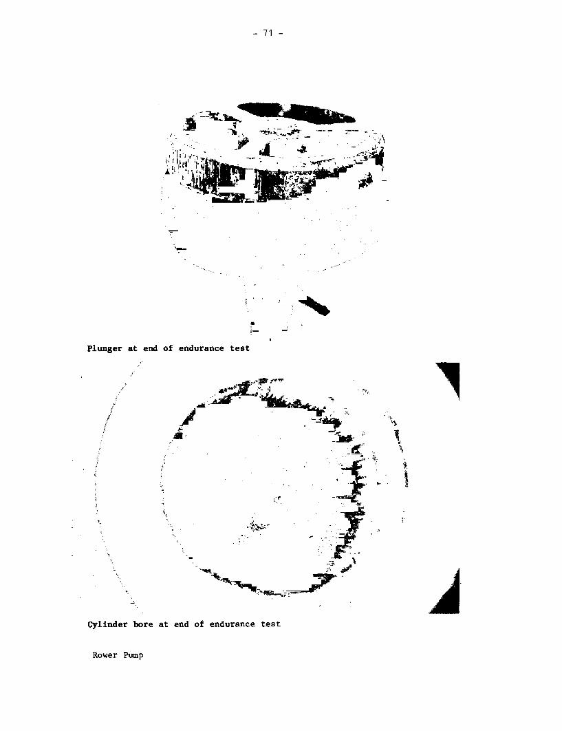
- 71 -
s - s M. -
~~ '~~~~- ~
Ai ~ ~ i
Pylunder br at end of endurance test
Roe Pump, -

- 72 -
Volanta Pump (both types)
Ia aD
0
04.
C *. ~ I
9 . 0
.0~~~~
1/~~~~~~~~~~~~~~~~1

- 73 -
VOLANTA
1.1 Manufacturer Jansen Venneboer B.V.
Address Industrieweg 4,Postbus 12, 8130 AA WijheThe Netherlands
1.2 Description The Volanta pump is made in Holland and in UpperVolta. It uses a heavy fly wheel to generate aconventional reciprocating action but in many otherways is unconventional.
Two types of cylinder were supplied; these arereferred to hereafter as cylinder types 1 and 2.Type 1 had a machined nylon cylinder body and astainless steel plunger, with a turned bronzesealing ring. Type 2 had a glass reinforcedplastic cylinder body and a long, close-fittingstainless steel plunger, with no other seal.
Connection between the above- and below-groundparts was by cable in the samples supplied fortesting, though the manufacturer now suppliessteel rods. The complete cylinder is designed tobe extractable from the well, using the connectingcable or rods, without the need to remove the uPVCrising main.
Above ground the pumpstand is unusually large.For testing, the pumps were supplied withsupporting steel framework, but in fieldinstallations the crankshaft would be supported bya concrete pillar as shown, or by a fabricatedsteel box. The pump stroke is adjustable tocompensate for operating depth.
1.3 Price $845 ex worksComplete for 20 m depth, lots of 50.
2. INSPECTION
2.1 Packaging The pumps were packed in one wooden case and threereinforced cardboard boxes, plus one bundle ofpipes. The wooden case contained two pumpstands.Two of the boxes contained components for two pumpsand the other box contained spare parts. The fly-wheels were bound together but not packaged.
Volanta

- 74 -
Although the wooden case was satisfactory, thecardboard boxes were unsuitable for the amount ofweight put in them, and the components were looseinside. Several components were broken or
damaged. The packaging of the pipes wascompletely unsuitable, four of the six pipesbundled together were damaged in transit.
4'~~~~~~4
7~~~~~~'-
b-~~~ ,1,.r --;
'I -,---lj k '
Inadequate Packaging in Cardboard Boxes
Volanta

- 75 -
Broken Pipes
k
EJ'~~~- ad
2.2 Condition as The centre bolts were missing from the pumpstandReceived cross braces. One crank arm was bent in transit.
One handle was bent. The standard of welding waspoor on the flanges of the T-pieces of bothsamples. The galvanising was poor inside the spoutunits. Plastic parts of some pipe fittings werebroken in transit and the ends on some pipesections were also damaged.
2.3 Installation and Installation and maintenance information was notMaintenance supplied with the pumps, but a useful brochure andInformation engineering drawings were provided under separate
cover.
Volanta

- 76 -
3. WEIGHTS & MEASURES
3.1 Weights Pump stand 76.5 kgCylinder type 1: 9.4 kgCylinder type 2: 10.0 kgDrop Pipe (per m): 1.7 kg
3.2 Dimensions Nominal cylinder bore (both types): 50 mmDrop pipe size: 3.0 inchOutside diameter of below-groundassembly: 101 mm
The pump stroke, and therefore the nominal volume
per stroke, are variable depending on depth. (See 5.1)
3.3 Cylinder The plungers in both types of cylinder assembly were
measured: no significant taper or ovality was foundin any of the samples.
Cylinder Type 1
In the type 1 cylinder, the maximum diametrical clearance between the
plunger and the seal was found to be 0.09 mm. The surface roughness average(Ra) of both the plunger and the sealing ring were measured in three places
in a direction parallel to the cylinder axis.
The results are shown below:
SAMPLE ROUGHNESS AVERAGE (,m)
PLUNGER SEALING RING
TEST 1 TEST 2 TEST 3 MEAN TEST 1 TEST 2 TEST 3 MEAN
1 0.25 0.27 0.24 0.25 1.4 1.5 1.2 1.4
2 0.30 0.30 0.26 0.28 0.6 0.9 0.7 0.7
Measured at 0.25mm cut-off
Volanta

- 77 -
Cylinder Type 2
The bore was measured at 5 points on two mutually perpendicular axes: nosignificant taper or ovality was found in either sample.
In the type 2 cylinder, the maximum diametrical clearance between theplunger and the cylinder bore was found to be 0.29 mm, and the average was0.20mm for one sample and 0.25 mm for the other. The surface roughnessaverage (Ra) of both the plunger and the cylinder bore were measured inthree places in a direction parallel to the cylinder axis.
The results are shown below:
SAMPLE ROUGHNESS AVERAGE (Aim)
PLUNGER CYLINDER BORE
TEST 1 TEST 2 TEST 3 MEAN TEST 1 TEST 2 TEST 3 MEAN
1 0.70 0.72 0.70 0.71 0.70 0.75 0.80 0.75
2 0.14 0.17 0.17 0.16 0.50 0.70 0.50 0.57
Measured at 0.25mm cut-off
3.4 Ergonomic Measurements
Both pumps were installed using fabricated steel stands supplied by themanufacturer; in field applications, these would be replaced by concreteplinths constructed on-site, or a box stand fabricated from steel sheet.
The crankshaft requires a supporting structure 1.3 metres high, and aplatform 150 mm high is desirable for users to stand on when operating thepump.
HANDLE HEIGHT ANGULAR HANDLE VELOCITY HEIGHTMOVEMENT LENGTH RATIO OF OF
MAX MIN OF HANDLE (mm) HANDLE SPOUT(mm) (mm) (degrees) (mm)
1385 875 360 255 (1) 400
(1) Variable according to operating depth - See 5.1
Volanta

- 78 -
4. ENGINEERING ASSESSMENT
4.1 Materials of Construction
Above Ground Assembly
COMPONENT MATERIAL(S)
Crankshaft Steel
Crankshaft Bearings Standard self-aligning plummer blocks
Flywheel and Handle Steel
Connecting Rod Steel tube with standard self-aligning ball
races at each endSpout Steel tube, hot dip galvanised
Cable Steel, contra-wound to resist twisting
Crosshead Assembly Stainless steel shaft, steel fittings, with
PA 10 nylon guide ring
Cylinder Type 1
COMPONENT MATERIAL(S)
Cylinder Body PA 10 nylon
Plunger Stainless steel
Sealing Ring BronzeFoot Valve Body Stainless steelValve Poppets Moulded rubber
Cylinder Type 2
COMPONENT MATERIAL(S)
Cylinder Body Epoxy bonded glass fibre composite
Plunger Stainless steel
Foot Valve Body Stainless steelValve Poppets Moulded rubber
Volanta

- 79 -
4.2 Manufacturing Techniques
Above-ground assembly Steel fabricationMachining of steel and plasticConcrete craft
Manufacturing the pumpstand demands basic skills in machining and steelfabrication. It may be suitable for manufacture in some developingcountries.
Cylinder Type 1 Machining of metals and plasticRubber moulding.Welding of stainless steel
The cylinder is machined from a solid billet of nylon, the stainless steelplunger and bronze sealing ring must be machined to close tolerances andhigh standards of finish.
Cylinder Type 2 Fabrication of glass reinforced plasticsMachiningRubber moulding
The cylinder body is fabricated from epoxy resin reinforced with glassfibres. Achieving a consistent high quality in the finished component islikely to demand considerable skill and experience. The plunger must bemachined to a close tolerance and with a good standard of finish.
4.3 Ease of Installation, Maintenance and Repair
4.3.1 Ease of Installation
The most time-consuming installation job is likely to be constructing theconcrete plinth. In other respects installation is straightforward andwill not require lifting tackle. It is necessary to adjust the pump strokeand the length of the connecting rod to suit the depth of water in thewell.
Volanta

- 80 -
4.3.2 Ease of Pumpstand Maintenance and Repair
The most frequent maintenance operation is likely to be tightening the gland
at the top of the connecting rod, but this is a very simple task. Indeed
all pumpstand maintenance should be straight forward, requiring only a few
spanners and simple hand tools.
4.3.3 Ease of Below-ground Maintenance and Repair
Both types of cylinder are designed to be extracted from the well on the end
of the connecting assembly without the need to remove the rising main. Our
experience suggests that the rods which the manufacturer now supplies are
likely to be more reliable than cables.
4.4 Resistance to Contamination and Abuse
4.4.1 Resistance to Contamination
The spout may be contaminated by domestic animals but in other respects
contamination is unlikely.
4.4.2 Likely Resistance to Abuse
The pump is generally robust but many fixings have been designed to be easy
to remove without the need for tools. This may be a disadvantage in some
countries.
4.5 Potential Safety Hazards
The rotating flywheel has a great deal of inertia and is therefore
potentially hazardous particularly to children. The rotating crank arm
could be dangerous also.
Volanta

- 81 -
4.6 Suggested Design Improvements
Above Ground Assembly
The crank arm should be replaced by a disc, for safety.
The flywheel would be safer to use if:
it were a smooth disc rather than spoked;if it were lighter, and therefore had less inertia.
The flywheel would be easier to use if the handle was 100 mm longer.
It is difficult to reconcile these conflicting requirements of safety andease of operation in a flywheel-operated handpump.
Cylinder Type 1
NOTE: Notification was given on 23 May 1983 that the type 1 cylinderwas now discontinued but it was agreed that it should be kept in thetest to provide useful comparative information.
The cylinder body, which appears to be turned from a solid billet of material,could be replaced by a length of a suitable standard plastic pipe.
The method of attaching the upper cap, using small setscrews, may not bestrong enough to resist the force needed to extract the cylinder.
Cylinder Type 2
The method of attachment of the cable imposes a high point load, which islikely to cause premature failure of the cable.
The valves might be more efficient if their lift were reduced, ideally to onequarter of the effective diameter, provided that this will allow the valvemouldings to be inserted and extracted.
NOTE: This cylinder was modified by the manufacturer on the 23 May, 1983.The taper seat is now at the top of the cylinder to alleviate problemsof sediment building up between the cylinder body and the rising main.The valve lift was reduced, and weights added to the valve poppets.
Connecting Assembly
The manufacturer now supplies rods, with hook and eye connections, ratherthan cable.
Volanta

- 82 -
5. PUMP PERFORMANCE
5.1 Volume Flow, Work Input and Efficiency
The description of the method can be found in the Test Procedure.
Examples of performance graphs are given in Appendix II.
Rotating crank armshowing positionsable to be selectedfor operation atdifferent waterdepths.
The manufacturer's recommendations for the crank position were as
follows:
Position 1 2 3 4 5 6
Depth (m) < 15 15 - 21 21 - 30 30 - 40 40 - 55 55 - 80
Crank throw (mm) 310 240 190 150 120 100
Position selected 7m Users 25m 45m
for test
Volanta

- 83 -
Cylinder Type 1
HEAD 7m 25m 45m
Pumping Rate(revs/min) 18 24 26 34 19 27 35 21 27 33 37
Vol/revs (litres) 0.61 0.61 0.60 0.58 0.33 0.33 0.33 0.23 0.25 0.25 0.25
Work input/rev(J) 140 119 99 92 140 132 136 157 156 181 181
Efficiency (%) 29 35 41 43 57 61 59 65 69 60 60
Cylinder Type 2
HEAD 7m 25m 45m
Pumping Rate(revs/min) 23 31 37 22 29 37 20 28 36
Vol/rev (litres) 0.61 0.61 0.61 0.32 0.33 0.34 0.24 0.25 0.25
Work input/rev (J) 128 120 118 148 162 151 144 180 190
Efficiency (%) 32 34 35 53 49 54 73 59 58
NOTE: It was difficult to accelerate the flywheel and sustain the targetoperating speed within the nine revolution limit of thepotentiometer. See the manufacturers comments in the verdict.
Volanta

- 84 -
5.2 Leakage Tests
Cylinder Type 1
No leakage was observed from the foot valve, but some leakage was noted around
the cylinder taper seat as follows
Head Volume Leakage Rate
(m) (ml/5 minutes) (ml/minute)
7 6 1.225 21 4.245 35 7.0
The excessive leakage was probably due to dimensional inconsistencies.
Cylinder Type 2
Head Volume Leakage Rate
(m) (ml/5 minutes) (ml/minute)
7 1.5 0.3
25 3.0 0.645 3.0 0.6
6. USER TRIAL
6.1 User Responses
Details of the organisation of this trial can be found in the Test Procedure.
6.2 Observations
Several small children could not cope with the high starting efforts and
never succeeded in completing one revolution; they filled the bucket by
"rocking" the flywheel. Some children preferred to turn the wheel by
pulling on successive spokes with alternate hands, "climbing" round the
wheel, rather than using the handle. Many users found the handle too short
and tended to catch their elbows on the spokes when first operating the pump.
Following consultation with the manufacturer, a further user trial was carried
out, using a 150 mm plinth on which users could stand when operating the pump.
Smaller users found that the plinth offered some advantage, but nevertheless had
difficulty in maintaining sufficient force on the handle throughout its
movement to establish a smooth rhythmn.
Only one user, an adult woman, achieved an operating speed greater than 50
revs/min. All the users criticised the handle as being too short. Several
users tended to catch their elbows on the spokes of the flywheel.
Volanta
- 85 -
7. ENDURANCE
A detailed description of the endurance test method can be found in the TestProcedure.
General Comments
The cable originally supplied broke several times in the early stages of theendurance test. The type 2 cylinder was replaced by the second sample after24 hours because debris from a broken cable had dropped into the cylindercausing a deep score in the bore. Springs were introduced into the cable torepresent the inherent elasticity of 45 m of cable - the actual cable lengthin the test installation was less than 5 m - but these fatigued very rapidly.The manufacturer supplied thicker cable of galvanised steel rather thanstainless steel, and this was used to replace the original cable as necessarywhen the latter broke.
Because the stresses in the short cable used for this test were not consideredto be entirely representative of conditions in the field, cable breakages havenot been highlighted as pump failures. However, failures of componentsrelated to the cable, but not the cable itself, are noted.
For performance testing the length of the above-ground connecting rod wasadjusted to the 7 m depth setting. This enabled the pump stroke to be adjustedfor operation at 7, 25 or 45 m. This caused premature wear in the wellheadgland, and for the endurance test it was necessary to adjust the connecting rodfor the stroke specified for 45 m.
The upper cable fixing point broke in both pump types, and at the lowerfixing point several cable thimbles broke up as a result of localisedstress. On one occasion, debris from a broken thimble dropped into the type2 cylinder causing the plunger to seize in the bore. Conventional steelthimbles were replaced by turned acetal pulleys and the method of attachmentwas modified to improve the distribution of stress. The modified componentswere still in good condition at the end of the test.
At the 3000 hour inspection, the type 2 cylinder could not be extracted fromthe taper seat in the rising main. Kieselguhr, which was added to the waterfor the third 1000 hour stage, had accumulated between the cylinder body andthe rising main, and the cylinder was 'sand locked'. It was released byremoving the lower section of rising main, but in the field this would entailremoval of the complete below-ground assembly.
Leaking joints in the rising main for the type 2 cylinder could not becured by conventional pipe sealing compounds. However, worm-drive hoseclips applied around the outside of the joints ensured an adequate seal.
Volanta

- 86 -
Breakdown Incidence
Breakdowns are shown in bold type.
Cylinder Type 1
Hours 1027 2094 3125 4164
0 2R I 3451 3699
Isptnspect Iion I
& full per- Inspecticn & Inspection & volume flow Inspection
formance test volun flow & volue flow & fullI I ( l Ahlp top performance
ahle top C| be ddidtle fixing test
f1xhr point brdka at pD1ntb iec m bottoa broka
Cabe tle Cab thilbmrken at br1ka at bothbottom cmerti bop and botton
replaced by tuameacetal paURys
Cylinlder Type 2
Hburs 1027 2094 3125 4164
0 i 1 2931 1 3214 3410 1
Ispection nspection & Inspection & Inspection & | | Inspection &
& full volue flow volume flow voltne flow full per-
performance I I formannce test
test clame top |s Tnfxing point I in risi mnnin
Cylinder 'smat- fmrn hunlockd' in rlsirg bn*m thintlemain mn bottom axcetiamCabl tinslp cemo pller tobroke at bottom seize - tihiile
eti raced by turned
Volanta

- 87 -
Details of the Endurance Test
Breakdowns are shown in bold type.
Cylinder Type 1
HOURS
1027 Inspection after first 1000 hour stage
(a) Some scratching of guide rod where it passed through the gland(b) Plunger polished on the working area(c) Light scale deposit on plunger and cable, but no corrosion
2054 Cable top fixing point broken - the steel loop on the undersideof the guide plunger had broken at the point of attachment of thecable - the guide plunger was replaced by the component from thesecond sample
Estimated amount of water pumped to breakdown .... ......... 1.0 million litres
2094 Inspection after second 1000 hour stage
,a) Further polishing of plunger(b) Self aligning bushes loose in ends of connecting rod(c) No significant corrosion
2828 Cable thimble broken at connection with plunger - replaced
Estimated additional amount of water pumped to breakdown... 0.4 million litres
3125 Inspection after third 1000 hour stage
(a) Self-aligning bushes in connecting rod still loose, but noworse than at 2000 hour inspection
(b) Filter no longer attached to base of cylinder(c) Further polishing of plunger(d) No significant corrosion(e) Cable thimble broken at connection with plunger - replaced
Estimated additional amount of water pumped to breakdown ... 0.1 million litres
3451 Cable thimbles broken at both top and bottom cable connections -replaced by turned acetal pulleys
Estimated additional amount of water pumped to breakdown ... 0.2 million litres
3699 Cable top fixing point broken - the steel loop on the undersideof the guide plunger had broken at the point of attachment of thecable - the steel loop was replaced and re-shaped to improve thedistribution of stress
Estimated additional amount of water pumped to breakdown ... 0.1 million litres
Volanta

- 88 -
4164 Final Inspection
1. Cylinder Plunger and seal scratched on one side but otherwise no
perceptable wear
2. Valves Some wear on plunger and foot valves, but otherwise ingood condition and still serviceable
3. Pumpstand (a) Connecting rod bearings remain loose but still serviceable(b) Well head gland leaking slightly when pump stationary but
satisfactory when operating pump
4. Filter Thickly coated with sand and general debris but
still working
5. Corrosion No significant corrosion
Estimated total amount of water pumped in 4000 hours ..... 1.8 million litres
Cylinder Type 2
HOURS
1027 Inspection after first 1000 hour stage
(a) Some scratching of guide rod where it passed through the gland
(b) Light scale deposit on plunger and cable, but no corrosion
2094 Inspection after second 1000 hour stage
(a) Slight scratches on plunger(b) Flywheel loose on spindle - tightened(c) No significant corrosion
2931 Cable top fixing point broken - the steel loop on the undersideof the guide had broken at the point of attachment of the cable- the loop was replaced
Estimated amount of water pumped to breakdown ........ 1.5 million litres
3125 Inspection after third 1000 hour stage
(a) Cylinder 'sand-locked' in rising main - Kieselguhrhad accumulated between the cylinder body and the risingmaIn - the cylinder could not be released without removingthe bottom section of rising main
(b) Cable thimble broken at connection with plunger(c) Filter liberally coated with Kieselguhr but still
working - cleaned(d) Plunger polished on working areas(e) Some rust on cylinder end cap
Estimated additional amount of water pumped to breakdown ... 0.1 million litres
Volanta

- 89 -
HOURS
3214 Leaking joints in rising main - corrected by applying worm-drivehose clips around outside of joints.
Estimated additional amount of water pumped to breakdown .. <0.1 million litres
3410 Plunger seized - debris from a broken thimble on the bottomcable connection had fallen into the cylinder and jammed theplunger. The plunger was released and the steel thimblewas replaced by a turned acetal pulley.
Estimated additional amount of water pumped to breakdown ... 0.1 million litres
4164 FINAL INSPECTION
1. Cylinder (a) Cylinder bore pitted, even in the unswept areas(b) Plunger scratched, but otherwise no perceptable wear
2. Valves Some wear on plunger and foot valves, but otherwisein good condition and still serviceable
3. Pumpstand Well head gland leaking slightly when pump stationarybut satisfactory when operating pump
4. Filter Thickly coated with sand and general debris butstill working
5. Corrosion Some rust on cylinder end cap
Estimated total amount of water pumped in 4000 hours ... 1.9 million litres
Cylinder Type 1Leakage Tests
Volume Flow Tests at 45 m (litres) at 7 m (ml/min)
Revs/min 20 30 40
New 0.23 0.25 0.25 1.2After 1000 hours 0.15 0.14 0.15 0.3After 2000 hours - 0.22 0.23 0.7After 3000 hours 0.19 0.19 0.21 0.3After 4000 hours - 0.13 0.13 0.2
*NOTE: Springs were fitted between 0 and 1000 hours, to simulate thestretch in 45 m cable - after several breakages, these were removedbetween 1000 and 2000 hours, with resultant improvements in volumedelivered per stroke.
Volanta

- 90 -
Cylinder Type 2
Leakage TestsVolume Flow Tests at 45 m (litres) at 7 m (ml/min)
Revs/min 20 30 40
New 0.24 0.25 0.25 0.3
After 1000 hours 0.12 0.15 0.16 < 0.1
After 2000 hours - 0.22 0.22 0.6
After 3000 hours 0.20 0.20 0.23 0.5
After 4000 hours - 0.14 0.14 0.3
*NOTE: Springs were fitted between 0 and 1000 hours, to simulate the
stretch in 45 m cable - after several breakages, these were removed
between 1000 and 2000 hours, with resultant improvements in volume
delivered per stroke.
Pump Performance After Endurance Testing
Cylinder Type 1
HEAD 7m 25m 45m
Pumping Rate(revs/min) 31 39 47 31 38 45 30 40 46
Vol/rev (litres) 0.54 0.54 0.53 0.28 0.28 0.29 0.13 0.13 0.14
Work input/rev(J) 100 112 121 119 147 132 112 119 144
Efficiency (%) 36 32 29 56 46 53 49 46 42
Cylinder Type 2
HEAD 7m 25m 45m
Pumping Rate(revs/min) 29 37 47 27 35 39 42 29 40 46
Vol/revs (litres) 0.57 0.53 0.50 0.28 0.29 0.32 0.31 0.14 0.14 0.16
Work input/rev (J) 138 144 162 158 170 194 177 129 121 153
Efficiency (%) 28 24 21 42 41 40 43 47 52 46
Volanta

- 91 -
8. ABUSE TESTS
8.1 Side Impact Tests
Body test not applicable - tested by impact on spokes of wheel - spokesbent at an impact of 400 Joules but pump still usable.
8.2 Handle Shock Test
Not applicable.
9. VERDICT
The Volanta pump with the two types of cylinder as supplied for this testproved to be unreliable in use.
Users found the pump difficult to start and maintain a steady rhythm. Inthe field with more time available there will be an opportunity for users todevelop a better technique. Nevertheless it is recommended thatconsideration be given to a simpler pumpstand using a conventional lever armat a considerable cost saving.
Many problems were encountered with the method of fixing the cables and somemonths after starting this test programme the manufacturer decided todiscontinue the type 1 cylinder assembly.
The pump has now been substantially modified in response to the results ofthese laboratory tests and to information from the field. Steel rods withhook-and-eye connections are now used in place of cable.
The type 1 cylinder is no longer in production and it is interesting to notethat in the tests it performed generally better than the type 2 cylinder.
If the modifications prove to be successful in future tests, then theVolanta may be suitable for community water supply in developing countries.It also has considerable potential for local manufacture providing adequateskills and quality control can be maintained for the cylinder assembly.
N.B.In view of the modifications made to this pump the manufacturer has askedfor the latest design to be reassessed. He has also asked for this work toinclude comparison of the performance of the pump on the 50 m borehole aswell as in the tower, using a 'flying start' technique for the performancetests. The manufacturer considers that the performance of his pump in thetower may not be representative of results obtained in the field where ithas become apparent that the pump works best at speeds of around 55 rpm.
Volanta

- 92 -
Korat Pump
t -I=~
_____ *~~~~~~~~~~~~~, -

- 93 -
KORAT 608 A-i
1.1 Manufacturer Saha Kolkarn Factory
Address 94-96 Soi Sukapiban 2,Ramintra,Bangkhen,BANGKOK,Thailand.
1.2 Description The Korat 608 A-1 is a deep-well force pump, made inThailand. The pumpstand is mainly cast iron with a rackand quadrant mechanism and a wooden handle. It must bemounted on a plinth at least as tall as the largestcontainer to be used. The cylinder is seamless brasstube, and the plunger has two conventional leather cupseals. There are two foot valves, one in the base ofthe cylinder, the other at the end of a short dip tubebelow.
1.3 Price in 1982 $295, supplied complete for 20 metres depth.
2. INSPECTION
2.1 Packaging The pumps were delivered in two wooden packing cases,one containing the pumpstands, the other the handles,pipes and pump rods.
The case containing the pumpstands had been damaged andthe grease cups on the handle castings of both pumpswere broken.
2.2 Condition as Both samples were in working order as received in spiteReceived of minor defects (see Table). Such defects would be
likely to cause premature failure of the pump if notremedied before installation.
COMPONENT or FEATURE NO. of SAMPLES DEFECTSAFFECTED
Grease cups 2 BrokenCylinder end caps 7 (8 supplied) Porous castingsUpper connecting rod nut 1 Misaligned threadLower rack roller 1 Seized - not rotatingHandle 1 Small split along half its
length starting from holesFoot valve 1 Rubber washer squeezed out
of jointVarious 2 Minor surface corrosion on
unprotected ferroussurfaces
Korat Pump

- 94 -
2.3 Installation & Maintenance Information None supplied with pump.
3. WEIGHTS & MEASURES
3.1 Weights Pumpstand 47 kgCylinder assembly 5.5 kgPump rods 1.1 kg per metre
3.2 Dimensions Nominal cylinder bore: 76 mmActual pump stroke: 80 mmNominal volume per stroke: 363 mlDrop pipe size: 1.50 inchesOutside diameter of below-ground assembly: 90 mmPump rod diameter: 0.5 inchesMaximum usable cylinderlength: 255 mm
3.3 Cylinder Bore No significant taper or ovality was found in either of thesamples.
The surface roughness average (Ra) was measured in threeplaces in a direction parallel to the cylinder axis.
SAMPLE CYLINDER BORE ROUGHNESS AVERAGE (pm)TEST 1 TEST 2 TEST 3 MEAN
1 Extruded brass 0.05 0.05 0.07 0.06
2 Extruded brass 0.08 0.07 0.08 0.08
Measured at 0.25 mm cut-off
3.4 Ergonomic Measurements
The pump must be mounted on a plinth to provide clearance under thespout. A plinth of 500 mm height was chosen to present the handle at asuitable height for operation while providing adequate room below thespout for typical containers.
HANDLE HEIGHT PLATFORM ANGULAR HANDLE VELOCITY HEIGHTHEIGHT MOVEMENT LENGTH RATIO OF OF SPOUT
MAX( 1 ) MINM1 ) (mm) OF HANDLE (mm) HANDLE (mm)(mm) (mm) (degrees)
1365 485 500 50 1055 10.8:1 490
(1) Measured without compressing bump stops.
Korat Pump
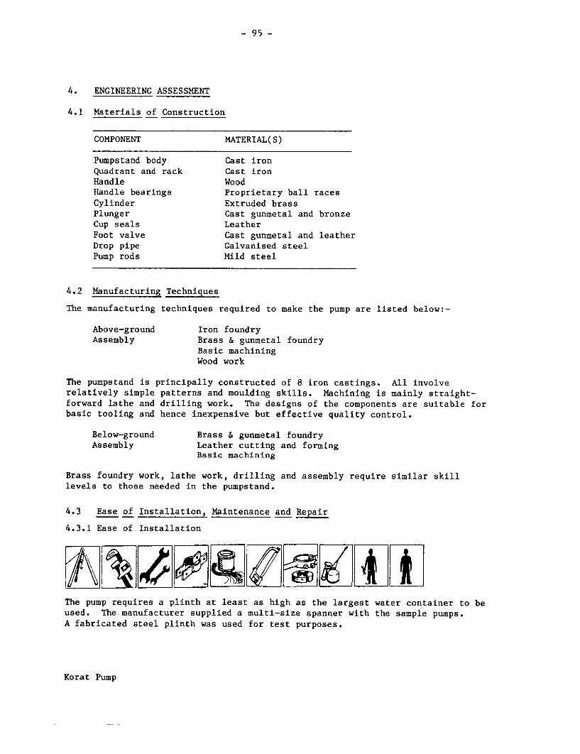
- 95 -
4. ENGINEERING ASSESSMENT
4.1 Materials of Construction
COMPONENT MATERIAL(S)
Pumpstand body Cast ironQuadrant and rack Cast ironHandle WoodHandle bearings Proprietary ball racesCylinder Extruded brassPlunger Cast gunmetal and bronzeCup seals LeatherFoot valve Cast gunmetal and leatherDrop pipe Galvanised steelPump rods Mild steel
4.2 Manufacturing Techniques
The manufacturing techniques required to make the pump are listed below:-
Above-ground Iron foundryAssembly Brass & gunmetal foundry
Basic machiningWood work
The pumpstand is principally constructed of 8 iron castings. All involverelatively simple patterns and moulding skills. Machining is mainly straight-forward lathe and drilling work. The designs of the components are suitable forbasic tooling and hence inexpensive but effective quality control.
Below-ground Brass & gunmetal foundryAssembly Leather cutting and forming
Basic machining
Brass foundry work, lathe work, drilling and assembly require similar skilllevels to those needed in the pumpstand.
4.3 Ease of Installation, Maintenance and Repair
4.3.1 Ease of Installation
The pump requires a plinth at least as high as the largest water container to beused. The manufacturer supplied a multi-size spanner with the sample pumps.A fabricated steel plinth was used for test purposes.
Korat Pump

- 96 -
4.3.2 Ease of Pumpstand Maintenance and Repair
Regular lubrication is required. The most frequent repairs are likely to be to
the quadrant and rack although this should not be in less than 2 years; the
handle bearings are likely to outlive the gear teeth. The pumpstand is easy to
dismantle, and removal from the wellhead is not required. A broken handle couldbe replaced using indigenous materials, otherwise manufacturer's spares will be
required.
4.3.3 Ease of Below-ground Maintenance & Repair
To allow the below-ground assembly to be extracted from the borehole, thepumpstand must first be partially dismantled. This is a relatively simple task;
two people could manhandle the pumpstand to remove it from the plinth.
The rising main and rodding must then be extracted length-by-length until the
cylinder is brought to the surface. Lifting tackle would be required to copewith the weight of the below-ground assembly.
4.4 Resistance to Contamination and Abuse
4.4.1 Resistance to Contamination
The pumpstand is adequately sealed against contamination, provided care is taken
to seal the base of the pumpstand to the wellhead.
4.4.2 Likely Resistance to Abuse
The pumpstand is generally robust, but there are many easily-removed nuts andbolts. The handle would be easy to replace.
4.5 Potential Safety Hazards
The pumpstand is hard and angular, withmany exposed fastenings offeringpotentially hazardous sharp edges.
The quadrant and rack present apotentially dangerous finger trap, iparticularly in view of the largemechanical advantage of the handle. ASee photograph, right.
Korat Pump

- 97 -
4.6 Suggested Design Improvements
The plunger valve lift should be reduced, ideally to one quarter of itseffective diameter, and its lateral location improved.
The grease cup lubricators are a good idea in principle, but more robustcomponents are needed.
The quadrant and rack present a safetyhazard and should be shrouded. Thismay be achieved by modifying the zcasting patterns for the pumpstandside plates as shown, right.
In response, the manufacturer hasmodified the pumpstand by adding acover plate shielding the quadrantfrom above, and by reducing the liftof the plunger valve. The cover plateprovides a good deal of protection butcan easily be removed and left off.The suggested change to the casting istherefore preferable.
5. PUMP PERFORMANCE
5.1 Volume Flow, Work Input and Efficiency
The description of the method can be found in the Test Procedure.
HEAD 7 m 25 m 45 m
Nominal PumpingRate (strokes/min) 30 40 50 30 40 50 30 40 50
Vol/stroke (litres) 0.39 0.40 0.40 0.36 0.35 0.35 0.34 0.35 0.36
Work input/stroke (J) 57 50 54 175 159 152 218 200 196
Efficiency (%) 46 53 50 50 53 56 68 76 80
Korat Pump

- 98 -
5.2 Leakage Tests
The leakage through the pump was assessed by first operating the pump to ensure
that it was fully charged and then draining the water in the tank. The amount
of water leaking past the foot valve in 10 minutes was then measured.
HEAD 7 m 25 m 45 m
Leakage rate Not significant 1.7 4.4
(ml/minute) (less than 0.1 ml/min)
This pump was found to be leaking from the cylinder end caps. On investigation
the castings were found to be porous . All spare castings were checked and all
found to be defective. The original castings were therefore filled with shellac
for the remaining performance and endurance tests. In subsequent tests of the
leakage of the end caps was found to be not significant.
6. USER TRIAL
6.1 User Responses
Details of the organisation of this trial can be found in the Test
Procedure, and the statistical analysis of user responses is presented in
Appendix I.
6.2 Observations
Many users complained that the handle of this pump was too high, but this was
not the only problem. The handle is long but the stroke is relatively short,
with a predominantly vertical movement. Users found it difficult to bring
several muscle groups into play since most of the effort had to be supplied by
arms and shoulders only.
7. ENDURANCE
A detailed description of the endurance test method can be found in the Test
Procedure.
General Comments
The pump was tested at 40 strokes per minute at a simulated head of 45 metres.
4000 hours of endurance testing completely wore out the quadrant. The rack
teeth were also worn, but could be reversed top to bottom and used for a while
longer with a new quadrant.Both rack guide rollers seized towards the end of endurance test programme. In
the short term this would increase the friction in the pumphead and make the
pump slightly harder to operate. In the long term it would generate localised
wear on the rollers which would accelerate the wear on the rack and quadrant
teeth.The cylinder was generally in good condition after 4000 hours, with no
significant wear. The leather cup seals and valves showed signs of wear, but
still worked satisfactorily.
Korat Pump

- 99 -
Breakdown Incidence
Breakdowns are shown in bold type.
Hours: 1072 2044 30603595 4029
Quadrant Handleand Rack QuadrantSeized and Rack
I I | Worn OutInspection Inspection Inspection Inspection Inspectionand full and volume and volume and volume and fullperformance flow flow flow performancetest test
Details of the Endurance Test
Breakdowns are shown in bold type.
HOURS
651 Swarf collecting on top of pump from worn rack and quadrant
1072 INSPECTION after 1st 1000 hours:
(a) Nut adrift from upper foot valve, lodged in lower valve(b) Some deterioration of rubber seating of lower foot valve(c) Plunger valve head worn(d) Plenty of swarf on pump top from worn rack and quadrant(e) Some corrosion of ferrous parts(f) Gland nut loose - retightened
2044 INSPECTION after 2nd 1000 hours:
(a) Plunger valve continuing to wear(b) Rubber seat on lower foot valve noticeably worn(c) More swarf on pump top(d) Handle loose in socket(e) Noticeable corrosion of ferrous parts
3060 INSPECTION after 3rd 1000 hours:
(a) Plunger valve continuing to wear(b) Quadrant teeth noticeably worn though still serviceable(c) Handle loose in socket(d) Noticeable corrosion of ferrous parts though still serviceable
Korat Pump

- 100 -
HOURS
3595 Bush in top cover adrift, quadrant and rack out of mesh so pump would
not operate. Bush replaced, test continued with original rack and
quadrant.
Estimated Amount of water pumped to breakdown ........ 3.1 million litres
3934 Upper guide roller seized though pump still working - no action
4029 Quadrant and rack locked due to wear in gear teeth and seized guide
roller - test terminated.
Estimated additional amount of water pumped to breakdown ...... 0.4 million litres
4029 FINAL INSPECTION
1. Pumpstand (a) Quadrant teeth almost entirely worn away - rackteeth also worn but could be upended and used for a
while with a new quadrant(b) Both guide rollers behind rack seized on their
shafts(c) Upper guide rod had "picked up" on its bush
2. Cylinder Slight scratching of cylinder bore but no significant wear
3. Plunger (a) Plunger valve noticeably worn on its diameter but
still working(b) Some scratches on both cup leathers, and one
distorted, but still serviceable(c) Small amounts of sand lodged behind both cup leathers
4. Foot Valves (a) Leather sealing washer in cylinder foot valve has
compressed, allowing metal-to-metal contact between
valve and seat(b) Split rubber seal in dip tube foot valve
5. Corrosion Noticeable corrosion of all ferrous parts, particularly
lock nut between connecting rod and plunger, and dip tube
valve body.
Estimated total amount of water pumped in 4000 hours ...... 3.5 million litres.
Korat Pump
- 101 -
Leakage TestsVolume Flow Tests at 45m (litres) at 7 m (ml/min)
Strokes/min 30 40 50
New 0.34 0.35 0.36 less than 0.1*After 1000 hours 0.39 0.39 0.40 0.2After 2000 hours 0.37 0.37 0.38 less than 0.1After 3000 hours 0.37 0.38 0.39 less than 0.1After 4000 hours 0.35 0.35 0.36 4.8
* After sealing cylinder end caps with shellac
Pump Performance after Endurance
HEAD 7 m 25 m 45 m
Nominal PumpingRate (str/min) 30 40 50 30 40 50 30 40 50
Vol/stroke (litres) 0.38 0.38 0.40 0.38 0.38 0.39 0.35 0.35 0.36
Work input/stroke (J) 56 55 55 143 131 148 219 253 251
Efficiency (%) 46 47 49 65 71 63 70 61 63
If compared with the original performance data these tests show animprovement in volume flow, and therefore in efficiency at 25 m depth. Thissuggests that bedding-in the cup leathers has improved the seal, but thewear of the quadrant mechanism has increased friction.
8. ABUSE TESTS
8.1 Side Impact Tests
The Korat was undamaged in the side impact tests on both body and handle.
8.2 Handle Shock Tests
In this test the pump completed its allotted 96,000 cycles withoutfailure.
9. VERDICT
A robust pump potentially suitable for community water supply. The rack andquadrant will wear in time but they can be easily replaced. It might bebetter to consider an India Mk II approach eliminating the rack andsimplifying the quadrant. Easy to maintain or repair above-ground, difficultbelow-ground, though cylinder assembly robust and reliable. Potentiallydangerous moving parts should be permanently shrouded. Moderately priced.
Korat Pump

dwnd Uo5eJt
- ZOI -

- 103 -
DRAGON
1.1 Manufacturer Kawamoto Pump Mfg. Co. Limited,
Address 11-39 4-Chome, Ohsu,Naka-Ku,NAGOYA, Japan.
1.2 Description The Dragon pump, made in Japan, can be suppliedeither as a shallow-well suction pump or as a deep-well force pump. The pump was tested in its deep-well configuration. The pumpstand is principallycast iron, with a discharge valve in the spoutallowing either free discharge or delivery underpressure through a hose or pipe. The tubular steelhandle moves through an unusually wide arc of 1780.
In the deep-well configuration, the shallow-wellcast-iron cylinder body with its enamelled steel liner,is retained as a pedestal. In addition, the pumprequires a mounting plinth at least 305 mm high, toprovide adequate clearance under the spout. Thedeep-well cylinder is conventional, seamless brasstube of 63 mm bore with cast iron end caps. Theplunger has two leather cup seals, and the foot valvehas a rubber seat.
1.2 Price in 1982 $362 supplied complete for deep-well use
2. INSPECTION
2.1 Packaging The pumps were delivered neatly and securely packed intwo corrugated cardboard cartons.
One carton contained the pumpstands with all thecomponents required for shallow-well use. The cartonwas fully lined with moulded packing for the pump headunits.
The second carton contained the additional componentsneeded for deep-well use, packed in expanded polystyrenebeads.
Both cartons were unusually easy to handle.
2.2 Condition as The pumps were received in excellent condition.Received
2.3 Installation & Maintenance Information
None supplied with the pump. Setting up was difficult because the cylinderstroke length was virtually the same as the distance through which the pumprod connection moves in the pumphead. This could possibly lead toinstallation problems in the field if no instructions are provided.
Dragon Pump

-104 -
3. WEIGHTS and MEASURES
3.1 Weights Pumpstand 19.0 kg
Cylinder assembly 5.0 kgPump rods 1.1 kg per metre
3.2 Dimensions Nominal cylinder bore: 63 mm
Actual pump stroke: 180 mm
Nominal volume per stroke: 561 ml
Drop pipe size: 1.25 inchesOutside diameter of below-ground assembly: 70 mm
Pump rod diameter: 0.5 inchesMaximum usable cylinder
length: 180 mm
3.3 Cylinder Bore No significant taper or ovality was found in either of the
samples.
The surface roughness average (Ra) was measured in three
places in a direction parallel to the cylinder axis.
SAMPLE CYLINDER BORE ROUGHNESS AVERAGE (pm)TEST 1 TEST 2 TEST 3 MEAN
1 Extruded brass 0.10 0.08 0.08 0.09
2 Extruded brass 0.10 0.12 0.13 0.12
Measured at 0.25 mm cut-off
3.4 Ergonomic Measurements The pump must be mounted on a plinth to provide adequate
clearance under the spout.
HANDLE HEIGHT PLATFORM ANGULAR HANDLE VELOCITY HEIGHT
HEIGHT MOVEMENT LENGTH RATIO OF OF SPOUT
MAX( 1 ) MINM1 ) (mm) OF HANDLE (mm) HANDLE (mm)
(mm) (mm) (degrees)
1139 95 305 178 660 7.8:1 480
(1) Measured without compressing bump stops
Dragon Pump
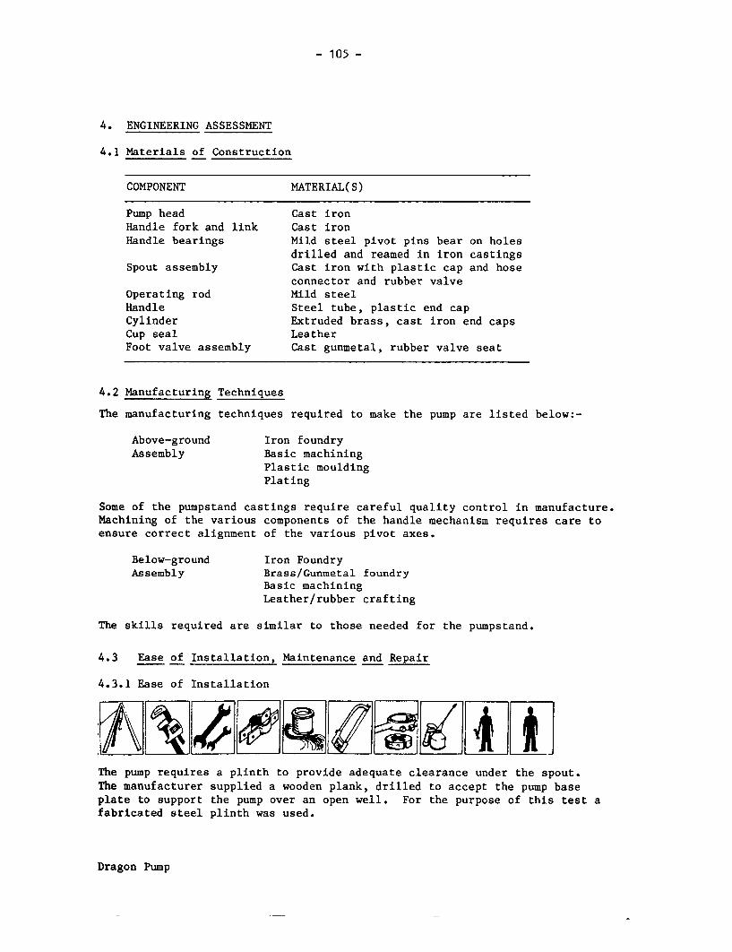
- 105 -
4. ENGINEERING ASSESSMENT
4.1 Materials of Construction
COMPONENT MATERIAL(S)
Pump head Cast ironHandle fork and link Cast ironHandle bearings Mild steel pivot pins bear on holes
drilled and reamed in iron castingsSpout assembly Cast iron with plastic cap and hose
connector and rubber valveOperating rod Mild steelHandle Steel tube, plastic end capCylinder Extruded brass, cast iron end capsCup seal LeatherFoot valve assembly Cast gunmetal, rubber valve seat
4.2 Manufacturing Techniques
The manufacturing techniques required to make the pump are listed below:-
Above-ground Iron foundryAssembly Basic machining
Plastic mouldingPlating
Some of the pumpstand castings require careful quality control in manufacture.Machining of the various components of the handle mechanism requires care toensure correct alignment of the various pivot axes.
Below-ground Iron FoundryAssembly Brass/Gunmetal foundry
Basic machiningLeather/rubber crafting
The skills required are similar to those needed for the pumpstand.
4.3 Ease of Installation, Maintenance and Repair
4.3.1 Ease of Installation
The pump requires a plinth to provide adequate clearance under the spout.The manufacturer supplied a wooden plank, drilled to accept the pump baseplate to support the pump over an open well. For the purpose of this test afabricated steel plinth was used.
Dragon Pump

- 106 -
4.3.2 Ease of Pumpstand Maintenance and Repair
The pumpstand would benefit from regular lubrication. The repairs most likely
to be required are to the handle fulcrum components, the connecting rod and the
gland nut. In all these cases, manufacturer's spares would be required. The
pumpstand is easy to dismantle, and need not be removed from the wellhead.
4.3.3 Ease of Below-ground Maintenance and Repair
Repairs require removal of the complete below-ground assembly.
4.4 Resistance to Contamination and Abuse
4.4.1 Resistance to Contamination
The top of the pump is adequately sealed, but no attempt is made to seal the
wellhead.
4.4.2 Likely Resistance to Abuse
There are many accessible fixings and components which would be easy to remove.
The cast iron fork is a potential weakness.
4.5 Potential Safety Hazards
The tubular steel handle is threaded at the outboard end to accept the moulded
plastic cap. The cap is easy to remove and could be lost. This exposes the end
of the handle, which is sharp because the burrs were not removed after cutting.
4.6 Suggested Design Improvements
The free end of the handle should not be threaded but simply belled out and
smoothed, omitting the plastic end cap.
The wishbone link may be simpler to manufacture in a developing country as two
joggled steel strips.
The handle fulcrum pinch bolt should be moved 900 to the underside, or replaced
by two circlips on the shaft, similar to those on the wishbone link pivots.
Dragon Pump

- 107 -
The height of the top housing should be reduced to:
(a) eliminate the counterbore in the gland nut,(b) eliminate unnecessary machining of the pivot casting,(c) increase the length of thread attaching the connecting rod to the
pivot casting.
The discharge valve should be removed as a cost-saving measure and only suppliedif needed. We understand that the manufacturer will now supply pumps with asimple discharge spout, if required.
All pump body flanges should be flat or increased in thickness as they areunsupported and can be broken by over-tightening the fixing bolts.
The base casting should be strengthened.
5. PUMP PERFORMANCE
5.1 Volume Flow, Work Input and Efficiency
The description of the method can be found in the Test Procedure.
HEAD 7 m 25 m 45 m
Nominal PumpingRate (strokes/min) 30 40 50 30 40 50 20 30 40
Vol/stroke (f) 0.55 0.55 0.55 0.54 0.54 0.54 0.52 0.53 0.53(litre) (p) 0.26 0.27 0.28
Work input/ (f) 122 120 128 244 252 257 340 358 366stroke (J) (p) 52 53 55
Efficiency (%) (f) 30 31 29 53 52 51 67 65 63(p) 33 34 34
(f) = Full stroke(p) = Partial stroke
The angle of the handle movement was nearly 1800 and from observation it wasanticipated that an improvement in efficiency could be obtained by usingonly the central 600 position of the handle movement. Tests conducted at 7metres confirmed a slight improvement in efficiency which may be significantat greater depths.
5.2 Leakage Tests
The measured leakage from the foot valve was not significant, i.e. less than0.1 ml/minute, at 7, 25 and 45 metre heads.
Dragon Pump

- 108 -
6. USER TRIAL
6.1 User Responses
Details of the organisation of this trial can be found in the Test
Procedure, and the statistical analysis of the user responses is presented
in Appendix I.
6.2 Observations
Many users found it difficult to decide on the best method of operation for this
pump because the angular movement of the handle is particularly large. In spite
of this, some users chose a full stroke but found the exaggerated body movements
uncomfortable.
7. ENDURANCE
A detailed description of the endurance test method can be found in the Test
Procedure.
General Comments
This pump was tested at 40 strokes per minute at a simulated head of 45 metres.
The pump failed at 2890 and 3207 hours when the pump rod broke within the thread
at the top. Components of the handle mechanism including the gland nut had to
be replaced after 2487 hours because of wear. The handle fulcrum had broken
when wear allowed it to contact the retaining bolt. At each intermediate
inspection, the spout discharge valve was found to be seized through lack of use
and was freed off.
In the final inspection, the foot valve guide was almost completely worn away,
and there was substantial wear of the valve stem. The leather cup seals and
cylinder bore were in good condition, with few signs of wear. The gland nut was
again very badly worn. The cast iron cylinder end caps and the plunger rod were
corroded, but not sufficiently to interfere to any great extent with maintenance
or performance.
Dragon Pump

-109-
Breakdown Incidence
Breakdowns are shown in bold type.
Hours: 1024 2037 3140 41472487 2890 I 3207
HandleForkBroken
Pump Rod Pp Rodl | ~~~~~Broken |Broken
Inspection Inspection Inspection Inspection Inspectionand full and volume and volume and volume and fullperformance flow flow flow performancetest test
Details of the Endurance Test
Breakdowns are shown in bold type.
HOURS
1024 INSPECTION after 1st 1000 hours:
(a) Plunger difficult to remove because of scale in bore(b) Foot valve guide worn(c) Spout would not swivel or drop into the tank-filling position(d) Some wear of pump rod gland(e) Some corrosion of cylinder end caps and plunger rod
2037 INSPECTION after 2nd 1000 hours:
(a) Handle fulcrum joints badly worn(b) More wear of foot valve guide(c) Plunger difficult to remove from cylinder(d) Signs of wear on plunger valve(e) Spout corroded and stiff as before(f) More corrosion of cylinder end caps and plunger rod
2487 Handle fork worn until it contacted fulcrum pin retaining screw and brokeas a result - new handle fork, links and pins fitted.
Estimated amount of water pumped to breakdown .............. 3.2 million litres
Dragon Pump

- 110 -
HOURS
2890 Connecting rod broken within thread at top. Gland nut and rod eye badlyworn. Connecting rod, gland nut and packing, rod eye and pivot pin allreplaced.
Estimated additional amount of water pumped to breakdown ....... 0.5 million litres
3140 INSPECTION after 3rd 1000 hours:
(a) Foot valve guide almost worn through(b) Plunger remains difficult to remove or refit(c) More corrosion on cylinder end caps and on plunger rod(d) Outlet diverter valve rusted solid
3207 Pump rod broken within thread at uppermost joint - rethreaded.
Estimated additional amount of water pumped to breakdown ....... O.4 million litres
4147 FINAL INSPECTION:
1. Pumpstand Gland worn, slight wear in handle components, butgenerally in fair condition
2. Cylinder No wear in cylinder bore though some scratches -generally in good condition
3. Plunger Generally in good condition, including cup seals
4. Foot Valve (a) Valve guide severely worn(b) Some wear on foot valve stem
5. Corrosion (a) Cylinder end caps rusty(b) Considerable rust on plunger rod(c) Outlet diverter valve rusted solid
Estimated total amount of water pumped in 4000 hours ...... 5.1 million litres.
Leakage TestsVolume Flow Tests at 45m (litres) at 7 m (ml/min)
Strokes/min 20 30 40
New 0.52 0.53 0.53 less than 0.1After 1000 hours 0.52 0.52 0.51 less than 0.1After 2000 hours 0.44 0.45 0.45 less than 0.1After 3000 hours 0.41 0.42 0.42 less than 0.1After 4000 hours 0.50 0.50 0.53 less than 0.1
Dragon Pump

Pump Performance after Endurance
HEAD 7 m 25 m 45 m
Nominal PumpingRate (strokes/min) 20 30 40 20 30 40 20 30 40
Vol/stroke (litres) (f) 0.54 0.54 0.50 0.54 0.54 0.51 0.50 0.50 0.53
Work input/stroke(J)(f) 94 94 101 207 212 215 287 291 327
Efficiency (%) (f) 39 39 33 64 62 58 77 76 70
If compared with the original performance data, these results show a generalreduction inthe work input requirement, with a consequent increase inefficiency, this suggests that bedding in of the handle pivots, has reducedfrictional losses.
8. ABUSE TESTS
8.1 Side Impact Tests
The Dragon failed the side impact test on the handle. Even at the lowestimpact energy, 50 Joules, the handle began to bend. At 200 Joules, thebase casting on the pumpstand broke. Therefore, the impact test on thebody of the pumpstand could not be carried out.
8.2 Handle Shock Test
The handle was bumped against its upper limit stop only. At the lowerlimit the handle was close to the ground, and it was considered that userswould be unlikely to bump the handle on the lower stop. The pumpcompleted its allotted 96,000 cycles without failure.
9. VERDICT
This pump appears to be designed for family use, possibly serving up to 15people. It is unlikely to be sufficiently robust for community water supply.It is inexpensive, but intensive use will produce rapid wear in the movingparts of the pumpstand, and rod breakages are also likely (see comments onpump rod constraint on page 17). It is understood that the manufacturer isworking on a new and more robust pump design for community use.
Dragon Pump

- 112 -
Moyno Pump
I
I TWSS~I
:~~ I

- 113 -
MOYNO IV 2.6
1.1 Manufacturer Robbins and Myers Inc.,
Address Moyno Pump Division,1895 Jefferson Street,Springfield,OHIO 45501, U.S.A.
1.2 Description The Moyno pump tested was made by Robbins and Myersin the U.S.A., is a positive displacement pump,which has a plated helical steel rotor within adouble-helical elastomeric stator. The pump rodsrotate instead of reciprocating up and down. Thepump is operated by a pair of rotary crank handles,driving a gearbox and one-way clutch. The pumpstandis very robust, of all-steel construction. The twinhandles make the pump suitable for operation eitherby one or two people.
1.3 Price in 1982 $550, pump only$739, supplied complete for 20 metres depth
2. INSPECTION
2.1 Packaging The pumps were packed in two cartons made from heavy-duty corrugated cardboard, approximately 12 mm thick.The carton containing the pumpstands was supported ona wooden pallet. The other carton, containing thepipes and pump rods, had wooden ends and woodeninternal reinforcements.
The cartons were strongly made and should absorb bumpsand shocks well. However, if stored or transported inwet conditions they could deteriorate.
2.2 Condition as The pumps were received in good condition. The onlyReceived minor defect was a bent foot valve strainer, which
was easily straightened.
2.3 Installation and Maintenance Information None supplied with the pump.
Moyno Pump

114 -
3. WEIGHTS and MEASURES
3.1 Weights Pumpstand 48.0 kg
Cylinder assembly 16.0 kg
Pump rods 1.2 kg. per metre
3.2 DimensionsDrop pipe size: 1.25 inches
Outside diameter of below-
ground assembly: 75 mm
Pump rod diameter: 0.5 inches
3.3 Cylinder Bore Not applicable
3.4 Ergonomic Measurements
HANDLE HEIGHT PLATFORM ANGULAR HANDLE SEPARATION HEIGHT
HEIGHT MOVEMENT LENGTH OF HANDLE OF SPOUT
MAX MIN (mm) OF HANDLE (mm) (mm) (mm)
(mm) (mm) (degrees)
1244 738 0 360 253 240 563
4. ENGINEERING ASSESSMENT
4.1 Materials of Construction
COMPONENT MATERIAL(S)
Pumpstand column Fabricated steel, galvanised
Pump top (gearbox) Cast steel
Handles Cast steel
Bearings Proprietary taper roller bearings
Gears Mild steel
Rotor Steel, hard chrome-plated
Stator Moulded elastomer in steel tube
Foot valve Gunmetal with brass strainer
Drop pipe Galvanised steel
Pump rods Galvanised steel
Moyno Pump

- 115 -
4.2 Manufacturing Techniques
The manufacturing techniques required to make the pump are listed below:-
Above-ground Iron and steel foundryAssembly Steel fabrication
Complex machining
The pumpstand demands advanced manufacturing techniques and skills. It wouldnot be suitable for manufacture in a developing country.
Below-ground Iron foundryAssembly Gunmetal foundry
Simple machiningHard chrome platingSpecialised processes (pumping element)
The pumping element demands advanced and specialised manufacturing techniquesand a high degree of skill. It would be particularly unsuitable for manufacturein a developing country.
4.3 Ease of Installation, Maintenance and Repair
4.3.1 Ease of Installation
~ *A die and diestock for threading the pump rod, together with clamps and hexagonkeys were supplied with the test samples.
4.3.2 Ease of Pumpstand Maintenance and Repair
Frequent attention to the pumpstand is unlikely to be required. A broken handlecould be replaced in the field, but internal repairs to the gearbox assembly maydemand workshop facilities.
Moyno Pump
- 116 -
4.3.3 Ease of Below-ground Maintenance and Repair
AtX k*4gXiFrequent attention to the below-ground assembly is unlikely to be required.
However, any repair requires removal of the complete below-ground assembly, and
if the pumping element is faulty it must be replaced as a unit. In general,
this pump requires an exchange rather than a maintenance routine.
4.4 Resistance to Contamination and Abuse
4.4.1 Resistance to Contamination
The pumpstand is adequately sealed against contamination, provided care is taken
to seal the well head adequately against ground water.
4.4.2 Likely Resistance to Abuse
The pumpstand is very robust and all fixings are secure; socket screws are
used for all external fixings. The pump was undamaged in the side impact
tests.
4.5 Potential Safety Hazards
The spout on this pump is a length of galvanised steel pipe - on the test
samples, the sawn end was sharp and potentially dangerous.
4.6 Suggested Design Improvements
The hand grips are an integral part of the roughcast steel handles and are
uncomfortable to grasp and turn. They should be polished or replaced by
rotating hand grips.
The sawn end of the spout should be smoothed.
In response to these suggestions, the manufacturer has modified the hand grips -
the same casting is used but the hand grips are polished. The sharp edge on the
spout is now removed.
Moyno Pump

- 117 -
5. PUMP PERFORMANCE
5.1 Volume Flow, Work Input and Efficiency
The description of the method can be found in the Test Procedure.
HEAD 7 m 25 m 45 m
Nominal pumpingrate (rev/min) 30 40 50 30 40 50 30 40 50
Vol/rev (litres) 0.23 0.23 0.23 0.20 0.20 0.20 0.15 0.15 0.16
Work input/rev (J) 130 144 140 139 152 166 195 209 198
Efficiency (%) 11 10 11 35 32 29 34 31 36
5.2 Leakage Tests
The measured leakage from the footvalve was not significant, i.e. less than0.1 ml/minute, at 7, 25 and 45 metres.
6. USER TRIAL
6.1 User Responses
Details of the organisation of this trial can be found in the TestProcedures, and the statistical analysis of user responses is presented inAppendix I.
6.2 Observations
This pump was consistently disliked, especially by smaller users. Most of theeffort must be supplied by the arms and shoulders only; there is littleopportunity to bring other muscle groups into play. The efforts were high andthe rate of delivery slow. Smaller users with limited reach, particularlychildren, could not maintain a smooth circular motion of the handles. Thisproblem was more acute than for a conventional reciprocating pump because theusers could not choose to operate the pump at less than full stroke.Several users tried to operate the pump with one handle only, but all exceptone reverted to two-handle operation. The rough, non-rotating hand gripswere consistently criticised.
Moyno Pump
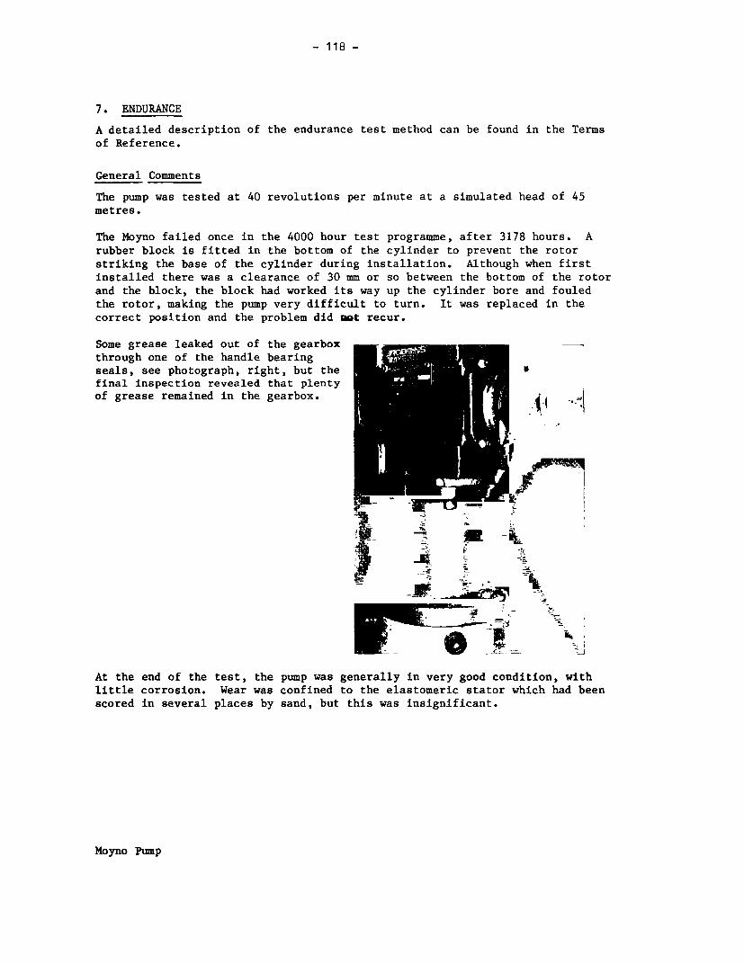
- 118 -
7. ENDURANCE
A detailed description of the endurance test method can be found in the Termsof Reference.
General Comments
The pump was tested at 40 revolutions per minute at a simulated head of 45metres.
The Moyno failed once in the 4000 hour test programme, after 3178 hours. Arubber block is fitted in the bottom of the cylinder to prevent the rotorstriking the base of the cylinder during installation. Although when firstinstalled there was a clearance of 30 mm or so between the bottom of the rotorand the block, the block had worked its way up the cylinder bore and fouledthe rotor, making the pump very difficult to turn. It was replaced in thecorrect position and the problem did not recur.
Some grease leaked out of the gearboxthrough one of the handle bearingseals, see photograph, right, but the S
final inspection revealed that plentyof grease remained in the gearbox.
-~ ~ I e-_
At the end of the test, the pump was generally in very good condition, withlittle corrosion. Wear was confined to the elastomeric stator which had beenscored in several places by sand, but this was insignificant.
Moyno Pump

- 119 -
Breakdown Incidence
Breakdowns are shown in bold type.
Hours: 1072 2044 3060 4063
l 3178
Rotorl Seized
Inspection Inspection Inspection Inspection Inspectionand full and volume and volume and volume and fullperformance flow flow flow performancetest test
Details of the Endurance Test
Breakdowns are shown in bold type.
HOURS
1072 INSPECTION after 1st 1000 hours:
(a) Rotor marked by particle of swarf - origin unknown(b) No corrosion
2044 INSPECTION after 2nd 1000 hours:
(a) Grease leaking from handle bearing seal in gearbox(b) No corrosion
3060 INSPECTION after 3rd 1000 hours:
(a) Grease leaking from handle bearing seal in gearbox(b) No corrosion
3178 Pump very stiff indeed. Dismantled - rubber block at lower end ofcylinder entangled in end of rotor. Reassembled and test continued withall original parts
Estimated amount of water pumped to breakdown ...... 1.2 million litres
Moyno Pump

120 -
HOURS
4063 FINAL INSPECTION
1. Pumpstand In good condition throughout
2. Cylinder Assembly (a) Rubber stator grooved by sand particles,but still serviceable
(b) Steel rotor in good condition, highlypolished
(c) Considerable quantity of sand in foot
valve, though still working
3. Corrosion No significant corrosion, though paint flaking
off cylinder housing
Estimated total amount of water pumped in 4000 hours ..... 1.5 million litres.
Leakage TestsVolume Flow Tests at 45m (litres) at 7 m (ml/min)
Revs/min 30 40 50
New 0.16 0.16 0.17 less than 0.1
After 1000 hours 0.15 0.16 0.18 less than 0.1
After 2000 hours 0.17 0.18 0.19 less than 0.1
After 3000 hours 0.14 0.16 0.17 less than 0.1
After 4000 hours 0.17 0.18 0.19 less than 0.1
Pump Performance after Endurance
HEAD 7 m 25 m 45 m
Nominal pumpingrate (revs/min) 30 40 50 30 40 50 30 40 50
Vol/revs (litres) 0.23 0.23 0.23 0.21 0.21 0.22 0.17 0.18 0.19
Work input/revs (J) 75 68 70 101 88 94 147 137 144
Efficiency (%) 20 22 22 51 59 57 49 58 58
If compared with the original performance data, these results show a marked
general reduction in the work input requirement, with a consequent increase
in efficiency. This suggests that slight wear of the stator rubber has
reduced the amount of deformation taking place.
Moyno Pump

- 121 -
8. ABUSE TESTS
8.1 Side Impact Tests The pump was undamaged in the side impact tests.
9. VERDICT
A robust pump, in good condition after 4000 hours of endurance testing.The rate of delivery was low, and the pump was hard work to operate at first,though it became slightly less hard with further use. Although generallyreliable in these tests, any repairs needed in the field will be difficultand expensive. It may not be ideal for community water supply because ofthe difficulties of operation and low rate of delivery. Expensive.
Moyno Pump
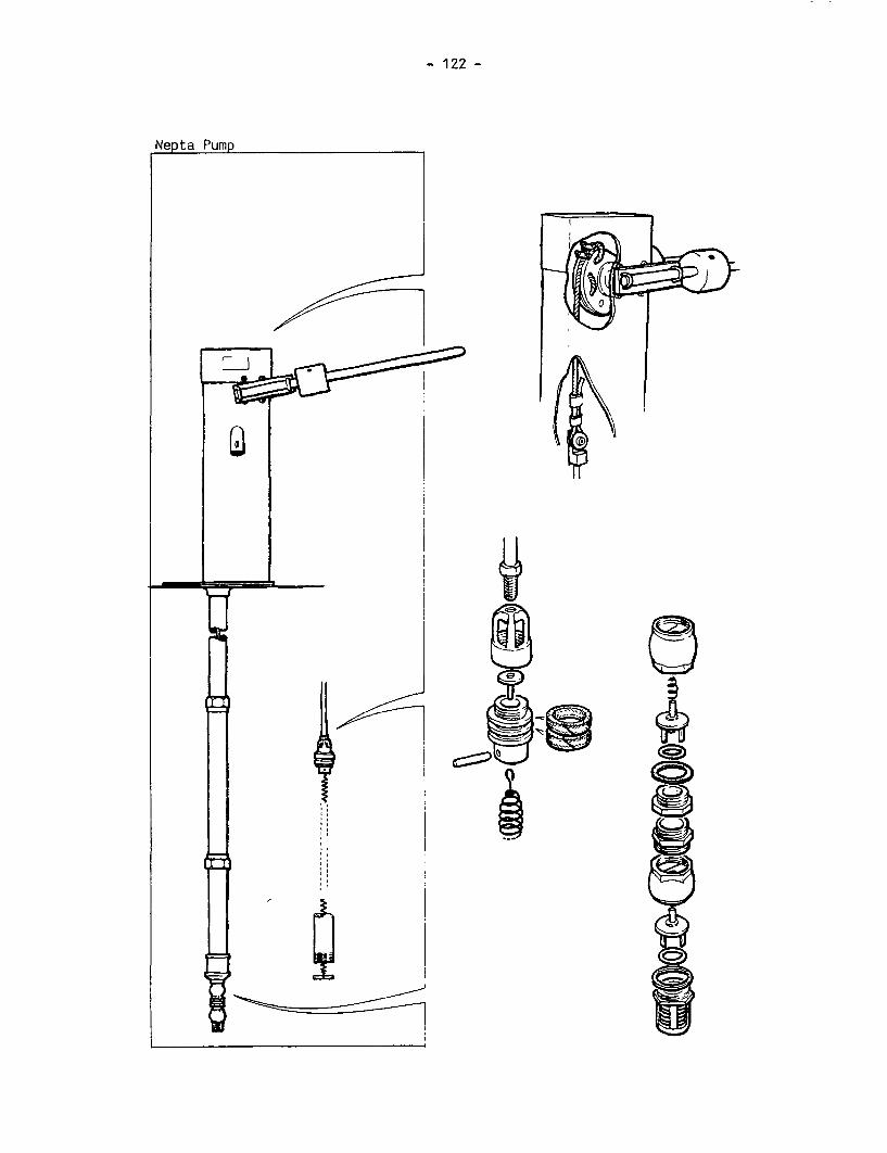
- 122 -
Nepta Pump
~~~~~z '
_ _ _ _ _ _ Iotjg g~~~~~~~~~~~~~~~~~~~~~~~~~~~~~~~~~~~~~~~~~~~~~~~~~~~~~~~~~~~~~~~~~~~~~~~~~~~~

- 123 -
BRIAU NEPTA
1.1 Manufacturer Briau SA
Address BP 0903,37009 Tours Cedex,FRANCE
1.2 Description The Nepta is a deep-well force pump, made in France.The pumpstand body is fabricated from sheet steel, thehandle mechanism machined and fabricated from steelsections. The body is protected by a coating of nylon,the handle is galvanised. The pump rods are stainlesssteel attached at the top to approximately one metre ofpolyester cord, which wraps around a machined sectorattached to the handle.
The cylinder is seamless brass tube. The machinedplunger uses two sealing rings of square-section textilecord in place of conventional cup seals. Tension in thepump rod and polyester cord is provided by a stainlesssteel spring attached to the bottom of the plunger. Twofoot valves are fitted, of similar design, each using arubber 0-ring seal.
1.3 Price in 1982 $650, supplied with 20 m below-ground assembly
2. INSPECTION
2.1 Packaging These pumps were very well packaged. All the componentsexcept the drop pipe were contained in wooden packingcases.
The pipes were bound together in groups of four. Thethreaded ends of the pipes were protected by plasticcaps, surrounded by wood shavings and wrapped in smallplastic sacks.
2.2 Condition as Both samples appeared to be in working order asReceived received, in spite of minor defects. The plungers in
both samples were not assembled tight, and oneplunger-to-pump rod joint was not tight enough.Although not of immediate significance, these defectsmight cause premature failure if not remedied beforeinstallation. The nylon coating on the spout of onepumpstand had been damaged in transit.Once installed, however, a more significant defectcame to light. The pump would work at shallow depths,but was unsatisfactory at 25 metres and very poor at45 metres. The reason was found to be leakage past
Nepta Pump

- 124 -
2.2 Condition as the plunger seals, caused by wrongly-sized sealingReceived (cont.) cords - see photograph, below. The cords appeared
to have been cut to length to suit the machinedgrooves in the plunger, and with butt joints - as aresult they were a poor fit in the cylinder in bothsamples.
. ~~~~V
Spare cord had been supplied with the pumps, and newsealing rings were cut to suit the cylinder bore, andwith angled, scarf joints. This markedly improved thepump efficiency, from 37% to 71% at 25 metres depth.
2.3 Installation & Maintenance Information
A booklet was supplied with the pumps, giving helpful instructions forinstallation. The instructions were in French, but were wellillustrated and useful.
3. WEIGHTS and MEASURES
3.1 Weights Pumpstand 41.5 kgCylinder assembly 15.5 kgPump rods 0.7 kg per metre
3.2 Dimensions Nominal cylinder bore: 50 mmActual pump stroke: 203 mmNominal volume per stroke: 399 mlDrop pipe size: 1.25 inchesOutside diameter of below-ground assembly: 76 mmPump rod diameter: 10 mmMaximum usable cylinderlength: 620 mm
Nepta Pump

- 125 -
3.3 Cylinder Bore
No significant taper or ovality was found in either of the
samples.
The surface roughness average (Ra) was measured in three places
in a direction parallel to the cylinder axis.
SAMPLE CYLINDER BORE ROUGHNESS AVERAGE (pm)
TEST 1 TEST 2 TEST 3 MEAN
1 Extruded brass 0.05 0.06 0.06 0.06
2 Extruded brass 0.22 0.18 0.22 0.21
Measured at 0.25 mm cut-off
3.4 Ergonomic Measurements
HANDLE HEIGHT PLATFORM ANGULAR HANDLE VELOCITY HEIGHT
HEIGHT MOVEMENT LENGTH RATIO OF OF SPOUT
MAX"1 ) MIN(1 ) (mm) OF HANDLE (mm) HANDLE (mm)
(mm) (mm) (degrees)
1413 190 0 104 780 7.0:1 530
(1) Measured without compressing bump stops.
4. ENGINEERING ASSESSMENT
4.1 Materials of Construction
COMPONENT MATERIAL(S)
Pumpstand Fabricated steel, nylon-coated
Handle and Steel, galvanisedcounterweights
Bearings Mild steel shafts in plain bronze
shell bearingsQuadrant assembly Fabricated steel, galvanised
Cylinder Extruded brass
Plunger Cast gunmetal or brass
Plunger seals Textile cordDrop pipe Galvanised steel
Pump rods Stainless steel with polyestercable coupling at pumpstand
Nepta Pump

- 126 -
4.2 Manufacturing Techniques
The manufacturing techniques required to make the pump are listed below:-
Above-ground Steel fabricationAssembly Sheet metal forming
MachiningRubber mouldingPlating
The pumpstand body is fabricated from formed sheet steel and coated with plasticfor corrosion resistance. The machining of the pivot shaft and cable quadrantassembly requires careful quality control. The polyester cable at the top ofthe pump rod is a proprietary item.
Below-ground Brass/gunmetal foundryAssembly Hot pressing of brass
MachiningRubber moulding
Care in needed in fitting the plunger packing to ensure a satisfactory seal inthe cylinder bore.
4.3.1 Ease of Installation
Clamps and hexagon keys were supplied with the test samples. This pump needsattention to the final adjustments of the polyester cord and the handlecounterweights. Care is needed to ensure a sanitary seal at the wellhead.
4.3.2 Ease of Pumpstand Maintenance and Repair
This pumpstand is unlikely to require frequent maintenance, and need not beremoved from the wellhead. The bearings may be replaced when necessary; ahexagon key is needed, but this was supplied by the manufacturer.
Nepta Pump

- 127 -
4.3.3 Ease of Below-ground Maintenance and Repair
AX 4g ftRepairs require removal of the complete below-ground assembly. The valves use0-ring seals which are easy to replace once the cylinder has been dismantled.If the spring is retained, it is likely to demand frequent replacement; careis then needed to avoid damage to the plunger.
4.4 Resistance to Contamination and Abuse
4.4.1 Resistance to Contamination
The pumpstand is adequately sealed against contamination, provided care istaken to seal the base of the pumpstand to the wellhead.
4.4.2 Likely Resistance to Abuse
The rather thin baseplate could be susceptible to abuse but fixings are mostlysecure.
4.5 Potential Safety Hazards
The handle on the pump is particularly heavy and would be dangerous if thepolyester cord were to break in use.
There are a number of potential fingertraps between the handle and thepumpstand, see photograph.Increased clearances would helpconsiderably.
Nepta Pump

-.128 -
4.6 Suggested Design Improvements
The plunger sealing rings should becut to length to suit the cylinderbore rather than the machined groovesin the plunger body, and the jointsshould be cut at an angle, as shown,right. The manufacturer has adoptedthis suggestion.
The efficiency of the plunger valve may be improved by providing a rubber orleather valve seat.
The tension spring below the plunger should be omitted. In deep-wellapplications, the weight of the pump rods should be sufficient to maintaintension in the polyester cord. In shallower applications, thicker, heavier
rods or additional weight added to the plunger may be needed.
The baseplate should be strengthened to avoid distortion.
Either the setting instructions for the plunger position should be improved or
the cylinder length should be increased.
5. PUMP PERFORMANCE
5.1 Volume Flow, Work Input and Efficiency
The description of the method can be found in the Test Procedure
HEAD 7 m 25 m 45 m
Nominal pumpingrate (strokes/min) 30 40 50 30 40 50 30 40 50
Vol/stroke (litres) 0.39 0.40 0.39 0.38 0.39 0.40 0.38 0.39 0.39
Work input/stroke (J) 51 45 43 130 123 120 206 216 180
Efficiency (%) 52 60 61 71 76 80 81 78 94
5.2 Leakage Tests
The measured leakage from the foot valve was not significant, i.e less than
0.1 ml/minute, for heads of 7, 25 and 45 metres.
Nepta Pump

- 129 -
6. USER TRIAL
6.1 User Responses
Details of the organisation of this trial can be found in the Test Procedure,and the statistical analysis of the user responses is presented in Appendix I.
6.2 Observations
Many users complained that the handle was too low. The handle moves through awide arc, 1040 for a full stroke. The users were keen to try for a fullstroke because of the relatively slow rate of delivery of the pump but theyfound the exaggerated body movements uncomfortable.
7. ENDURANCE
A detailed description of the endurance test method can be found in the TestProcedure.
General Comments
The pump was tested at 40 strokes per minute at a simulated head of 45 metres.
The only failures in the 4000 hour endurance test were of the tension spring.The spring broke and was replaced during the first 1000 hour period. 289hours later the replacement spring broke and was replaced. It was notreplaced when it broke for the third time since the pump seemed to worksatisfactorily without the spring. The pump completed the last 1000 hours ofthe test without a spring.
In the final inspection, all the valves were found to be in good condition,though there were signs of wear. The upper sealing ring on the plunger wasnoticeably worn, but the lower ring was in good condition and working well.The cylinder bore was in very good condition, with no signs of wear. There wassome play in the handle bearings, but they were still serviceable.
Breakdown Incidence
Breakdown shown in bold type.
Hours: 1072 2044 3060 4063I 1318 l
Spring Ireplaced l
Inspection Inspection Inspection Inspection Inspectionand full and volume and volume and volume and fullperformance flow. Spring flow flow performancetest replaced test
Nepta Pump

- 130 -
Details of the Endurance Test
HOURS
290 Pump noisy - pump rod striking rising main and/or pumpstand. Delivery
satisfactory therefore no action
1072 INSPECTION after 1st 1000 hours:
(a) Return spring in base of cylinder broken - replaced
(b) No corrosion
1318 Pump noisy - spring broken again - replaced
Estimated amount of water pumped to breakdown ....... 1.3 million litres
2044 INSPECTION after 2nd 1000 hours:
(a) Return spring satisfactory(b) Upper packing in plunger slightly loose in groove - lower satisfactory
(c) Handle bearings slightly worn(d) Thread stripped in cord clamp - longer bolt fitted
3060 INSPECTION after 3rd 1000 hours:
(a) Return spring broken - not replaced, pump performance satisfactory
without spring(b) Upper packing in plunger loose but lower still satisfactory
(c) Handle bearings continuing to wear
4063 FINAL INSPECTION
1. Pumpstand Noticeable wear in handle bearings though stillserviceable
2. Cylinder (a) No sign of wear(b) Leather sealing washer in lower cap split
3. Plunger (a) Upper seal worn, lower seal satisfactory andstill serviceable
(b) Plunger valve in good condition
4. Foot Valves Both valves in good condition
5. Corrosion (a) Rust on quadrant within pumpstand(b) Rust inside pumpstand casing where surface
coating has been damaged(c) Some rust where galvanised iron pipe joins foot
valve body
Estimated total amount of water pumped in 4000 hours ..... 3.8 million litres.
Nepta Pump

- 131 -
Leakage TestsVolume Flow Tests at 45m (litres) at 7 m (ml/min)
Strokes/min 30 40 50
New 0.38 0.39 0.39 less than 0.1After 1000 hours 0.39 0.38 0.37 less than 0.1After 2000 hours 0.42 0.43 0.44 less than 0.1After 3000 hours 0.38 0.40 0.40 0.1After 4000 hours 0.42 0.43 0.41 less than 0.1
Pump Performance after Endurance
HEAD 7 m 25 m 45 m
Nominal PumpingRate (Strokes/min) 30 40 50 30 40 50 30 40 50
Vol/stroke (litres) 0.45 0.46 0.47 0.43 0.45 0.46 0.42 0.43 0.41
Work input/stroke (J) 56 62 69 147 159 170 324 351 320
Efficiency (%) 53 49 46 71 68 65 57 54 55
If compared with the original performance data the results at 45 m show amarked increase in the work input requirement, with a significant increasein volume flow at all depths. This suggests that during the test period theconformity of the packing rings to the cylinder bore has improved. This hasresulted in increased friction.
8. ABUSE TESTS
8.1 Side Impact Tests
The pumpstand baseplate tended to distort at 200 Joules impact on thehandle and 400 Joules and above on the centre of the pumpstand.
8.2 Handle Shock Test
After approximately 20,000 cycles the handle bump rubbers began to breakup, and the back of the pumpstand body was becoming distorted. The testwas terminated after 26,358 cycles because the excessive movement of thehandle eventually caused the plunger to jam in the top of the cylinder.
9. VERDICT
A reasonably robust and generally reliable pump, if the spring were designedout. The pump worked satisfactorily without the spring for the last 1000hours of the endurance test. Adequate performance of this pump depends onaccuracy of fitting the plunger seals. Potentially suitable for communitywater supply, but not suitable for manufacture in many developing countries.Preferred by smaller users. Expensive.
Nepta Pump

I ~ ~ ~ I
0 'd
X @ X~~~~~~dnd BAua>j
- Z.£L -

- 133 - -
KENYA
1.1 Manufacturer Atlas Copco Terratest Limited,
Address Enterprise Road,PO Box 40090,NAIROBI,Kenya.
1.2 Description The Atlas Copco Kenya, made in the country of itsname, is a conventional deep-well force pump. Thepumpstand is designed to an established, almosttraditional, pattern. It is made of wood, steel andstandard galvanised iron pipe and pipe fittings.The pumpstand is designed to clamp onto a 4 inchwell casing.
The cylinder is seamless brass tube, the plunger hasthree cup leathers and both plunger and foot valvescontains stainless steel balls. The foot valve hasa screw thread to allow it to be attached to theplunger, so that both plunger and foot valve may beextracted without removing the cylinder or risingmain, provided at least 2.5 inch pipe is used.
1.3 Price in 1981 $669
2. INSPECTION
2.1 Packaging The pumps were securely packed in a robust plywoodpacking case bound with steel strapping. Althoughstrong enough to resist rough treatment the size andweight of the package might make it difficult toman-handle.
2.2 Condition as The pumps were received in working order. However,Received in one sample the spout was partially blocked by
surplus zinc from galvanising, which would haverestricted the outflow of water, and there was ruston the pump rod connecting tubes and on the split pinsof both samples.
2.3 Installation & Maintenance Information None supplied with the pump.
Kenya Pump

'-134 -
3. WEIGHTS and MEASURES
3.1 Weights Pumpstand 67.0 kgCylinder assembly 6.5 kgPump rods 1.5 kg. per metre
3.2 DimensionsNominal cylinder bore: 59 mmActual pump stroke: 295 mmNominal volume per stroke: 807 mlDrop pipe size: 2 inchesOutside diameter of below-ground assembly: 84 mm
Pump rod diameter: 21.5 mm (0.5 inch galvanisedsteel pipe)
Maximum usable cylinder
length: 400 mm
3.3 Cylinder Bore No significant taper or ovality was found in either of the
samples.
The surface roughness average (Ra) was measured in threeplaces in a direction parallel to the cylinder axis.
SAMPLE CYLINDER BORE ROUGHNESS AVERAGE (jam)TEST1 TEST 2 TEST 3 MEAN
1 Extruded brass 0.09 0.08 0.09 0.09
2 Extruded brass 0.12 0.14 0.12 0.13
Measured at 0.25 mm cut off
3.4 Ergonomic Measurements
A platform is not required. The pumpstand is attached to the protruding
top of the well casing.
HANDLE HEIGHT PLATFORM ANGULAR HANDLE VELOCITY HEIGHTHEIGHT MOVEMENT LENGTH RATIO OF OF SPOUT
MAX(1) MINM1) (mm) OF HANDLE (mm) HANDLE (mm)
(mm) (mm) (degrees)
2075 320 0 61 1740 5.5:1 525
(1) Measured without compressing bump stops.
Kenya Pump

- 135 -
4. ENGINEERING ASSESSMENT
4.1 Materials of Construction
COMPONENT MATERIAL(S)
Fulcrum upright WoodHandle WoodBearings Mild steel pivot shafts bear on
drilled holes in woodOutlet elbow and spout Galvanised steel pipe fittingsGuide tube and links Mild steelCylinder Extruded brass, gunmetal end capsPlunger Gunmetal, stainless steel ball valveCup seals LeatherFoot valve Cast gunmetal, stainless steel ball
valve, leather sealPump rod Standard 0.5 inch galvanised pipe
4.2 Manufacturing Techniques
The manufacturing techniques required to make the pump are listed below:-
Above-ground Steel forging and weldingAssembly Basic machining
Woodwork
The pumpstand is simple to manufacture, requiring basic skills in steelfabrication, simple machining and woodwork. It is suitable for manufacture indeveloping countries where timber of a suitable quality is readily available.
Below-ground Brass/gunmetal foundryAssembly Machining
Leather craft
The below-ground assembly requires generally higher levels of manufacturingskill than the pumpstand. It would not be suitable for manufacture in somedeveloping countries.
Kenya Pump

- 136 -
4.3 Ease of Installation, Maintenance and Repair
4.3.1 Ease of Installation
AX*The 4 inch well casing must protrude at least 350 mm above ground, to attach
the fulcrum upright. The spout support should be concreted in. The below-
ground assembly will be heavy if 2.5 inch galvanised iron rising main is
used. Assembly would be straightforward with good diagrammaticinstructions.
4.3.2 Ease of Pumpstand Maintenance and Repair
The design of this pumpstand lends itself to innovative repair using
indigenous materials and should not be difficult.
4.3.3 Ease of Below-ground Maintenance and Repair
Provided 2.5 inch rising main is used, the plunger and foot valve may beextracted without removing the rising main, so lifting tackle would not beneeded.
4.4 Resistance to Contamination and Abuse
4.4.1 Resistance to Contamination
Sealed against surface water but needs a better seal at the top of the 4 inch
well casing.
4.4.2 Likely Resistance to Abuse
The split pins are easy to remove, nuts only a little more difficult.
Otherwise robust.
Kenya Pump

- 137 -
4.5 Potential Safety Hazards
The U-bolts attaching the wooden fulcrum upright to the rising main haveunnecessarily long ends which have not been deburred.
The reciprocating links could be dangerous to bystanders or children.
There are potential finger-traps between the handle and the fulcrum upright.
4.6 Suggested Design Improvements
The angle between the fulcrum upright and the well casing should be bettercontrolled to minimise the angular movement of the connecting links. Thebracket used on the Shinyanga pump version would be much more satisfactory.
KenyaXPump
Kenya Pump
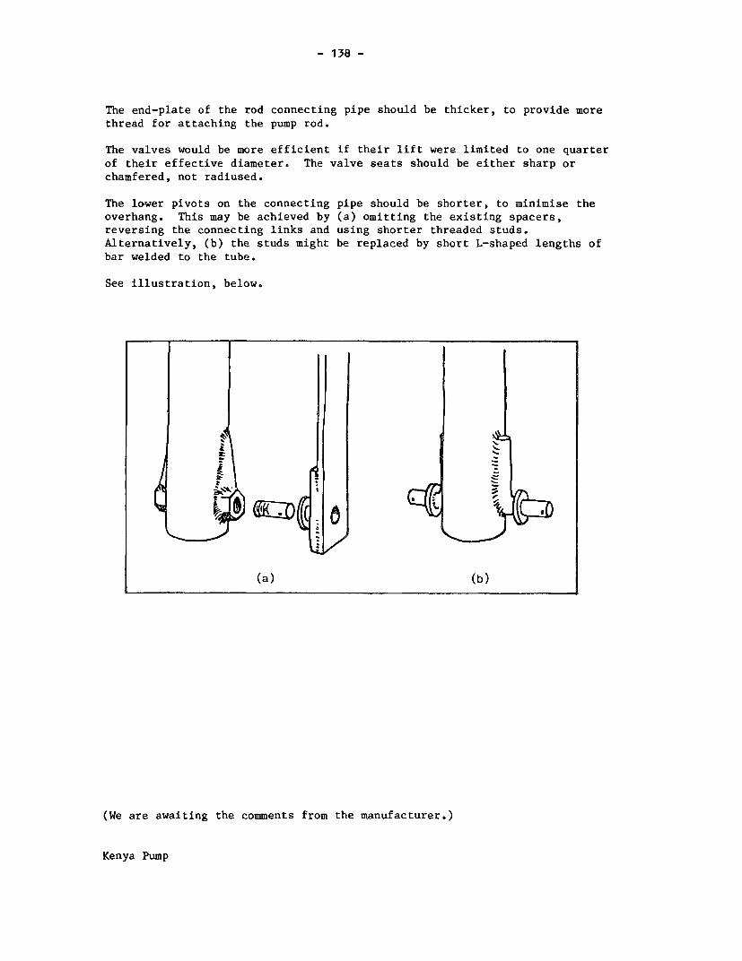
- 138 -
The end-plate of the rod connecting pipe should be thicker, to provide morethread for attaching the pump rod.
The valves would be more efficient if their lift were limited to one quarter
of their effective diameter. The valve seats should be either sharp orchamfered, not radiused.
The lo~wer pivots on the connecting pipe should be shorter, to minimise theoverhang. This may be achieved by (a) omitting the existing spacers,reversing the connecting links and using shorter threaded studs.Alternatively, (b) the studs might be replaced by short L-shaped lengths of
bar welded to the tube.
See illustration, below.
4L
(a) (b)
(We are awaiting the comments from the manufacturer.)
Kenya Pump

- 139 -
5. PUMP PERFORMANCE
5.1 Volume Flow, Work Input and Efficiency
The description of the method can be found in the Test Procedure.
HEAD 7 m 25 m 45 m
Nominal PumpingRate (strokes/min) 30 40 50 30 40 50 20 30 40
Vol/stroke (litres) 0.76 0.78 0.77 0.75 0.77 0.76 0.77 0.75 0.76
Work input/stroke (J) 119 122 141 271 300 290 500 493 528
Efficiency (%) 43 43 37 67 62 63 67 67 63
5.2 Leakage Tests
HEAD 7 m 25 m 45 m
Leakage rateml/minute 1.2 1.3 0.5
6. USER TRIAL
6.1 User Responses
Details of the organisation of this trial can be found in the TestProcedure, and the statistical analysis of user responses is presented inAppendix I.
6.2 Observations
At its highest point, the handle of this pump was out of reach of several ofthe children, and awkward for some smaller women. Full strokes neededexaggerated body movements with a change of grip, from pull to push in mid-stroke.
Kenya Pump
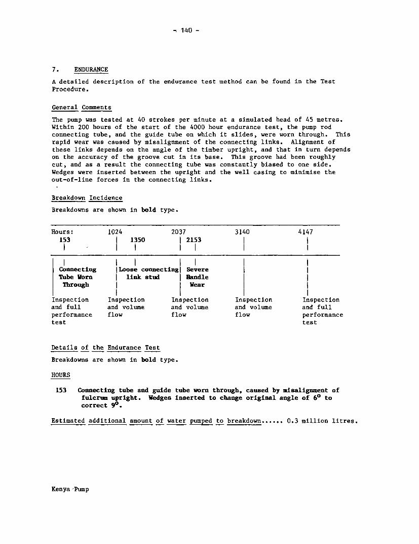
x 140 -
7. ENDURANCE
A detailed description of the endurance test method can be found in the Test
Procedure.
General Comments
The pump was tested at 40 strokes per minute at a simulated head of 45 metres.
Within 200 hours of the start of the 4000 hour endurance test, the pump rod
connecting tube, and the guide tube on which it slides, were worn through. This
rapid wear was caused by misalignment of the connecting links. Alignment of
these links depends on the angle of the timber upright, and that in turn depends
on the accuracy of the groove cut in its base. This groove had been roughly
cut, and as a result the connecting tube was constantly biased to one side.
Wedges were inserted between the upright and the well casing to minimise the
out-of-line forces in the connecting links.
Breakdown Incidence
Breakdowns are shown in bold type.
Hours: 1024 2037 3140 4147
153 1350 I 2153
l l l l l l I
Connecting ILoose connecting Severe ITube Vorn link stud Handle l
Through I Wear l
Inspection Inspection Inspection Inspection Inspection
and full and volume and volume and volume and full
performance flow flow flow performance
test test
Details of the Endurance Test
Breakdowns are shown in bold type.
HOURS
153 Connecting tube and guide tube worn through, caused by misalignment offulcrum upright. Wedges inserted to change original angle of 60 tocorrect 90.
Estimated additional amount of water pumped to breakdown ...... 0.3 million litres.
Kenya-Pump

- 141 -
HOURS
1024 INSPECTION after 1st 1000 hours:
(a) Handle fulcrum and connecting link bearings worn(b) Cracks in the wooden handle and the fulcrum upright, though both
still serviceable(c) Some corrosion at joint between plunger and pump rod
1350 One connecting link pin worked loose, causing severe wear ofconnecting tube and guide tube due to resultant misalignment. Stub pinsmodified in line with our suggested design improvement - (b) on page68.
Estimated additional amount of water pumped to breakdown ....... 2.3 million litres
2037 INSPECTION after 2nd 1000 hours:
(a) More wear in handle fulcrum - bearing hole elongated to about twiceoriginal size
(b) Cracks in handle have closed up - appears to have shrunk - handlefairly tight in fulcrum upright
(c) Ball valve cages in foot valve and plunger distorted - plunger worse
than foot valve(d) More corrosion at joint between plunger and pump rod
2153 Handle reversed to combat wear in pivot hole
Estimated additional amount of water pumped to breakdown ....... 1.4 million litres
3140 INSPECTION after 3rd 1000 hours:
(a) Slightly increased distortion of valve cages(b) Connecting tube and guide tube noticeably worn(c) More corrosion at joint between plunger and pump rod
Kenya Pump

- 142 -
4147 FINAL INSPECTION
1. Pumpstand (a) Connecting tube and guide tube considerably worn(b) All pivot holes in handle noticeably worn -
some severely
2. Cylinder Slightly scratched but no significant wear - generallyin good condition
3. Plunger (a) Valve cage distorted by hammering from valve ball(b) Valve seat pitted(c) Cup seals in good condition
4. Foot Valve (a) Valve cage distorted by hammering from valve ball,otherwise in good condition
(b) Sand has penetrated filter and accumulated infilter cap
5. Corrosion Considerable rust on plunger rod, otherwise littlecorrosion
Estimated total amount of water pumped in 4000 hours ....... 7.4 million litres
Leakage TestsVolume Flow Tests at 45m (litres) at 7 m (ml/min)
Strokes/min 20 30 40 50
New 0.77 0.75 0.76 - 1.2After 1000 hours - 0.75 0.75 0.75 0.5After 2000 hours - 0.68 0.68 0.69 0.7After 3000 hours - 0.69 0.70 0.70 0.3After 4000 hours 0.76 0.76 0.76 - 0.3
Pump Performance after Endurance
HEAD 7 m 25 m 45 m
Nominal PumpingRate (Strokes/min) 20 30 40 20 30 40 20 30 40
Vol/stroke (litres) 0.76 0.77 0.77 0.74 0.76 0.77 0.76 0.76 0.76
Work input/stroke (J) 195 210 211 370 378 381 572 581 594
Efficiency (%) 26 24 24 48 49 49 58 57 56
If compared with the original performance data, these results show a markedincrease in the work input requirements with a consequent reduction inefficiency. This suggests that bedding in has increased the frictionallosses and may largely be accounted for by the wear caused by the rubbing ofthe two steel guide tubes.
Kenya Pump
- 143 -
8. ABUSE TESTS
8.1 Side Impact Tests
The Kenya pump was undamaged by both the handle and body side impacttests. In the handle impact test, some of the energy was absorbed bythe pump slipping round the well casing.
8.2 Handle Shock Test
The pump did not break down in the handle shock test, but a burr formedon the bottom of the pump rod connecting tube which caused noticeablewear of the guide tube.
9. VERDICT
A simple but cumbersome pump. Likely to need frequent maintenance above-ground, much of which could be avoided by small design changes. Inparticular the endurance test showed that more accurate alignment of thefulcrum upright and replacement of the original link pivots greatlyincreased the durability of the pumpstand. Possibly suitable for communitywater supply. Very heavy below-ground and therefore difficult to extractrising main, but plunger and footvalve may be removed on rodding, and inmany respects could be maintained locally. Approaching a VLOM pump, butrequires that at least the upper part of the well casing be made of steel.Expensive.
NB. It would have been helpful to have had some reaction from themanufacturer.
Kenya Pump

4~~~~~~~~~~~~~~~~~~~~~~~~~~~~~~~~~~~~~~~~~~~~~~~~~~~~~~~~~~~~~~~~~~~~~~~~~~~~~~~~~~~~~~~~~~~~~~~~~~~~~~~~~~~~~~~~~~~~~~~~~~-. (V~~~~~~~~~~~~~~~~~~~~~~~~~~~~~~~~~~~~~~~~~~~~~~~~~~~~~~~~~~~~~~~~~~~~~~~~~~~~~~~~~~~~~~~~~~~~~~~~~~~~~~~~~~~~~~~~~~~
g~~~iIi I~~~~~~~j
i ~ ~ ~ ~ dnd9 0 ~
I 77

- 145 -
NEW NO. 6
1.1 Manufacturer Engineers Wood Steel Industries Ltd.,
Address 67 Tejgaon Industrial Area,DHAKA-8,Bangladesh
1.2 Description The New No. 6 is a shallow-well suction pump, made
in Bangladesh and constructed almost entirely ofcast iron. It is mounted directly onto a 1.5 inchrising main. The plunger uses a moulded PVC cupwasher. The check valve is a simple leather flap,weighted with cast iron.
It appears crude and rather rough at first sight,but is commendably simple and robust.
1.3 Price in 1981 $33
2. INSPECTION
2.1 Packaging The pumps were in a single wooden packing case withcorrugated cardboard lining.
The cardboard liner would be adversely affected bywater, but it and its contents were well supportedby the wooden case.
2.2 Condition as Both samples were received in working order.Received However, both pump tops were loose, spring washers
had been placed under the bolt heads rather thanunder the nuts. In one sample, the halves of theplunger were not tightly screwed together, and alocknut on the plunger rod was not tight. Althoughnot of immediate significance, both these defectsmight cause premature failure of the pump if notremedied before installation.
2.3 Installation & None supplied with the pump. Subsequently aMaintenance maintenance leaflet was received which contained veryInformation helpful diagrams.
New No.6 Pump

- 146 -
3. WEIGHTS and MEASURES
3.1 Weights Pumpstand 31.0 kg
3.2 Dimensions Nominal cylinder bore: 90 mmActual pump stroke: 219 mmNominal volume per stroke: 1393 mlDrop pipe size: 1.5 inches
3.3 Cylinder Bore No significant taper or ovality was found in either of the
samples.
The surface roughness average (Ra) was measured in threeplaces in a direction parallel to the cylinder axis
SAMPLE CYLINDER BORE ROUGHNESS AVERAGE (am)
TEST 1 TEST 2 TEST 3 MEAN
1 Machined cast iron 2.3 2.5 2.5 2.4
2 Machined cast iron 2.0 2.5 2.8 2.4
Measured at 0.25 mm cut-off
3.4 Ergonomic Measurements The pumpstand is mounted directly on the top of
the rising main.
HANDLE HEIGHT PLATFORM ANGULAR HANDLE VELOCITY HEIGHTHEIGHT MOVEMENT LENGTH RATIO OF OF SPOUT
MAX(1) MIN(1) (mm) OF HANDLE (mm) HANDLE (mm)
(mm) (mm) (degrees)
1190 400 280(2) 100 595 4.7:1 583
(1) Measured without compressing bump stops.(2) Height of protruding rising main
New No.6 Pump

- 147 -
4. ENGINEERING ASSESSMENT
4.1 Materials of Construction
COMPONENT MATERIAL(S)
Pumpstand body Cast ironHandle Cast ironBearings Mild steel pivot shafts bear on holes
drilled in iron castingsPlunger Cast ironCup seal Moulded PVCBase valve Leather
4.2 Manufacturing Techniques
The manufacturing techniques required to make the pump are listed below:-
Iron FoundrySimple machiningPlastic mouldingLeather crafting
The New No.6 is well-suited for manufacture in developing countries whereadequate skills in iron foundry work and basic machining are available. Thepump has been designed intelligently to avoid close tolerances in casting ormachining.
For example, the holes for the handlepivot pins are deliberately drilledoversize to avoid any problems arisingfrom misalignment - see photograph,right.
., No.6' Puip
New No.6 Pump

- 148 -
4.3 Ease of Installation, Maintenance and Repair
4.3.1 Ease of Installation
The drop pipe must be securely installed to support the pumpstand, otherwise
this suction pump is easy to install. Only basic tools and skills are
required.
4.3.2 Ease of Maintenance and Repair
This pump is likely to require frequent attention to the plunger and check
valve, but is very simple. Most jobs can be done with flat spanners and
pliers. A pipe wrench may be needed to dismantle the plunger, which may
become heavily corroded.
4.4 Resistance to Contamination and Abuse
4.4.1 Resistance to Contamination
The pumpstand is open at top where the connecting rod passes through the top.
4.4.2 Likely Resistance to Abuse
The cast iron handle and pump top are susceptible to accidental damage. The
attachment to rising main is potentially weak: the whole pump might be too
easily detached. The pivot pins and bolts are easy to remove.
4.5 Potential Safety Hazards
Split pins, with sharp ends, are used to retain the pivot pins for the handle.
4.6 Suggested Design Improvements
A sliding plate on the connecting rod (in the manner of the Bandung pump)
would help to prevent contamination.
The diameter of the rising main should be increased and/or cast mounting lugs
should be provided on the pumpstand to provide a more secure mounting at the
wellhead.
The quality of the bore should be improved to reduce the rapid wear of the cup
washer.
New No.6 Pump

- 149 -
The handle casting pattern should be modified to provide a small bulge at theend to avoid hands slipping off the polished surface.
A small change to the casting patternfor the pump top could increase thestrength of the handle fulcrumextensions and act as guides for asliding plate - see illustration.
5. PUMP PERFORMANCE
5.1 Volume Flow, Work Input and Efficiency
The description of the method can be found in the Test Procedure.
HEAD 7 m
Nominal pumpingrate (strokes/min) 20 30 40
Vol/stroke (litres) 1.30 1.20 1.29
Work input/stroke (J) 148 121 134
Efficiency (%) 59 67 65
5.2 Leakage Tests
Leakage at 7 m head was 0.25 ml/minute. Leakage of the check valve will meanthat the pump will require frequent priming with consequent risk ofcontamination.
New No.6 Pump

- 150 -
6. USER TRIAL
6.1 User Responses
Details of the organisation of this trial can be found in the TestProcedure, and the statistical analysis of user responses is presented in
Appendix I.
6.2 Observations
Many users were pleasantly surprised by the performance of this pump,contrasted with its crude appearance. It delivered plenty of water for eachstroke, and the handle movement allowed arms, shoulders, back and legs to
contribute. Some disliked the roughness of the handle.
7. ENDURANCE
A detailed description of the endurance test method can be found in the TestProcedure.
General Comments
The pump was tested at 30 strokes per minute at 7 metres head.
The original cup washer and plunger valve were badly worn after 1000 hours,and were replaced. The cup washer failure was probably due to the initial
roughness of the bore. The replacements lasted the remaining 3000 hours ofthe test programme, though both were badly worn at the end. The check valvewas also replaced at 1000 hours, and the replacement also lasted out theremainder of the 4000 hours.
The final inspection revealed wear in the handle pivot shafts and the
associated holes in the handle, pump top and connecting rod eye. The pump was
still working however, and would probably continue for some time.
Corrosion was extensive. The cast iron pumpstand has no protective coating andwas rusting wherever it had got wet. Because of rust the plunger was impossibleto dismantle and the retaining screw could not be removed from the check valveweight.
The cylinder was in good condition at the end of the test. The original
machining marks in the bore were still clearly visible although the high spotshad been removed.
New No.6 Pump

- 151 -
Breakdown Incidence
Breakdowns are shown in bold type.
Hours: 1072 2044 3060 4063
Cup Washer and lCheck Valve lWorn Out
Inspection Inspection Inspection Inspection Inspectionand full and volume and volume and volume and fullperformance flow flow flow performancetest test
Details of the Endurance Test
Breakdowns are shown in bold type.
HOURS
1072 INSPECTION after 1st 1000 hours:
(a) Volume flow test results poor, approx. 50Z of original conditiondata. New cup washer and plunger valve fitted. Check valve veryhard, also replaced - performance restored.
(b) Some surface rust on most parts of pump
Estimated additional amount of water pumped to breakdown ....... 2.3 million litres
2044 INSPECTION after 2nd 1000 hours:
(a) Cup washer hard and stiff but otherwise in good condition(b) Slight wear on side of plunger valve - seating satisfactory(c) Check valve in good condition(d) Noticeable wear in handle fulcrum components(e) More surface rust on most parts of pump
3060 INSPECTION after 3rd 1000 hours:
(a) Plunger seal hard and stiff but working satisfactorily(b) Slightly more wear on plunger valve, but still satisfactory(c) More wear in handle fulcrum components though still serviceable(d) More surface rust on most parts of pump
New No.6 Pump

- 152 -
4063 FINAL INSPECTION
1. Pump Body (a) Pivot holes in handle, pump top and connecting rod
and handle eye all noticeably worn - pins also worn though
still serviceable(b) Cylinder bore somewhat less rough than when nev,
but machining marks still clearly evident - nosignificant wear
2. Plunger (a) Cup seal badly worn(b) Plunger valve noticeably worn on its circumference
- both valve faces also worn
3. Check Valve Leather flap deeply indented
4. Corrosion (a) Plunger could not be dismantled because of rusted
screw threads(b) Check valve weight could not be removed from
leather flap because of corrosion of retainingscrew
(c) Considerable rust on unprotected cast iron of pumpbody, but no effect on pump performance
Estimated total amount of water pumped in 4000 hours ..... 8.6 million litres
Leakage TestsVolume Flow Tests at 7 m (litres) at 7 m (ml/min)
Strokes/min 20 30 40
New 1.31 1.20 1.29 0.3
After 1000 hours 0.58 0.86 1.05 4.0
After 2000 hours 0.82 1.02 1.07 0.4
After 3000 hours 1.00 1.18 1.16 less than 0.1
After 4000 hours 0.48 1.01 0.93 8.6
Pump Performance after Endurance
HEAD 7 m
Nominal PumpingRate (Strokes/min) 20 30 40
Vol/stroke (litres) 0.48 1.01 0.93
Work input/stroke (J) 73 129 141
Efficiency (%) 45 53 45
These results are not comparable with the original performance test data
because the plunger seal was replaced during the performance test.
New No.6 Pump

- 153 -
8. ABUSE TESTS
8.1 Side Impact Tests
The pump failed in one of the side impact tests. In the body test, thethread in the pumpstand base was partially stripped at an impact of 300Joules on the centre of the pumpstand. However, plenty of threadremained, and the pump could have been remounted and re-used. In thetest on the handle, the pumpstand simply turned on its mounting thread to
absorb the impact.
8.2 Handle Shock Test
The pump completed its allotted 72,000 cycles without failure.
9. VERDICT
A very simple, cheap and sturdy suction pump. Needs to be primed and thereforesusceptible to contamination and abuse, hence not very suitable for drinkingwater supply. Initial roughness of the bore causes early failure of the cup
washer and should be improved. Likely to wear considerably when heavilyused. Suitable for manufacture in developing countries with iron foundryskills.
New No.6 Pump

- 154 -
Nira Pump
S Uit01

- 155 -
NIRA AF-76
1.1 Manufacturer Vammalan Konepaja oy,
Address 38200 Vammala,FINLAND.
1.2 Description The Nira is a deep-well force pump, made in Finland.The pumpstand has a tubular steel column with a castiron base, and a cast iron handle socket and spoutassembly. The handle was originally steel bar but hassince been changed to steel tube. The steel parts ofthe pumpstand are galvanised, the iron castings areprotected by a nylon coating.
The 76 mm bore cylinder is seamless brass tube withthreaded collars soft-soldered to each end. The cupwasher and plunger valve are combined in a singlerubber moulding. The foot valve is of similar
design, also moulded in rubber.
1.3 Price in 1982 $203 Pump and cylinder
2. INSPECTION
2.1 Packaging Delivered in a single large wooden packing case 3.5 mlong.
The packaging was strong but its size and weight wouldmake it difficult to man-handle. On the other hand, bypacking all the components in a single case, the chanceof components being separated in transit is much reduced.
2.2 Condition as Both pumpstands were in working order as received.Received However, one cylinder was externally damaged causing
distortion of the bore, and several fixings wereinsufficiently tight. Although the pumps were inworking order, these defects would be likely to causepremature failure if not remedied before installation.
2.3 Installation & A promotional leaflet was supplied with the pumps.Maintenance It included an annotated sketch of the components,Information but was not very helpful.
Nira Pump

- 156 -
3. WEIGHTS and MEASURES
3.1 Weights Pumpstand 29.5 kgCylinder assembly 4.0 kgRising main 5.2 kg/metrePump rods 0.7 kg/metre
3.2 Dimensions Nominal cylinder bore: 76 mmActual pump stroke: 127 mmNominal volume per stroke: 576 mlDrop pipe size: 2 inchesOutside diameter of below-ground assembly: 95 mmPump rod diameter: 10 mmMaximum usable cylinderlength: 310 mm
3.3 Cylinder Bore No significant taper or ovality was found in any of thesamples.
The surface roughness average (Ra) was measured in threeplaces in a direction parallel to the cylinder axis.
SAMPLE CYLINDER BORE ROUGHNESS AVERAGE Qum)TEST 1 TEST 2 TEST 3 MEAN
1 Extruded brass 0 06 0.07 0.06 0.06
2 Extruded brass 0.12 0.11 0.11 0.11
Measured at 0.25 mm cut-off
3.4 Ergonomic Measurements
HANDLE HEIGHT PLATFORM ANGULAR HANDLE VELOCITY HEIGHTHEIGHT MOVEMENT LENGTH RATIO OF OF SPOUT
MAX( 1 ) MINM1 ) (mm) OF HANDLE (mm) HANDLE (mm)
(mm) (mm) (degrees)
1155 542 0 58 623 5.0:1 603
(1) Measured without compressing bump stops.
Nira Pump
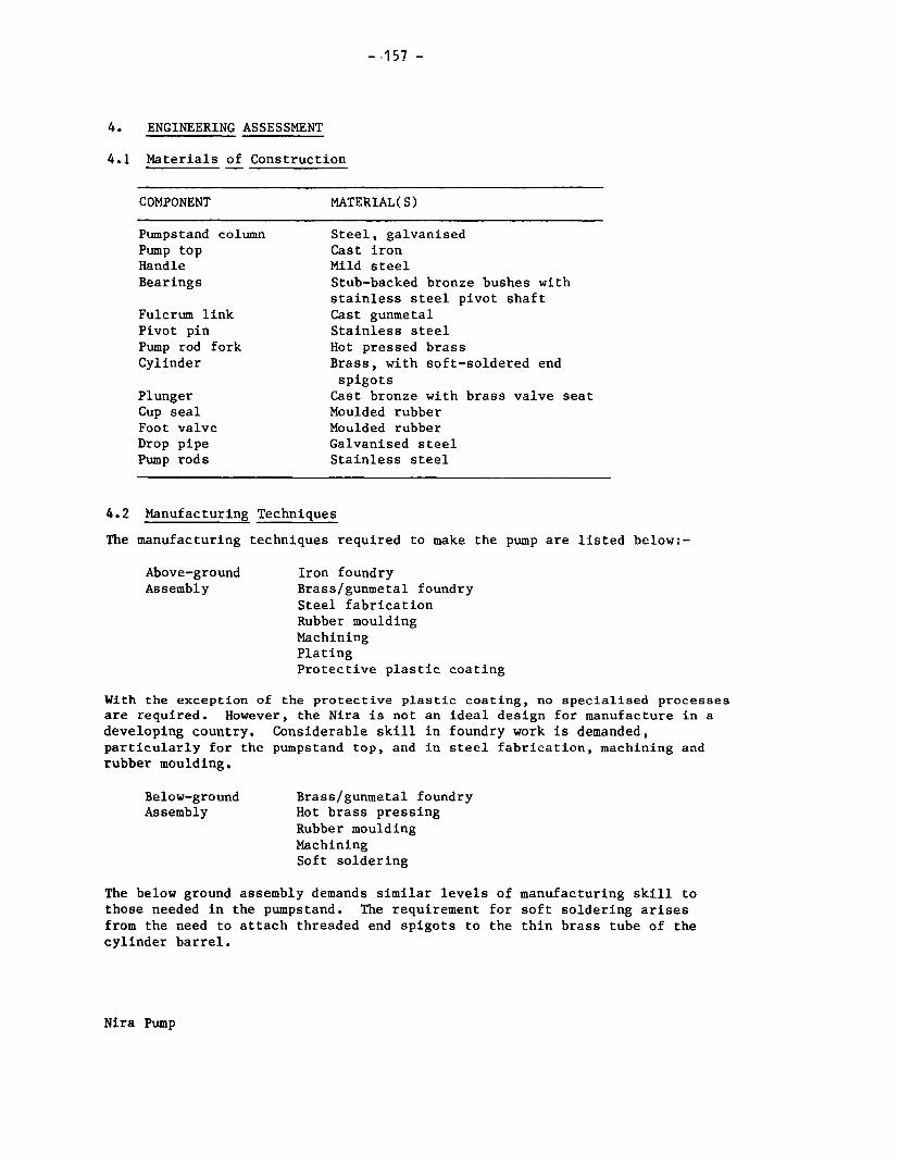
- -157 -
4. ENGINEERING ASSESSMENT
4.1 Materials of Construction
COMPONENT MATERIAL(S)
Pumpstand column Steel, galvanisedPump top Cast ironHandle Mild steelBearings Stub-backed bronze bushes with
stainless steel pivot shaftFulcrum link Cast gunmetalPivot pin Stainless steelPump rod fork Hot pressed brassCylinder Brass, with soft-soldered end
spigotsPlunger Cast bronze with brass valve seatCup seal Moulded rubberFoot valve Moulded rubberDrop pipe Galvanised steelPump rods Stainless steel
4.2 Manufacturing Techniques
The manufacturing techniques required to make the pump are listed below:-
Above-ground Iron foundryAssembly Brass/gunmetal foundry
Steel fabricationRubber mouldingMachiningPlatingProtective plastic coating
With the exception of the protective plastic coating, no specialised processesare required. However, the Nira is not an ideal design for manufacture in a
developing country. Considerable skill in foundry work is demanded,particularly for the pumpstand top, and in steel fabrication, machining andrubber moulding.
Below-ground Brass/gunmetal foundryAssembly Hot brass pressing
Rubber mouldingMachiningSoft soldering
The below ground assembly demands similar levels of manufacturing skill tothose needed in the pumpstand. The requirement for soft soldering arisesfrom the need to attach threaded end spigots to the thin brass tube of thecylinder barrel.
Nira Pump

- 158 -
4.3 Ease of Installation, Maintenance and Repair
4.3.1 Ease of Installation
The manufacturer supplied thread locking compound with the test samples. Agrease gun is needed to lubricate the handle bearing. The below-groundassembly will be heavy, but in other respects installation is straightforwardproviding care is taken in handling the cylinder to avoid damaging the thinwall, and cutting the pump rod to the correct length.
4.3.2 Ease of Pumpstand Maintenance and Repair
The pumpstand is easy to dismantle, and does not need to be removed from thewellhead. The handle bearings would be easy to replace in a workshop; in thefield, replacement of the complete fulcrum casting might be required.
4.3.3 Ease of Below-ground Maintenance and Repair
~ *Repairs require removal of the complete below-ground assembly. For plungerseals and foot valve, manufacturer's spares are essential. Again, care isneeded in handling the cylinder to avoid damaging the thin wall.
4.4 Resistance to Contamination and Abuse
4.4.1 Resistance to Contamination
The pump could be affected by surface water - otherwise very sanitary.
4.4.2 Likely Resistance to Abuse
Pump head could be unscrewed from column but otherwise fixings secure. Handlequite easy to remove - would not be easy to improvise a replacement.
4.5 Potential Safety Hazards
There are no significant safety hazards in this pump.
Nira Pump

- 159 -
4.6 Suggested Design Improvements
A thicker cylinder wall would be less easily dented and would allow integralthreads at each end, thereby eliminating the need for soft-soldered endspigots.
Valve lift should be reduced, ideally to one quarter of the diameter. Themanufacturer has adopted this suggestion.
In the newer, tubular handle, the core should be a tighter fit in the outertube, otherwise the core provides little support.
A stiffer base casting would be advantageous.
The manufacturer now uses stainless shouldered fixing screws with hexagonheads in the plunger, to control the compression of the rubber moulding.
The manufacturer has modified the handle fulcrum, to improve its ability to
resist side loads on the handle.
5. PUMP PERFORMANCE
5.1 Volume Flow, Work Input and Efficiency
The description of the method can be found in the Test Procedure.
HEAD 7 m 25 m 45 m
Nominal pumpingrate (strokes/min) 30 40 50 30 40 50 30 40 50
Vol/stroke (litres) 0.62 0.63 0.65 0.64 0.65 0.65 0.60 0.59 0.59
Work input/stroke (J) 55 59 72 264 209 254 395 398 404
Efficiency (%) 76 71 61 59 75 63 66 65 63
5.2 Leakage Tests
HEAD 7 m 25 m 45 m
Leakage rate (ml/min) 0.1 less than 0.1 less than 0.1
6. USER TRIAL
6.1 Use Responses
Details of the organisation of this trial can be found in the Test Procedure,and the statistical analysis of user responses is presented in Appendix I.
Nira Pump

- 160 -
6.2 Observations
Children and small women found this pump difficult because of the high levelsof effort required. Many children found it difficult to bring their weight tobear on the handle at the start of the downstroke.
7. ENDURANCE
A detailed description of the endurance test method can be found in the TestProcedure.
General Comments
The Nira was tested at 40 strokes per minute at a simulated depth of 36 metres,the maximum originally specified by the manufacturer. The handle broke severaltimes within the 4000 hours. The original, round bar handle broke after only314 hours. A new tubular handle was supplied by the manufacturer, but that inturn broke after a further 2200 hours or so, and a second sample 189 hourslater. One of the tubular handles was repaired by welding and completed theremainder of the 4000 hour test. In response, the manufacturer now recommendsthe 76 mm cylinder for a maximum depth of 18 metres, and will offer a 50 mmcylinder for greater depths.
At the 1000 hour intermediate inspection, all the setscrews used to assemble theplunger were badly corroded, and the head of one screw had broken off. Becauseof this the plunger could not be dismantled and was therefore replacedcompletely.
In the final inspection, little wear was found in the valves, cup seal, cylinderand handle bearings. The six setscrews in the plunger were corroded butunbroken. There was no significant corrosion elsewhere.
Breakdown Incidence
Breakdowns are shown in bold type.
Hours: 1072 2044 3060 4063314 l l 2828 l
_ I l l 1 30171
Handle andlIsBroken | Broken
Inspection Inspection Inspection Inspection Inspectionand full and volume and volume and volume and fullperformance flow flow flow performancetest test
Nira Pump

- 161 -
Details of the Endurance Test
Breakdowns are shown in bold type.
HOURS
314 Handle broken - replaced
Estimated amount of water pumped to breakdown ........ 0 .5 million litres
651 New tubular handle from Nira fitted
1072 INSPECTION after 1st 1000 hours:
(a) 1 of 6 setscrews in plunger broken - all 6 corroded(b) No significant corrosion elsewhere
2044 INSPECTION after 2nd 1000 hours:
(a) 6 setscrews in plunger corroded(b) No other corrosion(c) Slight side play in handle fulcrum
2828 Handle broken - replaced with 2nd new tubular type
Estimated additional amount of water pumped to breakdown ...... 3.9 million litres
3017 Handle broken - repaired
Estimated additional amount of water pumped to breakdown ....... 0 .3 million litres
3060 INSPECTION after 3rd 1000 hours:
(a) Slightly more side play in handle fulcrum(b) 6 setscrews in plunger more corroded(c) No other corrosion
Nira Pump
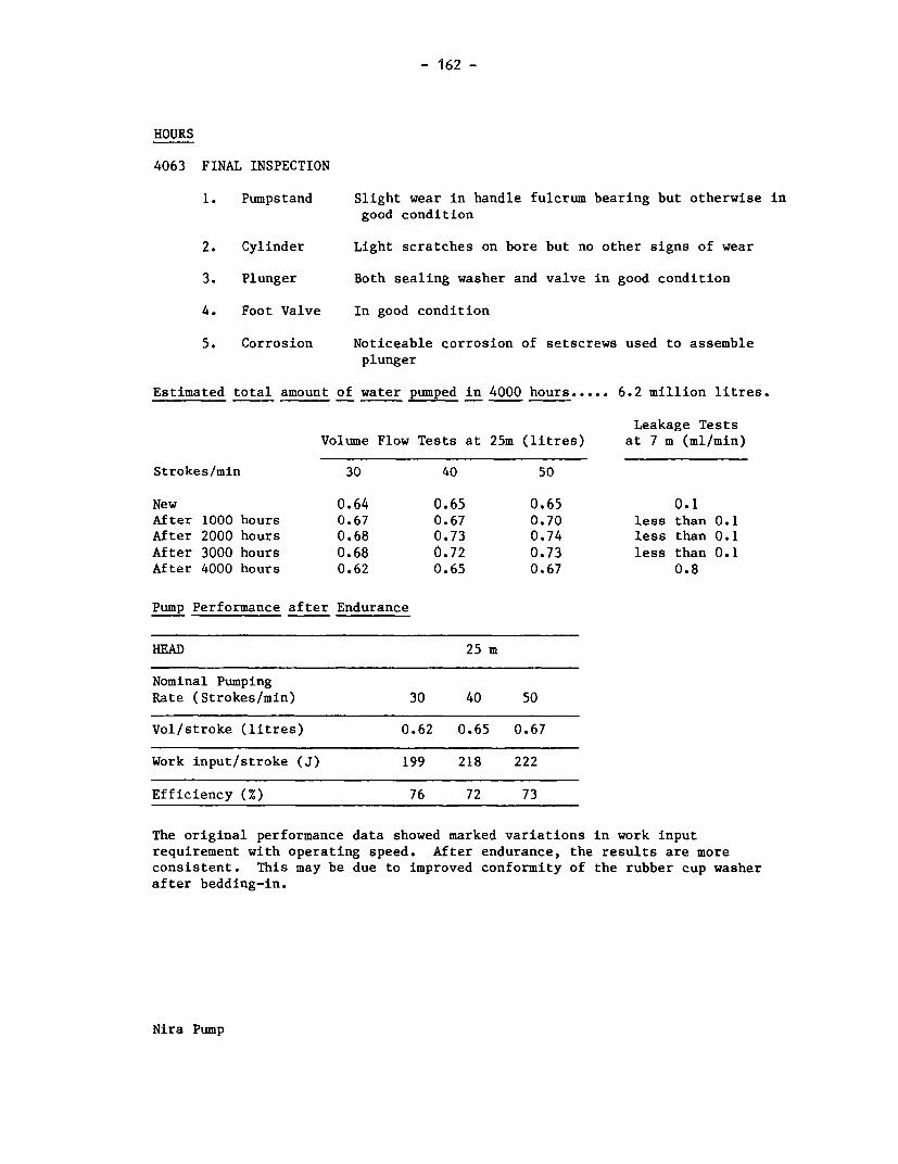
- 162 -
HOURS
4063 FINAL INSPECTION
1. Pumpstand Slight wear in handle fulcrum bearing but otherwise ingood condition
2. Cylinder Light scratches on bore but no other signs of wear
3. Plunger Both sealing washer and valve in good condition
4. Foot Valve In good condition
5. Corrosion Noticeable corrosion of setscrews used to assembleplunger
Estimated total amount of water pumped in 4000 hours ..... 6.2 million litres.
Leakage TestsVolume Flow Tests at 25m (litres) at 7 m (ml/min)
Strokes/min 30 40 50
New 0.64 0.65 0.65 0.1After 1000 hours 0.67 0.67 0.70 less than 0.1
After 2000 hours 0.68 0.73 0.74 less than 0.1
After 3000 hours 0.68 0.72 0.73 less than 0.1
After 4000 hours 0.62 0.65 0.67 0.8
Pump Performance after Endurance
HEAD 25 m
Nominal PumpingRate (Strokes/min) 30 40 50
Vol/stroke (litres) 0.62 0.65 0.67
Work input/stroke (J) 199 218 222
Efficiency (%) 76 72 73
The original performance data showed marked variations in work input
requirement with operating speed. After endurance, the results are more
consistent. This may be due to improved conformity of the rubber cup washer
after bedding-in.
Nira Pump

- 163 -
8. ABUSE TESTS
8.1 Side Impact Tests
In the side impact test on the handle, the pump top absorbed the impact byrotating on the screw threads on the pumpstand column. In the body test,the baseplate cracked at an impact of 400 Joules on the centre of thepumpstand. We understand that the manufacturer now supplies a fabricated,all-steel pumpstand baseplate.
8.2 Handle Shock Test
In the handle shock test, the pump was fitted with the later tubularhandle, repaired after breaking during the endurance test after 3017hours. The pump completed its allotted 96,000 cycles without failure.
9. VERDICT
The manufacturer now recommends a maximum depth of 18 metres, using a 3 inchcylinder, and supplies a smaller cylinder for greater depths. Some smalldesign changes and a thicker cylinder wall could make this a robust pump,potentially suitable for community water supply. Although the design doesnot demand highly specialised manufacturing processes, the levels of skillrequired make it unsuitable for manufacture in many developing countries.Moderately priced.
Nira Pump

- 164 -
Ethiopia Pump
I '
d~~ ~~~~~~~~~~~~~~~~~~~~~~~~~~~ I IX.
A0~~~~~~~~~_I
- 165 -
ETHIOPIA TYPE BP50
1.1 Manufacturer E.W.W.C.A.
Address UNICEF,PO Box 1169,ADDIS ABABA,Ethiopia.
1.2 Description The Ethiopia Type BP50 is a shallow-well force pump,originally developed from an IDRC design and makesextensive use of plastics below ground. For shallowwells a simple T-handle is attached to the top of thepump rod for direct action pumping. For depthsgreater than 12 metres, the pumpstand has a lever.
The pumpstand is fabricated from steel tube and plate.The rising main is 2 inch uPVC pipe, and is itself thecylinder. The maximum outside diameter of the below-ground assembly is 75 mm. The plunger has no separateseals; it is turned from high density polyethylene, andhas a simple rubber flap valve backed by a steel washer.The foot valve is similar, its housing made fromstandard pipe couplings. The rods are also uPVC waterpipe, stiffened with steel at the top. The handle iswood.
1.3 Price in 1981 $75
2. INSPECTION
2.1 Packaging The pumps arrived in a single wooden packing case. Acardboard carton within the case protected theplungers and valve assemblies. The case wasrelatively easy to manhandle.
2.2 Condition as Both samples were received in good working order.Received
2.3 Installation A technical report and engineering drawings were sentand Maintenance with the pumps; both accurately described the samples.Information The technical report was interesting, the drawings
helpful in installing the pump. It would be importanthowever, to know what literature would be generallysupplied with the pump.
Ethiopia Pump

- 166 -
3. WEIGHTS and MEASURES
3.1 Weights Pumpstand 11.3 kgPump rods 0.4 kg per metreRising main 1.4 kg per metre
3.2 Dimensions Nominal cylinder bore: 50 mm - 2 inch rising mainused as cylinder
Actual pump stroke: 370 mmNominal volume per stroke: 726 mlDrop pipe size: 2 inchesOutside diameter of below-ground assembly: 75 mm
Pump rod diameter: 22 mm - 0.5 inch bore PVCwater pipe
3.3 Cylinder Bore These pumps were not supplied with a cylinder; theplunger is designed to be used directly on the bore ofthe 2 inch PVC rising main. The pipe used for testingwas very smooth on the exterior but the bore waswavey. The surface roughness average (Ra)measurements were approximately 1.50 um at a cut-offof 2.5 mm, 0.60 um at a cut-off of 0.80 mm. This qualityof finish provided adequate performance but a smootherfinish will improve performance.
3.4 Ergonomic Measurements
HANDLE HEIGHT PLATFORM VELOCITY HEIGHTHEIGHT RATIO OF OF SPOUT
MAX( 1' MIN"1 (mm) of HANDLE (mm)
(mm) (mm)
1070 700 0 1:1 310
(1) Measured without compressing bump stops
4. ENGINEERING ASSESSMENT
4.1 Materials of Construction
COMPONENT MATERIAL(S)
Pumpstand Steel tube - fabricatedHandle WoodPump rod support Mild steelPump rod bush HD polyethylenePlunger HD polyethylene, rubber valveFoot valve body Fabricated from standard steel
pipe fittingsFoot valve HD polyethylene, rubber washerPump rod PVC pipe
Ethiopia Pump

- 167 -
4.2 Manufacturing Techniques
The manufacturing techniques required to make the pump are listed below:-
Above-ground Steel fabricationAssembly Basic machining
Woodwork
The pumpstand requires basic skills and is therefore particularly suitable formanufacture in a devloping country.
Below-ground uPVC fabricationAssembly Basic machining
Rubber crafting
Like the pumpstand, the plunger and footvalve demand only basic manufacturingskills.
4.3 Ease of Installation, Maintenance and Repair
4.3.1 Ease of Installation
This pump is light and easy to handle; the main requirement for skill is inmaking satisfactory joints in uPVC pipe.
4.3.2 Ease of Pumpstand Maintenance and Repair
Very straightforward. The most likely maintenance requirement will bereplacement of the top bush, and this is easy.
4.3.3 Ease of Below-ground Maintenance and Repair
The plunger may be removed very easily; only the top bush in the pumpstandneed be removed. Care will be needed in handling the pump rods however, andit may be prudent to have sockets and solvent cement on hand to repairaccidental breaks. The length of the pump rods may require frequentalteration to compensate for wear in the rising main. Lifting tackle wouldnot be needed to extract the rising main.
Ethiopia Pump

- 168 -
4.4 Resistance to Contamination and Abuse
4.4.1 Resistance to Contamination
Generally good; the spout could be easily modified to prevent possible faecal
contamination.
4.4.2 Likely Resistance to Abuse
The handle may be susceptible to impact if left raised; the spout is ratherlong; there are no locking fixings on handle clamp; the baseplate is thin.
4.5 Potential Safety Hazards
There is a potential finger trap between the handle and the top of the
pumpstand, but this is not a major hazard since the handle of this pump offers
no mechanical advantage.
4.6 Suggested Design Improvements
The handle should be more securely attached to the pump rod. This might beachieved by using a single bolt, slightly off-centre, locating in a groove cutin the pump rod.
The baseplate should be stiffer.
5. PUMP PERFORMANCE
5.1 Volume Flow, Work Input and Efficiency
The description of the method can be found in the Test Procedure
HEAD 7 m
Nominal pumpingrate (strokes/min) 30 40 50
Vol/stroke (litres) 0.60 0.62 0.63
Work Input/stroke (J) 112 117 141
Efficiency (%) 36 35 30
5.2 Leakage Tests
Leakage at 7m head was 0.15 ml/minute.
Ethiopia Pump

- 169 -
6. USER TRIAL
6.1 User Responses
Details of the organisation of this trial can be found in the Test Procedure,and the statistical analysis of user responses is presented in Appendix I.
6.2 Observations
Many users found it difficult to operate, especially short children. Most ofthe effort had to be supplied by the arms and shoulders only. Several smallerchildren found the handle difficult to lift, and changed their grip betweenup- and down-strokes. Some could lift the handle only by sliding theirforearms beneath it until it rested in the crook of their elbows, then archingtheir backs. This was a very awkward movement and resulted in very shortstrokes. Users with such difficulties tended to make matters worse by pullingunevenly on the two sides of the handle, increasing the friction in the bushat the top of the pumpstand.
7. ENDURANCE
A detailed description of the endurance test method can be found in the TestProcedure.
General Comments
The pump was tested at 40 strokes per minute at 7 metres head. It completedthe 4000 hour endurance test without failure. Wear in the plunger tended toincrease the end float of the centre bolt, and remedial action was taken atthe 1000 hour intermediate inspections. The intermediate check tests ofvolume flow also revealed progressive loss of cylinder performance, with themost pronounced loss during the fourth 1000 hour stage, when sand wasintroduced to the water.
In the final inspection, most parts of the plunger were clearly worn,particularly those parts forming the valve. Although still operating, theperformance had fallen off considerably. The piston diameter had worn by0.3mm or so, and the cylinder by about lmm on diameter. Particles of sandwere embedded in the HDPE plunger. In actual use the wear in the rising maincould be compensated by altering the position of the plunger in the risingmain. The pump rod bush in the pumpstand was worn, but this did not affectthe performance.
Hours: 1024 2037 3140 4147
Inspection Inspection Inspection Inspection Inspectionand full and volume and volume and volume and fullperformance flow flow flow performancetest test
Ethiopia Pump

- 170 -
Details of the Endurance Test
HOURS
1024 INSPECTION after 1st 1000 hours:
(a) Some wear in swept region of drop pipe - plunger still tight inremainder of drop pipe
(b) Some corrosion of nuts and bolts in both plunger and foot valve
2037 INSPECTION after 2nd 1000 hours:
(a) Top bush slightly worn(b) Plunger worn where connecting bolt fits - washer added to reduce end
float(c) More corrosion of nuts and bolts
3140 INSPECTION after 3rd 1000 hours:
(a) Top bush worn(b) Increased end float on plunger bolt(c) Plunger tight in unswept areas of rising main - some wear of rising
main in swept area(d) More corrosion of ferrous parts
4147 FINAL INSPECTION
1. Pumpstand Top bush worn but otherwise in good condition
2. Rising Main Bore worn approximately 1 mm on diameter throughoutswept area - many scratches from sand particlesembedded in plunger
3. Plunger (a) Worn approximately 0.3 mm on diameter(b) Many sand particles embedded in plunger(c) Plunger valve washer, sleeve and centre bolt all
bady worn(d) Bolt hole through plunger noticeably worn
4. Check Valve Hole in steel washer worn, but serviceable
5. Corrosion Noticeable corrosion of ferrous parts in both plungerand foot valve.
Estimated total amount of water pumped in 4000 hours ...... 5.9 million litres.
Ethiopia Pump
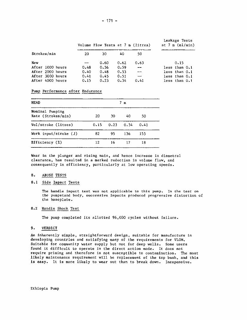
- 171 -
Leakage TestsVolume Flow Tests at 7 m (litres) at 7 m (ml/min)
Strokes/min 20 30 40 50
New -- 0.60 0.62 0.63 0.15
After 1000 hours 0.48 0.56 0.59 -- less than 0.1After 2000 hours 0.40 0.48 0.53 -- less than 0.1After 3000 hours 0.41 0.45 0.51 -- less than 0.1After 4000 hours 0.15 0.23 0.34 0.41 less than 0.1
Pump Performance after Endurance
HEAD 7 m
Nominal PumpingRate (Strokes/min) 20 30 40 50
Vol/stroke (litres) 0.15 0.23 0.34 0.41
Work input/stroke (J) 82 95 136 155
Efficiency (%) 12 16 17 18
Wear in the plunger and rising main, and hence increase in diametralclearance, has resulted in a marked reduction in volume flow, andconsequently in efficiency, particularly at low operating speeds.
8. ABUSE TESTS
8.1 Side Impact Tests
The handle impact test was not applicable to this pump. In the test onthe pumpstand body, successive impacts produced progressive distortion ofthe baseplate.
8.2 Handle Shock Test
The pump completed its allotted 96,000 cycles without failure.
9. VERDICT
An inherently simple, straightforward design, suitable for manufacture indeveloping countries and satisfying many of the requirements for VLOM.Suitable for community water supply but not for deep wells. Some usersfound it difficult to operate in the direct action mode. It does notrequire priming and therefore is not susceptible to contamination. The mostlikely maintenance requirement will be replacement of the top bush, and thisis easy. It is more likely to wear out than to break down. Inexpensive.
Ethiopia Pump

0
gg R -- ~ )r-
0
dwnd M3A
- Z.tL -

- 173 -
VEW A 18
1.1 Manufacturer Vereinigte Edelstahlwerke AG
Address Franz Josefs-Kai 51,A-1011 VIENNA,PO Box 56,Austria.
1.2 Description The VEW A 18, made in Austria, is a reciprocating, deep-well force pump, with a rotary operating mechanism. Thepump uses a cable rather than rods. The pumpstand isfabricated from stainless steel plate, with ball racesfor the crank pin and journals. As delivered, the topof the cable was attached to a saddle with the outer
ring of two ball races running in a track in the crankpin. The handle counterweights were originallyfitted on separate arms, at 900 to the handlesthemselves. The twin handles make the pump suitablefor operation by two people, and two spouts areprovided.
The heavy cylinder can be withdrawn through the 4 inchrising main and snap fits in a fixture at the bottom ofthe rising main. The maximum outside diameter of thebelow-ground assembly is 127 mm. The plunger seal isPTFE, backed by a concealed rubber 0-ring. The plungerand foot valves use stainless steel balls.
1.3 Price in 1982 $1583 - supplied complete for 20 m depth
2. INSPECTION
2.1 Packaging The pumps were delivered in a single wooden packingcase, which was robust but awkwardly long - 4 m.There were internal reinforcements to secure thecontents. It would be difficult to handle withoutmechanical assistance. All the below-groundcomponents were wrapped in a strong waxed protectivefabric.
2.2 Condition as The pumps were generally in good condition as received,Received though the handles of both pumps had been slightly
misaligned in assembly.
2.3 Installation and Maintenance Information
Useful information supplied, but further illustrations would be advantageous.
VEW Pump
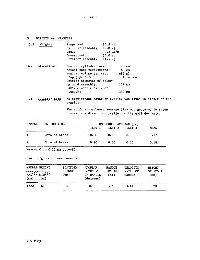
- 174 -
3. WEIGHTS and MEASURES
3.1 Weights Pumpstand 84.8 kgCylinder assembly 19.8 kgCable 0.2 kg/mCounterweight 14.0 kgStrainer assembly 11.5 kg
3.2 Dimensions Nominal cylinder bore: 70 mmActual pump revolutions: 180 mmNominal volume per rev: 693 mlDrop pipe size: 4 inchesOutside diameter of below-ground assembly: 127 mm
Maximum usable cylinderlength: 390 mm
3.3 Cylinder Bore No significant taper or ovality was found in either of thesamples.
The surface roughness average (Ra) was measured in threeplaces in a direction parallel to the cylinder axis.
SAMPLE CYLINDER BORE ROUGHNESS AVERAGE (pm)TEST 1 TEST 2 TEST 3 MEAN
1 Chromed brass 0.30 0.10 0.10 0.17
2 Chromed brass 0.20 0.20 0.15 0.18
Measured at 0.25 mm cut-off
3.4 Ergonomic Measurements
HANDLE HEIGHT PLATFORM ANGULAR HANDLE VELOCITY HEIGHTHEIGHT MOVEMENT LENGTH RATIO OF OF SPOUT
MAX(1 ) MINM1) (mm) OF HANDLE (mm) HANDLE (mm)(mm) (mm) (degrees)
1220 610 0 360 305 3.4:1 620
VEW Pump

- 175 -
4. ENGINEERING ASSESSMENT
4.1 Materials of Construction
COMPONENT MATERIAL(S)
Pumpstand Stainless steelHandle Mild steelBearings Proprietary ball racesCrankshaft Mild steelConnecting link Mild steelCylinder Extruded brass with hard chrome liningCylinder end fittings Stainless steelFoot valve Stainless steelDip tube Stainless steelPlunger assembly Stainless steel body, brass rod,
PTFE sealCable and counterweight Stainless steel
4.2 Manufacturing Techniques
The manufacturing techniques required to make the pump are listed below:-
Above-ground Steel fabrication (including stainless steel)Assembly Presswork
MachiningFlame cutting
The pumpstand demands considerable skill in manipulating and welding stainlesssteel, and heavy equipment to deal with the generous material sections.
Below-ground MachiningAssembly Hard chrome plating
Plastic moulding
The below-ground assembly demands machining to close tolerances, andconsiderable quantities of stainless steel bar stock. Some sophisticatedmanufacturing technologies and strict quality control would be essential.
4.3 Ease of Installation, Maintenance and Repair
4.3.1 Ease of Installation
7W$$4+ t*Heavy lifting tackle will be essential to handle the 4 inch rising main, andcould not readily be substituted by extra manpower. A cable-cutting tool willbe needed. The pipe wrenches must be large enough to cope with 4 inch pipe.The base of the pumpstand is threaded 4 inch API and not to the more commonISO Standard pipe thread.
VEW Pump

- 176 -
4.3.2 Ease of Pumpstand Maintenance and Repair
In its modified form, the pumpstand is unlikely to demand frequent attention.
The crankshaft assembly must be replaced as a unit, however. The pumpstandneed not be removed from the wellhead.
4.3.3 Ease of Below-ground Maintenance and Repair
The cylinder may require replacement of the plunger seal. Until recently, themanufacturer did not recommend this to be carried out on site. Replacement ofthe complete cylinder was preferred. However, we have been advised that the
cylinder is now easier to dismantle in the field. The cylinder assembly can beextracted without removing the rising main, using the operating cable. The
cylinder is heavy, but it may be possible to improvise the crankshaft assemblyas a simple lifting tackle. If the cable breaks, it may be difficult to extractthe cylinder.
4.4 Resistance to Contamination and Abuse
4.4.1 Resistance to Contamination
The short horizontal spouts would be easily contaminated. The base of thepump is sealed against surface water.
4.4.3 Likely Resistance to Abuse
No locking on any nuts or bolts. Handles quite easy to remove. Otherwisevery robust.
4.5 Potential Safety Hazards
The newer design of handles has reduced the safety hazard from the rotatingcounterweights. However, the rotating handles on this pump could be hazardousto both users and bystanders. The handles have high momentum at normaloperating speeds.
VEW Pump

- 177 -
4.6 Suggested Design Improvements
The manufacturer has adopted a number of suggestions, including the following:
(a) Changing the crankshaft plummer blocks to a heavier patternand redesigning the crankshaft 'big end' assembly.
(b) Changing the cable to the type designed for hoists and lifts,which will not twist under tension.
(c) Supplying polished solid handles.
(d) Attaching the handles more securely to the ends of the crankshaftand repositioning the counterweights.
(e) Making the cylinder easier to dismantle, to replace the plunger seals.
(f) Single rigid spout, with slots to prevent faecal contamination.
5. PUMP PERFORMANCE
5.1 Volume Flow, Work Input and Efficiency
The description of the method can be found in the Test Procedure.
HEAD 7 m 25 m 45 m
Nominal pumpingrate (revs/min) 30 40 50 30 40 50 30 40 50
Vol/rev (litres) 0.68 0.68 0.69 0.65 0.65 0.66 0.62 0.63 0.64
Work input/rev (J) 121 93 87 280 266 339 429 456 765
Efficiency (%) 38 49 53 56 59 47 63 60 36
5.2 Leakage Tests
7 m 25 m 45 m
Leakage rate (ml/min) 0.1 less than 0.1 less than 0.1
6. USER TRIAL
6.1 User Responses
Details of the organisation of this trial can be found in the TestProcedure, and the statistical analysis of user responses is presented inAppendix I.
VEW Pump

- 178 -
6.2 Observations
Users found this pump difficult to operate. Users with enough strength andbodyweight could attain sufficient momentum to keep the handle turning
smoothly. Most could not, and found it difficult to time their efforts onthe handle. Several children could not operate the pump at all. However, it
should be noted that this pump lends itself to operation by two people.Our testing staff have found the pump easier to operate with the modified
handles and re-positioned counterweights.
7. ENDURANCE
A detailed description of the endurance test method can be found in theTest Procedure.
General Comments
The pump was tested at 40 revolutions per minute at a simulated head of 45
metres and failed after only 152 hours. The tendency of the operating cableto twist under tension had made the bearing saddle run out of true, causingrapid wear of the saddle and the crankshaft. Both were replaced, and aswivel was fitted in the cable. The handle broke at 277 hours, and thereplacement bearing saddle and crankshaft were worn out after 598 hours.
The response from the manufacturer was commendably quick and the modificationshave been noted earlier. The modified handles and crankshaft big endcompleted the test programme without failure.
In the final inspection, the plunger seal was found to be worn out, theplunger body was worn and also the plunger rod where it passed through thecylinder top. The cylinder bore was in good condition. There was some play in
the big end but in all other respects the pumpstand was in good condition.
Breakdown Incidence
Breakdowns are shown in bold type.
Hours: 1024 2037 3062 4082152 598 1091 1945l
2771 l
Handle Cable llBroken| Broken lI I Cylinder
Crank Crank JammedWorn Worn l
lOut Out
Inspection Inspection Inspection Inspection Inspectionand full and volume and volume and volume and fullperformance flow flow flow performancetest test
VEW Pump

- 179 -
Details of the Endurance Test
Breakdowns are shown in bold type.
HOURS
61 Bearing saddle running out of true, caused by tendency of cable to twistunder tension. Ends of bearing axle pins worn - one split pin and washerreplaced.
152 Pronounced misalignment of bearing saddle, severe wear with imminentdanger of catastrophic failure. Crankshaft and bearing saddle replaced,swivel fitted between bearing saddle and cable.
Estimated amount of water pumped to breakdown ....... 0 .2 million litres
277 Handle broken at weld
Estimated additional amount of water pumped to breakdown ........ 0 .2 million litres
598 Crank pin severely worn, bearing track much too deep. Bearing saddlereplaced by nylon block to continue testing
Estimated additional amount of water pumped to breakdown ....... 0 .5 million litres
1024 INSPECTION after 1st 1000 hours:
(a) Plunger rod worn against cylinder top(b) Plunger seal worn(c) Some corrosion of cylinder anchor otherwise no significant corrosion
Pump rebuilt with new non-twisting cable and modified parts frommanufacturer
1091 Cable broken below head simulation valve - replaced with rod (no sparecable available)
Estimated additional amount of water pumped to breakdown ....... 0 .7 million litres
1945 Plunger jammed at top dead centre - released by pulling cable by hand
Estimated additional amount of water pumped to breakdown ....... 1.2 million litres
VEW Pump

- 180 -
HOURS
2037 INSPECTION after 2nd 1000 hours:
(a) Plunger rod worn against cylinder top
(b) Cylinder bore slightly scored(c) Some wear of plunger seal(d) Some rust at end of cable and cylinder anchor
3062 INSPECTION after 3rd 1000 hours:
(a) Plunger rod continuing to wear against cylinder top
(b) Plunger seal slightly scratched(c) Kieselguhr has accumulated around the base of the cylinder, where
the cylinder snaps into the fitting at the upper end of the dip
tube. Similar deposits in real installations may make it difficult
to reinstall a cylinder after removal(d) Noticeable rust inside rising main and on cylinder snap fitting
4082 FINAL INSPECTION
1. Pumpstand Some play in crankshaft big end bearing, otherwise ingood condition
2. Cylinder (a) Some light scratches on cylinder bore, otherwiseno signs of wear
(b) Small quantity of sand around cylinder snap
fitting
3. Plunger (a) Plunger seal circumference worn down excessively
(b) Scratches and more extensive signs of wear on
plunger body(c) Plunger rod worn against cylinder end fitting
4. Foot Valve In good condition
4082 5. Corrosion Rust around cylinder snap fitting - no other corrosion
Estimated total amount of water pumped in 4000 hours ...... 6.0 million litres.
Leakage Tests
Volume Flow Tests at 45m (litres) at 7 m (ml/min)
Revs/min 20 30 40 50
New -- 0.62 0.63 0.64 0.1
After 1000 hours 0.23 0.33 0.44 0.51 0.8
After 2000 hours 0.49 0.55 0.58 0.60 0.7
After 3000 hours -- 0.60 0.62 0.62 less than 0.1
After 4000 hours 0.31 0.42 -- 0.54 less than 0.1
VEW Pump

- 181 -
Pump Performance after Endurance
HEAD 7 m 25 m 45 m
Nominal PumpingRate (revs/min) 30 40 50 20 30 40 50 20 30 50
Vol/rev (litres) 0.59 0.60 0.61 0.42 0.49 0.53 0.56 0.31 0.42 0.54
Work input/rev (J) 192 191 190 223 224 247 236 317 327 337
Efficiency (%) 21 21 22 46 53 53 57 43 56 71
N.B. It was difficult to control the operating speeds accurately within 9revolutions of the handle due to the inertia of the counter-weights. Theactual operating speeds have been rounded to the nearest 10 revs/minute.
These results cannot be compared with the original performance data, becausethe plunger seal was replaced during the endurance test.
8. ABUSE TESTS
8.1 Side Impact Tests
The test on the handle was not applicable to this pump. The pumpsustained no damage in the side impact test on the body of the pumpstand.
9. VERDICT
Very expensive. Robust as modified by the manufacturer. Awkward to use, butdesigned to be operated by two people. Not suitable for manufacture indeveloping countries. Needs very heavy lifting tackle for installation, butcylinder may be withdrawn for maintenance on end of cable, possibly usingcrankshaft as windlass. Not suitable for boreholes of less than 130 mmdiameter. Suitable for community water supply where the necessarymaintenance skills and facilities are available.
VEW Pump

- 182 -
Jetmatic Pump
II
;~~~~~~~~~
03QI t;z;ng

- 183 -
JETMATIC
1.1 Manufacturer Sea Commercial Company Inc.
Address 3085 R. Magsaysay Blvd.,Cor. V.Cruz St.,MANILA 2806,Philippines.
1.2 Description The Jetmatic pump is made in the Philippines, underlicence from Kawamoto Pumps of Japan, and is verysimilar to the Dragon pump. Like the Dragon, it canbe supplied either as a shallow-well suction pump oras a deep-well force pump. We have tested the pumpin its deep-well configuration. Unlike the Dragon,the shallow-well cylinder is not retained. Thepumpstand is therefore very compact, and simply fitson the protruding end of the rising main which mustbe at least 440 mm above ground, to prevent thehandle touching the ground at the lowest point ofits travel.
The pumpstand is principally cast iron, with adischarge valve in the spout allowing either freedischarge or delivery under pressure through a hoseor pipe. The tubular steel handle moves through anunusually wide arc of 1780.
The deep-well cylinder is unusually small, only 46mm bore, to fit inside 2 inch rising main, which isvery much smaller than the cylinder used in theDragon pump. At the lower end of the cylinder aretwo steel loops which appear to be designed to gripthe inside of the rising main. Turning the cylinderclockwise then expands a rubber ring which anchorsand seals the cylinder against the inside of therising main. The foot valve has a tapered rubberring which fits a machined taper in the base of thecylinder. The plunger can be screwed onto the footvalve to remove it, without removing the cylinder.In other respects the plunger is conventional, andhas two leather cup seals.
1.3 Price in 1982 $32 without connecting rod and rising main
2. INSPECTION
2.1 Packaging The pumps arrived in a wooden packing case, withinternal reinforcements to separate and secure thecontents. The case was lined with moistureproofplastic membrane.
Jetmatic Pump

- 184 -
2.2 Condition as In both sample cylinders, the cup seal retainersReceived were not tight, possibly because the leather had
dried out and shrunk in transit. Otherwise the pumps
were in good working order.
2.3 Installation & Maintenance Information None supplied with the pump.
3. WEIGHTS and MEASURES
3.1 Weights Pumpstand 16.3 kgCylinder assembly 3.0 kgPump rods 1.1 kg per metre
3.2 Dimensions Nominal cylinder bore: 46 mmActual pump stroke: 175 mmNominal volume per stroke 291 mlDrop pipe size: 2 inchesOutside diameter of below-ground assembly: 74 mmPump rod diameter: 0.5 inchesMaximum usable cylinderlength: 553 mm
3.3 Cylinder Bore No significant taper or ovality was found in either of the
samples.
The surface roughness average (Ra) was measured in threeplaces in a direction parallel to the cylinder axis.
SAMPLE CYLINDER BORE ROUGHNESS AVERAGE (um)TEST 1 TEST 2 TEST 3 MEAN
1 Extruded brass 0.03 0.04 0.02 0.03
2 Extruded brass 0.04 0.04 0.05 0.04
Measured at 0.25 mm cut-off
3.4 Ergonomic Measurements
HANDLE HEIGHT PLATFORM ANGULAR HANDLE VELOCITY HEIGHTHEIGHT MOVEMENT LENGTH RATIO OF OF SPOUT
MAX()1 MIN" 1 ) (mm) OF HANDLE (mm) HANDLE (mm)
(mm) (mm) (degrees)
1410 120 554 (2) 174 660 7.8:1 505
(1) Measured without compressing bump stops(2) Height of protruding rising main
Jetmatic Pump

- 185 -
4. ENGINEERING ASSESSMENT
4.1 Materials of Construction
COMPONENT MATERIAL(S)
Pump head Cast ironHandle fork and link Cast ironBearings Mild steel pivot pins bear on holes
drilled and reamed in iron castingsSpout assembly Cast iron with rubber valveOperating rod Mild steelHandle Steel tube, rubber end capCylinder Extruded brassPlunger Cast gunmetal or bronzeCup seals LeatherFoot valve assembly Bronze housing, rubber clamp
steel guard
4.2 Manufacturing Techniques
The manufacturing techniques required to make the pump are listed below:-
Above-ground Iron foundryAssembly Brass/gunmetal foundry
Basic machiningRubber moulding
The pumpstand requires a moderate level of foundry skill, and the ability tocarry out simple machining. The handle linkage demands careful manufacturingquality control to ensure easy assembly and satisfactory operation. It may besuitable for manufacture in some developing countries, but is not ideal.
Below-ground Brass/gunmetal foundryAssembly Steel fabrication
Basic machiningRubber mouldingLeather craft
The below-ground components demand similar levels of manufacturing skill tothose required in the pumpstand.
Jetmatic Pump

- 186 -
4.3 Ease of Installation, Maintenance and Repair
4.3.1 Ease of Installation
0tThe rising main must be secure in the wellhead, to support the pumpstand. Itshould protrude sufficiently to allow clearance under the spout for the tallestvessel likely to be used. Installing the pumpstand only on an existing rising
main would be a simple, one-man task. The rising main should be 2 inchdiameter, to allow the cylinder to pass through for maintenance. The bottom of
the pumpstand is threaded 1.25 ANPT not the more common ISO Standard pipethread.
4.3.2 Ease of Pumpstand Maintenance and Repair
The pumpstand may require frequent attention to worn handle components and thegland nut.
4.3.3 Ease of Below-ground Maintenance and Repair
The foot valve and plunger may be extracted through the rising main, providedpipe of at least 2 inch diameter is used, and lifting tackle would not berequired. The pumpstand must first be removed, however.
4.4 Resistance to Contamination and Abuse
4.4.1 Resistance to Contamination
Good sealing at top of pump but rising main must be sealed at wellhead.
4.4.2 Likely Resistance to Abuse
Handle fork strong. Cast iron hose connector may be susceptible to damage.Potentially weak pumphead mounting supported only by 1.25 inch rising main.
4.5 Potential Safety Hazards
The end of the tubular steel handle is sharp and could be dangerous if theeasily removed rubber cap were lost. The handle fulcrum pinch bolt forms a
finger trap.
Jetmatic Pump

- 187 -
4.6 Suggested Design Improvements
The free end of the handle should be belled out and smoothed and the rubber endcap omitted.
The wishbone link may be easier to manufacture in a developing country as twojoggled steel strips.
The handle fulcrum pinch bolt should be moved 900 to the underside, orreplaced by two circlips on the shaft, similar to those on the wishbone linkpivots.
The height of the top housing should be reduced to:
(a) eliminate the counterbore in the gland nut(b) eliminate unnecessary machining of the pivot casting(c) increase the length of thread attaching the connecting rod to the
pivot casting.
The discharge valve should be removed as a cost-saving and only supplied ifneeded.
All pump body flanges should be flat or increased in thickness as they areunsupported and can be broken by over-tightening the fixing bolts.
The lift of both plunger and foot valves should be much reduced, ideally to onequarter of the effective diameter.
The manufacturer has ackpowledged these suggestions and his detailed commentsare awaited.
As a 2 inch rising main is necessary to allow the cylinder to pass through formaintenance, the diameter of the bottom of the pumpstand should be modified to2 inch ISO Standard pipe thread.
5. PUMP PERFORMANCE
5.1 Volume Flow, Work Input and Efficiency
The description of the method can be found in the Test Procedure.
HEAD 7 m 25 m 45 m
Nominal pumpingrate (strokes/min) 30 40 50 30 40 50 30 40 50
Vol/stroke (litres) 0.29 0.29 0.29 0.28 0.27 0.29 0.28 0.28 0.28
Work input/stroke (J) 60 54 50 110 103 107 173 173 161
Efficiency (%) 32 36 39 62 63 66 71 72 77
Jetmatic Pump

- 188 -
5.2 Leakage Tests
HEAD 7 m 25 m 45 m
Leakage rate (ml/min) 0.1 less than 0.1 less than 0.1
6. USER TRIAL
6.1 User Responses
Details of the organisation of this trial can be found in the TestProcedure, and the statistical analysis of user responses is presented inAppendix I.
6.2 Observations
This pump is similar to the Dragon pump, and users had similar problems. Anadditional difficulty arose because vigorous operation of the pump oftencaused the outlet discharge valve to drop, shutting off the spout which mayblow the gaskets. The rate of delivery was considered to be poor.
7. ENDURANCE
A detailed description of the test method can be found in the TestProcedure.
General Comments
The pump was tested at 40 strokes per minute at a simulated head of 45 metresand failed at 280 hours when the cylinder was dislodged within the rising main.It was refitted and the problem did not recur. The pump failed at 3149 and3875 hours when the pump rod broke within the thread. Components of thehandle mechanism had to be replaced after 1000 hours because of wear, thoughthe replacement parts survived until the end of the 4000 hour test programme.At each intermediate inspection, the spout discharge valve was found to beseized through lack of use, and it was freed off.
In the final inspection, the foot valve, plunger, leather cup seals and cylinderwere all in good condition, with few signs of wear. The gland nut was badlyworn. The plunger rod and the steel loops on the cylinder anchor werecorroded and may not have been satisfactory if used again.
Jetmatic Pump

- 189 -
Breakdown Incidence
Breakdowns are shown in bold type.
Hours: 1024 2037 3140 4144
280 3149 3875 I
Cylinder Handle Pump Pump II Dislodged Parts Rod Rod| Worn Out Broken Broken I
Inspection Inspection Inspection Inspection Inspectionand full and volume and volume and volume and fullperformance flow flow flow performancetest test
Details of the Endurance Test
Breakdowns are shown in bold type.
HOURS
280 Cylinder dislodged in casing - repositioned
Estimated amount of water pumped to breakdown ...... 0.2 million litres
1024 INSPECTION after 1st 1000 hours:
(a) Handle link bearings and pin badly worn - replaced(b) Some deterioration of rubber retaining ring at bottom of cylinder(c) Plunger seals hard and tight in cylinder(d) Pump rod gland worn(e) Some corrosion at joint of pump rod and plunger
Estimated additional amount of water pumped to breakdown ....... 0 .5 million litres
2037 INSPECTION after 2nd 1000 hours:
(a) Handle fulcrum showing signs of wear(b) Further wear in pump rod gland(c) Pump rod corroded, particularly at joint with plunger
3140 INSPECTION after 3rd 1000 hours:
(a) Kieselguhr packed tight between cylinder and rising main makingcylinder difficult to remove
(b) Further wear in pump rod gland(c) Pump rod further corroded, particularly at joint with plunger
Jetmatic Pump

- 190 -
HOURS
3149 Pump rod broken within thread at uppermost joint - new section fitted
Estimated additional amount of water pumped to breakdown ....... 1.4 million litres
3875 Connecting rod broken within thread at joint with pump rod - replacedwith spare part from manufacturer.
Estimated additional amount of water pumped to breakdown ....... 0.5 million litres
4144 FINAL INSPECTION
1. Pumpstand (a) Gland worn(b) Slight wear in pivot pins and bushes
2. Cylinder (a) Some sand between cylinder and rising main butcylinder not difficult to remove
(b) Slight scratching of bore, but cylinder in goodcondition
3. Plunger Generally in good condition
4. Foot Valve Generally in good condition
5. Corrosion (a) Considerable rusting of plunger rod(b) Rust on steel loops of cylinder retainer
Estimated total amount of water pumped in 4000 hours ...... 2.7 million litres.
Leakage TestsVolume Flow Tests at 45m (litres) at 7 m (ml/min)
Strokes/min 20 30 40 50
New -- 0.28 0.28 0.28 0.1
After 1000 hours 0.25 0.25 0.25 -- 0.2
After 2000 hours 0.23 0.25 0.25 -- 0.1
After 3000 hours 0.26 0.26 0.26 -- less than 0.1After 4000 hours 0.29 0.29 0.29 -- less than 0.1
Jetmatic Pump

- 191 -
Pump Performance after Endurance
HEAD 7 m 25 m 45 m
Nominal PumpingRate (Strokes/min) 20 30 40 20 30 40 20 30 40
Vol/stroke (litres) 0.29 0.30 0.29 0.29 0.29 0.29 0.29 0.29 0.29
Work input/stroke (J) 47 46 44 96 95 91 149 142 139
Efficiency (%) 42 44 45 75 75 78 84 89 91
If compared with the original performance data, these results show aconsistent reduction in the work input requirement, and consequentlyimprovements in efficiency, this suggests that bedding-in of the headbearings has reduced the frictional losses.
8. ABUSE TESTS
8.1 Side Impact Tests
In the side impact test on the handle, the impact energy was absorbed bythe pumpstand turning on its mounting thread. In the body test, thesupporting rising main began to bend at an impact of 200 Joules, and at300 Joules the pipe was sufficiently bent to prevent movement of the pumprod.
8.2 Handle Shock Test
After 13,341 cycles of the handle shock test, the fixings attaching thebody of the pumpstand to the base casting had loosened, allowing thejoint to leak. The pump failed after 79,383 cycles when the thread inthe base casting was partially stripped, producing severe leakage.
9. VERDICT
The Dragon pump, from which the Jetmatic is derived, was designed for familyuse, possibly serving up to 15 people. The Jetmatic is unlikely to besufficiently robust for community water supply, from deep wells. The rate ofdelivery is low, and intensive use will produce rapid wear, failure in themoving parts of the pumpstand, and pump rod breakage. See comment on pumprod constraint on page 17. The complete cylinder can be extracted withoutremoving the rising main. Possibly suitable for manufacture in somedeveloping countries, but not an ideal design. Cheap.
Jetmatic Pump

- 192 -
Bandung Pump
_ ~~~~~I
-1 ~ ~ ~ ~ ~ ~ ~ j-
IUI0
I ~ ~ ~
- ic
(a 1

- 193 -
BANDUNG
1.1 Manufacturer Iwaco B.V.
Address: PO Box 183,3000 AD Rotterdam,The Netherlands.
1.2 Description The Bandung is a shallow-well suction pump. It is
mainly constructed of cast iron, with an enamelled steelcylinder liner. The plunger uses a moulded rubber cupwasher, and rubber discs are used as plunger and checkvalves.
1.3 Price in 1981 $54
2. INSPECTION
2.1 Packaging The packaging in which these pumps were delivered wasverv unsuitable.
Each pump was wrapped in pieces ofcorrugated cardboard and then in aplastic sack - see photograph, left.
The handles of both pumps, and a thirdspare handle, were broken in transit,and the cylinder top casting of one
-As - x i -pump was cracked.
These components were replaced by the manufacturer, whosaid that the pumps left the factory packed together ina wooden crate. They were separated by the carrier,presumably because their weight as a single consignmentwas too great.
2.2 Condition as Neither sample was received in working order,Received because of the broken handles. In addition, one
retaining bolt for the connecting rod pivot shaftwas broken, and one check valve seat was unevenlycoated with filler and paint, preventing asatisfactory seal against the rubber valve block.Even if the handles had been delivered unbroken, thepumps would still have been unusable.
2.3 Installation & Maintenance Information None supplied with pump.
Bandung Pump

- 194 -
3. WEIGHTS and MEASURES
3.1 Weights Pumpstand 25.5 kg
3.2 Dimensions Nominal cylinder bore: 96 mmActual pump stroke: 135 mmNominal volume per stroke: 977 mlDrop pipe size: 1.25 inchesMaximum usable cylinderlength 135 mm
3.3 Cylinder Bore No significant taper or ovality was found in either of thesamples.
The surface roughness average (Ra) was measured inthree places in a direction parallel to the cylinder axis.
SAMPLE CYLINDER BORE ROUGHNESS AVERAGE (ym)TEST 1 TEST 2 TEST 3 MEAN
1 Enamelled steel 0.72 0.76 0.32 0.60
2 Enamelled steel 0.18 0.40 0.40 0.33
Measured at 0.25 mm cut-off
3.4 Ergonomic Measurements
HANDLE HEIGHT PLATFORM ANGULAR HANDLE VELOCITY HEIGHT
HEIGHT MOVEMENT LENGTH RATIO OF OF SPOUT
MAX( 1 ) MINM1 ) (mm) OF HANDLE HANDLE (mm)
(mm) (mm) (degrees)
1107 465 300 69 565 5.0:1 605
(1) measured without compressing bump stops
Bandung Pump

- 195 -
4. ENGINEERING ASSESSMENT
4.1 Materials of Construction
COMPONENT MATERIAL(S)
Pumpstand Cast iron with enamelledsteel cylinder liner
Handle Cast ironBearings Mild steel pivot pins bear on holes
drilled and reamed in iron castingsPlunger Cast ironCup seal Moulded rubberBase valve Rubber with moulded plastic
cage
4.2 Manufacturing Techniques
The manufacturing techniques required to make the pump are listed below:-
Iron foundrySheet metal formingEnamelling of steelSimple machiningRubber/plastic moulding
Where adequate skills in iron foundry work, simple sheet metalwork and basicmachining are available, the Bandung may be well-suited for manufacture in adeveloping country. However, the Bandung demands stricter quality controlduring manufacture than the New No.6, which is of similar design.
4.3 Ease of Installation, Maintenance and Repair
4.3.1 Ease of Installation
Very straightforward.
4.3.2 Ease of Maintenance and Repair
The pump may require frequent attention, but most tasks are simple and couldbe accomplished with a few spanners. A drift and hammer may be needed toremove the pivot pins, however, and a pipe wrench to dismantle the plunger.
Bandung Pump

- 196 -
4.4 Resistance to Contamination and Abuse
4.4.1 Resistance to Contamination
The pump will need to be primed and is therefore susceptible to contamination.
4.4.2 Likely Resistance to Abuse
Handle and pump top susceptible to accidental damage. No lock washers on
fixings.
4.5 Potential Safety Hazards
There is a potential finger trap between the connecting rod fork and the top
of the pumpstand.
4.6 Suggested Design Improvements
The relative positions of the fork and eye in the connecting rod and handle
should be reversed - i.e. the handle should be forked, with an eye on the end
of the connecting rod.
The handle should be more robustly designed or made in a more resilient
material.
The design of the plunger should be improved to control the compression of the
cup washer, to reduce the tendency of the rubber to extrude outwards.
The webs on the cylinder top castingshould be extended to make it morerobust - see illustration.
Bandung Pump

- 197 -
5. PUMP PERFORMANCE
5.1 Volume Flow, Work Input and Efficiency
The description of the method can be found in the Test Procedure.
HEAD 7 m
Nominal pumpingrate (strokes/min) 20 30 40
Vol/stroke (litres) 0.95 0.96 1.04
Work input/stroke (J) 94 93 102
Efficiency (%) 69 70 70
5.2 Leakage Test
Leakage at 7 m head was 0.25 ml/minute
6. USER TRIAL
6.1 User Responses
Details of the organisation of this trial can be found in the Test Procedure,and the statistical analysis of the user responses is presented in Appendix I.
6.2 Observations
Few users criticised this pump, though few singled it out for praise. Thehandle movement allowed many muscle groups to contribute to operating thepump.
7. ENDURANCE
A detailed description of the endurance test method can be found in the TestProcedure.
General Comments
The pump was tested at 30 strokes per minute at 7 metres head. The cup washerwas replaced three times in the 4000 hour endurance test. The seal tended toextrude into the clearance between the plunger and the cylinder wall, and splitas a result. The two halves of the plunger were modified so that the cup washerwas nipped near its outer edge; this prevented the outward extrusion of therubber, and the last replacement cup washer did not split in over 1000 hours.However, the final inspection revealed cracks in the upper surface of the cupwasher, although it was still working.
Bandung Pump

- 198.-
The pump proved difficult to prime after the 3000 hour check, but this wascorrected by simply turning over the check valve block. Both valve blocksshowed signs of wear in the final inspection, but were in working order.
The cylinder was in good condition at the end of the test, with no signs of
wear.
The handle pivot pins, and their corresponding holes, were worn but stillserviceable at the end of the test.
Breakdown Incidence
Breakdowns are shown in bold type.
Hours: 1072 2044 3017 4063809 I 2018 l
Cup I Cup CupWasher Washerl WasherSplit Split Split
Inspection Inspection Inspection Inspection Inspectionand full and volume and volume and volume and fullperformance flow flow flow performance
test test
Details of the Endurance Test
Breakdowns are shown in bold type.
HOURS
651 Handle pivot noisy and rusty - no action
809 Cup washer split - replaced
Estimated amount of water pumped to breakdown ...... 1.4 million litres
1072 INSPECTION after 1st 1000 hours:
Some corrosion of ferrous parts
2018 Cup washer split - replaced
Estimated additional amount of water pumped to breakdown ........ 2.1 million litres
Bandung Pump

- 199 -
HOURS
2044 INSPECTION after 2nd 1000 hours:
(a) More corrosion of ferrous parts(b) Some wear of pins in handle fulcrum and connecting rod end
3017 INSPECTION after 3rd 1000 hours:
(a) Cup washer beginning to split - plunger machined to nip cup washer onouter edge when retaining nut tightened
(b) Noticeable wear in handle components(c) Noticeable wear on circumference and seat of check valve - priming
difficult - valve block turned over(d) More corrosion of ferrous parts
Estimated additional amount of water pumped to breakdown ....... 1 .7 million litres
4063 FINAL INSPECTION:
1. Pump Body and Handle (a) Cylinder bore in good condition showing nosigns of wear
(b) Fulcrum pins and bushes all worn, thoughpump still working
(c) Handle no longer contacts bottom stop(because of wear in fulcrum bearings) butfouls on connecting rod eye
2. Plunger (a) Plunger valve noticeably worn though stillserviceable
(b) Some cracks in upper surface of cup washerthough still watertight - seephotograph, below
Bandung Pump

- 200 -
HOURS
4063 3. Check Valve Signs of wear but still serviceable
4. Corrosion (a) Rust on sliding plate on pump top andassociated contact areas of pumpstand
(b) Rust in plunger valve cage(c) Rust inside pump body above cylinder
lining
Estimated total amount of water pumped in 4000 hours ....... 6.9 million litres.
Leakage TestsVolume Flow Tests at 7 m (litres) at 7 m (ml/min)
Strokes/min 20 30 40
New 0.96 0.97 1.04 0.6
After 1000 hours 1.02 1.12 1.07 0.1After 2000 hours 1.05 1.13 1.10 0.7After 3000 hours 1.11 1.11 1.04 less than 0.1After 4000 hours 1.04 1.13 1.02 less than 0.1
Pump Performance after Endurance
HEAD 7 m
Nominal pumpingrate (Strokes/min) 20 30 40
Vol/stroke (litres) 1.04 1.13 1.02
Work input/stroke (J) 109 125 137
Efficiency (%) 65 62 50
These results are not comparable with the original performance data becausethe cup washer was replaced during the endurance test.
Bandung Pump
- 201 -
8. ABUSE TESTS
8.1 Side Impact Tests
The Bandung pump failed in the side impact tests. In the test on thehandle, the pump top casting broke at an impact of 150 Joules on thehandle, though the handle itself survived. In the body test, the basecasting fragmented at an impact of 500 Joules on the centre of thepumpstand.
8.2 Handle Shock Test
In the handle shock test, the handle fulcrum extension broke away from thepump top casting after 19,543 cycles, and the test was terminated. Thehandle itself was undamaged.
9. VERDICT
The Bandung pump is susceptible to accidental damage. It requires priming andis therefore susceptible to contamination, and hence is not recommended fordrinking water supply. It could be more reliable with some design changes,to the pumpstand castings and the plunger. Cheap.
NB. It would have been helpful to have had some reaction from themanufacturer.
Bandung Pump
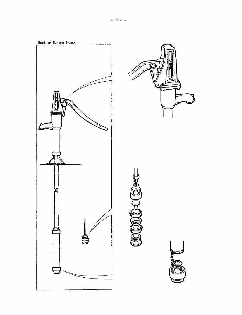
- 202 -
Suinber Banyu Pump
3'
lEJ, 1~e

- 203 -
SUMBER BANYU ("SB")
1.1 Manufacturer P.T.Celco Industrial Company, Ltd.,
Address 43A JL Jendral,Gatot Subroto,BANDUNG, Indonesia
1.2 Description This pump was a derivative deep-well design fromAID/Battelle for manufacture in developing countries.The pumps tested were made in Indonesia. The pumpstandis almost entirely cast iron, though the column is alength of steel tube threaded at each end. It featuresa crosshead mechanism to guide the top of the pump rod.
The cylinder design is conventional, except that uPVCtube is used in place of the more usual seamless brasstube, with cast iron end caps. Two leather cup sealsare used on the plunger. The foot valve is a simpleflap of leather with a cast iron weight.
1.3 Price in 1981 $85
2. INSPECTION
2.1 Packaging These pumps were delivered in a slatted woodenpacking case. The package weighed 191 kg and might beawkward to man-handle for overland transportation.
2.2 Condition as Both samples were generally in good condition asReceived received, though the cup seal retainers on both pumps
were insufficiently tight. This may have been due todrying out of the leather in transit.
2.3 Installation & Maintenance Information None supplied with the pump.
3. WEIGHTS and MEASURES
3.1 Weights Pumpstand 39.5 kgCylinder assembly 5.5 kgPump rods 0.8 kg per metre
3.2 Dimensions Nominal cylinder bore: 78 mmActual pump stroke: 180 mmNominal volume per stroke: 860 mlDrop pipe size: 1.25 inchesOutside diameter of below-ground assembly: 100 mm
Pump rod diameter: 10 mmMaximum usable cylinderlength: 303 mm
Sumber Banyu Pump

- 204 -
3.3 Cylinder Bore No significant taper or ovality was found in either of thesamples.
The surface roughness average (Ra) was measured in threeplaces in a direction parallel to the cylinder axis.
SAMPLE CYLINDER BORE ROUGHNESS AVERAGE (um)TEST 1 TEST 2 TEST 3 MEAN
1 Extruded PVC 0.70 0.60 0.80 0.70
2 Extruded PVC 0.65 0.85 0.70 0.73
Measured at 0.80 mm cut-off
3.4 Ergonomic Measurements
HANDLE HEIGHT PLATFORM ANGULAR HANDLE VELOCITY HEIGHTHEIGHT MOVEMENT LENGTH RATIO OF OF SPOUT
MAX(l) MIN" 1 ) (mm) OF HANDLE (mm) HANDLE (mm)
(mm) (mm) (degrees)
1229 250 0 91 860 5.8 500
(1) Measured without compressing bump stops.
4. ENGINEERING ASSESSMENT
4.1 Materials of Construction
COMPONENT MATERIAL(S)
Pumpstand Cast iron head, spout and base, steel columnFulcrum link Cast ironHandle Cast ironBearings Mild steel pivot shafts bear on mild steel
wrapped bushesConnecting rod Mild steelCylinder Extruded PVC, cast iron end capsPlunger assembly Gunmetal bodyCup seals LeatherFoot valve Leather with cast iron weight
The original Battelle drawings specify the pins as cold drawn mild steel but
do not specify bushes at all. A subsequent amendment by AID and GeorgiaInstitute of Technology specify the pins to be hardened to Rockwell C 40 andthe bushes to Rockwell C 60/64.
When measured the pins were found to be 140 Vickers Pyramid Number and thebushes 160 VPN, both less than the lowest number on the Rockwell C scale.
Sumber Banyu Pump

- 205 -
4.2 Manufacturing Techniques
The manufacturing techniques required to make the pump are listed below:-
Above-ground Iron foundryAssembly Basic machining
Where facilities and skills in iron foundry work and basic machining are
available, this pump may be suitable for manufacture in a developing country.However, the handle mechanism and the crosshead assembly demand careful qualitycontrol to ensure proper assembly and smooth running. In the samplessupplied, the components of the two pumps were not interchangeable, and thespares did not fit either pump. No jigs and fixtures appear to have been
used in manufacture: this is essential to ensure the interchangeability ofspares. The pivot shafts and bushes must be hardened.
Below-ground Iron foundryAssembly Brass/gunmetal foundry
Basic machiningLeather crafting
Similar levels of skill are required for the below-ground components to thoseneeded to manufacture the pumpstand.
4.3 Ease of Installation, Maintenance and Repair
4.3.1 Ease of Installation
The pumpstand may require some re-working of the various handle components toensure smooth operation.
4.3.2 Ease of Pumpstand Maintenance and Repair-,AS4The pumpstand is likely to require frequent attention to the handle, fulcrumlink and connecting rod eye, and their respective pivot pins. Most tasks are
easy, requiring spanners and pliers only, though a drift and hammer may beneeded to remove the pivot pins. Our experience suggests that replacement partsmay not be interchangeable with the original components, possibly making on-site
repair impossible.
Sumber Banyu Pump

- 206 -
4.3.3 Ease of Below-ground Maintenance and Repair
~ 4tThe cylinder is likely to require frequent attention to the foot valves and tobroken pump rod joints. Below-ground repairs require removal of the completebelow-ground assembly.
4.4 Resistance to Contamination and Abuse
4.4.1 Resistance to Contamination
The spout should be modified to prevent possible faecal contamination. The pumpis sealed against surface water but the pump could be contaminated through theconnecting rod hole.
4.4.2 Likely Resistance to Abuse
Split pins easy to remove, no locking fixings. Handle may be susceptible toimpact. Otherwise robust.
4.5 Potential Safety Hazards
There are potential finger traps between the pump top and the sliding guideblocks at the top and bottom of the handle stroke.
4.6 Suggested Design Improvements
The bearing bushes in the handle and associated links are of doubtful benefit -
the cast iron would provide a satisfactory bearing surface for the steelshafts. If the bushes are retained, both they and the associated pivot pinsshould be hardened to the original specification.
The lift of the plunger valve should be reduced, ideally to one quarter of itseffective diameter, and its location improved.
A handle made from a more resilient material would be less prone to accidentaldamage.
The foot valve should be redesigned to avoid early failure.
It is recommended that the design of the handle fulcrum be simplified, and thecrosshead mechanism eliminated.
No reaction to the above suggestions has yet been received from themanufacturer.
Sumber Banyu Pump

- 207 -
5. PUMP PERFORMANCE
5.1 Volume Flow, Work Input and Efficiency
HEAD 7 m 25 m 45 m
Nominal pumpingrate (strokes/min) 30 40 50 30 40 50 30 4C 50
Vol/stroke (litres) 0.83 0.86 0.85 0.82 0.81 0.81 0.80 0.80 0.81
Work input/stroke (J) 101 100 111 290 293 312 458 480 536
Efficiency (%) 55 58 52 69 67 63 76 73 66
5.2 Leakage Tests
HEAD 7 m 25 m 45 m
Leakage rate (ml/min) less than 0.1 0.4 2.4
6. USER TRIAL
6.1 User Responses
Details of the organisation of this trial can be found in the TestProcedure, and the statistical analysis of user responses is presented inAppendix I.
6.2 Observations
Most users seemed to operate this pump without difficulty. Many muscle groupscould be called into play without exaggerated body movements.
Sumber Banyu Pump

208 -
7. ENDURANCE
A detailed description of the endurance test method can be found in the TestProcedure.
General Comments
The pump was tested at 40 strokes per minute, initially at a simulated head of45 metres.
The pump failed several times in the endurance test, due to rapid wear oflinkages in the pumpstand, broken rods and worn-out foot valves. After fivefailures in the first 1000 hours, the simulated head was reduced to 30 metres.
The handle, fulcrum link, connecting rod eye and their associated pivot pinswore rapidly, and had to be replaced several times in 4000 hours. The pump rodbroke six times, twice in the connecting rod at the top, twice in the plungerrod, and twice in the intermediate rods. The connecting rod and plunger rod weresupplied with the pumps. The plunger rod breakages were caused by failures ofthe foot valve. In each case, the leather had rotted away allowing the castiron weight to foul the plunger.
In the final inspection, the plunger and cup seals were still in good condition,and the cylinder bore was polished but otherwise showed few signs of wear. Thecrosshead blocks and guides were worn but still serviceable. All other movingparts had been replaced at some stage during the 4000 hours. The cylinder endcaps were heavily rusted.
Breakdown Incidence
Breakdowns are shown in bold type.
Hours: 1024 2037 3123 4130248 416 989 1076 2474 4078
287 596 l
-Handle Fulcrum Pump Conn. Plunger PlungerLinks Link Rod Rod Rod RodWorn Worn Broken Broken Broken Broken
l I (foot (footConn. Conn. valve Handle valve
Rod Rod failed) Links failed)Broken Broken Worn
Inspection Inspection Inspection Inspection Inspectionand full and volume and volume and volume and fullperformance flow flow flow performancetest test
C mhavr flnni Pimr

- 209 -
Details of the Endurance Test
Breakdowns are shown in bold type.
HOURS
248 Severe wear of handle, fulcrum link and pivot pin
Estimated amount of water pumped to breakdown ....... 0 .5 million litres
287 Connecting rod broken at thread on upper end
Estimated additional amount of water pumped to breakdown ...... 0 .07 million litres
416 Fulcrum link pin worn
Estimated additional amount of water pumped to breakdown ....... 0 .2 million litres
596 Connecting rod eye, handle and pivot pin badly worn
Estimated additional amount of water pumped to breakdown ........ 0 .3 million litres
989 Pump rod broken at thread - simulated head reduced from 45 to 30 m
Estimated additional amount of water pumped to breakdown ........ 0 .8 million litres
1024 INSPECTION after 1st 1000 hours:
(a) Leather cup washers distorted(b) Some corrosion of ferrous parts
1076 Connecting rod broken at thread
Estimated additional amount of water pumped to breakdown ........ 0 .2 million litres
2037 INSPECTION after 2nd 1000 hours:
(a) Some wear in handle pins and bushes(b) Plunger valve somewhat worn on its circumference(c) More corrosion of ferrous parts
2474 Plunger rod broken at thread - foot valve leather had rotted away allowingweight to foul plunger causing rod to break. New foot valve assembly andplunger rod fitted.
Estimated additional amount of water pumped to breakdown ........ 2.7 million litres
Sumber Banyu Pump

- 210 -
HOURS
3123 INSPECTION after 3rd 1000 hours:
(a) Bushes in handle fork worn through, pin approx. 50X worn(b) Pump rod eye worn(c) Some wear in crosshead guides and blocks(d) Fulcrum link bushes worn at pump body pivot
Holes in handle fork and pump rod eye bored out but not re-bushed.Stepped pivot pin made to suit and fitted.
Estimated additional amount of water pumped to breakdown ........ 1.2 million litres
4078 Plunger rod broken at thread - foot valve leather had rotted away allowingweight to foul plunger causing rod to break and damaging lower cup seal.New foot valve, plunger rod and cup seal fitted.
Estimated additional amount of water pumped to breakdown ....... 1.8 million litres
4130 FINAL INSPECTION
1. Pumpstand (a) Noticeable wear on stepped pivot pin and connectingrod eye fitted at 3000 hour inspection
(b) Other handle pivot pins and bushes also worn(c) Crosshead guides and blocks worn but still
serviceable
2. Cylinder Cylinder bore highly polished with no significant wear,though some scoring from sand particles - minor damageto cylinder bore from most recent plunger rod breakage
3. Plunger Both seals and valve in good condition
4. Foot Valve Recent replacement still in good condition
5. Corrosion Cylinder end caps heavily rusted - upper worse thanlower
Estimated total amount of water pumped in 4000 hours ...... 7.7 million litres.
Leakage TestsVolume Flow Tests at 25m (litres) at 7 m (ml/min)
Strokes/min 30 40 50
New 0.82 0.81 0.81 less than 0.1After 1000 hours 0.76 0.76 0.76 0.1After 2000 hours 0.81 0.79 0.79 0.4After 3000 hours 0.77 0.79 0.79 0.1After 4000 hours 0.82 0.82 0.82 0.3
Sumber Banyu Pump

- 211 -
Pump Performance after Endurance
HEAD 7 m 25 m 45 m
Nominal PumpingRate (Strokes/min) 20 30 40 20 30 40 20 30 40
Vol/stroke (litres) 0.82 0.82 0.82 0.82 0.82 0.82 0.80 0.80 0.81
Work input/stroke (J) 101 109 111 258 257 285 388 416 452
Efficiency (%) 55 51 50 77 78 70 91 85 79
These results are not comparable with the original performance data becausethe cup seal was replaced during the endurance test.
8. ABUSE TESTS
8.1 Side Impact Tests
In the side impact test on the handle, the pump absorbed the impact byturning on the thread between the pump top and the column. In the bodytest, the base casting broke at an impact of 400 Joules at the centre ofthe pumpstand. There was evidence of porosity in the casting at the pointof fracture.
8.2 Handle Shock Test
In the handle shock test, the handle broke after 5,389 cycles. There wasevidence of faults in the casting at the point of fracture, probablyoriginating in manufacture.
9. VERDICT
Not a reliable pump for deep-well use. Intensive use will produce rapid wear inthe moving parts of the pumpstand. Manufacturing needs much better qualitycontrol in both foundry to prevent porosity and in the machine shop toensure interchangeability of parts, and the pump may therefore not besuitable for manufacture in developing countries, even where foundry skillsare available. The leather foot valve was undependable. The pump needsmodification to be suitable for community water supply. Inexpensive.
We understand that USAID are offering assistance to manufacturers in orderto improve the general quality of the product including interchangeabilityof spare parts. They are also considering a replacement of the leatherfootvalve.
Sumber Banyu Pump

- 212 -
APPENDIX I. STATISTICAL ANALYSIS OF USER RESPONSES
IN BATCHES 1 AND 2
Introduction
In Batches 1 and 2, the user trial was conducted as a comparison
between pumps. Statistical analysis of the users' subjective responses to a
questionnaire revealed their overall preferences, and any correlations
between preferred pumps and user type. In the course of that user trial,
however, it was apparent that valuable information could be obtained by
careful observation of the users, and we experimented with selective video
recordings.
Information obtained by observation has the advantage that it can
be substantially independent of the particular choice of pumps in any one
test. By contrast, the users' subjective responses and the statistical
analysis thereof are relevant only in the context of a comparison between
the particular pumps in each test. It is not valid to compare subjective
data from different user tests, but it is valid to compare data obtained by
observation in different tests. Moreover it is possible to carry out an
'observed' user test on a single pump, if necessary.
Batches 1 and 2 were straightforward comparative tests for a
single clinet, but the third batch of pumps was tested on a more individual
basis, for a number of clients. The information was only brought together
at the final reporting stage. A purely comparative user test, based on the
statistical analysis of users' responses, would therefore have been neither
practical nor appropriate.

- 213 -
Statistical Analysis of User Responses
Test Procedure
Sixty users were recruited. Adults, women and men, were divided in equalgroups of short, medium and tall stature. Children, girls and boys of 11 or 12years of age, were divided into short and tall groups:
6 Short Men under 1.68 metres6 Medium Men between 1.68 and 1.79 metres6 Tall Men over 1.79 metres6 Short Women under 1.63 metres6 Medium Women between 1.63.and 1.69 metres6 Tall Women over 1.69 metres6 Short Girls between 1.35 and 1.49 metres6 Tall Girls between 1.50 and 1.65 metres6 Short Boys between 1.35 and 1.49 metres6 Tall Boys between 1.50 and 1.65 metres
60 total
The shallow well pumps were operated at 7 metres head; the deep wellpumps were set at a simulated head of 20 metres.
The twelve pumps were tested in two batches of six.
The users were asked to try each pump in turn, following a controlledrandom order. Each user was asked to fill a 10-litre bucket with each pumpand answer the following questions by indicating the appropriate rating:
Much too About Much tooQl. How suitable was the handle high right low
height for you? 1 2 3 4 5
Not at all VeryQ2. How comfortable was the comfortable comfortable
handle to hold and use?1 2 3 4 5
A lot of Very littleQ3. How much effort did you effort effort
need to operate the pump? 1 2 3 4 5
Not at all VeryQ4. Overall, how easy did you easy easy
find this pump to operate? 1 2 3 4 5
Additional space was provided for comments.

- 214 -
Statistical Analysis
For each question, separate two-way analyses of variance were performed
on the results for each user group. A combined analysis of variance was also
carried out to test for overall differences between pumps, between user groups
and for any interactions between pumps and user groups.
Any significant differences between pumps were used to establish clusters
of pumps. A cluster was defined as a group of pumps for which the mean values
were relatively close so that:
a) two pumps from the same cluster were not significantly different;
b) two pumps from non-adjacent clusters were significantly different;
c) two pumps from adjacent clusters were not necessarily significantly
different.
The results are shown on the following page.

- 215 -
Results
- - - -C L U S T E R S - - - - - - - - -
Ql. Handle height Too low About right Too high
BATCH 1 INepta |Bandung |Moyno I |KoratI I New No.6 |Nira I
BATCH 2 lJetmatic |Dragon I IS/Banyu I |KenyaI |Ethiopia I |VEW I I
Q2. Handle comfort More comfortable Less comfortable
BATCH I | FKorat New No.6 MoynoBNepta|Nira|Bandung I
BATCH 2 l iJetmatic |Dragon |Kenya |Ethiopia |
| IS/Banyu |VEW I I I
Q3. Operating Effort Less effort More effort
BATCH 1 iNepta iKorat iNira IMoynoNew No.6|Bandung |
BATCH 2 IJetmatic lDragon I |Kenya I |Ethiopia
IS/Banyu I I I I |Kenya
Q4. Overall ease Easy Difficultof operation
BATCH l New No.6 I Korat I Nira jMoynolBandung I iNepta I I
BATCH 2 IS/Banyu | |Dragon I |Kenya |Ethiopia I
I I lJetmatic I I |VEW

- 216 -
APPENDIX II. EXAMPLES OF FORCE DISPLACEMENT DIAGRAMS
Comments on Diagrams. As the pumps were driven by a human operatorfor the performance tests, a number of slight detail differences are apparenton the graphs. These do not however affect the greater differences betweensets of graphs arising from changes in performance.
Although performance is measured over a number of strokes, orrevolutions, only a few graphs are drawn to avoid damaging the paper on thegraph plotter.
Any differences between the displacements recorded during theinitial performance tests and those recorded finally are again due to humanvariations. In some cases, for instance, the pumps became freer to operateand therefore less easy for the operator to avoid hitting the stops. Thisis indicated by the peaks at commencement and end of the stroke.
However as the results are computed from averaged measured valuesduring the tests, human variations are insignificant compared with the realdifferences in pump performance.
To calculate the total work done, all contributions are treated aspositive, whatever the direction of the applied force or the direction ofmotion.
Where significant repairs have been needed in the below-groundequipment during the endurance phase it would not be relevant to compare theefficiency of the pump with original performance figures.
60 bcwJ'JD Fi5cE_ A ONJ LMLE VOME£MtAY
w ~~~~~~~~~~CrTcNICT WrrH_ / HHANULE LnWER
w STOP
o
I.'z
bEUV/, EuVEQ'Y ST9KdE
tL~~ j
X't 7/ -.......... O ..... ISPLRCE11EIT 11Metres)
$ STRC)KF: ~AREA VJC. n15SPUCE.TI oqF
_ .
-28 UWn ~ DN 4NL
AI - oVY O Fr'i~uwrcr~1
A *J PLJL ISLAEENTJ~ iMe.tres)~a 2E TLXq-S12OE fE±VE

- 217 -
Pob - TioMETEJ?_
fSJ;
VALVE.
S CYLANDEP2
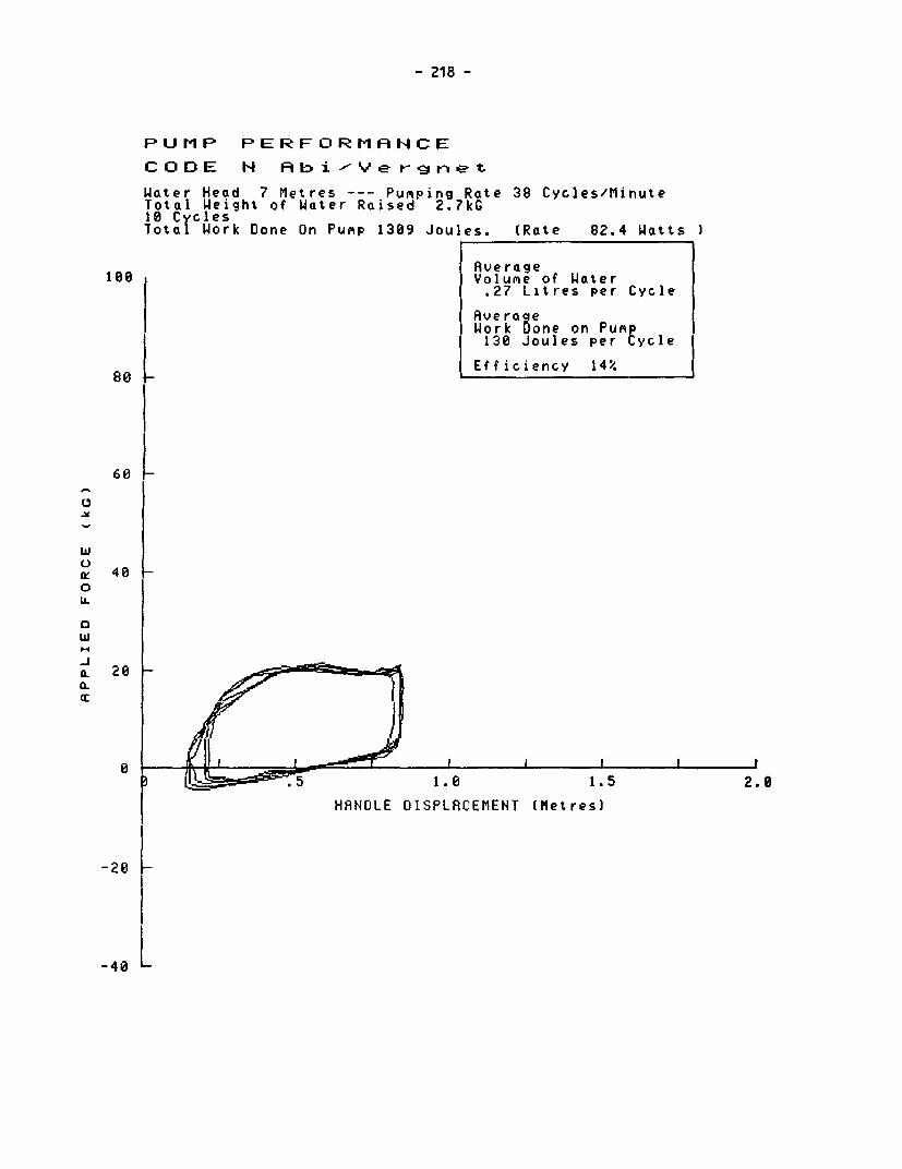
- 218 -
PUMiP PERFORMANCE
CODE N Rbi-Ye rnet
Water Head 7 Metres --- Pumping Rate 38 Cycles/MinuteTotal Weight of Water Raised 2.7kG10 CvclesTotal Work Done On Punp 1309 Joules. (Rate 82.4 Watts
Ave rage1180 Volume of Water
.27 Litres per Cycle
AverageWork Done on PuMp130 Joules per Cycle
8 Efficiency 14%
68L
6
w
g 0 Ux 40 4 L0Ui.
0
a. 20
-0.5 ~~1.6 1.5 2.0
HANDLE DISPLACEMENT (Metres)
-40 L

- 219 -
PUMP PERFORMRNCE
CODE N RAb i ,-Ye irneet
Water Head 25 Metres --- PuMpins Rate 40 Cycles/MinuteTotal Weight of Water Raised 2.6 kG10 CyclesTotal Work Done On Pump 1946 Joules. (Rate 130.9 Watts
Rverage1t0 Volume of Water
.26 Litres per Cycle
AveraqeWork Oone on Pump194 Joules per Cycle
80 | Efficiency 32 l
60 -
I
w
0 40 L0IL
0
03 ~~~~~~1.0 1.520
HANDLE DISPLRCEMENT (Metres)
-20
-40 L

- 220 -
PUMP PERFORMANCE
CODE H Abi YVer r g-e t
Water Head 45 11etres --- Punping Rate 42 Cycles/MinuteTotal Weight of Water Raiseo 2.5kG18 CyclesTota Work Done On Pump 2508 Joules. (Rate 177.4 Watts )
Ave rage100 Volume of Water
.25 Litres per Cycle
AverageWork one on Pum
250 Joules Per Cycle
e _Efficiency 43%.
6 0
0
w
40
IL
w
. 28a.
-29
L4

PUMP PERFORMANCE
CODE 0 Peiro
Water Head 7 Metres --- Pumping Rate 39 Cycles/MinuteTotal Weight of Water Raised 3.8kG15 CyclesTotal Work Done On Punp 1170 Joules. (Rate 50.8 Watts
Rve rage188 Volunie of W4ater.25 Litres per Stroke
RverageWork Done on Pump
78 Joules per Cycle
80 _ Efficiency 22%
6 0
wul
u 400L
w
20
5 ~~~1.0 1.5 2.0
HANDLE DISPLRCEMENT (Metres)
-20 L
-40 L

- 222 -
PUMP PERFORMANCE
C OD E 0 P e t r- o
Water Head 25 Metres --- Pumping Rate 40 Cycles/MinuteTotal Weight of Water Raised 3.7kG15 CyclesTotal Work Done On Pump 1802 Joules. (Rate 79.5 Watts
Ave ragetoo Volume of Water
.25 Litres per Stroke
AverageWork one on Pu 120 Joules per tycle
Efficiency 50%80
640w
4 0
0w
00
i D .~~5 1.0 1.520
4 R>D_ ~~HANDLE DISPLACEMENT (Metresl
- 2 08
-40

- 223 -
PUMP PERFORMANCE
CODE 0 P%e t rco
Water Head 45 Metres --- Pring Rate 37 Cycles/MinuteTotal Weight of Water Raised 4.0kG15 CyclesTotal Work Done On Punp 3032 Joules. (Rate 124.9 Watts
Average100 Volune of Water
.26 Litres per Stroke
AverageWork Done on Punp202 Joules per Dycle
Efficiency 57X88
:60 !
40 40
0e
a.20
IL
-4 '

- 224 -
PUMP PERFORMANCE
COOE P Fun y a c
Water Head 7 Metres --- Punping Rate 38 Cycles/Minute.Total Weight of Water Raised 7.0kG18 C clesTotal Work Done On Punp 1345 Joules. (Rate 86.1 Watts )
Average10d I VoluAe of Water
.70 Litres per Stroke
AverageI Work Done on PuAp
134 Joules per Cycle
80 Efficiency 35.
68Ra L
U 6 Lw
g 400LL
'.w
-j Va.a 20
A ~~~1.5 2.0
HANDLE DISPLACEMENT (Metres)
-28
-4

- 225 -
PUMP PERFORMANCE
CODE P F,umn ya q
Water Head 25 Metres --- Punping Rate 37 Cycles/MinuteTotal Weight of Water Raised 6.;kG18 CyclesTotal Work Done On Pump 3046 Joules. (Rate 188.8 Watts
Ave rage100 Volume of Water
.69 Litres per Stroke
AverageWork One on PuAp304 Joules per Cycle
soEfficiency 55%
60
IL0
w
.-I
A. 20
1.5 2.0
HRNDLE OISPLRCEMENT (Metres)
-20

- 226 -
PUMP PERFORMANCE
CODE P F unay ma i
Water Head 45 Metres --- Pumpins Rate 37 Cycles/MinuteTotal Weight of iater Raised 6.8kC10 CyclesTotal Work Done On PuMp 4687 Joules. (Rate 287.1 Watts
Rve rage100 Volume of Water
1 .68 Litres per Stro
Rvera eWork 8one on Pu e468 Joules peurmEycle
80 e Efficiency 64%
60k
wG 40 Ii ioUi./
0 20a-
0 Il_I I4 II I I
1 t w l.5 2.0
t ~~~HANDLE OIS R MENT (Metres)
_2 0

- 227 -
PUMP PERFORMANCEC OD E R R D w eI r w i t h Su r < Ce C xh inbe r
Water Head 7 Metres --- Pumping Rate 15 Cycles/MinuteTotal Weight of Water Raised 9.0kG5 Cycles
Total Work Done On Pump 960 Joules. (Rate 49.2 Watts
Average o lUMe of Water1.80 Litres per Cycle
AveraBe8Work one on Pum192 Joules per Cycle
Efficiency 64%
60
ly 40_0
U. FC)w~4 L
a. 280
1.0 1.5 2.0
HRNDLE DISPLACEMENT (Metres)
-20L
-40 L

- 228 -
PUMP PERFORMANCE
CODE R R owLer witho>ut Sur g e Choambker
Water Head 7 Metres --- Punping Rate 14 Cycles/MinuteTotal Weight of Water Raised 8.5kG5 CyclesTotal Work Done On Pump 971 Joules. (Rate 46.5 Watts
Average100 Volume of Water
1.70 Litres per Cycle
AverageWork Done on Pump194 Joules per Cycle
Efficiency 59z.80
0 00
w
a. 28a:
0 F- S I ~~~. 0 I .5 2.er
HANDLE DISPLACEMENT (Metres)
-20
-40 LA marginal reduction in efficiency can be seen when the surge chamber is not used.

- 229 -
PUMP PERFORMANCE afet-er erndu ranbc.e
CODE R Ro we r wi th S ur-g e Chambke r
Uater Head 7 Metres --- Pumping Rate 15 Cycles/MinuteTotal Weight of Water Raised 6.5kG5 Cycles
Total Work Done On Pump 1016 Joules. (Rate 50.2 Watts
Rverage198 Volume of Water
1.29 Litres per Cycle
Rvera eWork Done on Putp203 Joules per Cycle
Efficiency 43%.80
68
-)z 400
0
a. 20
-- .> ~~1.0 1.5 2.0
HANDLE DISPLRCEMENT (Metres)
-2e
-40'Considerably higher efforts were noted after endurance, possibly due toincreased friction between the cup seal and cylinder bore.

- 230 -
PUMP PERFORMRNCE
CODE S Vo lr I nt ax w i t h Cy I i n d e r #1
Water Head 7 Metres --- Punping Rate 34 Revs/MinuteTotal Weight of Water Raised 5.6kG9 RevsTotal Uork Done On Pump 879 Joules. (Rate 53.0 Watts
Rve raget88 Volume of Water
.58 Litres per Rev
AverageWork Done on Pump
92 Joules per Rev
Efficiency 43/.
68
600
wuL
x 400b.
aw
I-.
P ~~5 10 V io 20
t ~~~~HRNOLE OISPLRCEM NT (Meyres)
-20
-40By limiting the test to 9 revolutions the initial effort to start the pump
from rest has reduced the average efficiency. This would be higher if the
test was carried-out ever a larger number of revolutions,

- 231 -
P IU P P E R F O R rl A N C E f t e 14d Jr- O n c -
C D 0 E SI 1 a.sl r t r.t. ..i it C *>' 1 i r-e r #1
Water Heod 7 Metres --- Pumping Rate 39 Revs /MinuteTotal Weight of W4oter Raised 4.9kG
9 RevsTotal Work Done On Pump 1015 Joules. (Rate 72.4 Watts
Averagetoo Volun,e of Water
.54 Litres per Rev
AverageWork Lone on PuiSp112 Joules per Rev
80 I Eficiency 32!
E,
w
t 40 Vo ILL
0w
IL 28 0 I
0 JlV2az9Xa44pv~5 20HANDLE DISPLACEMENT (Metres)
-20
I40

- 232 -
PUMP PERFORMANCE
CODE S Voal1antx with Cylirndetr #1
Uater Head 25 Metres --- PuMping Rate 35 Revs/MinuteTotal Weight of Water Raised 3.1 kG9 RevsTotal Work Oone On Pump 1277 Joules. (Rate 80.7 Watts
Average100 Volume of Water
.33 Litres per Rev
AverageWork Done on PuMP136 Joules per Rev
Efficiency 59%80 _
60
0A
w
x 400
0w
a.. 28
CL
t~~~~~ 2 ASX ;i 15 20
HRNDLE DISPLRCEMENT 1Meres)
-28
-40

- 233 -
PU MP PERFORMAP tC E o fiteer- e r d u r- aL r-
C OD E S I V \o) I a tx t L w i tb C y1 i r de # 1
Water Head 25 Metres --- Pumipina Rate 38 Rev-s /MinuteTotal Weight of Water Raised 2.5kG9 RevsTotol Work Done On Pump 1326 Joules. (Rate 94.5 Watts
Average188 I Volumie of Water
.28 Litt-es per Rev
Rvera eWork Done on PumP
147 Joules per Rev
80 Efficiency 46%
60
wuC-
o: 4 00IL
0
ffi 20 -J
a:
0 X 1|/ ttJ X bl 4 X}( X/X 1 20
HANDLE DISPLACEMENT (Metr
-20

- 234 -
PUMP PERFORMANCE
CODE S Vo1, la n t x w it ih Cy I i rndae r #1
Water Head 45 Metres --- Pumping Rate 37 Revs/MinuteTotal Weight of Water Raised 2.3kG
9 RevsTotal Work Done On Punp 1683 Joules. (Rate 113.3 Watts I
Average100 Volune of Water
.25 Litres per Rev
AverageWork Done on Pumt181 Joules per ;ev
Efficiency 60%'80
60 1_ _
w
E 40_
0
w14
a. 20a-
I 5 HN 0 11 pi 0 V \ 1 5 20I 0 HRNO E OI PLACEMENT (Metres)
-20[4
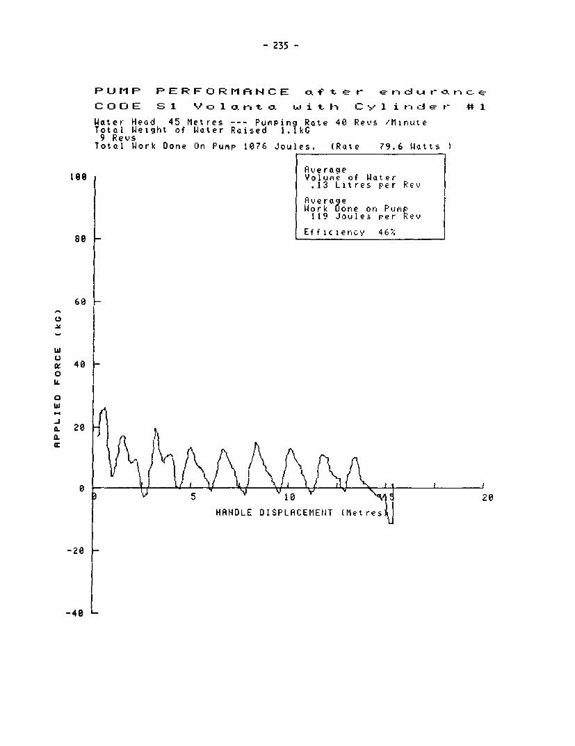
- 235 -
P U P PPERFORMANCE O f tt e r e O. t- o.,- c--
C OD E S 1 V - 1 o.rjt L w i t h C *' 1 i t-.:A - r # 1
Water Head 45 Metres --- Pumping Rate 40 Revs /MinuteTotal Weight of Water Raised 1.1kG9 RevsTotal Work Done On Pump 1076 Joules. (Rate 79.6 W1atts
Averagetee Volume of Water
.13 Litres per Rev
Avera8evork done on Pum119 Joules per Rev
88: |LEfficiency 46.:
60H
w
ax 400IL
0w
0 3 >i2
. ~~~~~HANDLE DISPLACEMENIT IMetres a-2e
-40

- 236 -
PUMP PERFORMANCE
CODE S Voc3L1rxto. with Cylinadein #2
Water Head 7 Mletres-- Puriping Rate 37 Revs/MlinuteTotdl Weight of Water Raised 5.8kG9 RevsTotal Work Done On Pump 1127 Joules. (Rate 73.3 Watts
five rageiee ~~~~~~~~Volume of Water
I ~~~~~~~~.61 Litres Per RevAverageWorkD one on Pum118 Joules per ;e v
80 ~~~~~~~Efficiency 35%
60
0
ILI
Cc
HANDL DISPL CEMEHT (Metres)
-2e

- 237 -
P Li M P P E R F OR 1 tA N C E a f t e r e rd r ct U- rC.k c e
C O D E S 2 V YD 1 oa. t. o L ...I i t C 1 i re- d E- t- 442
Water Head 7 Metres --- PupipinQ Raote 37 Revs /1inuteTotal Weight of Water Raised 50.kG
9 RevsTotal Work Done On Pump 1376 Joules. (Rate 88.2 Watts
Yoluie of Water .53 Litres per Rev
Average IWork Done on PUMP144 Joules per Wev
8I~- I_Eificien,cy 24%8 60
v
w_ 40
0
IL I
w-jO. 20
a:p
0~~~~~ 1 20
HANDLE DISDPLACEMENT (Met res)
-20=
-40

- 238 -
PUMtP PERFORMANCE
C O D E S Vo r 1 bn t a w i t h C y inder #2
Water Head 25 Metres --- Pumping Rate 37 Revs/MinuteTotal Weight of Water Raised 3.2kC9 RevsTotal Work Done On Pump 1427 Joules. (Rate 93.1 Watts
1ve ragelee Volume of Water
.34 Litres per Rev
Work Done on Pup151 Joules per Rev
880 Efficiency 54%
60L-,
wC.)a 40
oX)0
0
-J
'I1, L\0 10 20
HRNOLE DISPLACEMENT (Metres)
-40L

- 239 -
P IJ MP PERFORMANCE cL f t, IL r rid t- r- b. c- E
C iD E S 2 V u l*,.r- tc .t wkL i t i » -1 i t-I id8 t- # 2
(Joter Heod 25 Metres --- PuMpin Roate 35 Revs 'lirnuteTotol Weight of lloter Roised 2. kC
9 RevsTotal Work Done On Pump 1617 Joules. (Rote 98.7 Wotts
Aver agae100 olume of Water
.29 Litres per Rev
Avero eWork gone on PuMevi170 Joules per Ieu
Efficiency 41%
64
wI
IW. 41 0
a. jA~~~~~~~~r L t Xfl ),lrvf ,lSSHD I SP0 LEe re)0
l ~~~~HANDLE DISPLACEMENT lMetresl

- 240 -
PUMP PERFORMHNCE
CODE S VoI xno ta wilt h Cylirndke-r #2
Uater Head 45 Metres --- Pumping Rate 36 Revs/MinuteTotal Weight of Water Raised 2.4kG9 RevsTotal Work Done On Pump 1792 Joules. (Rate 115.3 Watts
Average180 Volume of Water
.25 Litres per Rev
AveraeWork one on PuRp190 Joules per Rev
80 Efficiency 58x
60
C
w
QC 400IL
w1*
28 2i
~~AJ _ 26
HANOLE DISPLRCEM NT (Metres)
.. 1
-40

- 241 -
P U tr P PERFOR11AtNCE a f t, r er L C- JLA- n C- E
C 0 J E S V 2 1 a o t -a ILi i t C- : ' 1 i t-r . -r E 4 -1
Woter Heod 45 Metres --- Pumpir,q Rote 4E1 Revs 'MinuteTotal Weight of Water- Rnised 1.4kG
9 RevsTotal Work Done On Punp 1154 Joules. (Rote 81.0 Wlatts
Average100 I Volume of Water
.14 Litres per Rev
AverageW Aor k one on Purp121 Joules per Rev
Efficiency 52.
80K
ILl
'0_
1.1 a.
20K
X FlAlalkl^AmA/leFl' n r~IV5 10 'U If ~20
HANDLE DISPLACEMENT (Metres)
-20

- 242 -
PUMP PERFORMANCE
C OD C, E i K-D r- 't 608 A - I
Water Heod 45 Metres --- Pumpinr Rate 40 Cycles 'MinuteTotal Weight of Water Raised 6. kC20 CyclesTotal Work Done On Pumxp 4001 Joules. (Rate 133.1 Wotts
1 00 Volumere of Water.35 Litres per Cycle
AverageWork Done on Pump200 Joules per Cycle
Efficiency 76%
00
4 0
Li
'-
t 0
Ja. 20Lr
00
8 t~~~. 1.0 1.52 0
HANDLE DISPLACEMENT (Metres)
-28h-

- 243 -
PUMP PERFORMANCE acf te-r er *ds*n a ctriC.e
CODE A Kco t-oat 608 A-1
Water Head 45 Metres --- Pumpint Rate 36 Cycles /MinuteTotal Weight of Water Raised 3. kG10 CyclesTotal Work Done On Pump 2539 Joules. (Rate 154.3 Uatts
100 yR~~~~~~~~verage llee Volume of Water.35 Litres per Cycle
Rverag eWork Done on Pum253 Joules per Cycle
S0 |Efficiency 61%
68
wu
ay 400tL
0w
sIL
.20
1.0 1.5 2.0
HANDLE DISPLACEMENT (Metres)
-20
-40 LThe diagrams illustrate the effects of wear in the pumpstand rack and guadrant:
(a) greater handle displacement for the same volume flow(b) increased frictional losses, particularly at the start of the return stroke.
Initially, the weight of thie rods was sufficient to reverse the direction ofmotion. After endurance testing, the operator had to apply an immediate upwardforce at the start of the return stroke. The increase in friction is confirmedby a 25%o increase in the recorded work done on the handle.

- 244 -
PUMP PERFORMANCEC O D E B 0 r-ago r N o . 2
Water Head 45 Metres --- Pumping Rate 37 Cycles /MinuteTotal Weight of Water Raised 5. kG10 C clesTotal Work Done On Punp 3669 Joules. (Rate 229.1 Watts
Avzerage100 Volune of Water
.53 Litres per Cycle
Avera eWork gone on Pump366 Joules per Cycle I
Efficiency 63%:80_
I,
wUlm 40 _0
0w
oJ 20
HRNDLE DISPLACEMENT (Metres)
-20
-40:

- 245 -
PUMP PERFORMANCE oxftietr- ENDIURANCE
CODE B DOraco>n No.2
Water Head 45 Metres --- PuMpin? Rate 40 Cycles /MinuteTotal Weight of Water Raised 5.3kC10 Strokes/RevolutionsTotal Work Done On Pump 3271 Joules. (Rate 215.9 Watts
I AverageI Volume of Water
100 .53 Litres per Cycle
RverageWork Done on Pump327 Joules per Cycle
Efficiency 70%
60
w
Lv
me 40 F0
w
(L 20
.5 - 2.0
HAHDLE DISPLRCEMENT (Metres)
-20 _-
-40The irregularities on the power stroke are probably caused by variationsin the linkage friction due to the wear which has taken place in thelinkage mechanism.
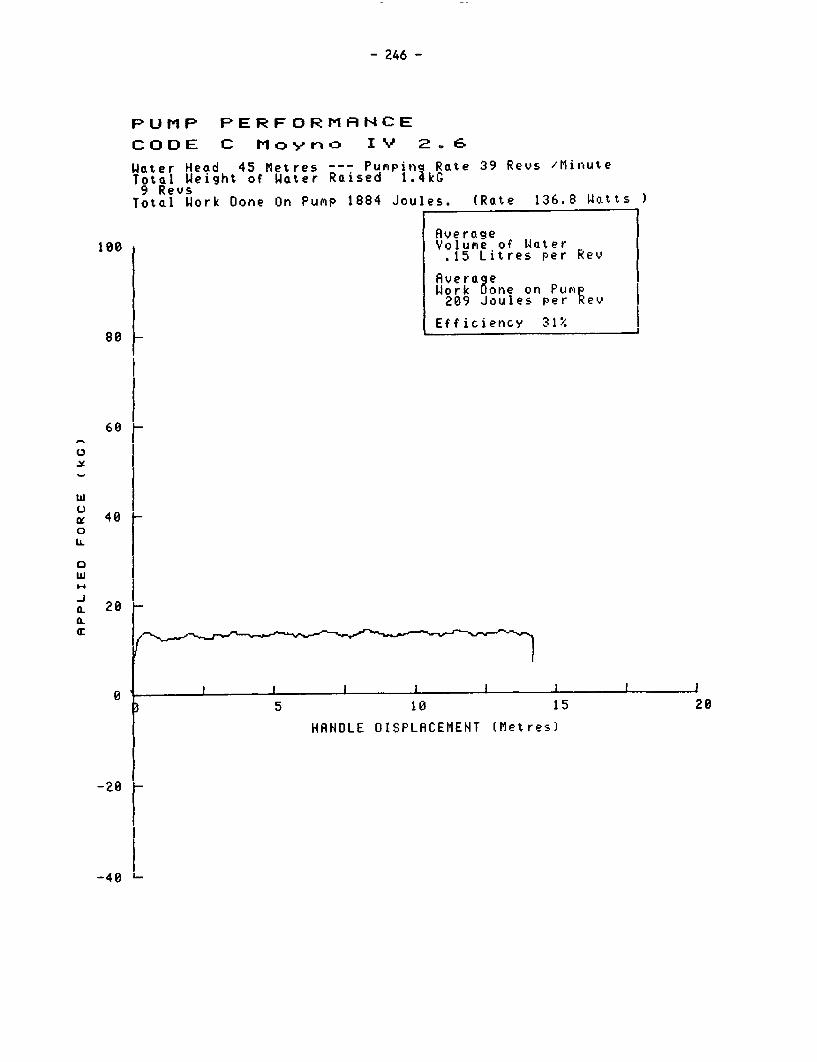
- 246 -
PUMP PERFORMANCE
CODE C Mo>n<o I IV 2.6
Water Head 45 Metres --- Pumpinq Rate 39 Revs /MinuteTotal Weight of Water Raised 1.4kG9 RevsTotal Work Done On PumP 1884 Joules. (Rate 136.8 watts
Average108 Volume of Water
.15 Litres per Rev
AverageWork kone on Pump209 Joules per Rev
Efficiency 31%80 _
60
w
m 40
IL
0
a. 20a.
5 10 15 20
HRNDLE DISPLACEMENT (Metres)
-280
-4 I

- 247 -
PuM P PERFOR?t1AINCE atfter EADUIJPFHACE
C OD E C Mo .' y r) cz I V 2 . 6
WatAer Heod 45 Metres --- Pupiping Rate 40 Revs 'MliriuteTota.l Weight of Wa.ter Poised 1.;kG
9 St roPEs"FevOlut ionsTotal Wotrk Done On Pump 1234 Joules. (Rate 91.8 Wotts
|RAerageI Volume of Woter
180 .18 Litres per Rev
Avera cieW4ork Oone on PupiI137 Joules per Rev I
I8 L Efficien',:v 5C%
48.6,
40_
U.
-j 28
EL-J
0~ ~ ~~ ~ ~ ~ ~~~~ 1 j I t5 18 15 C4
-28H HANDLE DISPLACEMENT (Metres)
The irregularities on the curves are probably due to system noise.
The diamgrams indicate a reduction of friction combined with an increase
in volume flow.

- 248 -
PUMP PERFORMRNCE
CODE D Noe p to.
Water Head 45 Metres --- Pumpin? Rate 40 Cycles 'MinuteTotal Weight of Water Raised 7.(kG20 CyclesTotal Work Done On Pump 4326 Joules. (Rate 143.8 Watts
Aver ageVolume of Water.39 Litres per Cycle
Avera eWiork one on Putip216 Joules per Cycle
Efficiency 78%
60H
40C.)
UL.0 0
wo I
a. 20a.
0 0Z IJ
-20

- 249 -
PUMP PERFORMANCE cLf t e r- encLIu ro.rnc.e
CODE 0 Nepta
Water Head 45 Metres --- Pumping Rate 42 Cycles /MinuteTotal Weight of Water Raised 4.3 kG10 CyclesTotal Work Done On Pump 3517 Joules. (Rate 247.2 IJatts
Averagetoo Volume of Water
.43 Litres per Cycle
AverageWork Done on Pump351 Joules per Cycle
Efficiency 54%:80
60
X
wC.)g 40
L-
0w
9L 20
00 ..5 1.0 }}1.5 2.0
~~~~~~~~~T e s)
-20
-40. '.The results show that the work done on the handle increased by over 50%O afterendurance, with a small increase in volume flow. Friction had thereforeincreased considerably, probably as a result of the failure of the upperplunger seal.
The change in the profiles of the curves probably illustrates the removal ofthe return spring.

- 250 -
PU IFP PERFORMrANCE
C C D E E K' e t -,
Wnater Head 45 Metres --- Pumnpinc Rate 40 Cycles /MinuteTotal Weight of Water Raised 7.;kG10 CyclesTotal Work Done On Pump 5280 Joules. (Rate 355.4 Watts
Aver a getoo Volume of Water
.76 Litres per Cycle
AverageWSork Done on PuePi528 Joules per Cycle
Efficiency 63.80
60e
w
0 40 -
0w
a. 20 ..
HANDLE DISPLACEMENT (iMres) d4
-28 F

- 251 -
PUMP PERFORMARtCE Lf t,r ENDIURA NtCE
CODE E Kse n yc
Woter Head 45 Metres --- Pumpina Rate 40 Cycles 'MinuteTotal Weiglht of Water Raised 7.;kG10 Strokes/RevolutionsTotol Work Done On Pump 5945 Joules. (Rate 397.2 Wo.tts
AverogeVolume of Woter
too .76 Litres per Cy)cle
AverageWork Oone on Pupip594 Joules Per cycle
Efficiency 56%:
80 I I
60
0
48 I
gil
40
a:2
I
20
-2 0
-4 L
Differences between the profiles of the curves before and after enduranceare the result of severe wear at the handle pivot.
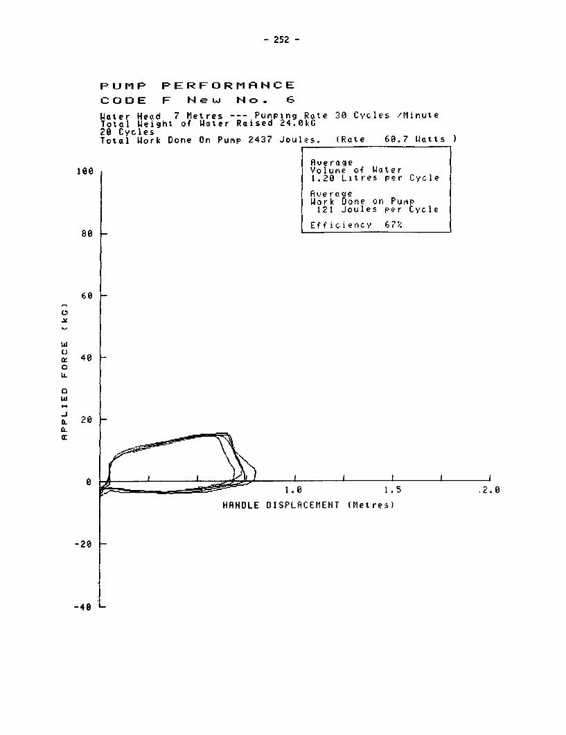
- 252 -
PUMP PERFORMANCECODE F Ne w Nco . 6
Water Head 7 Metres --- Pumping Rate 30 Cycles /MinuteTotal Weight of Water Raised 24.0kG20 CyclesTotal Work Done On Pump 2437 Joules. (Rate 60.7 Watts
Avera~g e19 e Volune of Water
1.20 Litres per Cycle
Ave rc eWork gone on Puip121 Joules per Cycle
8 Efficiency 67%80
60 -
wuOf 40
0IL
w
a 20
00
0 ~~~~~~~1.0 1.5 . .
HANDLE DISPLACEMENT (Metres)
- 2 F
-4

- 253 -
PUMP PERFORMANCE oLf te - e)r d .uri- a ce
CODE F Nke w No.6
Water Head 7 Metres --- Punping Rate 30 Cycles /MinuteTotal Weight of Water Raised 5.1kG5 Cycles
Total Work Done On Pump 647 Joules. (Rate 64.6 Watts
Rverage180 Volune of Water
1.01 Litres per Cycle
Rvera eWork one on Pump129 Joules per Cycle
Efficiency 53%.68
60_
wz 40 LI...
0 2
s ~ ~ ~ ~ ~ ~ ~ ~ ~ ~ ~~~~~~~~~~~~~~~~2 _a.~_15 .
HANDLE DISPLACEMENT (Metres)
-20
-40Differences between the profiles of the curves before and after endurance
illustrate increased lost motion in the handle pivots.

- 254 -
PUMP PERFORMtANCE
CODE G Hi r-L AhF76
Water Head 25 Metres --- Pumping Rate 40 Cycles /MinuteTotal Weigl7t of Water Raised 12.9 kG20 CyclesTotol Work Done On Pump 4186 Joules. (Rate 140.4 Watts
Average18C Volume of Water
.65 Litres per Cycle
Avera eWork Done on Pump209 Joules per Cycle
80 | Efficiency 75%.
00
w
bu
W. 48 _0
IL
'L 20
1.0 I1.520
HANDLE DISPLACEMENT (Metres)
-20

- 255 -
PUMP PERFORMANCE o.f t e r erndu r- c e
CODE G Ni ra. FF76
Water Head 25 Metres --- Pumping Rate 40 Cycles 'MinuteTotal Weight of Water Raised 6. kG10 CyclesTotal Work Done On Pump 2186 Joules. (Rate 145.6 Watts
188 ~~~~~~~~Ave rage100 | RVolume of Water.65 Litres per Cycle
AverageWork one on Pumnp218 Joules per Cycle
Efficiency 72;'80(-7.
60
w
C) Ic 40 f0
20
F ~~~.5 1.0 1.5 2.0
HANDLE DISPLRCEMENT lMetres1
-20
-40 -Differences in the profiles of the curves at the beginning of the deliverystroke, and the reduction of effort on the return stroke, probably illustratethe improved conformity of the rubber cup washer after bedding in.

- 256 -
PUMP PERFORMANCE
C O D E H E t tb i .D i a T R EB P 5 Ct
Water Head 7 Metres --- Pumping Rate 38 Cycles /MinuteTotal Weight of Woter Raised 6.2kG10 CyclesTotal Work Done On Pujip 1177 Joules. (Rote 74.2 WJatts
| ver-oge18t Volu:ie of Water
.62 Litres per Cycle
AverogeWork Done on Pu,rp I
117 Joules per Cycle
Efficiency 35%8Q -
60C,
-)re 400Li-
0w
a. 28
0.
8 ,.- I 1 1 1 1 1.5 1.0 1.5 2.0
HANDLE DISPLACEMENT (Met res)
-28
I ~~
-4
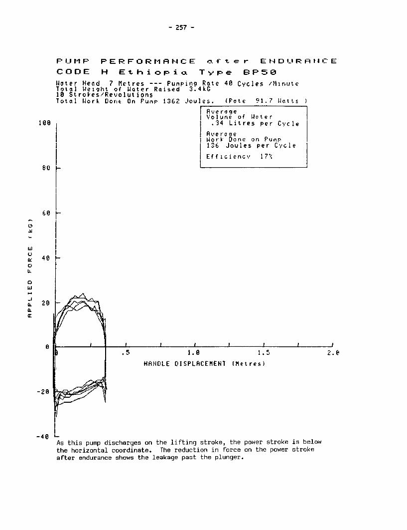
- 257 -
PIJMP PERFORMR1NCE ot'ftevr ENDURAt4ICE
CODE H Ethi o pioa Typp e BP50
W4ater Head 7 Metres --- Pumpiing Rate 40 Cycles /MinuteTotal 1Weilght of Water Raised 3.4kG10 Strokes/RevolutionsTotal W4ork Done On Pump 1362 Joules. (Pote 91.7 Watts
AverageVI Volur'e of W4oter
100 1 1 .34 Litres per Cycle
| Averoqeioork Done on Pump
I 1 136 Joules per Cycle
Efficiency 17?
60I
iI
Ca: 48 0coIL
0w
P ~~~.5 1.0 1.5 2.
I ~~~~HANDLE DISPLACEMENT (hetres)
-20
-40As this pump discharges on the lifting stroke, the power stroke is belowthe horizontal coordinate. The reduction in force on the power strokeafter endurance shows the leakage past the plunger.

- 258 -
PUMP PERFORMANCE
CODE J VELW
Water Head 45 Metres-- Pum'pinq Rate 30 Revs /MlinuteTotal Weight of Water Raised 5.. kG9 RevsTotal Work Done On Pump 3866 Joules. (Rate 212.9 Watts
Ave rage100 Volume of Water
.62 Litres per Rev
RveroaeWork one on Pump429 Joules per Rev
so0 Efficiency 63%
6 80
-,
w~~~~~
40fL \ H 'ND VLLR IET Iet
-20-J Ia. 20I'
115 y20HANLE PLA MENT .Metrel

- 259 -
PUMP PERFORMANCE oa fitr Et-IILIF:AIIC E
CODE J VEW A18
1Joter Head 45 Metres --- PuMping Rate 27 Revs 'IlinuteTotal Weight of Water Raised 3.8kG9 Strokes/RevolutionsTotal Work Done On Pump 2943 Joules. (Rate 148.6 lIlott;)
AverageiVolumue of W4ateer
Is. .42 Litres per Rev
Rver-aqelior-k Oone on Purwr327 Joules per Rev
Efficiency 561
80
60
C,
-20_
II N II L I I I A EM. ," i
20
-40 0
The results before and after endurance should not be directly compared becausethe plunger seal was replaced during the endurance test. Differences in theprofiles of the curves may also reflect the changed position of the handlecounterweights.

- 260 -
PUMP PERFORMANCE
C O D E K J e t r xt i c
Water Head 45 Metres --- Pumpin? Rate 41 Cycles /MinuteTotal Weight of Water Raised 5.7kG20 CyclesTotal Work Done On Pump 3461 Joules. (Rate 119.3 Wattsl
Rverage188 Volune of Water
.28 Litres per Cycle
AverageWork Oone on PuMP173 Joules per Cycle
Efficiency 72%
60
w
a: 4080IL
4..w
-j Va: ~ ~ ~ ~ .52
HANDLE DISPLACEMENT (Metres)
-20
-40 L

- 261 -
PUMP PERFORMAHCE oft,r ENDIJRA[4CE
CODE K .Jetgr)o. t i C
Woter Hecod 45 tletres --- Pumpinq Rate 41 Cycles /MinuteTotal Weight of Woter Raised 2.9kG18 StrokesRPevolutionsTotol Work Done On Pupip 1393 Joules. (Rate 94.3 Watt )
Volufie of llater-100 .29 Litres per Cycle
Avera.e1 ork onie on Pupr!1319 Joules per tycle
t Efficicnc.' 91I.
60
C.R
Uw 40 Loz ItL I
oJ I
CiL I
.
0 I r ~ ~ ~~ 1.1 0 .
HA1HDLE DISPLACEMENT (Metres)
-40 LThe results illustrate reduced friction after endurance testing.

- 262 -
PUMP PERFORMANCE
C O D E L B x ztdj u r-
Water Head 7 Metres --- PuMiping Rate 29 Cycles /MinuteTotal Weight of Water Raised 19.3kG20 CyclesTotal Work Done On Pump 1874 Joules. (Rate 44.7 Watts
Rverage100 Volume of Water
.96 Litres per Cycle
AverageWork Done on PumP
93 Joules Per Cycle
Efficiency 70%80
6 0
t 40CUi.
Cw
-J0- 20_0-
0 I A 11 ^~''- __ _--~~~!1.0 1.5 2.0
HRNOLE DISPLACEMENT (Metres)
-201
-40 '-
The results before endurance testing suggest some irregularities in the
performance of the plunger seal or valve.

- 263 -
F-U t1 P P E R F O R tl I N C E o.f t- t
C O D E L BE-rt .- L 4A gJ r
Water -Heod 7 Metres --- PuMpirig Rote 30 Ctycles /MinuteTotal Weight of Water Raised 5.?kG
5 CyclesTotol Work Done On Pump 625 Joules. tRate 62.5 Watts
AverageI100 Volutie of Wloter|
1.13 Litres per Cycle
AveroqeLWork Oone on Pump125 Joules pe r Cycle
Efficiency 62%
6Lw
CC 4 0lL
0w
Ci 20CL
HANDOLE 01ISPLACEMENIT (Mete
2 1
-40 LNo irregularities are indicated, suggesting that the plunger seal and valvewere working satisfactorily during this test. Note that the plunger seal was
replaced three times during the endurance test.

- 264 -
FUr1P PERFORMFNCECODE M SurMber BSu -vu
laoter Heod 45 Met res --- Pumpinq Rate 39 Cycles /MinuteTotal Weight of Water Raised 8.60kC10 CyclesTotal Work Done On Pumip 4809 Joules. (Rote 311.6 Wotts
Average100 Volurne of WJater
.80 Litres per Cycle
Ave ro ellWork Done on Pum p
480 Joules per Cycle
t Efficiency 73"'.
8Yf
w
40
0 I === ~~~ ~ ~ ~~~1. 5 2. 0
| 1' MENT l~~~MNT Metres1
020
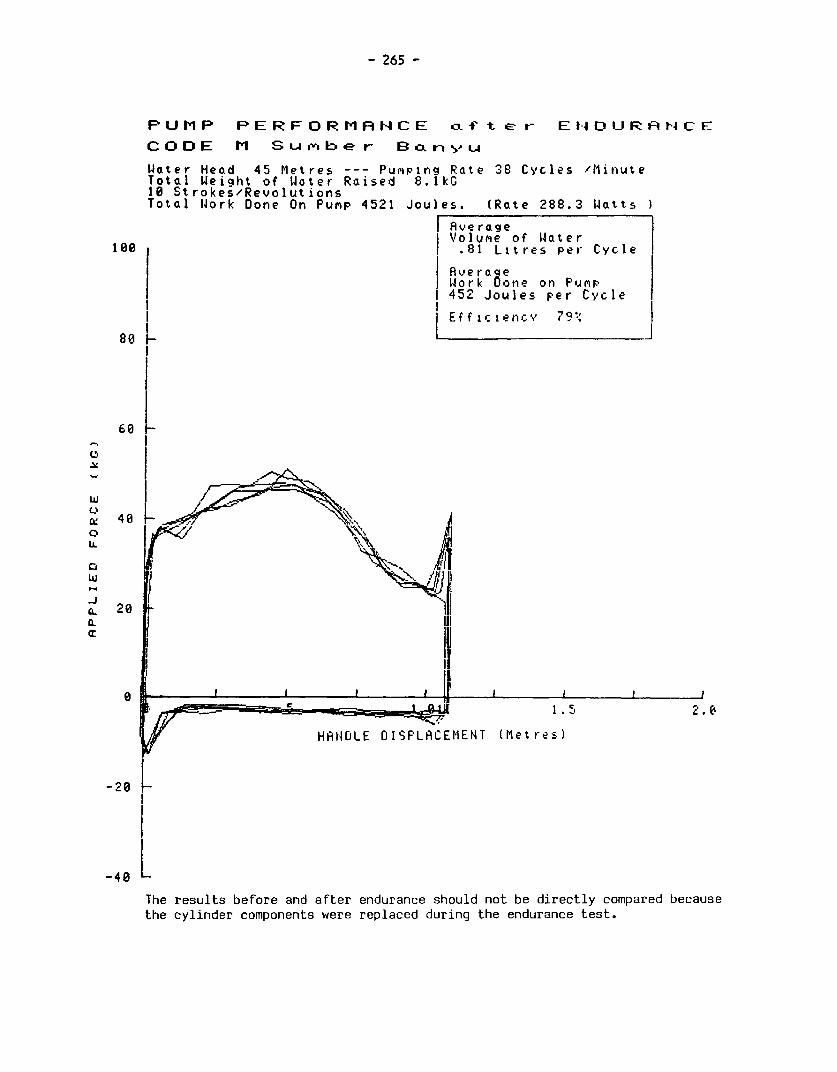
- 265 -
PUMP PERFORMANCE of t e r- EIADURANCE
CODE M Siub e r Bo.?-!-Lu
Water Head 45 Metres --- Pum^ping Rate 38 Cycles IlMinuteTotal IJeight of Woter Raised 8.1kG10 Strokes/RevolutionsTotal IJork Done On Punp 4521 Joules. (Rate 288.3 Watts
| AverageVolume of Water
100 .81 Litres per Cycle
Aver aqeWork Oone on Pump
I 452 Joules per Cycle
Eff icienc v 7q9I
80_-
60
EC 408_ .
281 ,> , •1 ,. O - _ # t F ~~~~~ ~~~~~1.5' o
HANDLE DISPLACEMENT (Metres)
-2081
-48
The results before and after endurance should not be directly compared because
the cylinder components were replaced during the endurance test.

- 266 -
APPENDIX III. ABSTRACT OF ODA HANDPUMPS LABORATORY TESTING
FINAL REPORT, JANUJARY 1981
C0 Manufacturer Deep/ Ex-Factory * Type of Ease ofD (Country of Model shallow Cost per pump pump MaintenanCeE origin) & repair
A Petropump Hand-operated(Sweden) Type 95 Deep #221.5 (excluding diaphragmatic 3
pipe) hose
Foot-operatedB Vergnet Hydropompe Deep #421.7 (complete hydraulic oper- 4
(France) Type AC 2 to 50m) ation, diaphra-gmatic hose
C Dempster #56.5 Hand-operatedTUSA 23 F(CS) Deep (excl. pipe lift pump 2
and rod)
D Mono #370.4 Hand-operated(England) ES 30 (complete to rotary, helical 2
10m) screw-typeoperation
E Climax Not Deep #730.9 Hand-operated(England) stated (complete to flywheel-lift 1
21m) pump
F Godwin Wl H51 Deep #865.5 Hand-operated(EngLand) (complete to 21m) geared lift pump 1
G ABI Type M Deep #358.3 Hand-operatedTl-ory Coast) (Excl. pipe & lift pump 2
rod)
H GSW (Beatty) 1205 Deep #163 (Excl. pipe Hand-operated(Canada) and rod) lift-pump 2
J Monarch P 3 Deep #359 Hand-operated(Canada) (complete to 30m) lift pump 2
K Kangaroo Not Deep #282.5 (complete Foot/Spring-(Holland) stated to 20m) operated lift pump 2
L India Mark II Deep #64.9 (excl. Hand-operated(Ti =Ta) pipe and rod) lift pump 2
M Consallen L D 5 Deep #296.8 (complete Hand-operated(England) to 20m) lift pump 3
* Price basis late 1977/early 1978 equivalent in #
Note: This information was compiled in 1981 and has been included forcompleteness.. Many manufacturers, however, have since modifiedtheir pumps as a result of both laboratory tests and field infor-mation.

- 267 -
Results of Endurance Test
Hours Failures Performance Reliability Wear
670 Pumping element disconnected. 962/ Adequate but Somewhat Likelynut on handle loose. 1636/ pumping low efficiency variable to beelement split. 2848/pumping element smallfailed. 3212/pumping element split
1317 Significant wear in pedal rod guide Acceptable, Fairly goodlow efficiency
2000 Pedal rod guide worn right through
930 Pump rod broken. 1130/pump rod Good Poorbroke again. 3037/s-plit pin onhand fulcrum bearing fractured
No failures occured. (However, Poor Very goodcontinual oil leakage fromgearbox)
1323 Water leaking from pumpstand Good Very good Likelyinspection covers. 1355/ Handle to befractured minimal
No failures occurred Adequate Excellent
No failures occurred Good Good in test Unlikelybut sharp to causemetal/metal problemsstops maycause fieldproblems
No failures occured Fairly good Quite good
2772 Wooden handle loose. Pump rod Good Quite good3692 top guide bush worn through
251 Spring in pumpstand broken Poor Very poor400 No spares, pump removed from test
No failures occurred Fairly good Excellent Unlikelyto be aproblem
No failures occurred Quite good Very Good
Rating : 1 poor, 5 very good
World Bank 4 NEW
Publications Ventilated Improved Pit
of Related Latrines: Recent Developments3 _ t * t inZimbabwe
Interest 5 s # s X t D. D. Mara and Peter R. Morgan
Describes designs and matenals for la-trines, one for peri-urban areas costingabout US$150, and a US$8 version for
1 ]S1 -1 99() {rural areas. Some 20,000 of the venti-*1w * *9WBv lated pit latrines have been built in
Zimbabwe. They have been foundvery effective in eliminating odors and
NEW A Model for the Development controlling fly breeding.AEWOf a SMoelforelp terDevelo Technical Paper No. 3. 1983. 48 pages.
ofboratory alti Self-Help Watem SISBN 0-8213-0078-4. Stock No. BK 0078.Laboratory Evaluation of Program 3Hand-operated Pumps for Use Colin Glenniein Developing Countries Presents one version of a practical Village Water SupplyConsumers' Association Testing model for developing, with high com- Describes technical aspects, costs, andand Research Laboratory munity participation, water supply institutional problems related to sup-An invaluable guide for selecting programs in developing countries plying water for domestic use in ruralwater pumps. Paper rates 12 pumps Consideration is also given to sanita- areas and proposes guidelines for fu-on basis of ngorous testing to deter- tion program development and practi- ture World Bank lending in this sector.mme their strengths and weaknesses. cal guidelines for program develop-Pumps rated for packaging, condition ment are included. One of a series of A World Bank Paper. 1976. 98 pages (in-as received, installation, maintenance, informal Working Papers prepared by cuding 4 annexes).repair, and overall desirabiity. the Technology Advisory Group, es- Stock Nos. BK 9099 (English), BK 9100
Technical Paper No. 6. 1983. 89 pages. tablished under UNDP's Global Proj- (French), BK 9044 (Spanish). $5.ISBN0-813-133-. SockNo. K 033. ect, executed by the World Bank.
ISBN 0-8213-0133-0. Stock No. BK 0133. Technical Paper No. 2. 1982. 45 pages (in- Village Water Supply:Laboratory3Testing, Field cluding 2 annexes, references). Economics and Policy in theLaboratory Testing, Field ISBN 0-8213-0077-6. Stock No. BK 0077. Developing WorldTrials, and Technological $3. Robert J. Saunders and Jeremy J.Development WarfordContams results of laboratory tests car- Municipal Water Supply Addresses the problem of potableried out on twelve hand pumps for the Project Analysis: Case Studies water supply and waste disposal in ru-World Bank and presents recommen- Frank H. Lamson-Scribner, Jr., ral areas of developing countriesdations for improvements in perfor- and John Huang, editors where the majority of the poor tend tomance, safety, and durability. Eight case studies and fourteen exer- be found. Emphasizes the economic,1982. 122 pages (including 3 appendixes). cises dealing with the water and was- social, financial, and administrative is-Stock No. BK 9190 $5. tewater disposal sector. sues that characterize villae water sup-
World Bank (EDI), 1977. 529 pages. ply and sanitation programs.NEW^ Stock No. IB-0655. $8.50 paperback.The Johns Hopkins University Press, 1976.NEW yv Stock No. IB-0655. S8.50 paperback. 292 pages (including 4 appendixes, bibliog-
Meeting the Needs of the Poor raphy, index).for Water Supply and Waste NEW LC 76-11758. ISBN 0-8018-1876-1, StockDisposal No. IH 1876, $22.50 hardcoverFredrick L. Golladay Notes on the Design and French: L'alimentatzon en eau des commu-
of Waste ~~~~~nautes rurales- economie et politique gener-Examines economic, political, social, Operation of Waste ale dans le monde en developpement. Econ-and cultural obstacles to meeting the Stabilization Ponds in Warm omica, 1978.needs of low-income people for water Climates of Developing ISBN 2-7178-0022-0, Stock No IB 0549,supply and waste disposal. Proposes Countries e7 1steps to reduce these obstacles. Notesthat communities organize and man- J. P. Arthur Spanish: Agua para zonas rurales y pobla-age resources to carry out acbvities Practical design criteria for pond sys- dos: economia y politica en el mundo enthat cannot be profitably undertaken tems to fit various ambient tempera- desarrollo Editorual Tecnos, 1977by households. Proposes methods to ture and reuse requirements, such as ISBN 84-309-0708-4 Stock No. IB 0532.facilitate the formation and operation irrgation. Offers suggestions for start- $7of community organizations to carry up procedures, operation, and troubleout these functions. shooting.Technical Paper No. 9. 1983. 66 pages. Technical Paper No. 7. 1983. 106 pages.ISBN 0-8213-0238-8. Stock No. BK 0238. ISBN 0-8213-0137-3. Stock No. BK 0137. Prices subject to change without notice$3. S5. and may vary by country.

NEWNEW World Bank Studies in Water
Supply and Sanitation Number 3: Sanitation andThe United Nations has designated the Disease: Health Aspects Of
Project Preparation Handbook 1980s as the Intemational Dnnking Wastewater ManagementThe three companion volumes Water Supply and Sanitation Decade. Richard G. Feachem, David J.guide planners, engineers, and Its goal is to provide two of the most Bradley, Hemda Garelick, and D.community development and fundamental human needs-safe water Duncan Marapublic health specialists working in and sanitary disposal of humanprojects related to water and wastes-to all people To help usher in Summarizes knowledge about excreta,sanitation hp user relopig c trojet this important period of intemational night soi andescnbes the environ-sanitto h ndeeloses prepag counetre research and cooperation, the World mental characteristics of specific ex-
each phase of project on appropnate technology for water creted pathogens and the
development: identification, developing countries. Since the tech- tions these pathogens cause.prefeasibility, and feasibility. nology for supplying water is better John Wiley and Sons (U.K ) 1983 528Suggests approaches and methods understood, the emphasis in these vol- pagesof project evaluation to guide umes is on sanutation and waste recla- ISBN 0-471-90094-X. Stock No IB 0558.project team members. mation technologies, their contribu- $39.50 hardcover
tions to better health, and how they_ . ~~~~~~~are affected by water service theyesn Appropriate Technologiy forareafeced y atr srvcelevels and Water Supply and Sanitation
WSW _.WY .d S..,tt-. the ability and willngness of commu-Piy P ,ti. o Hdb-k nities to pay for the systems. The following volumes have been pub-
lished in a less formal format Some_- IRlbNumber 1: Appropriate are abridgments of the three foregomg
Sanitation Alternatives: A volumes.Technical and Economic Volume 1: Technical andAppraisalVoue1Tehiaan
El .^> , John M. Kalbermatten, DeAnne S Economic OptionsJulius, and Charles G. Gunnerson John M. Kalbermatten, DeAnne S.This volume summarizes the technical, Julius, and Charles G. Gunnersoneconomic, environmental, health, and Reports technical, econonmic, health,sociocultural findings of the World and social findings of the researchBank's research program on appropn- project on "appropriate technology": ,j ate sanitation alternatives and dis- and discusses the program planningcusses the aspects of program plan- necessary to implement technologies
Volume 1: Guidelines nng that are necessary to implement ronentably acceptable low-cost waterBrian Grover these findings. It is directed primarily roupntaly accepatabe low-osta wte
toward planning officials and sector supply and waste disposal.Technical Paper No. 12. 1983. 190 pages. policy advisers for developing coun- 1980. 122 pages (including bibliography)
ISBN 0-8213-0230-2. Stock No. BK 0230. tries. Stock No BK 9186. $5.S5. The Johns Hopkins University Press, 1982
Volume 2: Case Studies- 172 pages (including bibliography, mdex). Volume la: A Summary ofVolue 2 Cae Sudis- C 8-896. IBN -808-278-, Sock Technical and EconomicIdentification Report for Port No. IH 25786 ISBN0801825784 Stock 9 p OptionsCity, Immediate Improvement N John M. Kalbermatten, DeAnne S.Project for Port City, Pre- Number 2: Appropriate Julius, and Charles G. Gunnersonfeasibility Report for Port City Sanitation Alternatives: A A summary of the final report on ap-Brian Grover, Nicholas Burnett, Planning and Design Manual propriate technology for water supplyand Michael McGarry John M. Kalbermatten, DeAnne S. and waste disposal in developingTechnical Paper No. 13. 1983. 352 Julius, Charles G. Gunnerson, and countries, a World Bank research proj-pages. D. Duncan Mara ect undertaken by the Energy, Water,
ISBN 0-8213-0231-0. Stock No. BK Thls manual presents the latest field and Telecom1 unications Departnent0231. $15. results of the research, summarizes se-
lected portions of other publications 1980. 38 pages.Volume 3: Case Study- on sanitation program planning, and Stock No. BK 0049. $3.
Feasibility Report for Port City describes the engineering details of al-Brian Grover, Nicholas Bumett, ternative sanitation technologies and Volume lb: Sanitationand Michael McGarry how they can be upgraded. Alternative for Low-IncomeTehnical Paper No. 14. 1983. 308 pages The Johns Hopkins University Ps Communities-A BriefISBN 0-8213-0232-9. Stock No. BK 0232. 1982. 172 pages (including bibliog- Introduction$15. Stock No. BK 0367. 3-volume set: raphy, index). D. Duncan Mara$25. LC 80-8963. ISBN 0-8018-2584-9, Stock Descnbes in nontechnical language the
No. JH 2584, $15 paperback. various low-cost sanitation technolo-

gies that are currently available for and dissemination of pathogens. It is 1981. 81 pages (including bibliography, 2low-micome communities in develop- intended for planners, engineers, appendixes).ing countries and presents a general economists, and health workers. Stock No. BK 9188. $3.methodology for low-cost sanitation 1980. 303 pages (including 14 appendixes,program planning. references).
1982 48 pages. Stock No. BK 9187. $15. World Bank Research in WaterStock No. BK 9189. V3. Supply and Sanitation-Volume 3: Health Aspects of Volume 10: Night-soil Summary of SelectedExcreta and Sullage Composting PublicationsManagement-A State-of-the- Hillel I. Shuval, Charles G.
Gunnerson, and DeAnne S. Julius A bibliography summarizing the pa-Art Review Describes a safe, inexpensive treat- pers in the Water Supply and Sanita-Richard G. Feachem, David J. menbesha for night-sl treat- tion Series, as well as the World BankBradley, Hemda Garelick, and D. ment edthod for igvht-soil composting studies in Water Supply and SanutationDuncan Mara thattnis idecallysuied ofort developtying published for the World Bank by TheProvidesinformaton on th ways in countries because of its simplicity in Johns Hopkhns University Press.Provides informafion on the ways in operation, limited need for mechanicalwhich particular excreta disposal and equipment, low cost, and effectiveness 1980.reuse technologies affect the survival in inactivating pathogens. Stock No. BK 9185. Free.

The World BankPublications Order Form
SEND TO: YOUR LOCAL DISTRIBUTOR OR TO WORLD BANK PUBLICATIONS(See the other sde o/ ihis form P.O. BOX 37525
WASHINGTON, D.C. 20013 U.S A.
Date
Name Ship to: (Enter if dcfferent from purchaser)
Title Name
Firm Title
Address Firm
City State_ Postal Code Address
Country Telephone l ) City State_ Postal Code _
Purchaser Reference No. Country Telephone
Check your method of payment.Enclosed is my El Check l International Money Order OUnesco Coupons l International Postal CouponMake payable to World Bank Publications for U S dollars unless you are ordering from your local distributor
Charge my E VISA E MasterCard E American Express E Choice. (Credit cards accepted only for orders addressedto World Bank Publications.)
Credit Card Account Number Expiration Date Signature
E Invoice me and please reference my Purchase Order No
Please ship me the items listed below
Customer InternalStock Number Author/ Title Routing Code Quantity Unit Price rotal Amount S
All prices subject to change. Prices may vary by country. Allow 6-8 weeks for delivery
Subtotal Cost $Thtal copies Air mail surcharge if desired ($2 00 each) $_
Postage and handling for more than two complimentary items ($2 00 each) $ -
Total $
IBRD40053 Thank you for your order.

Distributors of World INDONESLited Attn Mr. J.M. Hernandez
Bank Publications Attn: Mr. Bambang Wahyudi MadridJI, Dr. Sam Ratulangi No. 37 SRI LANKA AND THE MALDIVESJakarta Pusat Lake House Bookshop
ARGENTINA IRELAND Attn: Mr. Victor WalataraCarlos Hirsch, SRL, TDC Publishers 41 Wad Ramanayake MawathaAttn: Ms. Monica Bustos Attn: Mr. James Booth Colombo 2Florida 165 4° piSO 12 North Frederick Street SWEDENGaleria Guemes Dublin 1 ABCE Fritzes Kungl, HovbokhandelBuenos Aires 1307pUA NEW GUINEA JAPAN Attn: Mr. Eide SegerbackAUSTRALIA, PAPUA NEW GUINEA, RegAPAN1 - Bo 135Eastern Book Service Regeringsgat 1Z, BOX 16356FIJI, SOLOMON ISLANDS, Attn: Mr. Terumasa Hirano 5327StockholmWESTERN SAMOA, AND 37-3, Hongo 3-Chome, Bunkyo-ku 113 SWITZERLANDVANUATUToy bareP tThe Australian Financial Review Tokyo Libraie PayotInformation Service (AFRIS) KENYA Attn: Mr. Hfe, de PerrotAttn. Mr. David Jamieson Africa Book Services (E.A.) Ltd. 6, rue Grenus235-243 Jones Street Attn: Mr. M.B. Dar 1211 GenevaBroadway P.O. Box 45245 TANZANIASydney, NSW 20001 Nairobi Oxford University PressBELGIUM KOREA, REPUBLIC OF Attn: Mr. Anthony Theobold
Publications des Nations Unies Pan Korea Book Corporation Aktaba Rony BoboldAttn: Mr. Jean de Lannoy Attn: Mr. Yoon-Sun Kim Dares SalaamNav. du Roi 202 P.O. Box 101, Kwanghwamun THAILAND1060 Brussels Seoul Central Department Store, Head OfficeCANADA Bru sMALAYSIA Attn: Mrs. RatanaCANADA University of Malaya Cooperative 306 Silom RoadALen Mifuers Suan em eBookshop Ltd. BangkokAttn: Mrs. Suz7anne Vermette Attn: Mr. Mohammed Fahim Htj Thailand Management AssociationC.P. 85, Boucherville J4B 5E6 YaoQuebec RICAb Attn: Mrs. Sunan
P.O. Box 1127, Jalan Pantai Baru 308 Silom RoadCOSTA RICA Kuala Lumpur BangkokLibreria Trejos MEXICO UNITED KINGDOM ANDAttn: Mr. Hugo Chamberlain INFOTEC NORTHERN IRELANDCalle 11-13, Av. Fernandez Guell Attn: Mr. Jorge Cepeda Microinfo Ltd.San Jose San Lorenzo 153-11, Col. del Valle, Attn: Mr. Roy SelwynDENMARK Deleg. Benito Juarez Newman Lane, P.O. Box 3Sanfundslitteratur 03100 Mexico, D.F. Alton, Hampshire GU34 2PGAttn: Mr. Wilfried Roloff NETHERLANDS EnglandRosendems Alle 11 MBE BV UNITED STATESDK-1970 Copenhagen V. Attn: Mr. Gerhard van Bussell The World Bank Book StoreEGYPT, Arab Republic of Noorderwal 38, 600 19th Street, N.W.Al Ahram 7241 BL Lochem Washington, D.C. 20433Attn: Mr. Sayed El-Gabri NORWAY (Postal address: P.O. Box 37525Al Galaa Street Johan Grundt Tanum A.S. Washington, D.C. 20013, U.S.A.)Cairo Attn: Ms. Randi Mikkelborg Baker and Taylor CompanyFINLAND P.O. Box 1177 Sentrum 501 South Gladiola AvenueAkateeminen Kiijakauppa Oslo 1 Momence, Illinois, 60954Attn: Mr. Kari Litmanen PANAMA 380 Edison WayKeskuskatu 1, SF-00100 Ediciones Libreria Cultural Panamena Reno, Nevada, 89564Helsinki 10 Attn: Mr. Luis Fernandez Fraguela R. 50 Kirby AvenueFRANCE Av. 7, Espana 16 Somerville, New Jersey, 08876World Bank Publications Panama zone 1 Commerce, Georgia 3059966, avenue d'Iena PHILIPPINES75116 Paris National Book Store Bemnan AssociatesGERMANY, Federal Republic of Attn: Mrs. Socorro C. Ramos 9730-E George Palmer HighwayUNO-Verlag 701 Rizal Avenue Lanham, Maryland, 20761Attn: Mr. Joachs m Krause Manila Blackwell North America, Inc.Simrockstrasse 23 SAUDI ARABIA 1001 Fries Mill RoadD-5300 Bonn 1 Janr Book Store Blackwood, New Jersey 08012HONG KONG, MACAU Attn: Mr. Akram Al-Agil Sidney Kramer BooksAsia 2000 Ltd. P.O. Box 3196 1722 H Street, N.W.Attn: Ms. Gretchen Wearing Smith Riyadh Washington, D.C. 200066 Fl., 146 Prince Edward Road SINGAPORE, TAIWAN, BURMA United Nations BookshopKowloon Information Publications Private, Ltd. United Nations PlazaINDIA Attn: Ms. Janet David New York, N.Y. 10017UBS Publishers' Distributors Ltd. 02-06 1st Floor, Pei-Fu Industrial VENEZUELAAttn: Mr. D.P. Veer Building Libreria del Este5 Ansari Road, Post Box 7015 24 New Industrial Road Attn. Mr. Juan PericasNew Delhi 110002 Singapore Avda Francisco de Miranda, no. 52(Branch offices in Bombay, Bangalore, SPAIN Edificio Galipan, Aptdo. 60.337Kanpur, Calcutta, and Madras) Mundi-Prensa Libros, S.A. Caracas 10A


*** TJ 903 .L33 1984 c.2Laboratory testing of handpumpsfor developing countries :final technical report /

The World Bank UNDPHeadquarters: New York:1818 H Street, N W. United Nations Development ProgrammeWashington, D C 20433, U S A. 1 United Nations Plaza
New York, New York 10017Telephone (202) 477-1234Telex WUI 64145 WORLDBANK Telephone (212) 754-1234
RCA 248423 WORLDBK Telex 125980 (domestic)Cable address INTBAFRAD ~~~~~~~232-422 (overseas)
Cable address INTBAFRAD Cable address. UNDEVPROWASHINGTONDC NEW YORK
European Office: Geneva Office:66, avenue d'lena Palais des Nations75116 Paris, France CH-1211 Geneva 10
Switzerland
Telephone (1) 723-54 21 Telephone 98-84-00Telex 842-620628 98-58-50
Telex (UNDP) 28 96 20 or (UN) 28 96 96Tokyo Office: Cable address. UNDEVPROKokusai Building GENEVA (SWITZERLAND)1-1, Marunouchi 3-chomeChiyoda-ku, Tokyo 100, Japan Tokyo Office:
Shin Aoyama BuildingTelephone (03) 214-5001 Room 2255Telex 781-26838 1-1, Minami-Aoyama 1-Chome
Minato-KuTokyo 107, Japan
Telephone. 03-475-1619/20Telex. J28 334
AB TKOPI J28 334Cable UNDEVPRO
TOKYO (JAPAN)
ISBN 0-8213-0311-2ISSN 0253-7494