i.lon 100 internet server user's guide - echelon corporation · scenario - configuring an ......
TRANSCRIPT
i.LON™ 100 e2 Internet Server User’s Guide:
Configuring the i.LON 100 Applications Using the i.LON 100 Configuration Plug-in
078-0288-01A

Echelon, LON, LONWORKS, LonTalk, LonBuilder, LonManager, Neuron, 3120, 3150, LONMARK, NodeBuilder, and the Echelon logo are trademarks of Echelon Corporation registered in the United States and other countries. LonMaker, LNS, and i.LON are trademarks of Echelon Corporation.
No part of this publication may be reproduced, stored in a retrieval system, or transmitted, in any form or by any means, electronic, mechanical, photocopying, recording, or otherwise, without the prior written permission of Echelon Corporation.
Printed in the United States of America. Copyright ©2002-2004 by Echelon Corporation.
Echelon Corporation 550 Meridian Ave San Jose, CA 95126, USA

i.LON 100 Internet Server User’s Guide i
Preface
This document describes how to configure the i.LON 100 Internet Server using the i.LON 100 Configuration Plug-in.

ii Preface
Welcome The i.LON 100 Configuration Plug-in provides configuration for the i.LON 100 Internet Server applications. Using the plug-in, you can configure the i.LON 100 to perform alarming, scheduling, analog function processing, digital input and output, pulse counting, and type translation.
Purpose The i.LON 100 User’s Guide: Configuring the i.LON 100 Applications Using the i.LON 100 Configuration Plug-in describes how to use the i.LON 100 Configuration Plug-in to configure the i.LON 100 applications.
Related Documentation The i.LON 100 documentation is provided as online Adobe Acrobat PDF files and Windows Help files. The i.LON 100 documentation consists of the following manuals: • i.LON 100 User’s Guide: Installing, Connecting, and Configuring the i.LON
100 — Describes how to connect the i.LON 100 Internet Server hardware and configure it to communicate by TCP/IP, LONWORKS messaging, email, and POP.
• i.LON 100 User’s Guide: Using the i.LON 100 Web Pages to Configure Applications and to Monitor and Control Data Points — Describes how to configure the i.LON 100 application using the i.LON 100 Web pages and how to design Web pages that can be used to monitor and control i.LON 100 Data Points.
The following additional documentation is useful if you are using the applicable features of the i.LON 100: • LNS For Windows Programmer’s Guide, xDriver Extension — Describes how
the xDriver software can be used by an LNS application to manage communications with multiple LONWORKS networks that communicate over a TCP/IP network. The xDriver software is used to communicate with the i.LON 100 when the i.LON 100 is functioning as a Remote Network Interface (RNI).
• LNS Programmer’s Guide — Describes how to write LNS applications that can take advantage of the communication provided by the i.LON 100 Web server.
• LonMaker User’s Guide — Describes how to use the LonMaker tool, which can be used to install the i.LON 100 in a LONWORKS network.
Table of Contents Preface i
Welcome.......................................................................................................... ii Purpose ........................................................................................................... ii Related Documentation ................................................................................... ii Table of Contents ............................................................................................ ii
i.LON 100 Internet Server User’s Guide iii
1 Introduction 1-1 Overview of the i.LON 100 Plug-in ...............................................................1-2
Using the i.LON 100 Plug-in With LNS Tools Other Than the LonMaker Tool ............................................1-3 The i.LON 100 Plug-in vs. the i.LON 100 Web Pages...........................1-3 The i.LON 100 Plug-in vs. the i.LON 100 SOAP/XML Interface............1-3 i.LON 100 Plug-in Limitations ................................................................1-4
Getting Started With the i.LON 100 Plug-in..................................................1-5 The i.LON 100 Shapes Stencil...............................................................1-5 Adding an i.LON 100 Shape to a LonMaker Drawing............................1-5 Adding i.LON 100 Functional Blocks to a LonMaker Drawing...............1-6 Starting the i.LON 100 Plug-in ...............................................................1-6
Organization of the i.LON 100 Plug-in..........................................................1-7 The Applications Pane ...........................................................................1-7
Resynchronizing the i.LON 100 Plug-in With a LONWORKS Network...........1-8 Setting i.LON 100 Plug-in Options .............................................................1-10 Backing Up the i.LON 100 Server ..............................................................1-11 Using the i.LON 100 Configuration Plug-in With Version 1.0 of the i.LON 100 Firmware..............................................1-13
Upgrading the i.LON 100 Firmware Using the i.LON 100 Upgrade Wizard............................................................1-14
Upgrading the i.LON 100 Device...................................................1-19 2 Data Points 2-1
Data Points ...................................................................................................2-2 Data Point Types....................................................................................2-2
Creating and Viewing Data Points................................................................2-3 Creating and Viewing Local Data Points (NVLs) ...................................2-3
Network Variable Programmatic Names .........................................2-4 Creating and Viewing External Data Points (NVEs) ..............................2-5 Creating and Viewing Constant Data Points (NVCs).............................2-7
Data Point Presets........................................................................................2-9 Creating Data Point Presets ................................................................2-10
3 Managing Alarms 3-1 Alarming Overview .......................................................................................3-2 The Alarm Generator Functional Block ........................................................3-2 The Alarm Notifier Functional Block .............................................................3-4 Configuring an Alarm Generator...................................................................3-5 Providing an Alarm Notification ....................................................................3-7 Scenario - Configuring an Alarm System ...................................................3-11
Description ...........................................................................................3-11 Designing the LonMaker Network Drawing .........................................3-11 Creating a Constant Data Point ...........................................................3-12 Configuring the Alarm Generator Functional Block .............................3-13 Configuring the Alarm Notifier Functional Blocks ................................3-15 Simulating an Alarm.............................................................................3-18
Detecting Heartbeat Failures......................................................................3-19 Latching, Acknowledging, and Clearing Alarms.........................................3-19
4 Logging Data 4-1 Data Logging Overview ................................................................................4-2 Creating and Configuring a Data Logger......................................................4-3 Extracting Data Logs ....................................................................................4-6
Emailing and Clearing Data Logs ..........................................................4-6

iv Preface
5 Scheduling 5-1 Scheduling Overview....................................................................................5-2 The Scheduler Functional Block...................................................................5-2 The Calendar Functional Block ....................................................................5-3
Using the Same Exception Schedule on Multiple i.LON 100 Devices ........................................................5-4
The Real Time Clock Functional Block Shape ......................................5-5 Creating a Schedule .....................................................................................5-6
Planning Out Your Schedule..................................................................5-6 Example of Planning Out a Schedule..............................................5-7
Adding a Scheduler Functional Block to a LonWorks Network .............5-7 Defining Outputs ....................................................................................5-7
Example of Defining Outputs...........................................................5-8 Defining Presets.....................................................................................5-9
Example of Defining Presets .........................................................5-10 Creating Daily Schedules.....................................................................5-11
Example of Creating a Daily Schedule..........................................5-13 Creating Exception Schedules.............................................................5-14
Example of Creating Exception Schedules ...................................5-17 Deleting Exception Schedules.......................................................5-19
Creating a One-time Override Schedule..............................................5-19 Recovering from a Power Outage ..............................................................5-20
6 Using Digital Inputs and Digital Outputs 6-1 Digital Input Overview...................................................................................6-2 Using a Digital Input .....................................................................................6-2 Digital Output Overview................................................................................6-4 Using a Digital Output...................................................................................6-4
7 Using the Type Translator 7-1 Type Translator Overview ............................................................................7-2 Using the Type Translator Functional Block.................................................7-2
Creating a Custom Type Translator Rule ..............................................7-3 Tutorial: Integrating M-Bus Devices in a LonWorks Network Using the Type Translator Functional Block .................7-6
8 Using Pulse Counter Inputs 8-1 Pulse Counter Overview...............................................................................8-2 Using the Pulse Counter...............................................................................8-2
9 Using the Analog Function Block 9-1 Analog Function Block Overview..................................................................9-2 Using the Analog Function Block .................................................................9-2
Adding, Averaging, or Selecting the Minimum or Maximum of Two or More Values ......................................................9-4 Comparing Data Points..........................................................................9-5
A Troubleshooting A-1

i.LON 100 Internet Server User’s Guide 1-1
1
Introduction
This chapter provides an overview of the i.LON 100 Configuration Plug-in. It also describes how to start the plug-in, how to resynchronize the plug-in to the LNS network, how to upgrade the i.LON 100 firmware using the plug-in, and how to set plug-in options.

1-2 Introduction
Overview of the i.LON 100 Plug-in The i.LON 100 Configuration Plug-in is an LNS plug-in designed to create and configure data points on the i.LON 100 and to configure the i.LON 100 scheduling, alarming, data logging, digital input and output, pulse counting, type translation, and analog function processing applications. You do not need to use the plug-in if you are only using the i.LON 100 as a remote network interface. You can start the plug-in from any LNS application that supports LNS plug-ins, such as the LonMaker Integration Tool. The i.LON 100 plug-in is used to create, view, and configure data points on the i.LON 100. Each data point represents an I/O point that an i.LON functional block can get or set. Each network variable on the i.LON 100 device has a corresponding data point. In addition, the i.LON 100 can create data points that correspond to network variables on other devices in the LONWORKS network, constant values, or data values on other field busses, such as an MBus data points (see Data Points in Chapter 2 for more information). Each functional block on the i.LON 100 is associated with an instance of an i.LON application. To create and configure an i.LON functional block using the i.LON 100 Configuration Plug-in, you create an instance of the functional block in your LONWORKS network using an LNS installation tool such as the LonMaker tool. For example, using the LonMaker tool you can create a functional block by dragging the appropriate functional block shape to the LonMaker drawing, then right-clicking the functional block and then clicking Configure on the shortcut menu to use the plug-in to configure its behavior. The i.LON 100 contains the following applications: Calendar — Configures a calendar that consists of exception schedules. An exception schedule can be a range of dates or a recurring interval (i.e. “Every other Sunday”). The i.LON 100 supports one Calendar functional block. Scheduler — Configures daily and weekly schedules. The i.LON 100 supports up to 40 Scheduler functional blocks. Alarm Generator — Monitors data point values or status and generates an alarm when a specified condition is met. The i.LON 100 supports up to 40 Alarm Generator functional blocks. Alarm Notifier —Responds to alarms by updating data points and/or sending emails; it also defines how an alarm condition can be cleared. The i.LON 100 supports up to 40 Alarm Notifier functional blocks. Analog Function Block — Performs analog function processing such as mathematical operations and comparisons. The i.LON 100 supports up to 20 Analog Function Block functional blocks. Data Logger — Logs data point values. These data logs can be read from the i.LON 100 Web pages or extracted to a CSV text file. The i.LON 100 supports up to 10 Data Logger functional blocks. Type Translator — Converts data from one type to another. This can be a simple scalar conversion or a complex conversion of multi-field data points. The i.LON 100 supports up to 40 Type Translator functional blocks. Digital Input — Determines how data from one of the i.LON 100 device’s two hardware digital inputs is processed. The i.LON 100 supports two Digital Input functional blocks—one for each physical input.

i.LON 100 Internet Server User’s Guide 1-3
Digital Output —Determines how data is sent to the i.LON 100 device’s two hardware digital outputs. The i.LON 100 supports two Digital Output functional blocks (one for each physical output). Pulse Counter — Determines how data from one of the i.LON 100 device’s two pulse count inputs is processed. The i.LON 100 supports two Pulse Counter functional blocks (one for each pulse count input).
Using the i.LON 100 Plug-in With LNS Tools Other Than the LonMaker Tool
The i.LON 100 Configuration Plug-in is designed to work with any LNS tool that supports plug-ins. When the plug-in is used with the LonMaker tool, it is aware of what functional block shapes have been added to the LonMaker network and will automatically add them when a resynchronization is performed (see Resynchronizing the i.LON 100 Plug-in With a LONWORKS Network). When the i.LON 100 Configuration Plug-in used with a non-LonMaker tool, the plug-in is unaware of functional blocks added to the network and these functional blocks must be created in the plug-in manually as described in The Applications Pane, later in this chapter. If you use both the LonMaker tool and a non-LonMaker tool to configure your network, the plug-in will be aware of all functional block shapes in the LonMaker drawing, but it will not be aware of functional blocks created in another tool. One of the resynchronization options is Delete Application Instances Not Defined in LonMaker. If this option is set and a resynchronization is performed, all i.LON 100 functional blocks that do not have an associated functional block shape in the LonMaker network drawing will be deleted during the resynchronization, and their configuration will be lost. This option is not set by default.
The i.LON 100 Plug-in vs. the i.LON 100 Web Pages Many of the capabilities of the i.LON 100 Configuration Plug-in are also provided by the i.LON 100 Web pages. This capability is provided to allow you to maintain and update your i.LON 100 from any computer using a Web browser. The i.LON 100 Web pages have the following limitations compared to the plug-in: The i.LON 100 Web pages cannot be used to configure the Analog Functional
Block application, the Type Translator functional block, or the Type Translator functional block rules.
• The i.LON 100 Web pages cannot be used to create data points. See the i.LON 100 User’s Guide: Using the i.LON 100 Web Pages to Configure Functional Blocks and to Monitor and Control Data Points for more information on configuring i.LON 100 data points and functional blocks using the i.LON 100 Web pages.
The i.LON 100 Plug-in vs. the i.LON 100 SOAP/XML Interface
The i.LON 100 SOAP/XML interface allows you to do anything that you can do using the i.LON 100 Configuration Plug-in or the i.LON 100 Web pages and also
1-4 Introduction
provides additional functionality. However, configuring the i.LON 100 using this method requires knowledge of XML structure and SOAP messages, or requires third-party i.LON 100 applications or Web pages. See the i.LON 100 Programmer’s Guide for more information on using the SOAP/XML interface.
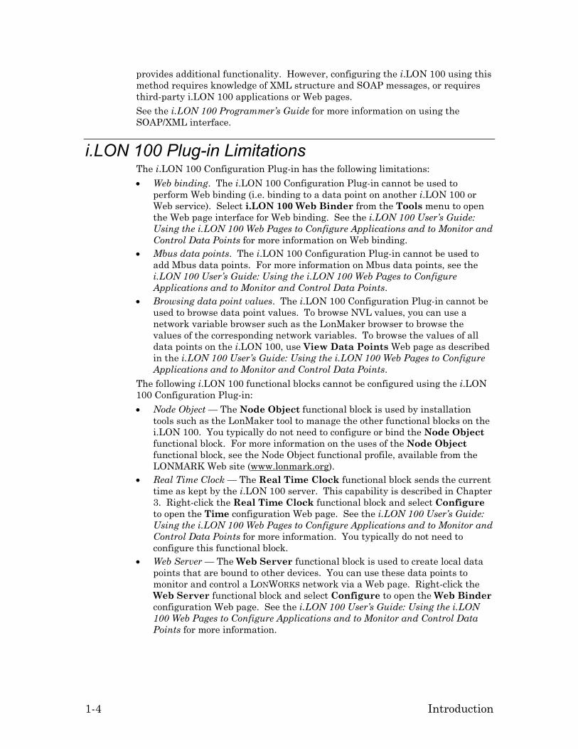
i.LON 100 Plug-in Limitations The i.LON 100 Configuration Plug-in has the following limitations: • Web binding. The i.LON 100 Configuration Plug-in cannot be used to
perform Web binding (i.e. binding to a data point on another i.LON 100 or Web service). Select i.LON 100 Web Binder from the Tools menu to open the Web page interface for Web binding. See the i.LON 100 User’s Guide: Using the i.LON 100 Web Pages to Configure Applications and to Monitor and Control Data Points for more information on Web binding.
• Mbus data points. The i.LON 100 Configuration Plug-in cannot be used to add Mbus data points. For more information on Mbus data points, see the i.LON 100 User’s Guide: Using the i.LON 100 Web Pages to Configure Applications and to Monitor and Control Data Points.
• Browsing data point values. The i.LON 100 Configuration Plug-in cannot be used to browse data point values. To browse NVL values, you can use a network variable browser such as the LonMaker browser to browse the values of the corresponding network variables. To browse the values of all data points on the i.LON 100, use View Data Points Web page as described in the i.LON 100 User’s Guide: Using the i.LON 100 Web Pages to Configure Applications and to Monitor and Control Data Points.
The following i.LON 100 functional blocks cannot be configured using the i.LON 100 Configuration Plug-in: • Node Object — The Node Object functional block is used by installation
tools such as the LonMaker tool to manage the other functional blocks on the i.LON 100. You typically do not need to configure or bind the Node Object functional block. For more information on the uses of the Node Object functional block, see the Node Object functional profile, available from the LONMARK Web site (www.lonmark.org).
• Real Time Clock — The Real Time Clock functional block sends the current time as kept by the i.LON 100 server. This capability is described in Chapter 3. Right-click the Real Time Clock functional block and select Configure to open the Time configuration Web page. See the i.LON 100 User’s Guide: Using the i.LON 100 Web Pages to Configure Applications and to Monitor and Control Data Points for more information. You typically do not need to configure this functional block.
• Web Server — The Web Server functional block is used to create local data points that are bound to other devices. You can use these data points to monitor and control a LONWORKS network via a Web page. Right-click the Web Server functional block and select Configure to open the Web Binder configuration Web page. See the i.LON 100 User’s Guide: Using the i.LON 100 Web Pages to Configure Applications and to Monitor and Control Data Points for more information.
i.LON 100 Internet Server User’s Guide 1-5
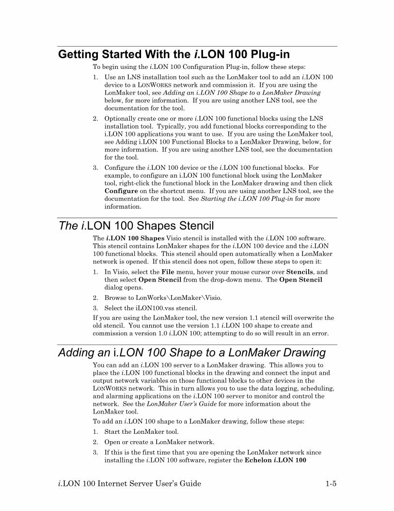
Getting Started With the i.LON 100 Plug-in To begin using the i.LON 100 Configuration Plug-in, follow these steps: 1. Use an LNS installation tool such as the LonMaker tool to add an i.LON 100
device to a LONWORKS network and commission it. If you are using the LonMaker tool, see Adding an i.LON 100 Shape to a LonMaker Drawing below, for more information. If you are using another LNS tool, see the documentation for the tool.
2. Optionally create one or more i.LON 100 functional blocks using the LNS installation tool. Typically, you add functional blocks corresponding to the i.LON 100 applications you want to use. If you are using the LonMaker tool, see Adding i.LON 100 Functional Blocks to a LonMaker Drawing, below, for more information. If you are using another LNS tool, see the documentation for the tool.
3. Configure the i.LON 100 device or the i.LON 100 functional blocks. For example, to configure an i.LON 100 functional block using the LonMaker tool, right-click the functional block in the LonMaker drawing and then click Configure on the shortcut menu. If you are using another LNS tool, see the documentation for the tool. See Starting the i.LON 100 Plug-in for more information.
The i.LON 100 Shapes Stencil The i.LON 100 Shapes Visio stencil is installed with the i.LON 100 software. This stencil contains LonMaker shapes for the i.LON 100 device and the i.LON 100 functional blocks. This stencil should open automatically when a LonMaker network is opened. If this stencil does not open, follow these steps to open it: 1. In Visio, select the File menu, hover your mouse cursor over Stencils, and
then select Open Stencil from the drop-down menu. The Open Stencil dialog opens.
2. Browse to LonWorks\LonMaker\Visio. 3. Select the iLON100.vss stencil. If you are using the LonMaker tool, the new version 1.1 stencil will overwrite the old stencil. You cannot use the version 1.1 i.LON 100 shape to create and commission a version 1.0 i.LON 100; attempting to do so will result in an error.
Adding an i.LON 100 Shape to a LonMaker Drawing You can add an i.LON 100 server to a LonMaker drawing. This allows you to place the i.LON 100 functional blocks in the drawing and connect the input and output network variables on those functional blocks to other devices in the LONWORKS network. This in turn allows you to use the data logging, scheduling, and alarming applications on the i.LON 100 server to monitor and control the network. See the LonMaker User’s Guide for more information about the LonMaker tool. To add an i.LON 100 shape to a LonMaker drawing, follow these steps: 1. Start the LonMaker tool. 2. Open or create a LonMaker network. 3. If this is the first time that you are opening the LonMaker network since
installing the i.LON 100 software, register the Echelon i.LON 100

1-6 Introduction
Configuration Plug-in and the Echelon i.LON 100 Web Server Plug-in in the Plug-in Registration window (see the LonMaker User’s Guide).
4. Drag the i.LON 100 FTT shape (for the free topology model) or i.LON 100 PL shape (for the power line model) from the i.LON 100 Shapes stencil to the LonMaker drawing. The New Device Wizard appears.
5. Step through the New Device Wizard. If your i.LON 100 server is connected to the network, you can commission it just like any other LONWORKS device. If you create any new network variables on any of the i.LON 100 functional blocks, you must commission the i.LON 100 device to add the new network variables to the i.LON 100 hardware. NOTE: If you have trouble commissioning the device on a power line channel due to inability to communicate with the device, you should increase the LonMaker Transmit Timer to at least 512 ms; to do this, open the LonMaker menu, click Network Properties, select the Timing tab, and then set this property.
Adding i.LON 100 Functional Blocks to a LonMaker Drawing
Once you have added the i.LON 100 shape to the LonMaker drawing, as described above, you can add i.LON 100 functional blocks. The functional blocks supported by the i.LON 100 server are contained in the i.LON 100 Shapes stencil (see Chapters 3 through 9 for more information on these shapes). Drag an i.LON 100 functional block shape to the LonMaker drawing in order to add it to the network design. See the LonMaker User’s Guide for more information on adding functional blocks and creating network variable shapes.
Starting the i.LON 100 Plug-in To start the i.LON 100 configuration plug-in,, follow these steps: 1. Select an i.LON 100 device or functional block as required by your LNS
installation tool and then start the plug-in. For example, if you are using the LonMaker tool, select an i.LON 100 device or functional block shape and then click Configure on the shortcut menu. The Specify i.LON 100 Configuration Data Source dialog appears, as shown in the following figure:

i.LON 100 Internet Server User’s Guide 1-7
2. Enter the IP address of the i.LON 100 server in TCP/IP Address. If you have configured the i.LON 100 to use a port other than 80, you must also specify the port (i.e. 192.168.1.222:8080).
3. Click OK. Note: You must be in both TCP/IP and LONWORKS network communication with the i.LON 100 server in order to configure it using the i.LON 100 Configuration Plug-in. The i.LON 100 should always be in sync with the LONWORKS application that opens it (i.e. in the LonMaker tool, you should be connected and OnNet). Note: The i.LON 100 device must be commissioned and online and the LonMaker tool must be attached to the network with the i.LON 100 in order to use the i.LON 100 Configuration Plug-in.
Organization of the i.LON 100 Plug-in The i.LON 100 Configuration Plug-in is organized into two main tabs, the Data Points tab and the Applications tab. You can use the Data Points tab to create and configure local, external, and constant data points. See Chapter 2 for more information. You can use the Applications pane to create and configure i.LON 100 functional blocks. See, The Applications Pane, below, for more general information about the Applications pane, and chapters 3 through 9 for more information on specific applications.
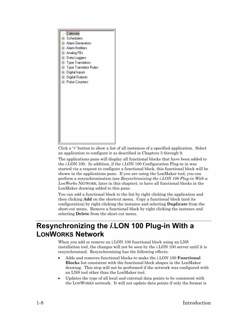
The Applications Pane The Applications tab of the i.LON 100 Configuration Plug-in contains the Functional Blocks list, as shown in the following figure:
1-8 Introduction
Click a ‘+’ button to show a list of all instances of a specified application. Select an application to configure it as described in Chapters 3 through 9. The applications pane will display all functional blocks that have been added to the i.LON 100. In addition, if the i.LON 100 Configuration Plug-in in was started via a request to configure a functional block, this functional block will be shown in the applications pane. If you are using the LonMaker tool, you can perform a resynchronization (see Resynchronizing the i.LON 100 Plug-in With a LonWorks NETWORK, later in this chapter), to have all functional blocks in the LonMaker drawing added to this pane. You can add a functional block to the list by right clicking the application and then clicking Add on the shortcut menu. Copy a functional block (and its configuration) by right-clicking the instance and selecting Duplicate from the short-cut menu. Remove a functional block by right clicking the instance and selecting Delete from the short-cut menu.
Resynchronizing the i.LON 100 Plug-in With a LONWORKS Network
When you add or remove an i.LON 100 functional block using an LNS installation tool, the changes will not be seen by the i.LON 100 server until it is resynchronized. Resynchronizing has the following effects: • Adds and removes functional blocks to make the i.LON 100 Functional
Blocks list consistent with the functional block shapes in the LonMaker drawing. This step will not be performed if the network was configured with an LNS tool other than the LonMaker tool.
• Updates the type of all local and external data points to be consistent with the LONWORKS network. It will not update data points if only the format is

i.LON 100 Internet Server User’s Guide 1-9
different. If the type of a data point changes, all preset information, including the default value, will be lost (see Data Point Presets in Chapter 2).
• Adds data point references to the functional blocks; e.g. if you add input network variables to the Data Logger functional block, the corresponding data points will be added to the Data Logger configuration page of the i.LON 100 Configuration Plug-in. This step will not be performed if the network was configured with an LNS tool other than the LonMaker tool.
• If you removed any network variables from the i.LON 100, they will optionally be reported. You can remove the associated data points from the i.LON 100 using the Delete button on the Data Points: Properties tab.
• If any functional blocks refer to data points that are no longer defined (i.e. the corresponding network variable has been removed), they will be reported. To have these data points automatically removed, set Remove Invalid Data Points From the i.LON 100 as described below.
To resynchronize the i.LON 100 server with a LonMaker drawing, follow these steps: 1. Click the Tools menu and then select Resync. Note that in version 1.0 of the
i.LON software, the resynchronization feature was accessible through a button on the lower part of the dialog.
2. Optionally click Options to open the following dialog:
Set the following options: Delete Application Instances Not Defined in LonMaker
If you are using the i.LON 100 Configuration Plug-in with the LonMaker tool, set this option to have the resynchronization delete all functional blocks that do not have corresponding functional block shapes in the LonMaker network. If there are i.LON 100 functional blocks that do not have corresponding LonMaker functional block shapes, resynchronizing with this option set will cause those functional blocks to be removed, along with all configuration. This option is set by default.
Remove Invalid Data Points From the i.LON 100
Set this option to have any invalid data points (i.e. data points that can no longer access their associated network variable) removed as part of the resynchronization. This option is not set by default.
Clear References to Invalid Data Points
Set this option to have any references to invalid data points removed as part of the resynchronization. This option is not set by

1-10 Introduction
default.
3. Click Go to begin the resynchronization. The dialog lists the changes that will be made to the i.LON 100 server’s configuration data. Review the changes.
4. Click Apply to accept the changes and update the i.LON 100 server and the i.LON 100 Configuration Plug-in. Click Continue to accept the changes and update the Configuration Plug-in, but not the i.LON 100 server; the i.LON 100 server will be updated when you click the OK or Apply button in the i.LON 100 Configuration Plug-in. Click Cancel to reject the changes.
NOTE: If, after performing a resynchronization using the i.LON 100 Configuration Plug-in, you subsequently delete the network using a tool other than the LonMaker tool, you must manually delete the network folder and all subfolders. The resynchronization process creates a folder (\iLonXml) below the network folder and a resynchronization log that are not removed when the network is deleted (this folder is also created by the backup and upgrade procedures described later in this chapter). The LonMaker tool will ask you whether you want to remove these folders as part of the network deletion process. If you do not remove these files, you will not be able to create a new network of the same name as the deleted one.
Setting i.LON 100 Plug-in Options To set i.LON 100 Configuration Plug-in options, open the Tools menu and select Options. The following dialog opens:
Set the following options:
Always Prompt for i.LON 100 IP Address
Set this option to always have the Specify i.LON 100 Configuration Data Source dialog appear when you start the i.LON 100 Configuration Plug-in. If the i.LON 100 is not commissioned or you are not OnNet, this dialog will appear irrespective of how this option is set.
Indicate Modified Applications
Set this option to have an asterisk appear next to applications in the Applications list when they have been modified but the changes have not been

i.LON 100 Internet Server User’s Guide 1-11
applied (i.e. you have not clicked the Apply or OK buttons).
Cache i.LON 100 XML Files Locally
Check this option to have i.LON 100 XML files cached locally. These files will be stored in the iLON100Xml folder in the LonWorks database folder for the LonWorks database that contains the i.LON 100.
Show Application’s LonMark Index
Set this option to have the functional block numbers appear for each functional block in the Applications list.
Show Application’s Index
Set this option to have the application indices for each functional block appear in the Applications list.
Show All FBs on External Points Page
Set this option to see all functional blocks on all devices when creating an external data point when starting the i.LON 100 Configuration Plug-in from the LonMaker tool. If this option is cleared, only the functional blocks that have been added to the LonMaker drawing will be shown. If the i.LON 100 Configuration Plug-in is started from another LNS application, you will always see all functional blocks on all devices when creating an external data point. This option is cleared by default.
Show Data Points For Undefined Applications
Set this option to have the Data Points:Properties tab show all NVL data points, regardless of whether the associated functional block has been created on the i.LON 100.
Control Width Resizes the i.LON 100 Configuration Plug-in window. Any change to this option will not take effect until the i.LON 100 Configuration Plug-in is closed and restarted.
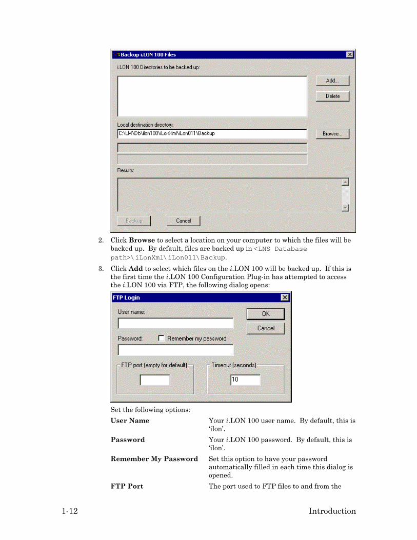
Backing Up the i.LON 100 Server You can backup the configuration of an i.LON 100 device using the i.LON 100 Configuration Plug-in or using FTP as described in the i.LON 100 User’s Guide: Installing, Connecting, and Configuring the i.LON 100. To backup the i.LON 100 using the plug-in, follow these steps: 1. Click the Tools menu and select Backup i.LON 100. The following window
opens:
1-12 Introduction
2. Click Browse to select a location on your computer to which the files will be
backed up. By default, files are backed up in <LNS Database path>\iLonXml\iLon011\Backup.
3. Click Add to select which files on the i.LON 100 will be backed up. If this is the first time the i.LON 100 Configuration Plug-in has attempted to access the i.LON 100 via FTP, the following dialog opens:
Set the following options: User Name Your i.LON 100 user name. By default, this is
‘ilon’. Password Your i.LON 100 password. By default, this is
‘ilon’. Remember My Password Set this option to have your password
automatically filled in each time this dialog is opened.
FTP Port The port used to FTP files to and from the

i.LON 100 Internet Server User’s Guide 1-13
i.LON 100. Leave this field blank to use the default FTP port.
Timeout The time, in seconds, after which the i.LON 100 Configuration Plug-in will stop trying to gain FTP access to the i.LON if no connection has been established.
Once you have provided this information, click OK. 4. The following dialog opens:
Use this dialog to select the directories that will be backed up. Once you have finished selecting files and directories to backup, click OK. To not back up a directory that you chose from the FTP list, select it from the i.LON 100 Directories to be Backed Up list and click Delete.
5. Click Backup. The i.LON 100 will FTP the files to the selected location on your computer. The status of the backup procedure will be displayed in Results. Click Cancel to cancel the backup procedure.
Using the i.LON 100 Configuration Plug-in With Version 1.0 of the i.LON 100 Firmware
You can use the i.LON 100 version 1.1 i.LON 100 Configuration Plug-in to access i.LON 100 servers running either version 1.0 or 1.1 firmware. Using the version 1.0 firmware with the version 1.1 Configuration Plug-in has the following capabilities and restrictions: • You can add, remove, and configure version 1.0 functional blocks using the
version 1.1 software. You can use the i.LON 100 Upgrade Wizard (described below) to automatically upgrade your version 1.0 firmware to version 1.1 with minimal disturbance to your configuration. Note that when you add a new Node Object functional block to a version 1.0 i.LON 100, you must use the

1-14 Introduction
generic Functional Block shape from LonMaker instead of the Node Object shape from the i.LON 100 Shapes 1.1 stencil.
• If you are using the LonMaker tool, the new version 1.1 i.LON 100 stencil will overwrite the old i.LON 100 stencil. You cannot add a new version 1.0 i.LON 100 device to a network using the version 1.1 stencil (though you may continue using an existing version 1.0 i.LON 100 as described above).
• If you have an existing network with version 1.0 i.LON 100 devices, you can create new version 1.0 i.LON 100 device shapes by copying existing version 1.0 device shapes. The version 1.1 functional block shapes in the stencil will work with the 1.0 device shape and the version 1.1 i.LON 100 Configuration Plug-in will be used to configure all i.LON 100 device shapes.
• When using a version 1.0 i.LON 100, if you configure a Web Server functional block, the LonMaker Browser will launch. In version 1.1, the Web Binder configuration Web page opens.
• If using the LonMaker tool, you can upgrade a version 1.0 i.LON 100 device shape by right-clicking it and selecting Upgrade from the short-cut menu. All functional blocks will be preserved, but any connections to the nvoDeviceAlarm output network variable on the Node Object functional block will be deleted and must be recreated.
• Before upgrading the i.LON 100 from version 1.0 to 1.1 you should back up all Data Logs and Alarm Logs via FTP. All logs will be deleted when the i.LON 100 boots for the first time using version 1.1.
• Data Logs and Alarm Logs, which use the CSV extension (text format), now use a comma ' , ' to separate data instead of a semi-colon ' ; '. If you have built a tool to read these logs via FTP, please make a note of this change and modify your tool to accommodate this new format when upgrading to version 1.1.
Upgrading the i.LON 100 Firmware Using the i.LON 100 Upgrade Wizard
To upgrade your i.LON 100 firmware from version 1.0 to version 1.1, follow these steps: 1. In the i.LON 100 Configuration Plug-in, open the Tools menu and select
Upgrade i.LON 100. The i.LON 100 Upgrade Wizard opens, as shown in the following figure:

i.LON 100 Internet Server User’s Guide 1-15
2. Click Next. The i.LON 100 Upgrade Options window opens, as shown in
the following figure:
Set the following options: Remove Obsolete Version 1.0 Files When the Upgrade is Complete
Set this option to have files which are not used in the version 1.1 i.LON 100 software removed once the upgrade has completed. Clearing this option will require an additional 3.5MB of disk space on the i.LON 100. This option should

1-16 Introduction
only be cleared if you intend to revert to firmware version 1.0 after the upgrade (this is not supported by the upgrade utility and you must perform the reversion manually using an FTP client). This option is set by default.
Backup Configuration Data Before Starting Upgrade
Set this option to have the config and ltConfig directories backed up to your computer before the upgrade procedure begins. This allows you to recover your configuration if the upgrade fails. The files will be backed up to the folder selected in the i.LON 100 Backup Folder window of the upgrade wizard. This option is set by default.
Update Type Translator Rule Definitions
Set this option to have the predefined Type Translator rules updated. If you made changes to the version 1.0 Type Translator rules using the SOAP interface, clear this option to preserve those changes after the upgrade. Any new rules you may have written will be unaffected by the upgrade. This option is set by default.
Update NVL Data Point Definitions
Set this option to have existing NVL data point definitions updated. This will update the NVL data point location strings to be compatible with the current Web pages. Setting this option will delete any preset values you have created for NVL data points. This option is set by default.
3. Click Next. If your i.LON 100 has insufficient disk spade to complete the upgrade, the following window opens (otherwise, skip to the next step):

i.LON 100 Internet Server User’s Guide 1-17
This window displays a tree view of the i.LON 100 directory structure. KB Required shows how much memory must be free, and KB Available shows how much memory is currently available. Browse the i.LON 100 directory structure and select files to be deleted until KB Available is greater than KB Required. If you have cleared the Remove Obsolete Version 1.0 Files When the Upgrade is Complete in the previous step, setting it will free up about 3.5MB of disk space.
4. Click Next. If you set the Backup Configuration Data Before Starting Upgrade option in the Upgrade Options window or selected files to be backed up in the Available Disk Space window, the i.LON 100 Backup Folder window opens as shown in the following figure (otherwise, skip to the next step):

1-18 Introduction
Set the path where the i.LON 100 data will be backed up before the upgrade procedure begins. By default, this path is <LNS Database path>\iLonXml\iLon011\Backup.
5. Click Next. The i.LON 100 Upgrade Status window opens, as shown in the following figure:
6. Click Start Upgrade to begin the upgrade. The following dialog opens:

i.LON 100 Internet Server User’s Guide 1-19
Set the following options: User Name Your i.LON 100 user name. By default, this is
‘ilon’. Password Your i.LON 100 password. By default, this is
‘ilon’. Remember My Password Set this option to have your password
automatically filled in each time this dialog is opened.
FTP Port The port used to FTP files to and from the i.LON 100. Leave this field blank to use the default FTP port.
Timeout The time, in seconds, after which the i.LON 100 Configuration Plug-in will stop trying to gain FTP access to the i.LON 100 if no connection has been established.
7. Click OK. The i.LON 100 Upgrade Status window will show the status of the upgrade. If an error occurs during the upgrade, repeat the upgrade procedure; when prompted, indicate that you wish to Resume (as opposed to Restart) the upgrade.
8. Once the upgrade has finished, the following dialog opens:
Click Launch IE to open Internet Explorer with the Reboot Web page selected. Once you have rebooted the i.LON 100, click OK.
9. Click Finish to close the wizard.
Upgrading the i.LON 100 Device Once you have finished upgrading the i.LON 100 firmware, you must upgrade the i.LON 100 device in the LNS database. See the documentation for your LNS tool for more information. If you are using the LonMaker tool, follow these steps:

1-20 Introduction
1. In the LonMaker tool, right-click the i.LON 100 device shape and select Replace from the short-cut menu.
2. When prompted for the device template, select the v12 version of the i.LON 100 template (FTT or PL)
3. When prompted for the Neuron ID, select Manual Entry. The default Neuron ID will be the current value and does not need to be changed.
4. Once the upgrade procedure is completed, the LonMaker tool upgrades the i.LON 100 device in the LNS database. If you had any connections to the nvoDeviceAlarm NV on the Node Object, those connections will be removed and have to be recreated.
i.LON 100 Internet Server User’s Guide 2-1
2
Data Points
This chapter describes how to add, remove, and view data points on the i.LON 100 Internet Server. Each data point represents a network variable value on the network that an i.LON functional block can get or set.

2-2 Data Points
Data Points The i.LON 100 server’s functional blocks and supporting applications are structured as diagrammed in the following figure:
Those familiar with other LONWORKS products are accustomed to thinking in terms of network variables. The i.LON 100 works with network variables, and also works with data elements from other field busses. For example, an i.LON 100 Scheduler functional block can schedule an ABCBus register just as easily as it can schedule a LonWorks network variable. This flexibility uniquely positions the i.LON 100 to integrate legacy devices from other field busses. Release 1.1 of the i.LON 100 applications includes NVL, NVE, NVC, and MBus drivers. Please contact Echelon support ([email protected]) directly for information on other third-party field bus drivers. The integration of other field busses with a LONWORKS network is accomplished by the i.LON 100’s data server. The data server is a software component that abstracts any data element of any bus into a data point. The i.LON 100’s functional blocks (Scheduler, Data Logger, Alarm Generator, etc.) operate on data points—not just network variables. When you use the i.LON 100 with LONWORKS devices, you can consider a data point to be the same thing as a network variable because a network variable is a LONWORKS data point. The i.LON 100 server can support up to 800 data points.
Data Point Types The i.LON 100 firmware supports the following data points types: local data points (also called NVL data points), external data points (also called NVE data points), constant data points (also called NVC data points), and Meter Bus data points (also called MBus data points):

i.LON 100 Internet Server User’s Guide 2-3
Local data points correspond to network variables that are defined locally on the i.LON 100 server. This includes any default network variables on an i.LON 100 functional block, and any network variables you might add to an i.LON 100 functional block. Local data points must be bound to one or more network variables on other devices in order to send or receive information on the LONWORKS network. External data points correspond to network variables on other LONWORKS devices. These data points are not implemented as network variables on the i.LON 100, instead the i.LON 100 polls or explicitly updates these network variables. The i.LON 100 server’s NVE driver keeps an XML file that contains all the information required to read and write external data points. This XML file is updated when you create NVE points using the i.LON 100 Configuration Plug-in. You can also write to this XML file manually; see the i.LON 100 Programmer’s Reference for more information. Because NVE points are explicitly polled or updated they consume no network variable resources on the referenced devices but often at the expense of increased network traffic. Constant data points are not associated with a network variable and are used to hold constant values. Constants are useful when making comparisons (for example, testing for alarm conditions) and when you need to supply a static value to some other device on your network. Meter Bus data points are used to communicate with Meter Bus (MBus) devices using the MBus protocol (EN 1434-3). MBus devices are connected to the i.LON 100 via the Serial Port. For more information on creating MBus data points, see the i.LON 100 User’s Guide: Using the i.LON 100 Web Pages to Configure Applications and to Monitor and Control Data Points.
Creating and Viewing Data Points You can create and view local data points, external data points, constant data points, and MBus data points.
Creating and Viewing Local Data Points (NVLs) You can create a local data point on an i.LON 100. These include all network variables included with the i.LON 100 and all network variables that you add. You can use any LNS installation tool that provides the capability to add dynamic network variables. For example, you can use the LonMaker tool to add dynamic network variables. See the LonMaker User’s Guide for more information on creating dynamic network variables. Note: The LonMaker tool maintains private information in the Description property of dynamic network variables. It is recommended that this property not be modified by any tools other than the LonMaker tool or the LonMaker browser. You can manage all local data points on functional blocks that have been defined on an i.LON 100 server using the i.LON 100 Configuration Plug-in. To view local data points (NVLs), follow these steps: Start the i.LON 100 plug-in as described in Starting the i.LON 100 Plug-in in Chapter 1. The following dialog appears:

2-4 Data Points
This tab displays all of the data points that exist on defined functional blocks on the selected i.LON 100 server. Local data points are created for all network variables on i.LON 100 functional blocks in the LONWORKS network, as well as all network variables on the Real Time Clock and Node Object functional blocks, which cannot be configured using the i.LON 100 Configuration Plug-in. If a dynamic data point is created on an i.LON 100 functional block while the i.LON 100 Configuration Plug-in is running, an associated NVL data point will be created once a resynchronization is performed (see Resynchronizing the i.LON 100 Plug-in With a LonWorks NETWORK, in Chapter 1). The Delete button can be used to remove NVL data points that no longer have an associated network variable. This can happen if you remove a network variable from the LonWorks network and then resynchronize the i.LON 100 Configuration Plug-in The name of a local data point is NVL_<network variable programmatic name>. Using the LonMaker tool, you can find the programmatic name of a network variable by right-clicking the network variable shape, selecting Properties from the shortcut menu to open the Network Variable Properties dialog, and reading the Programmatic Name field of the Description tab. The programmatic name may not be the same as the network variable name. See Network Variable Programmatic Names, below, for more information. You can sort the data points on this tab by clicking any of the column headings, just as you would in Windows Explorer. You can resize any of the columns by dragging the edges of the column header.
Network Variable Programmatic Names The network variable programmatic name is used to determine the name of the associated local data point. All programmatic network variable names on a device must be unique. For the network variables that are included with the i.LON 100, as well as any network variables that you create on an i.LON 100 using the LonMaker tool, the following rules are used to make the names unique: • For a static network variable (i.e. a network variable included with the i.LON
100) on arrays of functional blocks, the programmatic network variable name is: <NV name>[<FB array index>]

i.LON 100 Internet Server User’s Guide 2-5
<NV name> is the name of the network variable as it appears on the functional block. <FB array index> is the index of the functional block within the array. For example, the nviAnEnable network variable on the Alarm Notifier[4] functional block has a programmatic name of nviAnEnable[4]; the associated local data point is NVL_nviAnEnable[4].
• For a dynamic network variable (i.e. a network variable that you create), the programmatic network variable name is: NVname_FBindex NVname is the name of the network variable as it appears on the functional block. FBindex is the 3-digit functional block index of the functional block on which the network variable appears. Each functional block on a device has a unique functional block index. For example, if you drag an Alarm Notifier shape to your LonMaker drawing and associate it with Alarm Notifier[1], an nviAnAlarm network variable is dynamically created. This network variable will have a programmatic name of nviAnAlarm_097. 097 is the functional block index of Alarm Notifier[1] on the i.LON 100 device. The associated local data point is NVL_nviAnAlarm_097.
Do not change the programmatic names of the i.LON 100 network variables.
Creating and Viewing External Data Points (NVEs) You can create an external data point using the i.LON 100 Configuration Plug-in. An external data point is a data point associated with a network variable on another device. To create an external data point, follow these steps: 1. Start the i.LON 100 Configuration Plug-in as described in Starting the i.LON
100 Plug-in in Chapter 1. 2. Select the Data Points tab and then the External Points tab. The
External Points tab appears as shown in the following figure:

2-6 Data Points
3. Using the Network pane of this tab, set the check box to the left of one or more network variables to create external data points for them. If you set the check box next to a device or functional block, external data points will be created for each network variable on the device or functional block.
4. Click Add. The Specify Names for NVE Data Points dialog opens, as shown in the following figure:
5. Specify how the name(s) for the new data point(s) will be determined. You
can choose to use any or all of the following options: Include Device Name Set this option to include the device name in
the data point name. Include FB Name Set this option to include the functional block
name in the data point name. Include NV Name Set this option to include the network variable
name in the data point name. As you set and clear these options, you will see the results in the Name column. The format of the name is: NVE_[deviceName][fBlockName][nvName][index] An index will only be created if the options that you set are not sufficient to create a unique name for the new external data point; i.e. if you only set Include NV Name and you create external data points for two or more identically named network variables on different functional blocks. The name can have a maximum of 25 characters; if it is longer, it will be truncated. You can manually change the name of a data point by double-clicking the name. The name you specify must be unique and start with NVE_, any spaces and bracket characters (‘[‘ ‘]’) in the name will be removed, and any hyphens (‘-’) will be changed to underscores (‘_’).

i.LON 100 Internet Server User’s Guide 2-7
6. Click OK to create the new external data point(s). These data points will appear in External Data Points. They will all appear in the Properties tab.
Creating and Viewing Constant Data Points (NVCs) You can create a constant data point using the i.LON 100 Configuration Plug-in. A constant data point is useful when making comparisons—for example, testing for alarm conditions. A constant data point is also useful when you need to supply a static value to some other device on your network. To create a constant data point, follow these steps: 1. Start the i.LON 100 Configuration Plug-in as described in Starting the i.LON
100 Plug-in in Chapter 1. 2. Select the Data Points tab and then the Constants tab. The Constants
tab appears as shown in the following figure:
3. Click Add. The Set Data Point Format dialog appears as shown in the
following figure:

2-8 Data Points
4. Enter a name for the data point in Data Point Name. This field contains
NVC_ by default. 5. Select a network variable type and format for this constant. You can choose
from any data type that is available in the resource catalog. All available resources are displayed in a tree view. The top level of the tree shows all available resource files plus the built in data types. Expand the tree to view the resources within a resource file set. The selected resource files must be available on both the computer and on the i.LON 100. Resource files on the computer are maintained by the resource catalog. Resource files on the i.LON 100 are kept in /root/lonworks/types.
6. Click OK. The constant data point will be added to the Points list on the left side of the Constants tab.
7. Use the Data Point Presets tab to set the default value of this constant, as shown in the following figure:

i.LON 100 Internet Server User’s Guide 2-9
See Data Point Presets for more information.
Data Point Presets The i.LON 100 server allows you to define presets for each data point. For example you might define a preset named ON for an NVE_lampSw data point (which is defined as a SNVT_switch) as 100.0 1. You might also define a preset named ON for an NVL_heat_setpoint data point (which is of type SNVT_temp_f) to be 22. In both cases what you are saying is that you want to turn something on (lights or the heater), but the underlying data type needs to use 100.0 1 for lights and a floating point value of 22° C for the HVAC system. The data server in the i.LON 100 server allows you to abstract the idiosyncrasies of the data types and use a mnemonic (ON) that makes sense to a human. This makes it much easier to work with the point later on. Whenever you want to drive an output network variable to a pre-defined value you set the data point to a pre-defined preset. For example, to turn the lights on at 8:00AM a scheduler block sets the data point NVL_lampSw to the ON preset, and the data server automatically translates ON to 100.0 1 as it updates the output network variable. Another advantage of presets is that you can drive multiple outputs of different type simultaneously. For example, a scheduler can turn a group of points “ON” at 8:00AM, and if you included both the data points discussed above in the scheduled group the i.LON 100 server would send the value 22 on NVE_heat_setpoint at 8:00AM and 100.0 1 on NVL_lampSw at 8:00AM. This is an extremely powerful feature that allows the i.LON 100 server’s built-in applications to work with any kind of data type and field bus. This provides a layer of abstraction in the user interface so the end user does not need to know about the underlying data structures of the various data points. The i.LON 100 contains predefined presets for a number of data points. These presets can be viewed, modified, or removed using this tab just like any other presets.

2-10 Data Points
Creating Data Point Presets You can create predefined values for local, external, and constant data points. To create presets, follow these steps: 1. Start the i.LON 100 Configuration Plug-in as described in Starting the i.LON
100 Plug-in in Chapter 1. 2. Select the Data Points tab and then the Presets sub. The Presets tab
appears as shown in the following figure:
3. Select a data point from the Points list. If the selected data point is of a type
that has a predefined minimum, maximum, or invalid value, these values will appear in the Min, Max, and Invalid fields (see the resource file documentation for the data point type for more information—for standard LONMARK resource files, this information is available at types.lonmark.org; for user resource files, this information is provided by the resource file manufacturer. You can sort the data points on this tab by clicking any of the column headings, just as you would in Windows Explorer. You can resize any of the columns by dragging the edges of the column header.
4. If multiple formats are available for the data point type, set the format for the point. Click the button next to Format to open a dialog that allows you to select a format from all available resource files. Changing the type of a data point automatically changes the type of the corresponding network variable.
5. Optionally set a Default value. If this is a structure type data point, click the button to set each field separately. The Default value is used to set the data point value after a reboot or when the i.LON 100 server is put into override using a network tool; it cannot be referenced by the other i.LON 100 functional blocks like the custom values described below. Note: If an output data point has no default value (i.e. Default is <none>), it cannot send a heartbeat.

i.LON 100 Internet Server User’s Guide 2-11
6. To create additional presets for this data point, click Add. The Specify New Preset Name dialog appears, as shown in the following figure:
Enter the name of the new preset and click OK. The new preset name appears in the Custom Values list. Alternatively, you can double-click a Custom Values list entry and type preset names and values directly into the list.
7. Select the new preset name. If this data point is a structure-type data point, you can click Modify to set each field of the structure separately. Otherwise, click the Value column next to the preset name to enter a value that will correspond to the preset name.


i.LON 100 Internet Server User’s Guide 3-1
3
Managing Alarms
This chapter describes how to use the i.LON 100 Internet Server to define alarm conditions, how to trigger alarms, and how to clear alarms.

3-2 Managing Alarms
Alarming Overview The i.LON 100 Internet Server contains two types of functional blocks that control alarming—the Alarm Generator and the Alarm Notifier functional blocks. The alarm generator monitors one or more data point values and triggers alarms by setting a data point value when specified conditions are met. The alarm notifier monitors data points; it can be configured to respond to an alarm by modifying one or more data points, sending email, and/or logging the alarm. The i.LON 100 includes 40 of each type of alarm functional block. You can create, modify, and delete Alarm Generator and Alarm Notifier functional blocks using the i.LON 100 Configuration Plug-in or the i.LON 100 Web pages. These functional blocks are described in the following sections.
The Alarm Generator Functional Block The i.LON 100 includes 40 Alarm Generator functional blocks. An alarm generator generates alarms based on the values of any of the i.LON 100 data points. The alarm generator compares the values of an input data point with a compare data point each time either one is updated. You will select the function the alarm generator will use to make the comparison. If the result of the comparison is true, an alarm will be generated, and the status of the input data point will be updated to an alarm condition. For example, you could select a Greater Than comparison function. The alarm generator generates an alarm when either data point is updated and the value of the input data point is greater than the value of the compare data point. The alarm generator includes the following binary comparison functions: Less Than, Less Than or Equal, Greater Than or Equal, Equal, and Not Equal. The alarm generator also includes an analog comparison function. When you select this comparison function, you will specify four offset limits for the alarm generator. The four offset limits allow you to generate alarms based on how much the value of the input data point exceeds, or is exceeded by, the value of the compare data point. The alarm generator generates an alarm when either data point is updated and the difference between their values exceeds any of the offset limits. You will define a hysteresis level for each alarm-offset limit when you use the analog comparison function. After an alarm has been generated based on an offset limit, the value of the input data point must return to the hysteresis level defined for that offset limit before the alarm clears, and before another alarm can be generated based on that offset limit. As a result, the alarm generator will not generate an additional alarm each time the input data point is updated after it reaches an alarm condition, but before it has returned to a normal condition. All of the comparison functions have additional features that will allow you to throttle alarm generation. You can specify an interval that must elapse between alarm generations for a data point. You can also define an interval that must elapse after an alarm has returned to normal status before that alarm will be cleared. These features prevent the alarm generator from triggering multiple alarms each time the input data point reaches an alarm condition. You can optionally select up to two alarm data points for each alarm generator, one SNVT_alarm data point and one SNVT_alarm_2 data point. The status of these data points will be updated to an alarm condition each time the alarm generator state changes (i.e. passive to active or active to passive).

i.LON 100 Internet Server User’s Guide 3-3
The Alarm Generator functional block includes the following input and output network variables:
nviAgEnable This SNVT_switch static input network variable
enables and disables the alarm generator. If this network variable is set to Off (0.0 0), the alarm generator will not generate alarms. The default value for this network variable is On (100.0 1), so if this network variable is left unbound, the alarm generator will function normally.
nviAgLatchEnbl This SNVT_switch static input network variable can be used to latch an alarm. When this network variable is set to On (100.0 1) and an alarm is generated, the nvoAgAlarmFlag output will continue to send an On (100.0 1) value even when the conditions that caused the alarm no longer exist. When this network variable is set to Off (0.0 0), the nvoAgAlarmFlag network variable will be set to Off (0.0 0) when the alarm condition ends. See Latching, Acknowledging, and Clearing Alarms, later in this chapter, for more information.
nviAgInput This changeable-type input network variable provides an input value to the alarm generator. Typically, the alarm generator compares this value to the nviAgCompare network variable value to determine if an alarm should be generated. The comparison function can be configured as described in Configuring the Alarm Generator Functional Block, below.
nviAgCompare This dynamic changeable-type input network variable provides a value to be compared to the nviAgInput network variable value. This network variable must have the same type as the nviAgInput network variable.
nvoAgAlarmFlag This SNVT_switch static output network variable is set to Off (0.0 0) when no alarm is being generated and to On (100.0 1) when an alarm is generated.
nvoAgAlarm This SNVT_alarm dynamic output network variable sends alarms generated by the alarm generator. The SNVT_alarm network variable type is described in the standard resource file

3-4 Managing Alarms
documentation available from the LONMARK Web site at types.lonmark.org.
The Alarm Notifier Functional Block The i.LON 100 includes 40 Alarm Notifier functional blocks. An alarm notifier logs alarm conditions and generates email messages and data point updates each time an alarm condition occurs. You can use an alarm notifier to provide notification of alarms generated by any device that produces a SNVT_alarm or SNVT_alarm_2 output, including the i.LON 100 device itself. For example, you can use an alarm notifier to provide alarm notification of alarms produced by alarm generators on the i.LON 100 device. You can also use the alarm notifier to provide notification of any i.LON 100 data point going offline. You will specify a group of input data points for each alarm notifier. The alarm notifier reads the status of these data points each time they are updated to determine if the alarm condition for the point has been changed to a value other than AL_NO_CONDITION (you can limit this further using the Alarms tab, as described below). If the data point has such a condition, the alarm is classified as an active alarm and an alarm notification is generated. Each time an input data point is updated and the alarm condition is set to AL_NO_CONDITION, the alarm is classified as a passive alarm. You can specify one or more output data points for each alarm notifier. These data points will be updated each time an alarm notification occurs. You can also specify an email profile for each alarm notifier. An email message will be sent to the addresses specified for that email profile each time an alarm notification occurs. You can specify the message text, subject heading, and attachment to be included with each email notification. Email profiles allow you to notify different people when different alarms occur. This is useful if different groups of people need to receive notifications about the various alarm conditions that can occur on your network. See the i.LON 100 User’s Guide: Installing, Connecting, and Configuring the i.LON 100 for information on configuring the i.LON 100 to communicate with an email server. Each alarm notifier generates a log file. It will add an entry to this log file each time it causes an alarm notification. You can find these log files in the /root/AlarmLog directory of the i.LON 100 device. These files are named histlogX, where X represents the index number assigned to the alarm notifier when it was created. An alarm notifier will not generate a log file until it has generated an alarm notification. The i.LON 100 device does not limit how much alarm data can be logged. However, you should maintain at least 1024KB of free disk space. You can view the amount of free disk space using the System Info Web page. In addition, the alarm notifier generates a summary log that summarizes the log entries made by all alarm notifiers that were classified as active alarms. This file is called sumlog0, and can also be found in the /root/AlarmLog directory of your i.LON 100 device. The Alarm Notifier functional block includes the following input and output network variables:

i.LON 100 Internet Server User’s Guide 3-5
nviAnEnable A SNVT_switch type static input network
variable. This input network variable is used to enable and disable the Email and Outputs tabs (Configuring the Alarm Notifier Functional Blocks). Using the Configuration Plug-in, you can configure the alarm notifier to use other network variables as enable inputs.
nviAnAlarm This SNVT_alarm dynamic input network variable is used to receive SNVT_alarm type messages. How the Alarm Notifier functional block responds to these messages is configured using the Alarm Notifier tab of the i.LON 100 Configuration Plug-in, as described blow.
nvoAnAlmFlag This SNVT_switch dynamic output network variable is set to On (100.0 1) whenever an alarm notifier is responding to an alarm. When no alarm has been detected, this network variable is set to Off (0.0 0).
Configuring an Alarm Generator You can configure an Alarm Generator functional block to generate an alarm update in response to input conditions that you define. An alarm update from an alarm generator does not result in an alarm notification. To provide notifications of an alarm update, connect the alarm output of an alarm generator, or any other functional block with an alarm output, to one or more alarm notifiers (see Configuring the Alarm Notifier Functional Blocks, later in this chapter). You can configure an Alarm Generator functional block using either the i.LON 100 Configuration Plug-in or the Alarm Generator Configuration Web page. To configure an alarm generator to generate alarms using the i.LON 100 Configuration Plug-in, follow these steps: 1. Open an existing LonMaker network or create a new LonMaker network as
described in the LonMaker User’s Guide. 2. Use an existing i.LON 100 device in the LonMaker network, or create and
commission a new i.LON 100 device. 3. Define a data point to be monitored as described in Chapter 2. This is the
input data point. 4. Define a data point to use as a comparison value as described in Chapter 2.
This is the comparison data point. For example, you may define a constant data point to compare the input data point against.
5. Associate the Alarm Generator functional block shape with any of the available Alarm Generator functional blocks on the i.LON 100 device, and then click Next.

3-6 Managing Alarms
6. Enter a name for the Alarm Generator functional block, and then click Finish.
7. Right-click the Alarm Generator functional block, and then select Configure from the shortcut menu. Enter the IP address or fully qualified host name of the i.LON 100 server when prompted. The following tab appears:
8. Select the input and comparison data points from the Input Data Point and
Comparison Data Point lists. 9. Select a comparison function from the Comparison list between the input
and comparison data points. The available comparison functions include the following: • Input value deviates from comparison value. • Input value is equal to comparison value. • Input value is greater than comparison value. • Input value is greater than or equal to comparison value. • Input value is less than comparison value. • Input value is less than or equal to comparison value. • Input value is not equal to comparison value.
10. If you selected the Deviates From comparison function, enter High Limit, Deadband, and Low Limit values on the right side of the tab. Click Help for a description of these values.
11. Set Priority to a value from 0 to 11, with 0 being the highest priority and 11 being the lowest priority. This value will be sent in the priority field of the SNVT_alarm or SNVT_alarm_2 output.
12. Enter a description of the criteria in Description. This allows other network integrators to easily understand the purpose of this Alarm Generator functional block.
13. Select Output from below the Alarm Generator from Applications list. The following dialog appears:

i.LON 100 Internet Server User’s Guide 3-7
14. Select one or two output data points in Alarm Output Data Point and
Alarm2 Output Data Point. Use Alarm Output Data Point to select a SNVT_alarm output; use Alarm2 Output Data Point to select a SNVT_alarm_2 output.
15. You can optionally specify alarm timing in Alarm Timing Values. Set Poll Rate to a positive value if you have specified an external data point for either the input value or the comparison value. Click Help for a description of these values.
16. Click OK to configure the i.LON 100 device and close the plug-in, or click Apply to configure the i.LON 100 device without closing the plug-in.
Providing an Alarm Notification You can configure an Alarm Notifier functional block to provide a network or email notification of an alarm condition. The alarm condition may be generated by an Alarm Generator functional block, it may be generated by another LONWORKS device that produces SNVT_alarm or SNVT_alarm_2 alarm outputs, or it may be generated in response to any data point going offline. To configure an alarm notifier to provide alarm notifications, follow these steps: 1. Use an LNS installation tool such as the LonMaker tool to open an existing
network or create a new network as described in your installation tool documentation.
2. Use an existing i.LON 100 device in your network, or create and commission a new i.LON 100 device.
3. To provide email notifications, configure the i.LON 100 device to send email as described in the i.LON 100 User’s Guide: Installing, Connecting, and Configuring the i.LON 100.
4. Add an Alarm Notifier functional block to your network. For example, using the LonMaker tool drag an Alarm Notifier functional block shape

3-8 Managing Alarms
from the i.LON 100 Shapes stencil to the drawing. The New Functional Block wizard appears (the next 3 steps assume you are using the LonMaker tool).
5. Associate the Alarm Notifier functional block shape with any of the available Alarm Notifier functional blocks on the i.LON 100 device, and then click Next.
6. Enter a name for the Alarm Notifier functional block, and then click Finish.
7. Right-click the Alarm Notifier functional block and then select Configure from the shortcut menu. Enter the IP address or fully qualified host name of the i.LON 100 server when prompted. The following window appears:
8. Enter a description of the alarm notifier in Description. This allows other
network integrators to easily understand the purpose of this Alarm Notifier functional block.
9. Optionally set global options for this alarm notifier. Click Help for a description of the available options.
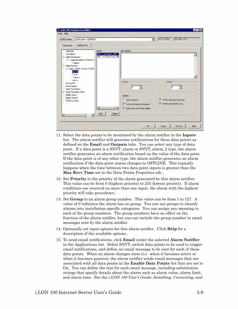
10. Click Inputs under the selected Alarm Notifier in the Applications list. The following tab appears:
i.LON 100 Internet Server User’s Guide 3-9
11. Select the data points to be monitored by the alarm notifier in the Inputs
list. The alarm notifier will generate notifications for these data points as defined on the Email and Outputs tabs. You can select any type of data point. If a data point is a SNVT_alarm or SNVT_alarm_2 type, the alarm notifier generates an alarm notification based on the value of the data point. If the data point is of any other type, the alarm notifier generates an alarm notification if the data point status changes to OFFLINE. This typically happens when the time between two data point inputs is greater than the Max Recv Time set in the Data Points Properties tab..
12. Set Priority to the priority of the alarm generated by this alarm notifier. This value can be from 0 (highest priority) to 255 (lowest priority). If alarm conditions are received on more than one input, the alarm with the highest priority will take precedence.
13. Set Group to an alarm group number. This value can be from 1 to 127. A value of 0 indicates the alarm has no group. You can use groups to classify alarms into installation-specific categories. You can assign any meaning to each of the group numbers. The group numbers have no effect on the function of the alarm notifier, but you can include the group number in email messages sent by the alarm notifier.
14. Optionally set input options for this alarm notifier. Click Help for a description of the available options.
15. To send email notifications, click Email under the selected Alarm Notifier in the Applications list. Select SNVT_switch data points to be used to trigger email notifications, and define an email message to be sent for each of these data points. When an alarm changes state (i.e. when it becomes active or when it becomes passive), the alarm notifier sends email messages that are associated with all data points in the Enable Data Points list that are set to On. You can define the text for each email message, including substitution strings that specify details about the alarm such as alarm value, alarm limit, and alarm time. See the i.LON 100 User’s Guide: Installing, Connecting, and
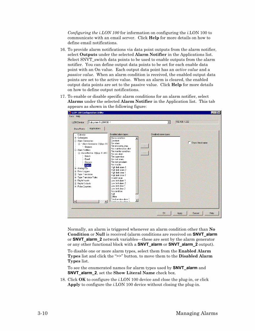
3-10 Managing Alarms
Configuring the i.LON 100 for information on configuring the i.LON 100 to communicate with an email server. Click Help for more details on how to define email notifications.
16. To provide alarm notifications via data point outputs from the alarm notifier, select Outputs under the selected Alarm Notifier in the Applications list. Select SNVT_switch data points to be used to enable outputs from the alarm notifier. You can define output data points to be set for each enable data point with an On value. Each output data point has an active value and a passive value. When an alarm condition is received, the enabled output data points are set to the active value. When an alarm is cleared, the enabled output data points are set to the passive value. Click Help for more details on how to define output notifications.
17. To enable or disable specific alarm conditions for an alarm notifier, select Alarms under the selected Alarm Notifier in the Application list. This tab appears as shown in the following figure:
Normally, an alarm is triggered whenever an alarm condition other than No Condition or Null is received (alarm conditions are received on SNVT_alarm or SNVT_alarm_2 network variables—these are sent by the alarm generator or any other functional block with a SNVT_alarm or SNVT_alarm_2 output). To disable one or more alarm types, select them from the Enabled Alarm Types list and click the “>>” button. to move them to the Disabled Alarm Types list. To see the enumerated names for alarm types used by SNVT_alarm and SNVT_alarm_2, set the Show Literal Name check box.
18. Click OK to configure the i.LON 100 device and close the plug-in, or click Apply to configure the i.LON 100 device without closing the plug-in.

i.LON 100 Internet Server User’s Guide 3-11
Scenario - Configuring an Alarm System The following example demonstrates how to design and configure a simple alarming application using the i.LON 100 Configuration Plug-in. The example is specific to a particular scenario, but the concepts can be used for any alarming application. If you need more information about a particular tab of the alarming configuration dialogs, click the Help button in the i.LON 100 Configuration Plug-in.
Description A water-piping system for a building in New York City uses an Alarm Generator functional block connected to a temperature sensor functional block on another device. The alarm generator compares the data point value from the temperature sensor with a constant data point value set to a temperature near freezing. This constant value represents the low-limit 2 value for the temperature. When the temperature falls below four degrees above the low-limit 2 value, the generator updates a SNVT_alarm data point. This is the low-limit 1 value. An Alarm Notifier functional block monitors this data point and when an alarm condition is set, it automatically turns on the heating mechanism to keep the pipes from freezing and sends an email to the building staff informing them of the alarm and the response. The alarm is logged in the i.LON 100’s internal alarm log. When the temperature returns to a safe level, the alarm is cancelled automatically. If the temperature continues to drop below the low-limit 2 value, the alarm generator functional block triggers a different, more serious alarm condition. A separate alarm notifier functional block then sends a more urgent email message reports this second alarm condition. This alarm notifier is configured so the alarm is not automatically cleared. It must be manually cleared using a Web page hosted by the i.LON 100.
Designing the LonMaker Network Drawing To use the LonMaker tool to create the example network described above, follow these steps: 1. Open an existing LonMaker network or create a new LonMaker network as
described in the LonMaker User’s Guide. 2. Use an existing i.LON 100 device in the LonMaker network, or create and
commission a new i.LON 100 device. 3. Configure the i.LON 100 device to send email as described in the i.LON 100
User’s Guide: Installing, Connecting, and Configuring the i.LON 100. 4. Drag an AI-10 LonPoint device shape from the LonPoint Shapes stencil to
the drawing. This LonPoint device will be physically attached to a temperature sensor. See the LonPoint Hardware Guide and LonPoint User’s Guide for more information.
5. Drag an Analog Input functional block shape from the LonPoints Shapes stencil to the drawing. Associate it with one of the Analog Sensor functional blocks on the AI-10 device. Name this shape Temperature Input.
6. Drag a DO-10 LonPoint shape from the LonPoint Shapes stencil to the drawing. This LonPoint will be physically attached to a heater control relay near the water pipes.

3-12 Managing Alarms
7. Drag a Digital Output shape from the LonPoint Shapes stencil to the drawing. Associate it with one of the Digital Output functional blocks on the DO-10 device. Name this shape Heater.
8. Drag an Alarm Generator functional block shape from the i.LON 100 Shapes stencil to the drawing. Associate it with any of the available Alarm Generator functional blocks on the i.LON 100 device. Name this shape Alarm Generator.
9. Drag two Alarm Notifier functional block shapes from the i.LON 100 Shapes stencil. Associate them with two Alarm Notifier functional blocks on the i.LON 100 server. Name these shapes Alarm Notifier – Warning and Alarm Notifier – Emergency.
10. Make the following network variable connections: • Connect the Analog output network variable on the Temperature Input functional block to the nviAgInput input network variable on the Alarm Generator functional block. • Connect the nvoAgAlarm output network variable on the Alarm Generator functional block to the nviAnAlarm input network variables on both the Alarm Notifier – Warning, and Alarm Notifier – Emergency functional blocks. • Connect the nvoAnAlarmFlag output network variable on the Alarm Notifier – Warning functional block to the Digital input network variable on the Heater functional block,
When you are done, your LonMaker drawing should look something like the following figure:
Creating a Constant Data Point In the scenario described above, we want to compare the value of the nviAgInput network variable to freezing to determine whether to generate an alarm. In order to do this, we will create a constant data point that contains the value for freezing as a value in degrees Celsius. To do this, follow these steps: 1. Right-click the i.LON 100 device shape and select Configure from the
shortcut menu. Enter the IP address or fully qualified host name of the i.LON 100 server when prompted. The i.LON 100 Configuration Plug-in opens.
2. Select the Data Points tab and the Constants sub-tab. 3. Click Add to create a new constant data point. The Set Data Point Type
dialog opens. 4. Choose STANDARD.FMT from the Type Files list, select SNVT_temp_f#SI
from the Type List, and set Data Point Name to NVC_freezing, as shown in the following figure:

i.LON 100 Internet Server User’s Guide 3-13
5. Click OK. The NVC_freezing data point appears in the Points list. 6. Select the Presets tab. 7. Select the NVC_freezing data point from the Points list. 8. Click the Default field and enter 0. Click Apply.
Configuring the Alarm Generator Functional Block To configure the Alarm Generator functional block, follow these steps: 1. Right-click the Alarm Generator functional block and select Configure from
the shortcut menu. The i.LON 100 Configuration Plug-in opens with the Alarm Generator configuration dialog selected.
2. Select the Alarm Generator window. 3. Select NVL_nviAgInput from Input Data Point list, Deviates From from
the second list, and NVC_freezing from the Comparison list. This causes the High Limits, Deadband, and Low Limits frames on the right side of the tab to become active. Note: Be sure that the NVL_nviAgInput data point is associated with the nviAgInput network variable on the Alarm Generator functional block. You can verify this using the Input Data Point list. The data points that are on the selected Alarm Generator functional block are listed first under Local Data Points.
4. Set the Enable Warning and Enable Error check boxes in Low Limits. This causes an alarm to be generated when the value of the Input Data Point passes below a certain point.
5. Set Offset 1 to –4. This causes an AL_LOW_LMT_ALM_1 alarm to be generated when the Input Data Point (i.e. the temperature) passes below 4 degrees. The value in this field is subtracted from the Comparison data point to determine when the alarm is generated; 0 – (-4) = 4.

3-14 Managing Alarms
6. Set Offset 2 to 0. This causes an AL_LOW_LMT_ALM_2 alarm to be generated when the Input data point passes below 0 degrees F (-18 degrees C).
7. Set the Deadband to 2. If one of the low limits is passed, the alarm condition will stay active until the Input Data Point is 2 degrees above the threshold. This prevents the heater from rapidly switching on and off as the temperature hovers around 4 degrees.
8. Set the Priority to 1. 9. Enter a description of the criteria in Description.
When you are finished, the Alarm Generator window appears as shown in the following figure:
10. Select the Output window from below the Alarm Generator. 11. Set Alarm Output Data Point to NVL_nvoAgAlarm. This data point is
associated with the nvoAgAlarm network variable on the Alarm Generator functional block (you should verify this as described in the note in step 3). The Output tab appears as shown in the following figure.
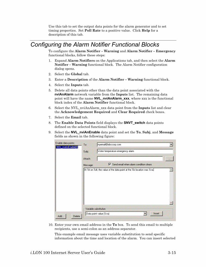
i.LON 100 Internet Server User’s Guide 3-15
Use this tab to set the output data points for the alarm generator and to set timing properties. Set Poll Rate to a positive value. Click Help for a description of this tab.
Configuring the Alarm Notifier Functional Blocks To configure the Alarm Notifier – Warning and Alarm Notifier – Emergency functional blocks, follow these steps: 1. Expand Alarm Notifiers on the Applications tab, and then select the Alarm
Notifier – Warning functional block. The Alarm Notifier configuration dialog opens.
2. Select the Global tab. 3. Enter a Description of the Alarm Notifier – Warning functional block. 4. Select the Inputs tab. 5. Delete all data points other than the data point associated with the
nviAnAlarm network variable from the Inputs list. The remaining data point will have the name NVL_nviAnAlarm_xxx, where xxx is the functional block index of the Alarm Notifier functional block.
6. Select the NVL_nviAnAlarm_xxx data point from the Inputs list and clear the Acknowledgement Required and Clear Required check boxes.
7. Select the Email tab. 8. The Enable Data Points field displays the SNVT_switch data points
defined on the selected functional block. 9. Select the NVL_nviAnEnable data point and set the To, Subj, and Message
fields as shown in the following figure:
10. Enter your own email address in the To box. To send this email to multiple
recipients, use a semi-colon as an address separator. This example email message uses variable substitution to send specific information about the time and location of the alarm. You can insert selected
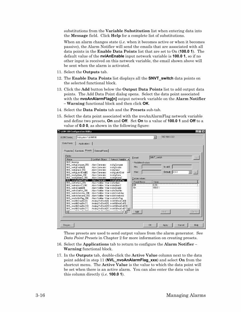
3-16 Managing Alarms
substitutions from the Variable Substitution list when entering data into the Message field. Click Help for a complete list of substitutions. When an alarm changes state (i.e. when it becomes active or when it becomes passive), the Alarm Notifier will send the emails that are associated with all data points in the Enable Data Points list that are set to On (100.0 1). The default value of the nviAnEnable input network variable is 100.0 1, so if no other input is received on this network variable, the email shown above will be sent when the alarm is activated.
11. Select the Outputs tab. 12. The Enable Data Points list displays all the SNVT_switch data points on
the selected functional block. 13. Click the Add button below the Output Data Points list to add output data
points. The Add Data Point dialog opens. Select the data point associated with the nvoAnAlarmFlag[n] output network variable on the Alarm Notifier – Warning functional block and then click OK.
14. Select the Data Points tab and the Presets sub-tab. 15. Select the data point associated with the nvoAnAlarmFlag network variable
and define two presets, On and Off. Set On to a value of 100.0 1 and Off to a value of 0.0 0, as shown in the following figure:
These presets are used to send output values from the alarm generator. See Data Point Presets in Chapter 2 for more information on creating presets.
16. Select the Applications tab to return to configure the Alarm Notifier – Warning functional block.
17. In the Outputs tab, double-click the Active Value column next to the data point added in step 11 (NVL_nvoAnAlarmFlag_xxx) and select On from the shortcut menu. The Active Value is the value to which the data point will be set when there is an active alarm. You can also enter the data value in this column directly (i.e. 100.0 1).

i.LON 100 Internet Server User’s Guide 3-17
18. Double-click the Passive Value column and select Off from the shortcut menu. The Passive Value is the value to which the data point will be set when there is no alarm. The Output tab should now appear as shown in the following figure:
When an alarm is activated, the NVL_nvoAnAlarmFlag_xxx data point will be set to On (100.0 1). When the alarm is cleared, the data point will be set to Off (0.0 0).
19. Expand Alarm Notifiers on the Applications tab, and then select the Alarm Notifier – Emergency functional block.
20. Select the Global tab. 21. Enter a Description of the Alarm Notifier – Emergency functional block. 22. Select the Inputs tab. 23. Clear the Acknowledgement Required check box. The Clear Required
check box should be set. 24. Select the Email tab. 25. Remove all data points from the Enable Data Points list other than
NVL_nviAnEnable[n]. 26. Select the NVL_nviAnEnable data point and set the To, Subj, and Message
boxes as shown in the following figure:

3-18 Managing Alarms
27. Enter your own email address in the To box. 28. Select the Alarms tab. 29. Select the AL_LOW_LMT_ALM_1 alarm type and clear the Enable Alarm
check box. This prevents the Alarm Notifier – Emergency functional block from registering an alarm when the first low limit is passed.
30. Click Apply.
Simulating an Alarm To simulate an alarm, follow these steps: 1. Right-click the Alarm Generator functional block and select Browse from the
shortcut menu. The LonMaker browser opens. 2. Click the Monitor All button on the toolbar. The browser starts monitoring
all points in the browser window, allowing you to see network variable value updates as they happen.
3. To simulate a warning level alarm, select the nviAgInput network variable,
enter a value of 3, and then click the Set Value button ( ). The i.LON 100 device updates the nvoAgAlarm output network variable to a condition of AL_LOW_LMT_ALM_1. Be sure that the browser is displaying the value of nviAgInput in SI units (i.e. Celsius).
4. Open a Web browser (Internet Explorer 6 or better) and point it to the IP address of your i.LON 100 server.
5. Click View under the Alarming heading. 6. Select Alarm Notifier – Warning from the Alarm Log list. The following
alarm appears at the bottom of the page:

i.LON 100 Internet Server User’s Guide 3-19
7. To simulate an emergency alarm, return to the LonMaker browser and set the nviAgInput value to -2. The i.LON 100 device updates the nvoAgAlarm output network variable to a condition of AL_LOW_LMT_ALM_2.
8. To simulate no alarm condition, set the nviAgInput value to 40. 9. Return to the Web browser and then click Clear on the left side of the Web
page. 10. Select Alarm Notifier – Emergency from the Alarm Log list. A new
alarm appears in the list at the bottom of the page. 11. Set the CLR check box and click Update Log to clear the alarm.
Detecting Heartbeat Failures You can use the Alarm Notifier functional block to detect heartbeat failures. To do this, follow these steps: 1. Drag an Alarm Notifier functional block shape from the i.LON 100 stencil
to the LonMaker drawing. 2. Determine what network variable will be monitored for heartbeat failure. If
the selected network variable has an associated external data point on the i.LON 100 device skip to step 4.
3. Connect the network variable to be monitored to the nviAnStatAlm input network variable on the Alarm Notifier functional block. You may need to change the type of the nviAnStatAlm network variable to do this.
4. Right-click the Alarm Notifier functional block created in step 1 and select Configure from the shortcut menu. Enter the IP address or fully qualified host name of the i.LON 100 server when prompted. The i.LON 100 Configuration Plug-in opens.
5. Select the Inputs tab. 6. Remove all input data points from the Inputs tab by selecting them and
clicking Delete. 7. Click Add and add the data point to be monitored for heartbeat failure. This
is either the external data point identified in step 2 or the NVL_nviAnStatAlm_xxx data point on the Alarm Notifier functional block.
8. When there is a heartbeat failure, the Alarm Notifier will register an AL_NUL alarm condition. Configure the Email and Output tabs to respond as desired.
Latching, Acknowledging, and Clearing Alarms In some situations, you may want an alarm to stay active even when the condition that caused the alarm has been returned to normal. One example of this is shown above, with the Alarm Notifier – Emergency alarm requiring a manual clear via the Web page. If a piece of hardware fails, causing an alarm that causes a backup piece of hardware to be activated, the alarm should stay active until manually cleared. The i.LON 100 server provides three ways of implementing this behavior: • Set the Clear Required check box on the Inputs tab of the Alarm Notifier
configuration dialog tab. This method is demonstrated in the example above.

3-20 Managing Alarms
Setting this check box causes the Alarm Notifier to maintain the alarm state until the alarm is cleared using the Alarm Summary Web page (see the help for these Web pages for more information). The condition that caused the alarm should be removed or the alarm will just immediately be regenerated. To clear the alarm, a user must have access to the Alarm Summary Web page. You can grant this access as described in the i.LON 100 User’s Guide: Using the i.LON 100 Web Pages to Configure Applications and to Monitor and Control Data Points.
• Set the Acknowledgement Required check box on the Inputs tab of the Alarm Notifier configuration dialog tab. Setting this check box causes the Alarm Notifier to maintain the alarm state until the alarm has been Acknowledged using the Alarm Summary Web page. An alarm can be acknowledged even while the alarm condition is still true; however, the Alarm Notifier will not terminate the alarm until the condition has been removed.
• Use the nviAgLatchEnable network variable on the Alarm Generator Functional Block. When this SNVT_switch network variable is set to On (100.0 1), the Alarm Generator’s nvoAgAlarmFlag network variable will remain set to On (100.0 1) even after the alarm condition has ended. Set this network variable to Off (0.0 0) to have the nvoAgAlarmFlag network variable reflect the state of the alarm.

i.LON 100 Internet Server User’s Guide 4-1
4
Logging Data
This chapter describes how to use the i.LON 100 Internet Server to save network data in data logs and how to view the data logs.

4-2 Logging Data
Data Logging Overview The i.LON 100 Internet Server contains 10 Data Logger functional blocks. To create a data log, create a Data Logger functional block in an LNS installation tool such as the LonMaker tool. To create a Data Logger functional block using the LonMaker tool, drag one of the Data Logger functional blocks to a LonMaker drawing. Then you use the i.LON 100 Configuration Plug-in to associate one or more data points with the Data Logger shape. You can use a data logger to record updates to a group of user-specified data points into a log file. The log files for each data logger are stored in the /root/Data directory of the i.LON 100 with the file name logX, where X represents the index number assigned to the data logger. You can create two kinds of data loggers: historical data loggers, and circular data loggers. A historical data logger stops recording data point updates when its log file becomes full. A circular data logger removes the records for older updates when its log file is full, and new updates occur. A data logger can save either type of log file in an ASCII-text (.csv file extension) or binary (.dat file extension) format. You will specify the minimum amount of time that must elapse, and the minimum change in value required, between log entries for each data point your data logger is monitoring. When an update to a data point is logged, a subsequent update for that data point will not be logged until the minimum time period specified for the data point has elapsed, and the minimum value change specified for the data point has been met. If any of the input data points are updated before the minimum time period and value change have elapsed, the older values will be discarded. The data logger records the most recent update when the minimum time period and value change elapse. This allows you to throttle the data entries into a log. You can also define a threshold level for each data logger. The threshold level represents a percentage. When the data logger’s log file consumes this percentage of the memory space allocated to it, the data logger provides notification that it is time to upload the log and clear out some of the data. The data logger makes this notification by updating the data logger’s alarm data point (called NVL_nvoDlAlarm[X], where X represents the index number assigned to the data logger) to the status AL_ALM_CONDITION. This feature is useful when working with historical data loggers, which are disabled when they become full. You can access the data in a log file by viewing it in the data logging Web page, by manually opening the log file, or by using a SOAP function. You can clear data from a log by sending an update to the data point NVL_nviDlClear[X], where X represents the index number of the Data Logger to be affected, or by using a SOAP function. Each log can be up to 1024 KB, and the i.LON 100 can log up to 10 MB of data. You can view the amount of free disk space using the System Info Web page. The Data Logger functional block includes the following input and output network variables:

i.LON 100 Internet Server User’s Guide 4-3
nviDlClear This SNVT_switch input network variable clears
the data log when set to On (100.0 1). Once the data log is clear, reset this network variable to Off (0.0 0) to begin logging again. You can also clear a percentage of the total log by setting the Value field to a non-zero value (e.g. setting this network variable to 60.0 1 deletes all entries up to 60% of the total log — oldest entries first; if the log is less than 60% full, setting this value to 60.0 1 will delete the entire log).
nviDlEnable This SNVT_switch input network variable enables and disables the Data Logger functional block. Set this network variable to Off (0.0 0) to disable data logging. You can clear the data log even when logging is disabled.
nvoDlLevAlarm This SNVT_alarm output network variable sends an alarm when the data log reaches a configurable percentage of its capacity. You can configure the percentage as described in Typically, you will create one or more dynamic input network variables to be bound to output network variables on other devices whose values are to be logged. You can also log external data points.
Creating and Configuring a Data Logger, below. nvoDlStatus This SNVT_switch output network variable
indicates the current status of the data log. The State field is set to 1 if the data log is active. The Value field indicates the level (how full) of the data log, from 0 to 100%
Typically, you will create one or more dynamic input network variables to be bound to output network variables on other devices whose values are to be logged. You can also log external data points.
Creating and Configuring a Data Logger You can create a data logger to record updates to a group of data points that you specify. The data logger stores these updates in a log file. You can create a data logger using the i.LON 100 Configuration Plug-in or the i.LON 100 Web pages. To create a data logger, follow these steps: 1. Open an existing LNS network or create a new network. See the LonMaker
User’s Guide for information on how to do this using the LonMaker tool. 2. Use an existing i.LON 100 device in the network, or create and commission a
new i.LON 100 device.
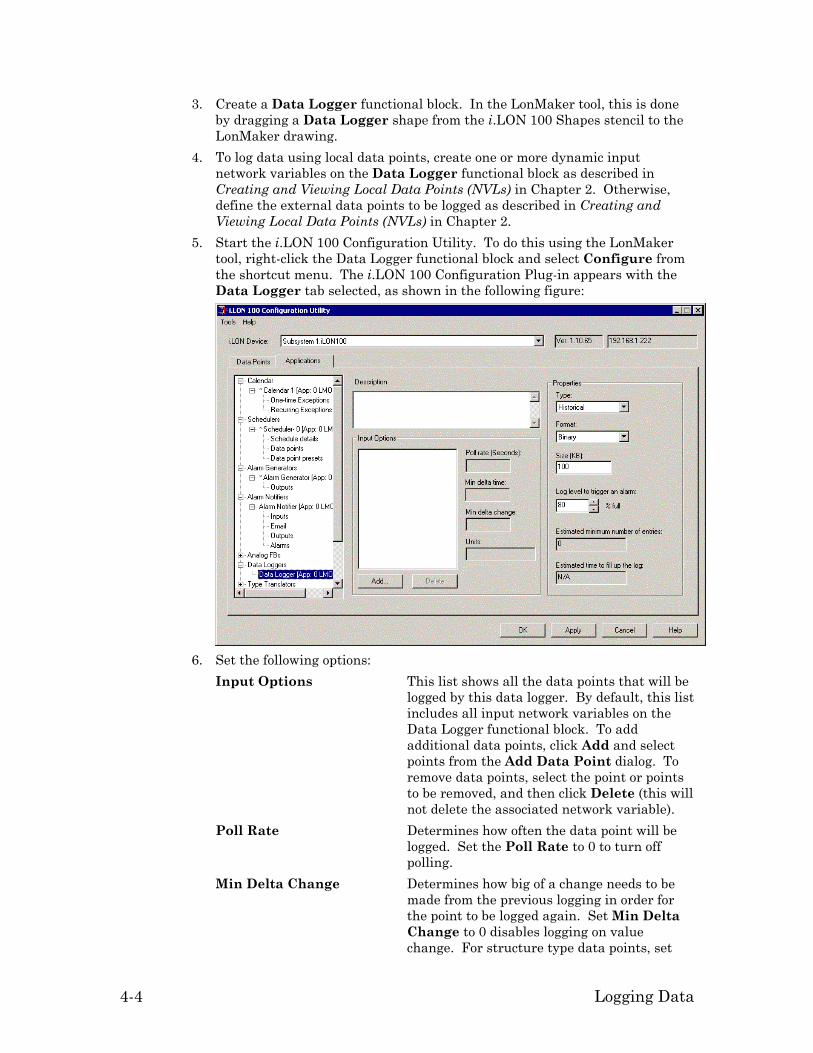
4-4 Logging Data
3. Create a Data Logger functional block. In the LonMaker tool, this is done by dragging a Data Logger shape from the i.LON 100 Shapes stencil to the LonMaker drawing.
4. To log data using local data points, create one or more dynamic input network variables on the Data Logger functional block as described in Creating and Viewing Local Data Points (NVLs) in Chapter 2. Otherwise, define the external data points to be logged as described in Creating and Viewing Local Data Points (NVLs) in Chapter 2.
5. Start the i.LON 100 Configuration Utility. To do this using the LonMaker tool, right-click the Data Logger functional block and select Configure from the shortcut menu. The i.LON 100 Configuration Plug-in appears with the Data Logger tab selected, as shown in the following figure:
6. Set the following options:
Input Options This list shows all the data points that will be logged by this data logger. By default, this list includes all input network variables on the Data Logger functional block. To add additional data points, click Add and select points from the Add Data Point dialog. To remove data points, select the point or points to be removed, and then click Delete (this will not delete the associated network variable).
Poll Rate Determines how often the data point will be logged. Set the Poll Rate to 0 to turn off polling.
Min Delta Change Determines how big of a change needs to be made from the previous logging in order for the point to be logged again. Set Min Delta Change to 0 disables logging on value change. For structure type data points, set

i.LON 100 Internet Server User’s Guide 4-5
the Min Delta Change to any non-zero value to cause any change in value to be logged.
Min Delta Time Determines the minimum amount of time that must pass for a point to be logged again. The data point will not be logged again within this time even if the Min Delta Change threshold is passed.
This dialog also allows you to set the following properties for the Data Logger functional block as a whole: Type The type of the data log maintained by this
Data Logger functional block. Data logs can be one of two types:
Historical – When the data log fills up, data ceases to be logged.
Circular – When the data log fills up, new data overwrites the oldest existing data.
Format The format of the data logs. Available formats are Binary and Comma Separated Value. Data logs can be found on the i.LON 100 in the root\data directory. The name of the log file is log<n>.dat (for binary log files) or log<n>.csv (for comma separated value log files), where <n> is the index number of the Data Logger functional block. Changing the log file format deletes any existing log file.
Size The size of the data log. Each log can be up to 1024 KB, and the i.LON 100 can log up to 10 MB of data. You can view the amount of free disk space using the System Info Web page.
Log Level to Trigger an Alarm
When the data log reaches the specified percent capacity, the nvoDlLevAlarm output network variable will be set to the AL_ALM_CONDITION status.
Estimated Minimum Number of Entries
The minimum number of entries it will take to fill the data log based on the log size and the size of the data points to be logged.
Estimated Time to Fill Up the Log
The estimated amount of time it will take to fill the log based on the log size, the size of the data points to be logged, and the poll rate.
Click Help for a description of other options on this page.
7. The Input Options list shows all the data points that will be logged by this data logger. By default, this list includes all input network variables on the Data Logger functional block. To add additional data points, click Add and select points from the Add Data Point dialog. To remove data points, select the point or points to be removed, and then click Delete (this will not delete the associated network variable).

4-6 Logging Data
Extracting Data Logs You can extract the data logs from the i.LON 100 server via FTP, SOAP requests, or by having them emailed by the alarm notifier. See the i.LON 100 Internet Server Programmer’s Reference for information on using SOAP requests. To extract a data log using FTP, follow these steps: 1. Open an FTP client such as Internet Explorer 6. 2. Point the FTP client to the IP address of the i.LON 100 server (note, FTP
access must be enabled on the Security Web page as described in the i.LON 100 User’s Guide: Installing, Connecting, and Configuring the i.LON 100). You will see the i.LON 100 server directory structure.
3. Open the data folder. You will see a log file for each data logger that you have created. The log files are named log<n>.dat (binary file) or log<n>.csv (comma separated value file) <n> is the index of the functional block to which the log applies. The file type (binary or CSV) is determined by the Format property on the Data Logging tab of the i.LON 100 Configuration Plug-in.
4. Copy this log file to your computer using any method available to your FTP client.
Emailing and Clearing Data Logs You can use an alarm notifier to automatically email a data log when it reaches a specified capacity and clear the data log. Typically, you will send the data log as a comma separated value (.csv file extension), which can be read by spreadsheet and database applications. To do this, follow these steps: 1. Create a Data Logger functional block and an Alarm Notifier functional
block. 2. Connect the nvoDlLevAlarm output network variable of the Data Logger
functional block to the nviAnAlarm input network variable of the Alarm Notifier functional block.
3. Connect the nvoAnAlarmFlag output network variable of the Alarm Notifier functional block to the nviDlClear network variable of the Data Logger functional block. If you are using the LonMaker tool, your LonMaker drawing should now appear as shown in the following figure:
4. Right-click the Data Logger functional block and select Configure from the
shortcut menu. The Data Logger configuration dialog opens. 5. Set Log Level to Trigger an Alarm to the percentage at which you want
the data log to be emailed and cleared.
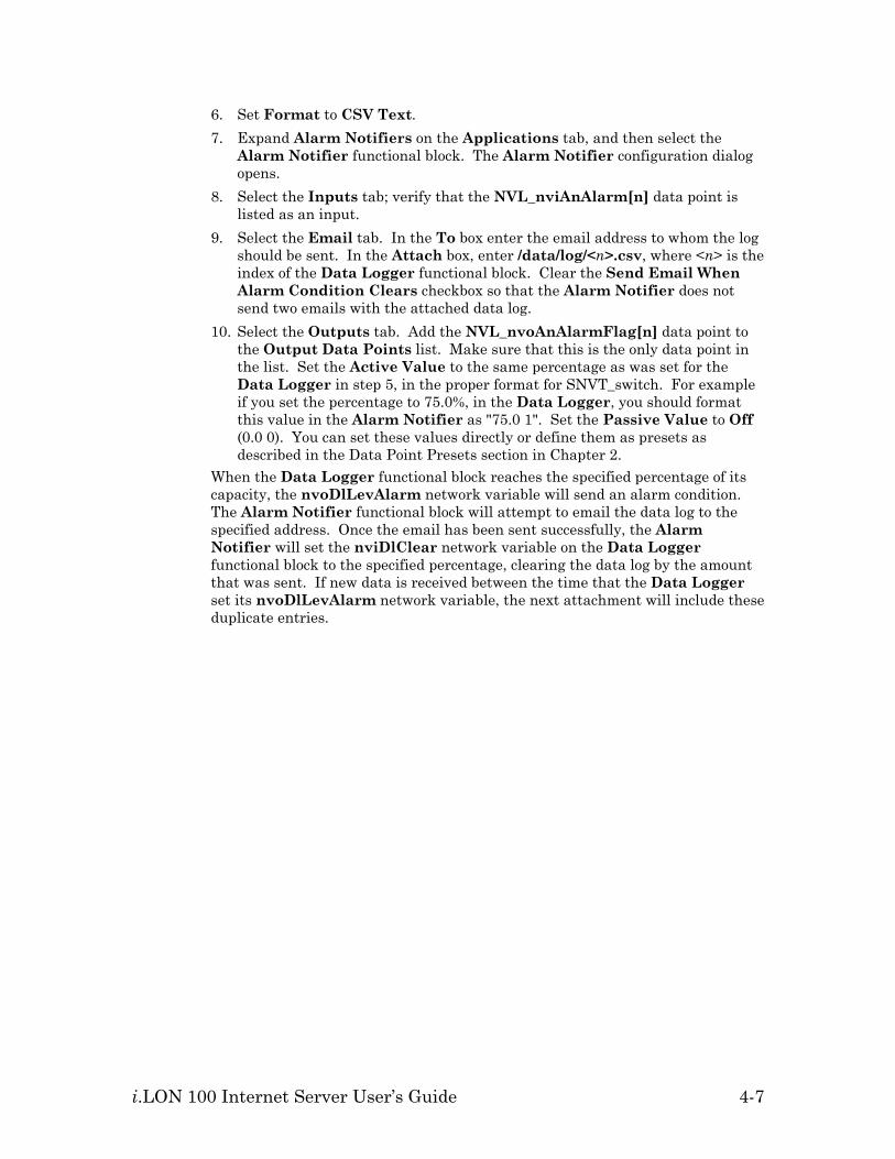
i.LON 100 Internet Server User’s Guide 4-7
6. Set Format to CSV Text. 7. Expand Alarm Notifiers on the Applications tab, and then select the
Alarm Notifier functional block. The Alarm Notifier configuration dialog opens.
8. Select the Inputs tab; verify that the NVL_nviAnAlarm[n] data point is listed as an input.
9. Select the Email tab. In the To box enter the email address to whom the log should be sent. In the Attach box, enter /data/log/<n>.csv, where <n> is the index of the Data Logger functional block. Clear the Send Email When Alarm Condition Clears checkbox so that the Alarm Notifier does not send two emails with the attached data log.
10. Select the Outputs tab. Add the NVL_nvoAnAlarmFlag[n] data point to the Output Data Points list. Make sure that this is the only data point in the list. Set the Active Value to the same percentage as was set for the Data Logger in step 5, in the proper format for SNVT_switch. For example if you set the percentage to 75.0%, in the Data Logger, you should format this value in the Alarm Notifier as "75.0 1". Set the Passive Value to Off (0.0 0). You can set these values directly or define them as presets as described in the Data Point Presets section in Chapter 2.
When the Data Logger functional block reaches the specified percentage of its capacity, the nvoDlLevAlarm network variable will send an alarm condition. The Alarm Notifier functional block will attempt to email the data log to the specified address. Once the email has been sent successfully, the Alarm Notifier will set the nviDlClear network variable on the Data Logger functional block to the specified percentage, clearing the data log by the amount that was sent. If new data is received between the time that the Data Logger set its nvoDlLevAlarm network variable, the next attachment will include these duplicate entries.


i.LON 100 Internet Server User’s Guide 5-1
5
Scheduling
This chapter describes how to use the i.LON 100 Internet Server to create, view, and manage schedules.

5-2 Scheduling
Scheduling Overview The i.LON 100 contains three types of functional blocks used for scheduling applications—the Scheduler, Calendar, and Real Time Clock functional blocks. The Scheduler functional block allows you to define daily schedules that each specify the schedule events for a 24 hour day. Each daily schedule is either a daily schedule or an exception schedule. Daily schedules occur every week on a specified day; each scheduler can contain up to seven daily schedules (i.e. one for each day of the week); you can assign a single daily schedule to multiple days of the week (i.e. you could define one daily schedule for all weekdays and one for weekends). You can create a weekly schedule by assigning a daily schedule to each day of the week. Exception schedules occur on a set of dates defined by an exception; each scheduler can contain up to two exception schedules. Exceptions are ranges of dates defined on the Calendar functional block; these can be ranges like “January 12th to February 2nd” or “Every other Monday” or “the third Monday of every month.” The exceptions defined on the calendar can be used by any number of schedulers. The Real Time Clock functional block maintains the current date and time that is used by the Scheduler and Calendar functional blocks, and can also provide date and time data to other devices. The i.LON 100 includes one Real Time Clock and one Calendar functional block and 40 Scheduler functional blocks. These functional blocks are described in the following sections.
The Scheduler Functional Block The i.LON 100 includes 40 Scheduler functional blocks. You can use a scheduler to generate time-based updates to the data points in your network. You will select a data point or group of data points for each scheduler you create. You will define daily and exception daily schedules on each scheduler. You can create up to seven daily and two exception schedules on a single scheduler. Each schedule is identified by a unique name. For example, you may define two daily schedules, one named “Weekday” (to occur every weekday) and one named “Weekend” (to occur every weekend day) and two exception schedules, “Holiday” (to occur on specified holiday dates) and “Inventory” (to occur on a specified regular interval). The dates for the “Holiday” and “Inventory” schedules are derived from exceptions defined in the Calendar functional block. A schedule event specifies a time and a value. At the specified time, the value is sent to all of the scheduler’s output data points (defined on the Outputs tab); if the scheduler drives output data points of different types, you will need to define presets for each of the data points (see Data Point Presets in Chapter 2). For example, you can create a scheduler that sets two data points – one SNVT_switch data point and one SNVT_temp_f – to a MorningWarmup preset at 6:00 on weekdays, a DayTime preset at 8:00 on weekdays, and a NightWeekend preset at 18:00 on weekdays; on weekends, the data points are left set to the NightWeekend preset on weekends. Using the Presets tab, you would define the presets for these data points as shown in the following table:

i.LON 100 Internet Server User’s Guide 5-3
MorningWarmup DayTime NightWeekend
SNVT_switch 100.0 1 100.0 1 0.0 0
SNVT_temp_f 25 22 18
You can create exception schedules that become active based on exceptions that you define using the Calendar functional block. You can use exceptions to select exception schedules that become active on specific dates that require a unique schedule, such as holidays or special events, and assign them a unique schedule within your scheduler. You can set up a separate daily schedule for each exception. This allows you to specify what value you want your data points to use on each exception date at any given time. When using exceptions, multiple schedule events may become active at the same time. You will assign a schedule priority to each schedule event. This value can be from 0 (highest priority) to 255 (lowest priority). If two schedules conflict—for example a daily schedule and an exception schedule —the one with the higher priority takes precedence. You can create one or more outputs from a scheduler by adding dynamic network variable outputs to the Scheduler functional block. You can connect these outputs to any input network variables that require activation on a scheduled interval. Each Scheduler functional block contains a single nviEsEnable network variable input as shown in the following figure:
The nviEsEnable input is a SNVT_switch network variable that disables the Scheduler functional block. To disable a Scheduler functional block (i.e. to not update the points as specified in the i.LON 100 Configuration Plug-in), set this network variable to Off (0.0 0). In the absence of any input, this network variable defaults to On (100.0 1), so the Scheduler functional block will be enabled unless explicitly disabled. To generate outputs from a scheduler, use an LNS installation tool such as the LonMaker tool to add one or more output dynamic network variable outputs to it as described in Creating and Viewing Local Data Points (NVLs) in Chapter 2. Define preset values for these outputs as defined in Data Point Presets in Chapter 2. Configure the schedules for these outputs as described in this chapter.
The Calendar Functional Block The i.LON 100 includes 1 Calendar functional block. You can use this functional block to create up to 256 exception exceptions to be used by your Scheduler functional blocks. Each exception that you create represents a date, or a group of dates. When you reference an exception in a scheduler, you will be able to assign an exception schedule to each exception. You can use exceptions to assign alternate daily schedules to use on particular dates such as holidays or special events.

5-4 Scheduling
The Calendar functional block contains a single nviEcDateResync network variable input and a single nvoEcDateEvent output as shown in the following figure:
nvoEcDateEvent This output network variable reports the status of
each exception that you define as described in Creating Exception. This output is internally connected to the i.LON 100 Node Object functional block and all the i.LON 100 Scheduler functional blocks. Every day at 12:00pm (noon) it resynchronized by sending all Scheduler functional blocks updates informing them of the exception status and time to the next date event. When the clock is set manually before 12:00pm on a particular day, the Calendar will resynchronize immediately. After this irregular resyncronization, the daily resyncronization will be cancelled for that day, and it will resume at noon on the following day.
Use this network variable to synchronize schedules on multiple i.LON 100 devices, as described in Using the Same Exception Schedule on Multiple i.LON 100 Devices, later in this chapter.
nviEcDateResync This SNVT_switch input network variable requests an update on the status of all defined exceptions. When the state of this input changes from Off to On, the Calendar functional block sends a series of updates on the nvoEcDateEvent output, one for each defined exception. The input is On when the state value is one (1) and the level value is greater than zero (0). This input is internally connected to the i.LON 100 Node Object functional block and all the i.LON 100 Scheduler functional blocks.
Use this network variable to synchronize schedules on multiple i.LON 100 devices, as described in Using the Same Exception Schedule on Multiple i.LON 100 Devices, later in this chapter.
Using the Same Exception Schedule on Multiple i.LON 100 Devices If you have multiple i.LON 100 devices in the same LonWorks network that use the same exception schedule (holidays, maintenance days, etc.), you can bind the

i.LON 100 Internet Server User’s Guide 5-5
Calendar functional block of the source i.LON 100 to the Node Object functional block of the destination i.LON 100. To do this, follow these steps: 1. Connect the nvoEcDateEvent output network variable on the source i.LON
100 device’s Calendar functional block to the nviDateEvent input network variable on the destination i.LON 100 device’s Node Object functional block.
2. Connect the nvoDateResync output network variable on the destination i.LON 100 device’s Node Object functional block to the nviEcDateResync input network variable on the source i.LON 100 device’s Calendar functional block.
In addition, the configuration of the Calendar functional block is stored in the /root/config/software/EventCalendar.xml file. If you want to copy schedule information to an i.LON 100 that is not in the same LONWORKS network, you can configure the Calendar on one i.LON 100 device (i.e. define all exceptions) and FTP this file to the same location on all other i.LON 100 devices that should share the same schedule.
The Real Time Clock Functional Block Shape The i.LON 100 includes 1 Real Time Clock functional block. It maintains the current date and time. It includes the following input and output network variables:
nviRtTimeZone This SNVT_time_zone input network variable
sets the time zone. You can also set the time zone on the TCP/IP Web page as described in the i.LON 100 User’s Guide: Using the i.LON 100 Web Pages to Configure Applications and to Monitor and Control Data Points.
nvoRtTimeDate This SNVT_time_stamp output network variable reports the current date and time. You can set the current date and time (configure the i.LON 100 to obtain this information from an SNTP server) on the TCP/IP Web page as described in the i.LON 100 User’s Guide: Using the i.LON 100 Web Pages to Configure Applications and to Monitor and Control Data Points.
nvoRtSummerTime This SNVT_time_stamp output network variable reports the date of the beginning of daylight savings time.
nvoRtWinterTime This SNVT_time_stamp output network variable reports the date of the end of daylight savings time.

5-6 Scheduling
Creating a Schedule A typical schedule consists of a weekly schedule that defines the daily schedule to be used for each day of the week, and up to two exception schedules that allow alternate daily schedules to become active on specified dates. Before creating a schedule, you should already have created a LonWorks network that controls the functions you wish to schedule. To create a schedule, follow these steps: 1. Plan Out Your Schedule – Write out your desired schedule. For example, “On
weekday mornings at 06:00 the heating system should be started and the thermostat set to 65 degrees F (18 degrees C). At 08:00, the thermostat should be set to 70 degrees F (21 degrees C).” etc. See Planning Out Your Schedule for more information.
2. Add a Scheduler Functional Block to the LonWorks Network – Use an LNS installation tool such as the LonMaker tool to add a Scheduler functional block to the network drawing. See Adding a Scheduler Functional Block to a LonWorks Network for more information.
3. Define Outputs – Using the schedule written in step one, decide what data points in your network need to be written by the scheduler. Optionally add dynamic output network variables to the Scheduler functional block and then add the appropriate data points to the Scheduler functional block’s Data Points window. Connect these output network variables to the corresponding input network variables. See Defining Outputs for more information.
4. Define Presets – Use the Data Point Presets window of the Scheduler functional block to define presets for each of the data points defined on the Data Points window. See Defining Presets for more information.
5. Create Daily Schedules – Use the Scheduler functional block to define a schedule for each day of the week. Each daily schedule consists of zero or more events. An event consists of a time and a preset value (i.e. 06:00:Warmup). When an event occurs, the data points specified on the Data Points window will be set to the values associated with the preset on the Data Points Presets window. Each day of the week can have a different schedule. See Creating Daily Schedules for more information.
6. Create Exceptions – Use the Calendar functional block to define exceptions: date ranges during which the weekly schedule will be overridden. These exceptions can be specific ranges of dates (i.e. “March 27th-April 6th, 2002”) or dates in a certain pattern (i.e. “The second Tuesday of every month” or “Every other Saturday”). For each of these exception schedules, use the Scheduler functional block to define the schedule that will be used on that day. See Creating Exception Schedules for more information.
7. Optionally Create One-time Overrides – You can optionally use the Scheduler functional block to create a daily schedule that will override the schedule for a specified range of dates. See Creating a One-time Override Schedule for more information.
Planning Out Your Schedule Before implementing a schedule using the Scheduler and Calendar functional blocks, you should write out the schedule so you have a full understanding of all the schedules and events you will need to create.
i.LON 100 Internet Server User’s Guide 5-7
Example of Planning Out a Schedule The following is an example of a simple schedule that might be created to schedule HVAC and lighting controls in a retail store:
On weekdays, the heat should be set to 60 degrees F (16 degrees C) at 07:00 (Warmup), 70 degrees at 09:00 (Open), and turned off at 19:00 (Closed). On weekdays, the lighting should be turned on at 09:00 (Open) and turned off at 19:00 (Closed). On weekends, the heating and lighting should remain off. On the first Sunday of each month, for inventory, the heat should be set to 65 degrees F (18 degrees C) at 09:00 (OpenInventory) and turned off at 18:00 (Closed). On the first Sunday of each month, for inventory, the lighting should be turned on at 09:00 (OpenInventory) and turned off at 18:00 (Closed). Every year you will have a winter vacation. In 2003-2004, you would like it to last from December 23rd to January 3rd, but you would like to be able to change the dates of the vacation every year.
Adding a Scheduler Functional Block to a LonWorks Network
To add a Scheduler functional block to a LONWORKS network, follow these steps: 1. Open the network that controls the functions you want to schedule in an LNS
installation tool such as the LonMaker tool. 2. Use an existing i.LON 100 device in the network, or create and commission a
new i.LON 100 device. 3. Add a Scheduler functional block. For example, using the LonMaker tool,
drag a Scheduler functional block shape from the i.LON 100 Shapes stencil to the LonMaker drawing. The LonMaker New Functional Block wizard appears.
4. Associate the Scheduler functional block shape with one of the Scheduler functional blocks on the i.LON 100 device. See the installation tool documentation for more information.
Defining Outputs To define outputs, follow these steps: 1. Determine which data points should be modified by the scheduler. 2. If these data point represent input network variables on a LonWorks
network, you can optionally create complimentary dynamic output network variables on the Scheduler functional block. You may want to create a single output network variable to connect to multiple input network variables (for example, if you want to send a temperature setpoint to multiple heating controllers on the network). See the installation tool documentation for more information on creating dynamic network variables.
3. Start the i.LON 100 Configuration Plug-in as described in Starting the i.LON 100 Plug-in in Chapter 1.
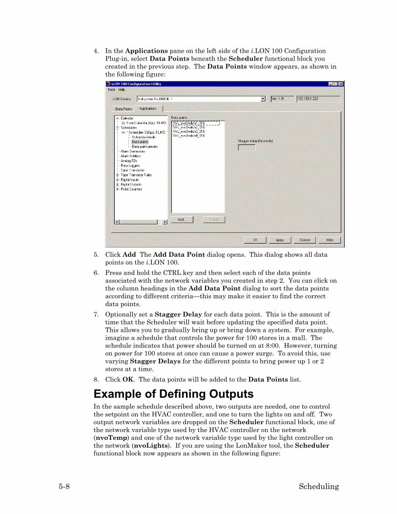
5-8 Scheduling
4. In the Applications pane on the left side of the i.LON 100 Configuration Plug-in, select Data Points beneath the Scheduler functional block you created in the previous step. The Data Points window appears, as shown in the following figure:
5. Click Add The Add Data Point dialog opens. This dialog shows all data
points on the i.LON 100. 6. Press and hold the CTRL key and then select each of the data points
associated with the network variables you created in step 2. You can click on the column headings in the Add Data Point dialog to sort the data points according to different criteria—this may make it easier to find the correct data points.
7. Optionally set a Stagger Delay for each data point. This is the amount of time that the Scheduler will wait before updating the specified data point. This allows you to gradually bring up or bring down a system. For example, imagine a schedule that controls the power for 100 stores in a mall. The schedule indicates that power should be turned on at 8:00. However, turning on power for 100 stores at once can cause a power surge. To avoid this, use varying Stagger Delays for the different points to bring power up 1 or 2 stores at a time.
8. Click OK. The data points will be added to the Data Points list.
Example of Defining Outputs In the sample schedule described above, two outputs are needed, one to control the setpoint on the HVAC controller, and one to turn the lights on and off. Two output network variables are dropped on the Scheduler functional block, one of the network variable type used by the HVAC controller on the network (nvoTemp) and one of the network variable type used by the light controller on the network (nvoLights). If you are using the LonMaker tool, the Scheduler functional block now appears as shown in the following figure:

i.LON 100 Internet Server User’s Guide 5-9
When you add the two data points associated with the output network variables to the Data Points pane, the list appears as shown in the following figure:
Defining Presets To define presets for the outputs configured on the Data Points page, follow these steps: 1. Define each event that will be triggered by any schedules. In the Example of
Planning Out a Schedule procedure a name was given to each of the events. Use your written out schedule to determine what events will occur and what state the outputs should be set to for each event.
2. Under the appropriate Scheduler in the applications tab, select Data Point Presets. The Data Point Presets window opens, as shown in the following figure:

5-10 Scheduling
All data points added to the Data Points list in the previous step will be listed. Some presets may already have been defined on the Data Points tab of the i.LON 100 Configuration Plug-in (see Creating Data Point Presets in Chapter 2).
3. Click Add Preset. The Add Preset dialog appears, as shown in the following figure:
4. Enter the name of the preset in Preset Name. Leave Copy Values from
Preset set to <None>. 5. Repeat steps 3 and 4 for each preset you defined in step 1. When you are
done, each preset name will be listed across the top of the Presets spreadsheet.
6. For each preset, set the value to which each data point should be set.
Example of Defining Presets In the example described above, four presets are needed, Warmup, Open, Closed, and OpenInventory. Once added and configured, the presets table should appear as shown in the following figure:
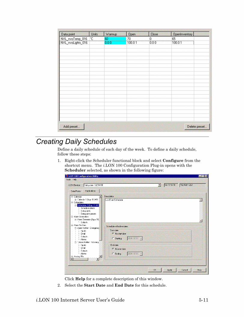
i.LON 100 Internet Server User’s Guide 5-11
Creating Daily Schedules Define a daily schedule of each day of the week. To define a daily schedule, follow these steps: 1. Right-click the Scheduler functional block and select Configure from the
shortcut menu. The i.LON 100 Configuration Plug-in opens with the Scheduler selected, as shown in the following figure:
Click Help for a complete description of this window.
2. Select the Start Date and End Date for this schedule.

5-12 Scheduling
3. Click Schedule Details under the selected Scheduler in the Applications list. The Schedule Details dialog opens, as shown in the following figure:
4. Click Add under the Schedules list to open the Add New Schedule dialog,
shown in the following figure:
5. Enter the following information to add a new daily schedule:
Name The name of the new daily schedule. This can be up to 228 characters.
Priority The priority of the new daily schedule. This value can be from 0 (highest priority) to 255 (lowest priority). If two daily schedules conflict — for example a daily schedule and an exception — the one with the higher priority value takes precedence.

i.LON 100 Internet Server User’s Guide 5-13
Type of Schedule When creating a daily schedule, select Daily Schedule.
6. Click OK to create the new daily schedule. The new daily schedule appears in the Schedules list.
7. Select the days of the week to which this schedule will apply using Days. Set the check box for all days that this daily schedule should be active.
8. Add one or more events to the schedule. To add an event, click Add under the Events list or double-click the first column of the first empty row in the Events list. The Add New Event dialog opens, as shown in the following figure:
9. Set the time for the new event and then click OK. A new event appears in
the Events list. The Time will be the time you selected, and the Value will be empty.
10. Select a preset value for the new event. This should be one of the presets created in the previous step.
11. Create additional daily schedules. For example, you can create one schedule for Monday through Thursday, one schedule for Friday, and one schedule for the weekend. You can create up to 7 daily schedules in a single Scheduler functional block.
12. Click OK or Apply to save the changes to the i.LON 100 device.
Example of Creating a Daily Schedule The following figure shows the weekday schedule created to match the example described above:

5-14 Scheduling
Creating Exception Schedules Once you have created daily schedules for each day of the week, you can add exceptions to the schedule. You can create an exception using the Calendar functional block, and then add it as an exception schedule to one or more Scheduler functional blocks. You do not have to add a Calendar functional block shape to the LonMaker drawing in order to be access the Calendar funcatinal block from the i.LON 100 Configuration Plug-in. You can create two kinds of exceptions: one-time exceptions, and recurring exceptions. One-time exceptions specify a single range of dates. For example, if a building were being shut down for two weeks for maintenance, you could create a one-time exception for those dates. Recurring exceptions occur at regular intervals. For example, you can create a recurring exception for a yearly holiday or for an inventory procedure that takes place on the second Monday of every month. To create an exception, follow these steps: 1. Open an existing LonMaker network or create a new LonMaker network as
described in the LonMaker User’s Guide. 2. Use an existing i.LON 100 device in the LonMaker network, or create and
commission a new i.LON 100 device. 3. Right-click the i.LON 100 device shape and select Configure from the
shortcut menu. The i.LON 100 Configuration Plug-in opens. 4. Select the Applications tab and then select One-time Exceptions or
Recurring Exceptions from beneath the Calendar application on the applications pane on the left side of the i.LON 100 Configuration Plug in.
5. On either tab, click Add to open the New Exception dialog, as shown in the following figure:

i.LON 100 Internet Server User’s Guide 5-15
6. Enter the name of the new exception and then click OK. The new exception
will be added to the Exceptions list. 7. Select the new exception from the Exceptions list. The fields in Exception
Details will highlight. 8. If you are in the One-time Exceptions tab, Exception Details appears as
shown in the following figure:
9. Use the Start Date and End Date columns to select the start and end dates
for the exception. Each exception can have up to 16 date ranges. Select the Temporary Exception check box to have the exception removed once the last date specified in the End Date column has passed. If this check box is cleared, the exception will remain and the dates can be updated (i.e. if you have an exception schedule that will be used at irregular intervals). If you are in the Recurring Exceptions window, Exception Details appears as shown in the following figure:

5-16 Scheduling
These fields allow you to set how often the exception occurs. Click Help for more information.
10. Once you have defined one or more exceptions, click the Scheduler tab and the Schedule Details tab. The exceptions you created are listed in Exceptions.
11. Click Add below the Schedules list to open the New Schedule dialog, shown in the following figure:
12. Enter the following information to define a new daily schedule:
Name The name of the new schedule. This field can be up to 228 characters.
Priority The priority of the new schedule. This number can be from 0 (highest priority) to 255 (lowest priority). If two schedules conflict—for example a daily schedule and an exception

i.LON 100 Internet Server User’s Guide 5-17
schedule—the one with the higher priority value takes precedence. When creating an exception schedule, set the Priority higher than the priority used for the daily schedule.
Type of Schedule When creating an exception schedule, select Exception Schedule.
13. Click OK to create the new exception schedule. The new schedule will appear in the Schedules list.
14. Select the new schedule from the Schedules list. Since you have created an exception schedule, the Days field is grayed out, while the Exceptions field is highlighted.
15. Select the exceptions to which the new schedule will apply. Each schedule can apply to multiple exceptions. For example, if you created recurring exceptions for Christmas, the Fourth of July, Presidents Day, and New Years, you can create a holiday schedule that would apply to those dates.
16. Optionally add one or more events to the schedule (you can leave a schedule empty to indicate that the scheduler should remain dormant on that day). To add an event, click Add under the Events list or double-click the first column of the first empty row in the Events list. The Add New Event dialog opens, as shown in the following figure:
17. Use this dialog to set the time for the new event and click OK. An event will
appear in the Events list. The Time will be the time you selected, and the Value will be Default. This indicates that at the specified time, all the data points specified in the Data Points tab will be set to their Default value, as specified in the Presets tab (see Data Point Presets in Chapter 2 for more information on data point presets).
18. To change the value to which the data points will be set, click the value to open a shortcut menu that allows you to set any of the preset values available in the Presets tab for the collection of data points in the Inputs tab. You can set the value for multiple data point of the different types as long as the preset value you specify is defined for each data point (see Data Point Presets in Chapter 2 for more information on data point presets). You can also enter a value manually, but you must ensure that it is a valid value for all data points in the Inputs tab (the Configuration Plug-in will not validate it).
19. Create additional exception schedules as described above. You can create up to three exception schedules in a single Scheduler functional block.
Example of Creating Exception Schedules In the example described above, two exception schedules are created, one recurring exception (Inventory, on the first Sunday of each month) and one one-time exception (Vacation, dates to be set manually every year).

5-18 Scheduling
The Recurring Exceptions window for the Inventory schedule appears as shown:
The One-time Exceptions window for the Vacation schedule appears as shown:

i.LON 100 Internet Server User’s Guide 5-19
Deleting Exception Schedules You can delete one-time or recurring exceptions in the Calendar functional block by selecting the exception from the Exceptions list and clicking Delete. If you delete an exception, you should assure that you remove the reference to the exception from all Scheduler functional blocks on the i.LON 100; if a Scheduler references a non-existent exception, the Scheduler may be rendered unoperational.
Creating a One-time Override Schedule You can create a one-time override schedule to implement a temporary exception schedule for a single range of dates. A one-time override schedule is never recurring. One-time override schedules count against the total of two exception schedules (i.e. exception schedules) that can exist on a scheduler, so you cannot create one if the scheduler already has two exception schedules defined. To create a one-time override schedule, follow these steps: 1. Right-click the Scheduler functional block that you want to override and
select Configure from the shortcut menu. The i.LON Configuration Utility opens with the Scheduler tab selected.
2. Select the Schedule Details tab. 3. Verify that the correct Scheduler functional block is selected in the
Schedulers folder in the Functional Blocks list and then click Add. The New Schedule dialog opens as shown in the following figure:
4. Enter the following information to define a new daily schedule:
Name The name of the new schedule. Creating a one-time override schedule creates a temporary exception of the same name in the Calendar functional block, so the override schedule name must not match an existing exception name.
Priority The priority of the new schedule. This number can be from 0 (highest priority) to 255 (lowest priority). If two schedules conflict—for

5-20 Scheduling
example a daily schedule and a one-time override schedule—the one with the higher priority takes precedence. When creating a one-time override schedule, set the Priority higher than the priority used for the current day’s daily schedule.
Type of Schedule When creating a one-time override schedule, select One-time Override Schedule.
5. Click OK to create the one-time override schedule. The new schedule appears in the Schedules list with an asterisk next to it to indicate it is a one-time override schedule.
6. Select the new schedule from the Schedules list. Enter the start and end dates for the override schedule under One-time Exception Details.
7. Optionally add one or more events to the schedule (you can leave a one-time override schedule empty to indicate that the Scheduler should remain dormant on that day). To add an event, click Add under the Events list or double-click on the first column of the first empty row in the Events list. The Add New Event dialog opens, as shown in the following figure:
8. Set the time for the new event and click OK. An event will appear in the
Events list. The Time will be the time you selected, and the Value will be Default. This indicates that at the specified time, all the data points specified in the Data Points tab will be set to their Default value, as specified in the Presets tab (see Data Point Presets in Chapter 2 for more information on data point presets).
9. To change the value to which the data points will be set, click the value to open a shortcut menu that allows you to set any of the preset values available in the Presets tab for the collection of data points in the Inputs tab. You can set the value for multiple data point of the different types as long as the preset value you specify is defined for each data point (see Data Point Presets in Chapter 2 for more information on data point presets). You can also enter a value manually, but you must ensure that it is a valid value for all data points in the Inputs tab (the Configuration Plug-in will not validate it).
10. Once you have finished entering events for the one-time override schedule, click OK. Once the dates of the one-time override schedule have passed, it will be removed automatically.
Recovering from a Power Outage If the i.LON 100 device loses power and power is later restored, it will attempt to set the appropriate outputs given the current date and time. To do this, it will look at the schedule in use for that day and the most recent event for that schedule.

i.LON 100 Internet Server User’s Guide 5-21
For example, the i.LON 100 was executing a weekday schedule with the following events: 06:00 Warmup 08:00 Daytime 18:00 Cooldown 19:00 Nighttime At 04:30 there was a power outage, and power was restored at 09:00. Since the most recent event was the 08:00 Daytime event, the i.LON 100 would set its output data points to the values specified by the Daytime preset. Any events that should have happened in the ensuing time (in this case, the Warmup event) will not be processed.


i.LON 100 Internet Server User’s Guide 6-1
6
Using Digital Inputs and Digital Outputs
This chapter describes how to use the i.LON 100 Internet Server’s two digital inputs and two digital outputs.

6-2 Using Digital Inputs and Digital Outputs
Digital Input Overview The i.LON 100 device includes two digital inputs. These can be used to connect the i.LON 100 device to a digital device that does not include a LONWORKS interface such as a switch or pushbutton. The i.LON 100 device contains two Digital Input functional blocks. The Digital Input functional blocks include the following input and output network variables:
nvoClsValue This SNVT_switch output network variable
sends the state of the digital input (i.e. 100.0 1 for On, 0.0 0 for Off). This value is derived from the raw digital input value according to the settings of the i.LON 100 Configuration Software, as described below.
nvoClsSetting This SNVT_setting output network variable sends the state of the digital input (i.e. ST_ON 0 0.0 for On and ST_OFF 0 0.0 for Off; only the function field is used). It is provided for compatibility with systems that use SNVT_setting, such as occupancy controllers and constant light controllers.
nviClsValueFb This SNVT_switch input network variable is used to synchronize a group of switches. See the LONMARK Closed-Loop Sensor Functional Profile for more information. This network variable only works when bound.
Using a Digital Input To use digital input, follow these steps: 1. Choose one of the two digital inputs. Connect one side of the input to ground
and one side to a 12V current source (such as the one provided by +12V < 20mA output – see the i.LON 100 User’s Guide: Installing, Connecting, and Configuring the i.LON 100) that runs through a switch or dry-contact relay. When no current is received (i.e. the relay is open), there is no voltage difference, so the digital input will register On; when current is received, there will be a 12V difference and the digital input will register Off.
2. Open an existing LonMaker network or create a new LonMaker network as described in the LonMaker User’s Guide.
3. Use an existing i.LON 100 device in the LonMaker network, or create and commission a new i.LON 100 device as.
4. Drag a Digital Input functional block shape from the i.LON 100 stencil to the LonMaker drawing. The LonMaker New Functional Block wizard appears.

i.LON 100 Internet Server User’s Guide 6-3
5. Select Digital Input 1 or Digital Input 2 in Functional Block – Name. These correspond to hardware digital inputs 1 and 2. Select the appropriate functional block. Click OK. The Digital Input functional block shape appears.
6. Right-click the new Digital Input functional block and then select Configure from the shortcut menu. The i.LON 100 Configuration Plug-in opens and prompts you for the IP address of the i.LON 100 server.
7. Enter the IP address of the i.LON 100 server and then click OK. The Digital Input tab opens, as shown in the following figure:
8. Enter the following information:
Location A description of the location of the physical input associated with this Digital Input functional block. The location can be up to 30 characters. This information will not affect the operation of the functional block.
Input Type Select Switch or Push Button. If you select Switch, the nvoClsValue network variable reflects the state of the hardware input (i.e. when the digital input is On, the nvoClsValue network variable sends 100.0 1). If you select Push Button, the nvoClsValue network variable will change state every time the hardware input transitions from a low to high value.
Invert Input Set this check box to invert the input from the Value network variable. This is typically only used in conjunction with the Switch Input Type.
9. Click OK or Apply to save the settings.

6-4 Using Digital Inputs and Digital Outputs
Digital Output Overview The i.LON 100 device includes two dry-contact relay outputs. You can use these outputs to connect the i.LON 100 device to a digital device that does not include a LONWORKS interface such as a drive contactor or alarm bell. The i.LON 100 device contains two Digital Output functional blocks. The Digital Output functional blocks include the following input and output network variables:
nviClaValue This SNVT_switch input network variable
accepts an On (100.0 1) or Off (0.0 0) value. This value drives the digital output’s hardware relay according to the settings of the i.LON 100 Configuration Plug-in, as described below.
nviClaValueFb This SNVT_switch output network variable reflects the last value sent to the nviClsValue network variable. This is used to synchronize a group of outputs. See the LONMARK Closed-Loop Sensor Functional Profile for more information.
Using a Digital Output To use a digital output, follow these steps: 1. Connect the one of the two relay outputs to a digital input. 2. Open an existing LonMaker network or create a new LonMaker network as
described in the LonMaker User’s Guide. 3. Use an existing i.LON 100 device in the LonMaker network, or create and
commission a new i.LON 100 device. 4. Drag a Digital Output functional block shape from the i.LON 100 stencil to
the LonMaker drawing. The LonMaker New Functional Block wizard appears.
5. Select Digital Output 1 or Digital Output 2 in Functional Block – Name. These correspond to relay outputs 1 and 2. Select the appropriate functional block.
6. Click OK. The Digital Output functional block shape appears. 7. Right-click the new Digital Output functional block and select Configure
from the shortcut menu. The i.LON 100 Configuration Plug-in opens and prompts you for the IP address of the i.LON 100 server.
8. Enter the IP address of the i.LON 100 server and then click OK. The Digital Output tab opens, as shown in the following figure:

i.LON 100 Internet Server User’s Guide 6-5
9. Enter the following information:
Location A description of the location of the physical output associated with this Digital Output functional block. The location can be up to 30 characters. This information will not affect the operation of the functional block.
Invert Output Set this check box to invert the output sent to the hardware. If this check box is cleared, the Digital Output functional block will close the relay when nviClaValue is set to On (100.0 1), and will open the relay when the nviClaValue is set to Off (0.0 0). If this check box is set, the Digital Output functional block will open the relay when the nviClaValue network variable is set to On, and close the relay when nviClaValue is set to Off.
10. Click OK or Apply to save the settings.


i.LON 100 Internet Server User’s Guide 7-1
7
Using the Type Translator
This chapter describes how to use the i.LON 100 Internet Server’s Type Translator functional block to translate data from one network variable type to another.

7-2 Using the Type Translator
Type Translator Overview The i.LON 100 includes 40 Type Translator functional blocks. A type translator allows you to translate data from one network variable type to another. You can use scalar-based translation and rule-based translation. Scalar-based translation allows you to translate one floating point or integer network variable to another floating point or integer network variable. Rule-based translation uses one of the Type Translators rules to translate from one network variable type to another. The Type Translator ships with a number of pre-defined rules and you can create custom rules using the i.LON 100 Configuration Plug-in as described in Creating a Custom Type Translator Rule, later in this chapter. Rule-based translation can involve translating a single input into many outputs or vice versa. The Type Translator functional block initially has no network variables, as shown in the following figure:
You will dynamically add input and output network variables of the appropriate types for the translation you want to implement.
Using the Type Translator Functional Block To use a type translator, follow these steps: 1. Open an existing LonMaker network or create a new LonMaker network as
described in the LonMaker User’s Guide. 2. Use an existing i.LON 100 device in the LonMaker network, or create and
commission a new i.LON 100 device. 3. Drag a Type Translator functional block shape from the i.LON 100 stencil to
the LonMaker drawing. 4. Use the LonMaker New Functional Block wizard to associate the Type
Translator functional block shape with any of the available Type Translator functional blocks on the i.LON 100.
5. Optionally add dynamic network variables to the Type Translator functional block as described in Creating and Viewing Local Data Points (NVLs) in Chapter 2. These network variables can be used as local data points.
6. Right-click the Type Translator functional block and select Configure from the short-cut menu. The i.LON 100 Configuration Plug-in opens and prompts you for the IP address of the i.LON 100 hardware.
7. Enter the IP address of the i.LON 100 and then click OK. The i.LON 100 Configuration Plug-in options with the Type Translator tab selected, as shown in the following figure:

i.LON 100 Internet Server User’s Guide 7-3
Click Help for a description of all the fields in this tab.
8. To create a scalar-based translation, select <None> from Rule Name, and then click Add Scalar Type Data Point to add a scalar point to the Input and Output lists. You can add as many input/output pairs as required. In each case, the input is translated to the corresponding output. To create a rule-based translation, select the translation rule you want to use from Rule Name. The Input and Output lists will be filled in according to the rule you select. For example, if you select the 16xSNVT_switch_TO_SNVT_state rule, the Input list will display 16 SNVT_switch type inputs, and the Output list will display one SNVT_state type output. Click Help for a complete list and description of all rules provided with the i.LON 100 Configuration Software. For information on creating a custom rule, see Creating a Custom Type Translator Rule, later in this chapter.
9. Select a data point of the appropriate type for each entry in the Input and Output lists. To do this, double-click the Name column next to the entry to see a shortcut menu of all data points of the appropriate type.
10. Click OK or Apply to save changes.
Creating a Custom Type Translator Rule You can use the i.LON 100 Configuration Software to create custom type translator rules. You can use custom rules to translate data from any number of input network variables to any number of output network variables. To create a custom rule you will define the inputs and outputs of the rule, and create one or more cases that define how the rule will behave with various inputs. To create a custom rule, follow these steps: 1. In the Applications tab of the i.LON 100 Configuration Software, select
Type Translator Rules from the Applications list. 2. Right click Type Translator Rules in the Applications list and select Add
from the shortcut menu. The Add Application dialog appears. Enter the

7-4 Using the Type Translator
name of the new rule in Application Name and click OK. The new rule appears on the Applications list.
3. Select the new application. The following dialog appears:
4. Click the Add button under Input Format Type. The Set Data Point
Format dialog appears, as shown in the following figure:
Select a data type that will be used as an input for this rule. If this rule will accept multiple inputs of this type, set Number of Data Points to Create appropriately.

i.LON 100 Internet Server User’s Guide 7-5
5. Click OK. The data point or data points specified will appear in the Input Format Type list.
6. To add more input data points, click Add and repeat step 4. 7. Add one or more output data points using the Add button under the Output
Format Type list, using the same method described in steps 4-6 for input data points.
8. Once you have defined all the inputs and outputs, expand the new rule the Applications list and then click Cases. The Cases dialog appears, as shown in the following figure:
9. Expand the Cases item under your translation rule in the Applications list. Select one of the cases you created. The Rules dialog opens:

7-6 Using the Type Translator
10. Click the Add Rule button to create a new rule for this case. Click Help for
more information on defining rules. 11. Define rules for all defined cases. The i.LON 100 Configuration Software
does not do any verification of your cases and rules; you must make sure what you have defined makes sense. Once you are finished, click Apply. The new rule will now appear in Rule Name in the Type Translator dialog.
Tutorial: Integrating M-Bus Devices in a LonWorks Network Using the Type Translator Functional Block
This tutorial describes how to expose the data from a generic M-Bus device as a network variable on a LonWorks network. The techniques covered in this tutorial may be applied to any M-Bus device that you want to integrate with your i.LON 100. Before starting this tutorial, you should already have installed an M-Bus device using the M-Bus driver Web page (see above). You should also create a LonMaker drawing that includes the i.LON 100 which contains the M-Bus data point. If you would like more information about the specific device used in this tutorial, you may download the data sheet of the Scampy water meter from the Hydrometer GmbH web site.
Step 1: View the Data Point properties Once you have added an M-Bus data point to the i.LON 100 using the built-in M-Bus Web page, you can examine the properties of the data point using the Configure Data Points Web page. On the left side of the page, you will see a hierarchical tree view of your data points. To find the new M-Bus data point, expand the i.LON 100 location by clicking on the plus symbol, and then expand the MBS location, as shown in the following figure.
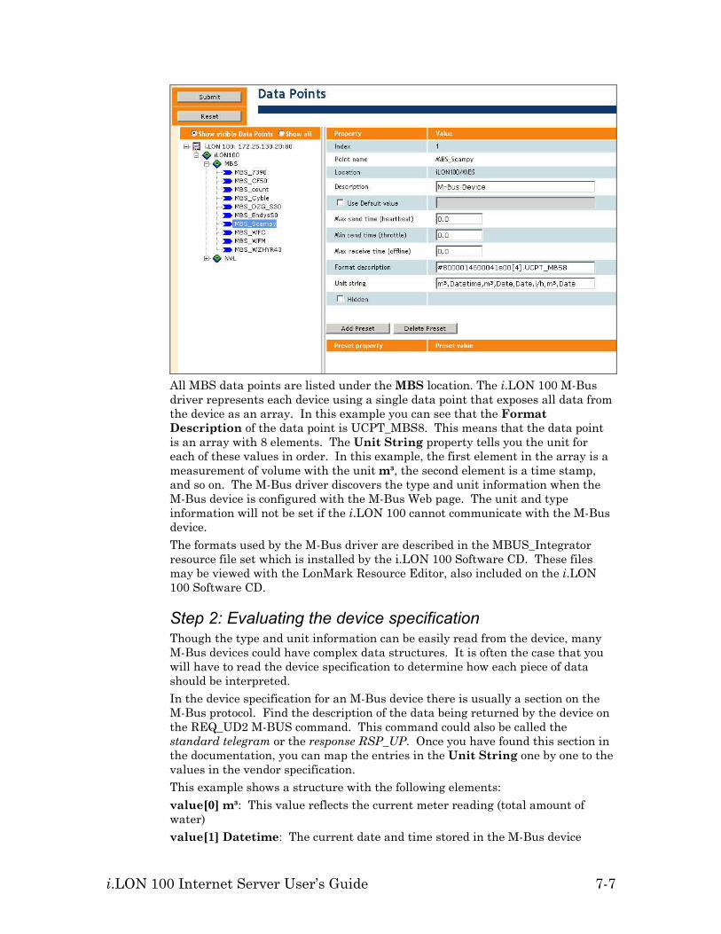
i.LON 100 Internet Server User’s Guide 7-7
All MBS data points are listed under the MBS location. The i.LON 100 M-Bus driver represents each device using a single data point that exposes all data from the device as an array. In this example you can see that the Format Description of the data point is UCPT_MBS8. This means that the data point is an array with 8 elements. The Unit String property tells you the unit for each of these values in order. In this example, the first element in the array is a measurement of volume with the unit m³, the second element is a time stamp, and so on. The M-Bus driver discovers the type and unit information when the M-Bus device is configured with the M-Bus Web page. The unit and type information will not be set if the i.LON 100 cannot communicate with the M-Bus device. The formats used by the M-Bus driver are described in the MBUS_Integrator resource file set which is installed by the i.LON 100 Software CD. These files may be viewed with the LonMark Resource Editor, also included on the i.LON 100 Software CD.
Step 2: Evaluating the device specification Though the type and unit information can be easily read from the device, many M-Bus devices could have complex data structures. It is often the case that you will have to read the device specification to determine how each piece of data should be interpreted. In the device specification for an M-Bus device there is usually a section on the M-Bus protocol. Find the description of the data being returned by the device on the REQ_UD2 M-BUS command. This command could also be called the standard telegram or the response RSP_UP. Once you have found this section in the documentation, you can map the entries in the Unit String one by one to the values in the vendor specification. This example shows a structure with the following elements: value[0] m³: This value reflects the current meter reading (total amount of water) value[1] Datetime: The current date and time stored in the M-Bus device
7-8 Using the Type Translator
value[2] m³: The meter reading at the last reference day. Reference days are configured by the installation tool for the device and define a fixed date or recurring pattern when data will be recorded. value[3] Date: The last reference day. Reference days are configured by the installation tool for the device and define a fixed date or recurring pattern when data will be recorded. value[4] Date: The next reference day value[5] l/h: The current flow of water value[6] m³: The meter reading at the end of the month value[7] Date: The date of last months reading
Step 3: Modifying the M-Bus Type Translator rules Once you have read the data sheet for your device and determined what each element in your M-Bus data point structure means, you can use an i.LON 100 Type Translator functional block to extract each item and map it to a network variable on the LonWorks network. The i.LON 100 ships with three generic Type Translator Rules for water, power, and thermal measurement which can be used as a starting point when integrating your own M-Bus devices. These rules are named MBS_HYDROMETER_SCAMPY_1, MBS_EMH_EIZ_EDWS_7390 and MBS_ACTARIS_CF50 respectively. The names of these rules are composed of the manufacturer and model number of actual devices for which these were designed. Other rule examples can be found on the i.LON 100 V1.1 CD in the Unsupported folder. You can view these built-in rules by opening the i.LON 100 Configuration Plug-in for an existing i.LON 100 and browsing to Type Translator Rules in the Applications pane as shown in the following figure.

i.LON 100 Internet Server User’s Guide 7-9
To integrate your device, you will either create a new Type Translator rule or duplicate one of the existing M-Bus rules. In the MBS_HYDROMETER_SCAMPY_1 rule, there is one input and two outputs. If the input data point for your device is not UCPT_MBUS8, add an input with the correct type to match your device. The M-Bus type definitions are stored in the MBUS_Integrator resource file set which by default is installed to $LonWorks$\Types\User\Echelon\MBUS_Integrator.fmt as shown below.

7-10 Using the Type Translator
This rule maps value[0] to an output network variable with the type SNVT_vol_f and value[5] to an output network variable with the type SNVT_flow_f#SI. You can use the i.LON 100 Configuration Plug-in to add more outputs to the rule if you would like to expose other data from the M-Bus device. For each output, add a rule that maps a data field from the M-Bus device to a SNVT. For example, to add a new output to expose the monthly reading from the M-Bus device sent on field 6, create the rule as shown in the following figure:
Step 4: Using the M-Bus Type Translator shapes in LonMaker There are predefined master Type Translator shapes in the i.LON 100 Stencil for three types of M-Bus devices: Water, Energy and Heating.
These shapes contain an output network variable for each output defined in the Type Translator rules. Add the appropriate shape to your LonMaker drawing,

i.LON 100 Internet Server User’s Guide 7-11
right-click on it, and then select Configure from the short-cut menu to open the i.LON 100 Configuration Plug-in with the Type Translator configuration window selected. To use your new rule, choose it from the list. The two predefined outputs will be selected by default. To select the input data points, click Name under the Inputs list and select the data point from the drop down list that appears as shown in the following figure.
The Name drop down list shows only data points of the appropriate type. If the i.LON 100 cannot communicate with the M-Bus device, it may not have set the data point type; in this case, your data point will not show up in this list. To add new output network variables to the M-Bus functional block using the LonMaker tool, drag an Output Network Variable shape from the i.LON 100 Shapes 1.1 stencil to the functional block (see the LonMaker documentation for more information. When creating network variables in LonMaker, you must have another network variable with the same type to act as a template. In the example above, the new output had the same type as the first output. In most cases, this process is simplified if you install the LonWorks devices that will be integrated before creating the output network variables. Note: The M-Bus driver represents all scalar values as double precision floating-point numbers (8 bytes). The use of 4 byte floating-point types such as SNVT_vol_f may exhibit a loss of precision when values become very large. The Pulse Counter output network variable nvoPcValue_1 is 8 bytes and may be used as a template to create output network variables with double precision floating point types, such as those found in the BAS_Controller resource file set of the i.LON 100 (UNVT_double_float, UNVT_elec_kwh_lf, and UNVT_power_lf).

i.LON 100 Internet Server User’s Guide 8-1
8
Using Pulse Counter Inputs
This chapter describes how to use the i.LON 100 server’s Pulse Counter to measure electrical energy, volume, rate or flow, or power.

8-2 Using Pulse Counter Inputs
Pulse Counter Overview The i.LON 100 device includes two pulse counter inputs. You can use these inputs to connect the i.LON 100 to a power meter or other device with a pulse output that does not include a LONWORKS interface. The i.LON 100 device contains 2 Pulse Counter functional blocks. The Pulse Counter functional blocks include the following input and output network variables:
nvoPcValue This changeable type output network variable
sends the cumulative pulse count data (i.e. the total number of pulse counts received in this time interval). This value will be calculated every time a pulse is received, but the value will not be sent to the network until the Time Interval (see below) expires or the state field of the nviPcTrigger network variable changes from Off (0) to On (1); polling this network variable at any time will return the most current value. The type of this network variable is set by the i.LON Configuration Software as described below.
nvoPcValueDif This changeable type output network variable sends the pulse rate. The type of this network variable is set by the i.LON Configuration Software as described below.
nviPcTrigger This SNVT_switch input network variable is used to synchronize the nvoPcValueDif network variable. When the state field of this network variable changes from Off (0) to On (1), the nvoPcValue and nvoPcValueDif values will be calculated and sent to the network and a new time interval is started.
Using the Pulse Counter To use pulse counter, follow these steps: 1. Open an existing LonMaker network or create a new LonMaker network as
described in the LonMaker User’s Guide. 2. Use an existing i.LON 100 device in the LonMaker network, or create and
commission a new i.LON 100 device. 3. Drag a Pulse Counter functional block shape from the i.LON 100 stencil to
the LonMaker drawing. The LonMaker New Functional Block wizard appears.
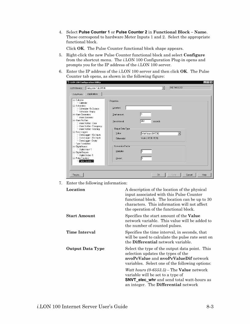
i.LON 100 Internet Server User’s Guide 8-3
4. Select Pulse Counter 1 or Pulse Counter 2 in Functional Block – Name. These correspond to hardware Meter Inputs 1 and 2. Select the appropriate functional block. Click OK. The Pulse Counter functional block shape appears.
5. Right-click the new Pulse Counter functional block and select Configure from the shortcut menu. The i.LON 100 Configuration Plug-in opens and prompts you for the IP address of the i.LON 100 server.
6. Enter the IP address of the i.LON 100 server and then click OK. The Pulse Counter tab opens, as shown in the following figure:
7. Enter the following information:
Location A description of the location of the physical input associated with this Pulse Counter functional block. The location can be up to 30 characters. This information will not affect the operation of the functional block.
Start Amount Specifies the start amount of the Value network variable. This value will be added to the number of counted pulses.
Time Interval Specifies the time interval, in seconds, that will be used to calculate the pulse rate sent on the Differential network variable.
Output Data Type Select the type of the output data point. This selection updates the types of the nvoPcValue and nvoPcValueDif network variables. Select one of the following options:
Watt hours (0-6553.5) – The Value network variable will be set to a type of SNVT_elec_whr and send total watt-hours as an integer. The Differential network
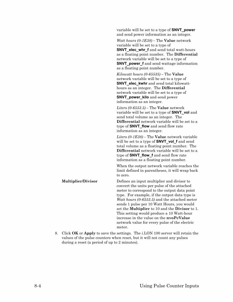
8-4 Using Pulse Counter Inputs
variable will be set to a type of SNVT_power and send power information as an integer.
Watt hours (0-1E38) – The Value network variable will be set to a type of SNVT_elec_whr_f and send total watt-hours as a floating point number. The Differential network variable will be set to a type of SNVT_power_f and send wattage information as a floating point number.
Kilowatt hours (0-65535) – The Value network variable will be set to a type of SNVT_elec_kwhr and send total kilowatt-hours as an integer. The Differential network variable will be set to a type of SNVT_power_kilo and send power information as an integer.
Liters (0-6553.5) – The Value network variable will be set to a type of SNVT_vol and send total volume as an integer. The Differential network variable will be set to a type of SNVT_flow and send flow rate information as an integer.
Liters (0-1E38) – The Value network variable will be set to a type of SNVT_vol_f and send total volume as a floating point number. The Differential network variable will be set to a type of SNVT_flow_f and send flow rate information as a floating point number.
When the output network variable reaches the limit defined in parentheses, it will wrap back to zero.
Multiplier/Divisor Defines an input multiplier and divisor to convert the units per pulse of the attached meter to correspond to the output data point type. For example, if the output data type is Watt hours (0-6553.5) and the attached meter sends 1 pulse per 10 Watt Hours, you would set the Multiplier to 10 and the Divisor to 1. This setting would produce a 10 Watt-hour increase in the value on the nvoPcValue network value for every pulse of the electric meter.
8. Click OK or Apply to save the settings. The i.LON 100 server will retain the values of the pulse counters when reset, but it will not count any pulses during a reset (a period of up to 2 minutes).

i.LON 100 Internet Server User’s Guide 9-1
9
Using the Analog Function Block
This chapter describes how to use the i.LON 100 server’s Analog Function Block application to perform statistical, arithmetic, or logical operations on input values and send output values.

9-2 Using the Analog Function Block
Analog Function Block Overview The i.LON 100 device includes twenty analog function blocks. You can use these functional blocks to perform statistical, arithmetic, or logical operations on data points. The i.LON 100 device contains 20 Analog Function Block functional blocks. The Analog Function Blocks include the following input and output network variables:
nvoAfbDropOut This SNVT_count type output network variable
provides a count of data points that are currently offline.
nvoAfbOutput This dynamic, changeable type output network variable is used to send the output of the Analog Function Block. By default, the type is set to SNVT_temp_f. The type must be set to a scalar type or to SNVT_switch.
nviAfbInputA/B These changeable-type input network variables provide input values to the analog function block. The analog function block can be configured to operate on these values or to compare one of them to the nviAfbCompare network variable value. The comparison function can be configured as described in Comparing Data Points, below.
nviAfbCompare This dynamic changeable-type input network variable provides a value to be compared to the nviAfbInput network variable value. This network variable must have the same type as the nviAfbInput network variable. The input and compare functional blocks must be scalar types.
Using the Analog Function Block To use the analog function block, follow these steps: 1. Open an existing LonMaker network or create a new LonMaker network as
described in the LonMaker User’s Guide. 2. Use an existing i.LON 100 device in the LonMaker network, or create and
commission a new i.LON 100 device. 3. Drag an Analog Function Block functional block shape from the i.LON 100
stencil to the LonMaker drawing. The LonMaker New Functional Block wizard appears.
4. Select one of the 20 available Analog Function Blocks in Functional Block – Name.

i.LON 100 Internet Server User’s Guide 9-3
Click OK. The Analog Function Block functional block shape appears. 5. Right-click the new Analog Function Block functional block and select
Configure from the shortcut menu. The i.LON 100 Configuration Plug-in opens and prompts you for the IP address of the i.LON 100 server.
6. Enter the IP address of the i.LON 100 server and then click OK. The Analog Function Block dialog opens, as shown in the following figure:
7. Enter the following information:
Description Enter a description of the analog function block.
Output Override Behavior Determine the behavior of output data points on the analog function block functional block when it is put into override. Available options are:
Retain Last Value – The output data points continue to send their most recent value before the functional block was put into override.
Set Specified Value – The output data points send the specified value when the functional block is in override. You must ensure that the given value is valid.
Set Default Value – The output data points send their default values.
8. See one of the following sections corresponding to what function you want the analog function block to perform (click Help for more information about any options that are not discussed below):

9-4 Using the Analog Function Block
Adding, Averaging, or Selecting the Minimum or Maximum of Two or More Values
To perform a arithmetic or statistical operation on two or more values using the analog function block, follow these steps: 1. Click Inputs under the analog function block on the Applications list. The
Inputs dialog opens, as shown in the following figure:
2. By default, the nviAfbInputA and nviAfbInputB data points will appear
in the Input Data Points list. Click Add to add additional data points to the list using the Add Data Points dialog. All data points must be scalar types (although data points of different types may yield unpredictable results due to differing scaling factors).
3. Click Outputs under the analog function block on the Applications list. The Outputs dialog opens, as shown in the following figure:
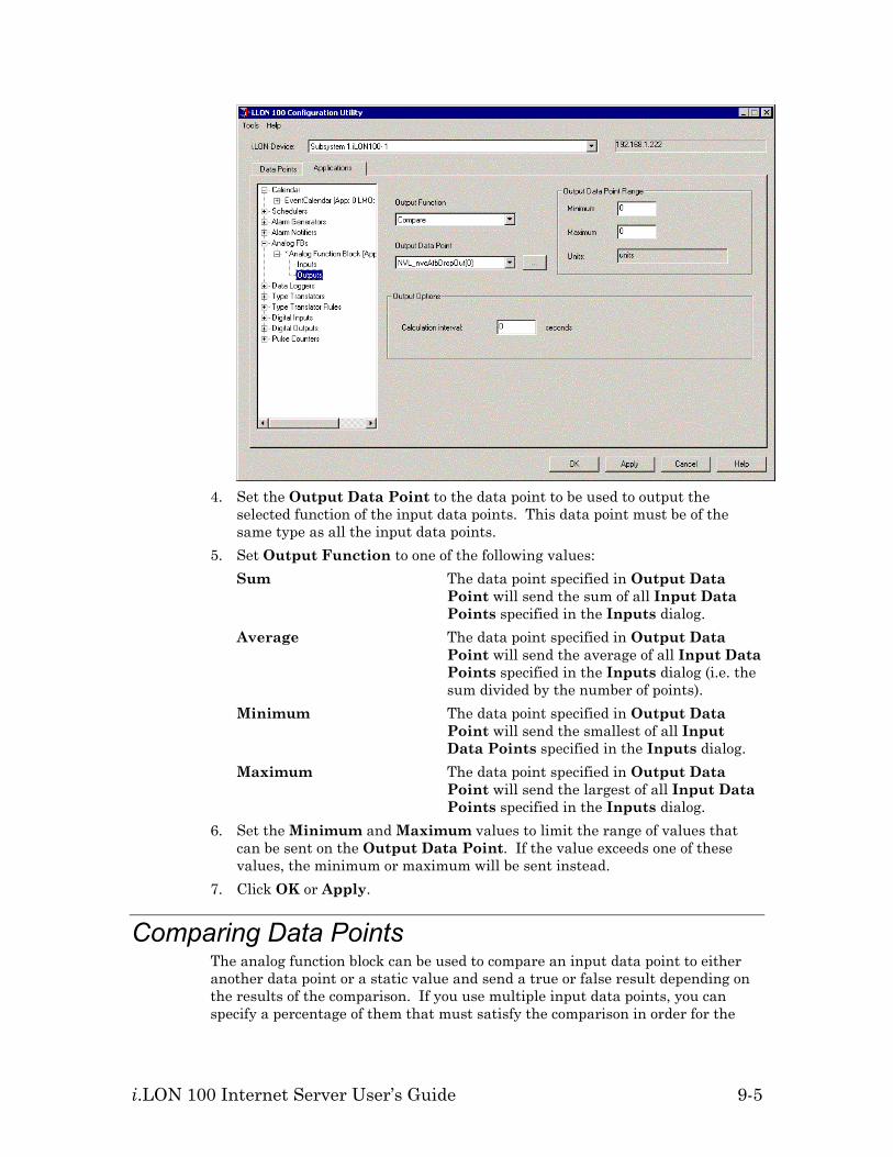
i.LON 100 Internet Server User’s Guide 9-5
4. Set the Output Data Point to the data point to be used to output the
selected function of the input data points. This data point must be of the same type as all the input data points.
5. Set Output Function to one of the following values: Sum The data point specified in Output Data
Point will send the sum of all Input Data Points specified in the Inputs dialog.
Average The data point specified in Output Data Point will send the average of all Input Data Points specified in the Inputs dialog (i.e. the sum divided by the number of points).
Minimum The data point specified in Output Data Point will send the smallest of all Input Data Points specified in the Inputs dialog.
Maximum The data point specified in Output Data Point will send the largest of all Input Data Points specified in the Inputs dialog.
6. Set the Minimum and Maximum values to limit the range of values that can be sent on the Output Data Point. If the value exceeds one of these values, the minimum or maximum will be sent instead.
7. Click OK or Apply.
Comparing Data Points The analog function block can be used to compare an input data point to either another data point or a static value and send a true or false result depending on the results of the comparison. If you use multiple input data points, you can specify a percentage of them that must satisfy the comparison in order for the

9-6 Using the Analog Function Block
analog function block or output a TRUE value. To compare data points, follow these steps: 1. Click Inputs under the analog function block on the Applications list. The
Inputs dialog opens, as shown in the following figure:
2. By default, the nviAfbInput data point will appear in the Input Data
Points list. Click Add to add additional data points to the list using the Add Data Points dialog.
3. Set Compare Function to determine how the input data points will be compared to the compare data point or the threshold value. Click Help for a description of the comparison functions.
4. Set Compare With to determine what value will be compared against the input data points. Select Threshold Value to enter a static value to be used for comparison. Select Compare Data Point to compare the input data points to another data point value. By default, this is set to the nviAfbCompare data point, but you can select any data point that matches the type of the input data points.
5. If you are comparing multiple data points, set Majority Value to the percentage of data points that must satisfy the comparison in order for the analog function block to output a TRUE value.
6. Click Outputs under the analog function block on the Applications list. The Outputs dialog opens, as shown in the following figure:

i.LON 100 Internet Server User’s Guide 9-7
7. Set Output Function to one of the following values:
Compare The data point specified in Output Data Point will send a true value if the comparison specified in the Inputs tab evaluates as true. For multiple data points, Majority Value is used to determine what percentage of input data points must satisfy the condition for the Output Data Point to send a true value.
AND If all data points specified in Input Data Points in the Inputs dialog evaluate as true, the Output Data Point will send a true value.
OR If any data points specified in Input Data Points in the Inputs dialog evaluate as true, the Output Data Point will send a true value.
8. Set Output Data Point to the data point to be used to output the TRUE or FALSE value. This data point must be of the SNVT_Switch type.

i.LON 100 Internet Server User’s Guide A-1
Appendix A
Troubleshooting
This appendix can be used to diagnose common problems that occur with the i.LON 100 device.

A-2 Troubleshooting
When I run the i.LON 100 Configuration Plug-in I get an error stating that I could not communicate with the i.LON 100 • Verify that the WSDL file is not password protected. Protection is defined in
the webparams.dat file located at the root of the i.LON 100's flash disk. • Verify that the IP communication path to the i.LON 100 is intact. (Try
pinging the i.LON 100) I have created NVE style points and although I can see them in the plug-in and reference them using the SOAP/XML interface I can not reference them within my Web pages. • The i.LON 100 Web server does not allow NVE tag names with spaces. Be
sure your tag names do not have spaces. The SOAP/XML server and the plug-in do allow spaces under some conditions, but the best practice is never to include spaces in NVE names.
I can't make my i.LON 100 send an email message. What am I doing wrong? • Emails are sent as a result of alarm conditions. Verify that the alarm
condition actually triggers and that the email *should* be sent. After changing the type of a data point using Configuration Plug-in or the LonMaker browser, the data point starts showing incorrect data. • The LNS Data Server may be using old format data. Close and restart all
LNS applications. The i.LON 100 exhibits problems due to a low-memory condition. This could be indicated by one or more of the following: “out-of-memory” messages, slow network access, application performance problems, or even an unexpected reboot. • Reduce the number of Alarm Notifiers and/or the size limit of the alarm
Summary Logs (which are kept in RAM). • Reduce the number of Web clients that are simultaneously accessing the
i.LON 100. • If you are making calls to the SOAP interface on the i.LON 100, refer to the
i.LON 100 Programmer’s Guide for specific recommendations on limiting SOAP messages.
I am having trouble getting the upgrade procedure to work. If you are having trouble using the i.LON 100 upgrade tool, you can manually upgrade a configured i.LON 100 device to a later version without losing your configuration, by following these steps: 1. On your computer, install the new version of the i.LON 100 software from the
version i.LON 100 CD. 2. Using an FTP client, back up the entire contents of your i.LON 100 device to
your computer. 3. Using an FTP client, delete all files from the /Modules directory on the i.LON
100 device. 4. Using an FTP client, overwrite the files on the i.LON 100 device with the
i.LON 100 image installed on your computer in step 1. By default, this image is located at C:\LonWorks\iLON100\Images\iLON100 x.xx (where x.xx is the latest version number).
5. Using an FTP client, restore the following backed up files to their old locations on the i.LON 100:

i.LON 100 Internet Server User’s Guide A-3
/config/Software/Dataserver/DP_NVL.xml /config/Software/rni.xml
6. Reboot the i.LON 100. 7. If the new version of the software includes a new bootrom, update the
bootrom as described in Appendix A of the i.LON 100 User’s Guide: Installing, Connecting, and Configuring the i.LON 100.