im in a r y - upper great plains transportation institute ... 1 date bridge engineer department of...
TRANSCRIPT
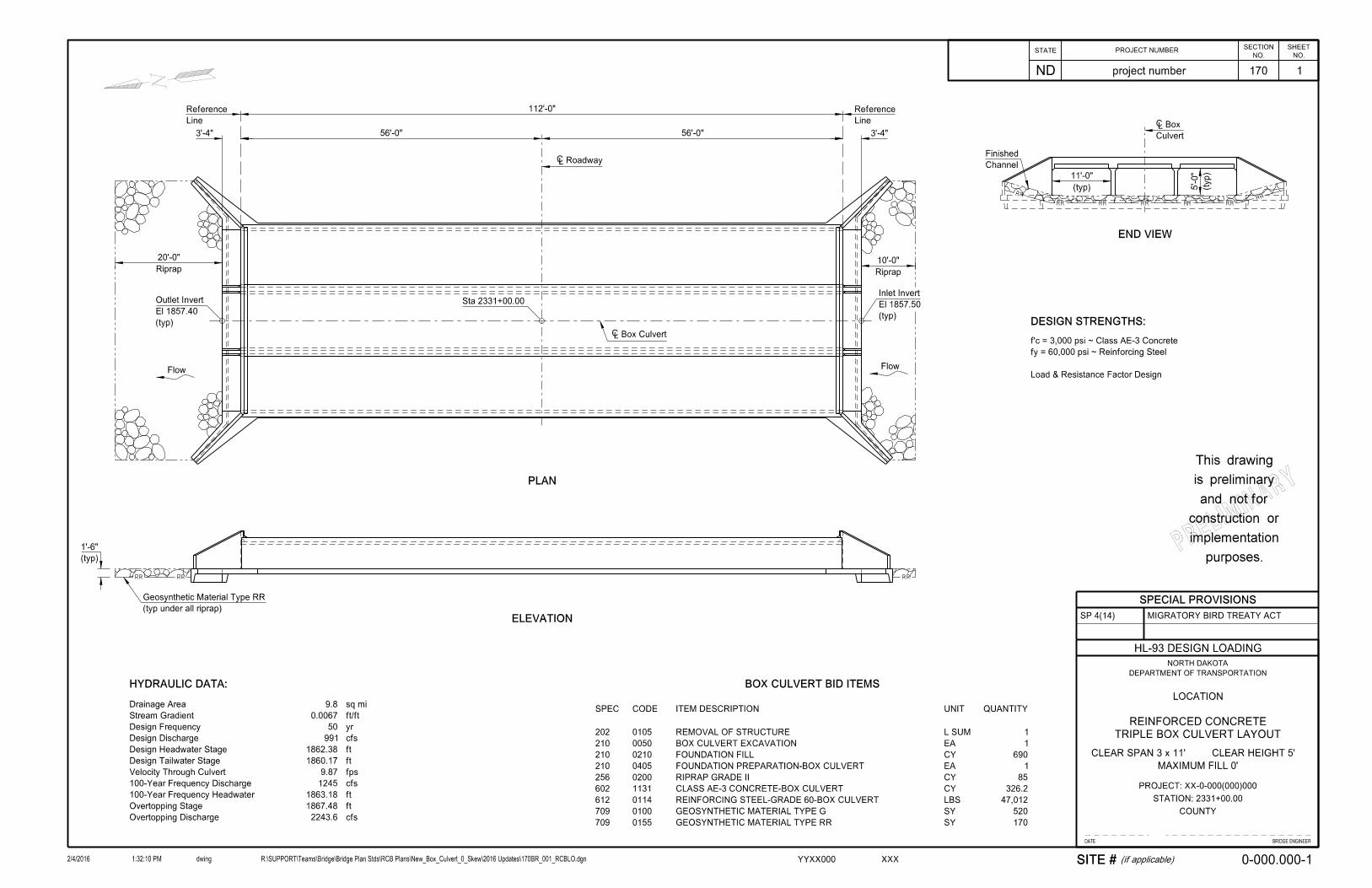
ELEVATION
‘ Roadway
‘ Box Culvert
Line
Reference
Line
Reference
Sta 2331+00.00
PLAN
112’-0"
56’-0" 56’-0"3’-4" 3’-4"
END VIEW
Culvert
‘ Box
Channel
Finished
DESIGN STRENGTHS:
Load & Resistance Factor Design
fy = 60,000 psi ~ Reinforcing Steel
f’c = 3,000 psi ~ Class AE-3 Concrete
Riprap
10’-0"Riprap
20’-0"
(typ)
El 1857.40
Outlet Invert
(typ)
El 1857.50
Inlet Invert
(typ)
1’-6"
FlowFlow
SITE # (if applicable)
HYDRAULIC DATA:
Overtopping Discharge
Overtopping Stage
100-Year Frequency Headwater
100-Year Frequency Discharge
Velocity Through Culvert
Design Tailwater Stage
Design Headwater Stage
Design Discharge
Design Frequency
Stream Gradient
Drainage Area
2243.6
1867.48
1863.18
1245
9.87
1860.17
1862.38
991
50
0.0067
9.8
cfs
ft
ft
cfs
fps
ft
ft
cfs
yr
ft/ft
sq mi
(typ)
11’-0"
(typ)
5’-0"
(typ under all riprap)
Geosynthetic Material Type RR
BOX CULVERT BID ITEMS
SPEC CODE ITEM DESCRIPTION UNIT QUANTITY
170
520
47,012
326.2
85
1
690
1
1
SY
SY
LBS
CY
CY
EA
CY
EA
L SUM
GEOSYNTHETIC MATERIAL TYPE RR
GEOSYNTHETIC MATERIAL TYPE G
REINFORCING STEEL-GRADE 60-BOX CULVERT
CLASS AE-3 CONCRETE-BOX CULVERT
RIPRAP GRADE II
FOUNDATION PREPARATION-BOX CULVERT
FOUNDATION FILL
BOX CULVERT EXCAVATION
REMOVAL OF STRUCTURE
0155
0100
0114
1131
0200
0405
0210
0050
0105
709
709
612
602
256
210
210
210
202
STATENO.
ND
PROJECT NUMBERSHEET
NO.
SECTION
2/4/2016 dwing R:\SUPPORT\Teams\Bridge\Bridge Plan Stds\RCB Plans\New_Box_Culvert_0_Skew\2016 Updates\170BR_001_RCBLO.dgn1:32:10 PM
project number 170
XXXYYXX000
0-000.000-1
1
DATE BRIDGE ENGINEER
DEPARTMENT OF TRANSPORTATION
NORTH DAKOTA
LOCATION
CLEAR HEIGHT 5’
COUNTY
PROJECT: XX-0-000(000)000
HL-93 DESIGN LOADING
REINFORCED CONCRETE
STATION: 2331+00.00
TRIPLE BOX CULVERT LAYOUT
CLEAR SPAN 3 x 11’
MAXIMUM FILL 0’
PRELIMINARY
purposes.
implementation
construction or
and not for
is preliminary
This drawing
SPECIAL PROVISIONS
MIGRATORY BIRD TREATY ACTSP 4(14)

NOTES
2/4/2016 1:16:28 PM R:\SUPPORT\Teams\Bridge\Bridge Plan Stds\RCB Plans\New_Box_Culvert_0_Skew\2016 Updates\170BR_002_NOTES.docm
STATE PROJECT NO. SECTION
NO. SHEET
NO.
ND project number 170 2
0-000.000-2
100 SCOPE OF WORK: Work at this site consists of removing an existing structure and building a new triple barrel 11' x 5' x 112'-0" reinforced concrete box culvert.
202 REMOVAL OF STRUCTURE: The existing structure is a 2-span concrete slab bridge, 36'-0" long with a clear roadway width of 26'-0". Include all work required to remove the bridge in the contract unit price for “Removal of Structure”.
Submit SFN 17987 Asbestos Notification of Demolition and Renovation to the North
Dakota Department of Health 10 days before beginning removal of concrete. 210 ORDINARY BACKFILL: Compact material as specified in Section 203.04 E.2.a, “ND T 180.” 602 CONCRETE: Provide aggregate for concrete that meets the requirements of Section
802.01C.2, “Course Aggregate” and Section 802.01C.3, “Fine Aggregate”. 602 CONCRETE: Cast the following elements of each section in one continuous run:
1. Floor slab and wing footings 2. Each intermediate wall up to the bottom of fillets 3. Each sidewall up to the bottom of fillets with its
adjacent wings complete to the top 4. Roof slab and parapets
Allow the concrete in the walls to set at least two hours before the roof slab is poured.
602 CURING CONCRETE: Wet cure all concrete surfaces not covered by forms. Cover the concrete with a double thickness of burlap. Maintain surface moisture between the final finish and placement of burlap by periodic applications of a light fog spray of water. Keep the burlap continuously moist until the end of the curing period.
612 REINFORCING STEEL: When the distance between end bars is not evenly divisible by bar spacing, adjust the odd distance by a few irregular spaces near the center, not at the ends of the culvert. Dimensions of bent bars are given out to out.
1:11:1
20:120:1
HBP
(typ)
4’-0"
Sta 2331+00.0
‘ Box Culvert
(typ)
2’-0"
Fill
Foundation
1’-0"
(typ)
5’-0"
80’-0"80’-0" 55’-0"
(typ)
2’-6"
(typ)
7’-3"
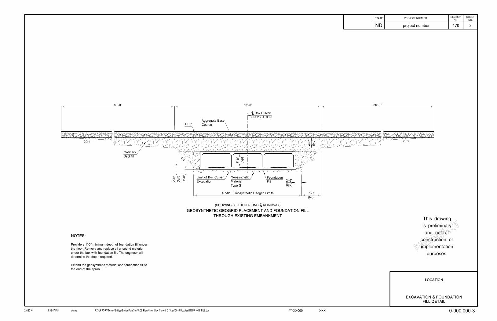
(SHOWING SECTION ALONG ‘ ROADWAY)
Backfill
Ordinary
Course
Aggregate Base
Excavation
Limit of Box Culvert
THROUGH EXISTING EMBANKMENT
GEOSYNTHETIC GEOGRID PLACEMENT AND FOUNDATION FILL
NOTES:
the end of the apron.
Extend the geosynthetic material and foundation fill to
determine the depth required.
under the box with foundation fill. The engineer will
the floor. Remove and replace all unsound material
Provide a 1’-0" minimum depth of foundation fill under
40’-8" ~ Geosynthetic Geogrid Limits
Type G
Material
Geosynthetic
STATENO.
ND
PROJECT NUMBERSHEET
NO.
SECTION
2/4/2016 dwing R:\SUPPORT\Teams\Bridge\Bridge Plan Stds\RCB Plans\New_Box_Culvert_0_Skew\2016 Updates\170BR_003_FILL.dgn1:32:47 PM
project number 170
XXXYYXX000
LOCATION
3
0-000.000-3
EXCAVATION & FOUNDATION
FILL DETAIL
PRELIMINARY
purposes.
implementation
construction or
and not for
is preliminary
This drawing
S4
Sym about ‘
3"2"
1’-0" 1’-0" 1’-0" 1’-0"1’-2"
5’-2"
3"
"2
12
"8
72
"4
11
1’-6"
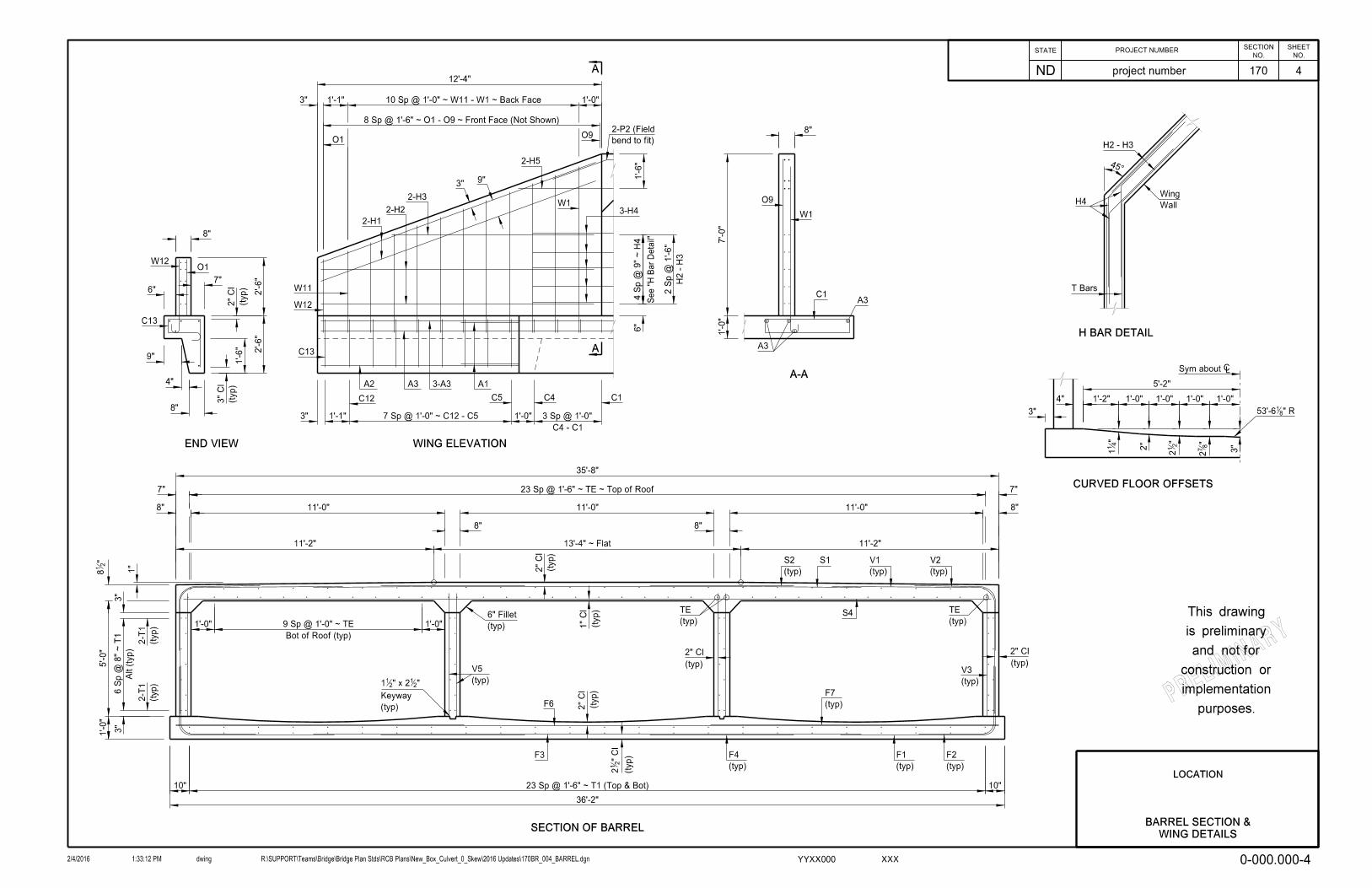
WING ELEVATION
A
A
F6
S1
(typ)
2-T
1
(typ)
2-T
1
8"
1’-1"
12’-4"
1’-0"
3 Sp @ 1’-0"
9"3"
2-H5
2-H1
2-H2
2-H3
3"
1’-0"1’-1"3"
3"
3"
1’-0"
5’-0"
"2
18 1"
Alt (ty
p)
6 S
p @ 8" ~ T
1
bend to fit)
2-P2 (Field
8"
35’-8"
11’-0"11’-0" 11’-0"
(typ)
V2
(typ)
V1
(typ)
S2
(typ)
V3
(typ)
TE
(typ)
6" Fillet
(typ)
V5
23 Sp @ 1’-6" ~ T1 (Top & Bot)10"
36’-2"
10"
(typ)
F7
(typ)
F4
(typ)
F1
(typ)
F2
SECTION OF BARREL
F3
O1O9
W1
W11
C5
A2 A3 3-A3 A1
W12
3-H4
Bot of Roof (typ)
9 Sp @ 1’-0" ~ TE
C12 C4 C1
C4 - C1
" R8153’-6
1’-0" 1’-0"
10 Sp @ 1’-0" ~ W11 - W1 ~ Back Face
8 Sp @ 1’-6" ~ O1 - O9 ~ Front Face (Not Shown)
7 Sp @ 1’-0" ~ C12 - C5
(typ)
Keyway
"21" x 22
11
7" 7"23 Sp @ 1’-6" ~ TE ~ Top of Roof
13’-4" ~ Flat 11’-2"11’-2"
8" 8"
6"
4 S
p @ 9" ~ H
4
(typ)
TE
H2 - H
3
2 S
p @ 1’-6"
See "
H B
ar
Detail"
45°
Wall
WingH4
T Bars
H2 - H3
H BAR DETAIL
2"
Cl
2" Cl
(typ) (typ)
2" Cl
C13
(typ)
(typ)
(typ)
(typ)
END VIEW
1’-6"
6"
7"
8"
C13
W12O1
3"
Cl
(typ)
(typ)
2"
Cl
2’-6"
2’-6"
A-A
8"
W1
O9
A3
A3
7’-0"
1’-0"
C1
4"
9"
8"
2"
Cl
1"
Cl
" Cl
21
2
CURVED FLOOR OFFSETS
4"
PRELIMINARY
purposes.
implementation
construction or
and not for
is preliminary
This drawing
BARREL SECTION &
WING DETAILS
STATENO.
ND
PROJECT NUMBERSHEET
NO.
SECTION
2/4/2016 dwing R:\SUPPORT\Teams\Bridge\Bridge Plan Stds\RCB Plans\New_Box_Culvert_0_Skew\2016 Updates\170BR_004_BARREL.dgn1:33:12 PM
project number 170
XXXYYXX000
LOCATION
0-000.000-4
4
3’-4"
"2
13’-1
2-A1 C14
C13
(Top)
F9
(Top)
F8
(Bot)
F10
(Top)
A3
(Bot)
A3(Bot)
A2
(Bot)
F4
(Bot)
F3
(Top)
F7
(Top)
F6
(Bot)
F1
(Bot)
F2
"2
1
C5
4"
F1, F3 & F
6 S
p @ 9"
F2, F4 & F
7 S
p @ 9"
‘ Box Culvert
Sym about
Refere
nce Line
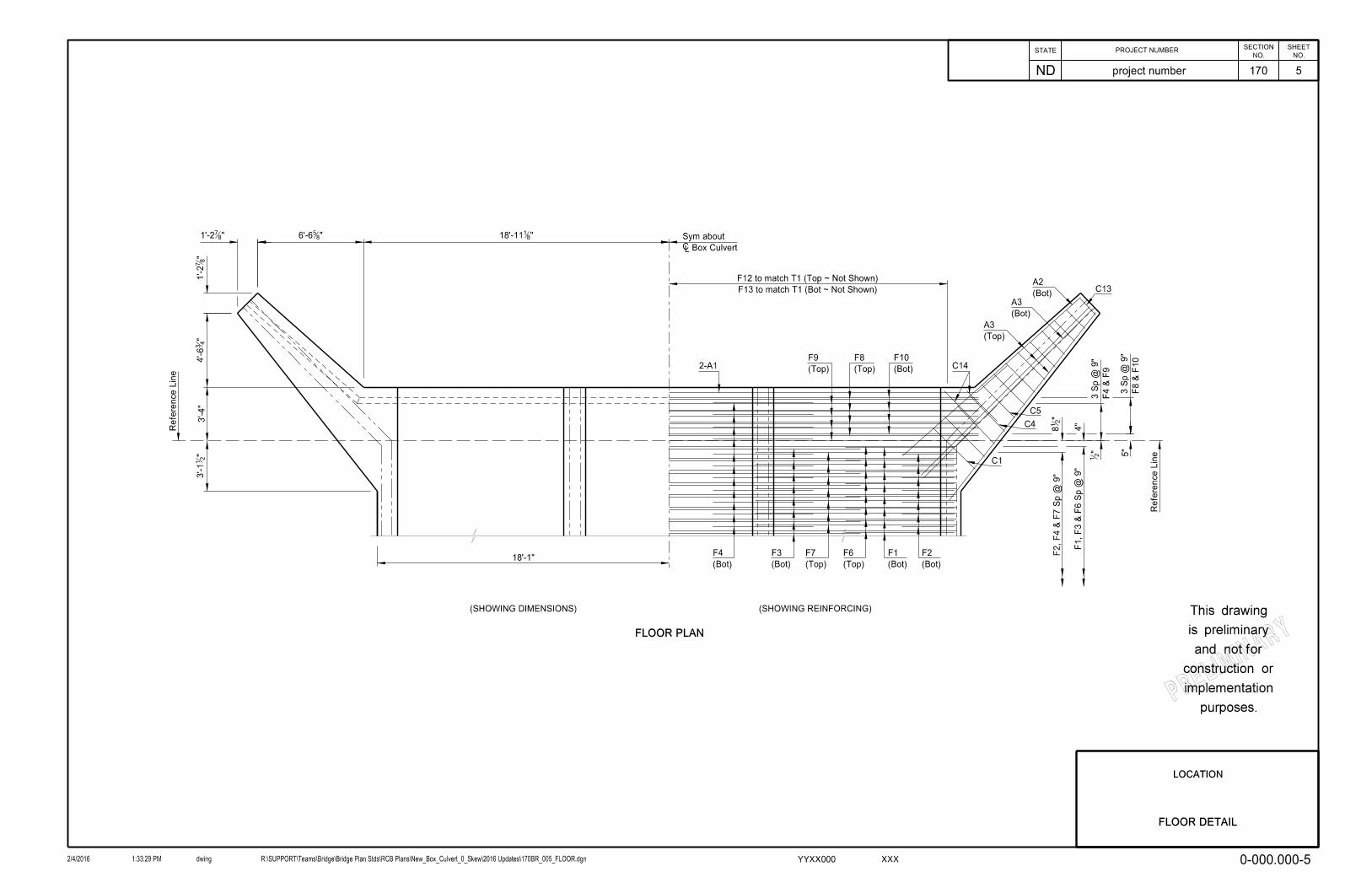
18’-1"
"4
34’-6
"8
71’-2
"856’-6"8
71’-2 "8118’-11
C1
C4
(SHOWING DIMENSIONS) (SHOWING REINFORCING)
FLOOR PLAN
F4 & F
9
3 S
p @ 9"
F8 & F
10
3 S
p @ 9"
F13 to match T1 (Bot ~ Not Shown)
F12 to match T1 (Top ~ Not Shown)
Refere
nce Line
5"
"2
18
FLOOR DETAIL
STATENO.
ND
PROJECT NUMBERSHEET
NO.
SECTION
2/4/2016 dwing R:\SUPPORT\Teams\Bridge\Bridge Plan Stds\RCB Plans\New_Box_Culvert_0_Skew\2016 Updates\170BR_005_FLOOR.dgn1:33:29 PM
project number 170
XXXYYXX000
LOCATION
PRELIMINARY
purposes.
implementation
construction or
and not for
is preliminary
This drawing
5
0-000.000-5

INNER WALL
LONGITUDINAL SECTIONS
OUTER WALL
4’-0"
6"
6"
2-F11
1’-8"
T1
T1 2-T1
2-T3
2-V7
T4
2-V6
T82-V8
3’-4"
Reference Line
P1TE
P2
4’-6"
4"
V3 Sp @ 1’-0" (Not Shown)
V1 Sp @ 9"
F1 Sp @ 9"
F13
PE
P3
PE
F12
P1 TE
6"
3"
3"
2-T1T1
Reference Line
1’-0" V5 Sp @ 1’-0"
6 S
p @ 8" ~ T
1 (
Alt)
(typ)
V2
(typ)
V1
(typ)
F1
(typ)
F2
F13
F12
V2 Sp @ 9"
2-V5
See "Parapet Detail" See "Parapet Detail"
V7 - V6
1’-0"
A1
PARAPET DETAIL
"2
14
1’-3"
2’-0"
9"
1’-0"
6"
9"
‘ S
ection
End S
ection
"2
19
"2
18
"218
(typ)
" Cl211
F2 Sp @ 9""218
4"
(typ)
" Cl211
11"
T3 - T
8 (
Alt)
5 S
p @ 8"
3"
PRELIMINARY
purposes.
implementation
construction or
and not for
is preliminary
This drawing
STATENO.
ND
PROJECT NUMBERSHEET
NO.
SECTION
2/4/2016 dwing R:\SUPPORT\Teams\Bridge\Bridge Plan Stds\RCB Plans\New_Box_Culvert_0_Skew\2016 Updates\170BR_006_WALLS.dgn1:33:46 PM
project number 170
XXXYYXX000
LOCATION
0-000.000-6
6
WALL DETAILS &
PARAPET DETAIL
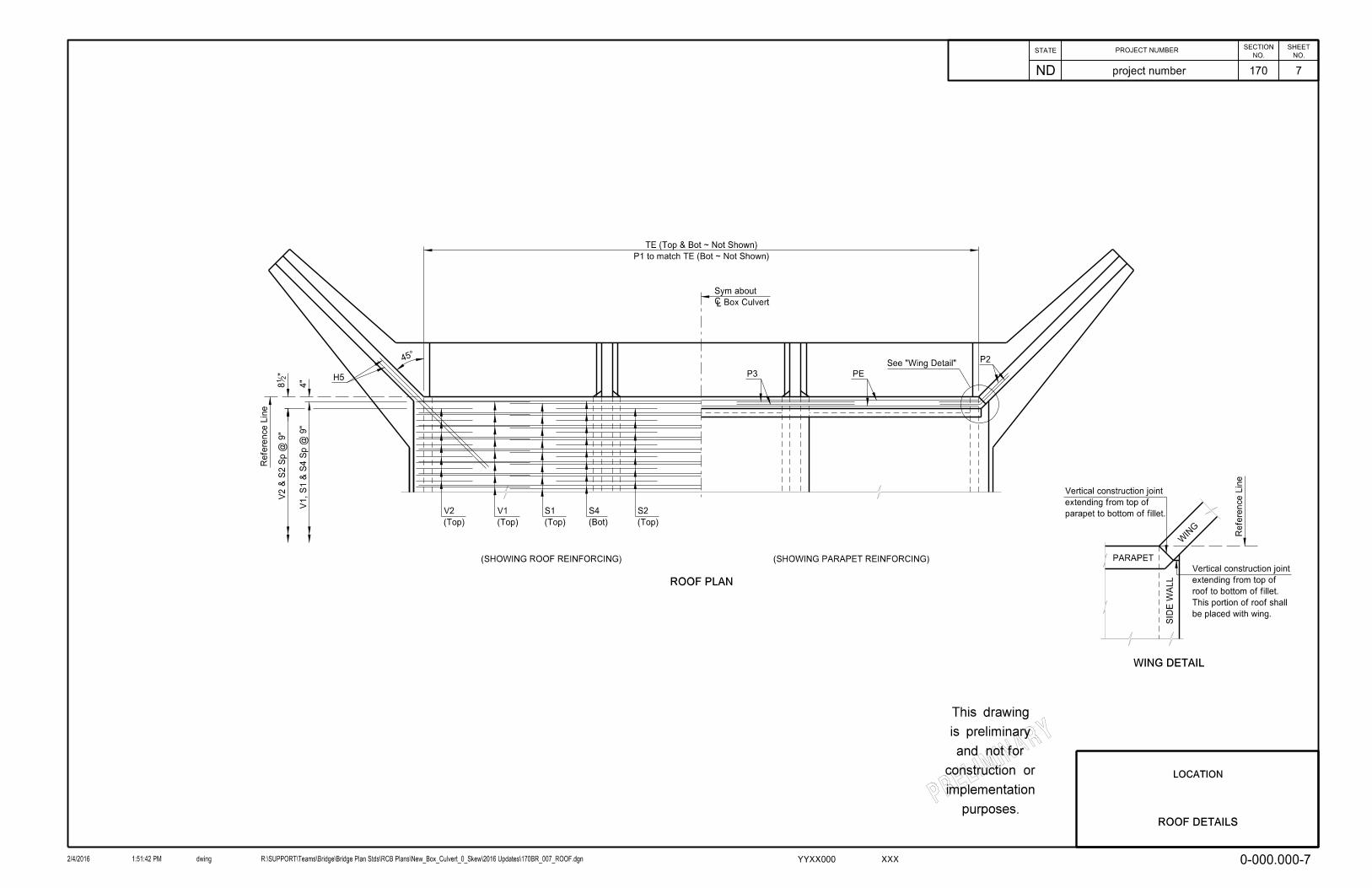
ROOF PLAN
(SHOWING ROOF REINFORCING) (SHOWING PARAPET REINFORCING)
Refere
nce Line
V2 & S
2 S
p @ 9"
V1, S1 & S
4 S
p @ 9"
4"
(Top)
V2
(Top)
V1
(Top)
S1
(Bot)
S4
(Top)
S2
H5
P245̂
‘ Box Culvert
Sym about
P3 PE
See "Wing Detail"
parapet to bottom of fillet.
extending from top of
Vertical construction joint
Refere
nce Line
be placed with wing.
This portion of roof shall
roof to bottom of fillet.
extending from top of
Vertical construction joint
PARAPET
WIN
G
SID
E W
ALL
WING DETAIL
"2
18
P1 to match TE (Bot ~ Not Shown)
TE (Top & Bot ~ Not Shown)
ROOF DETAILS
PR
ELIMINARY
purposes.
implementation
construction or
and not for
is preliminary
This drawing
STATENO.
ND
PROJECT NUMBERSHEET
NO.
SECTION
2/4/2016 dwing R:\SUPPORT\Teams\Bridge\Bridge Plan Stds\RCB Plans\New_Box_Culvert_0_Skew\2016 Updates\170BR_007_ROOF.dgn1:51:42 PM
project number 170
XXXYYXX000
LOCATION
0-000.000-7
7
BAR LIST (CONSTANT)
SHAPELENGTHNO.SIZEMARK
BAR LIST (VARIABLE)
MARK SIZE NO. LENGTH SHAPE
4 7’-7"
7’-4"
6’-11"
6’-7"
6’-2"
5’-10"
5’-6"
5’-1"
4’-9"
4’-5"
4’-0"
3’-7"
BENT
4 BENT
4 BENT
4 BENT
4 BENT
4 BENT
4 BENT
4 BENT
4 BENT
W10 4 BENT
W11 4 BENT
W12 4 BENT
4 4
BENT
4 4
BENT
4 4
BENT
4 4
BENT
4 4
BENT
4 4
BENT
4 4
BENT
4 4
BENT
4 4
BENT
C10
4 4
BENT
C11
4 8
BENT
6 16 STR.
4 16 STR.
4 8 STR.
4 60 BENT
6 8 STR.
4 4 SETS
4
5
4
4
4
4
4
5
4
4
5
6
5
T1 4
V1
V2
V3
V5
F1
F2
F3
F4
F6
F7
S1
S2
S4
W1
W2
W3
W4
W5
W6
W7
W8
W9
C1
C2
C3
C4
C5
C6
C7
C8
C9
H1
H2
H3
H4
H5
O1-O9
8’-0"
9’-0"
8’-8"
8’-4"
8’-0"
7’-6"
7’-2"
6’-10"
6’-6"
6’-0"
4’-9"
12’-8"
8’-10"
6’-0"
41’-8"
BENT
BENT296
STR.226
STR.456
BENT
BENT296
STR.
STR.
STR.
STR.
STR.
STR.
STR.
300
300
150
312
150
296
150
296
150
STR.
12’-3"
6’-0"
5’-4"
5’-4"
9’-6"
6’-0"
23’-9"
6’-3"
35’-8"
12’-6"
23’-9"
6’-3"
35’-0"
4
4
4
4
4
4
4
4
4
4
4
4
11’-11"
9’-6"
6
16
STR.
STR.
A1
A2
A3
22’-5"
14’-9"
8 STR.
P1
P2
P3
4’-7"
7’-4"
STR.
4 STR.
8 STR.
V6
V7
V8
3’-9"
5’-7"
4
4
6
6
6
6
6
8
8
8
8
72
4
BENT
BENT
BENT
8’-9"
5’-0"
2’-5"
STR.
4 STR.
8 STR.
F8
F9
38’-4"
38’-4"
4 8
8 38’-4"
4
48 STR.
5’-6"
4’-7"
6 8
48 6’-4"
F10
F11
F12
F13
4
4
BENT
BENT
4
STR.16’-6"
4’-8"
4
T3 8
4 SETS
STR.
PE 6 8 18’-2" STR.
TE 4 BENT
C12
C13
C14
BENT
BENT
BENT
4 4 8’-4"
4 4 8’-8"
4 4 9’-0"
84
60
112’-9"
113’-4"
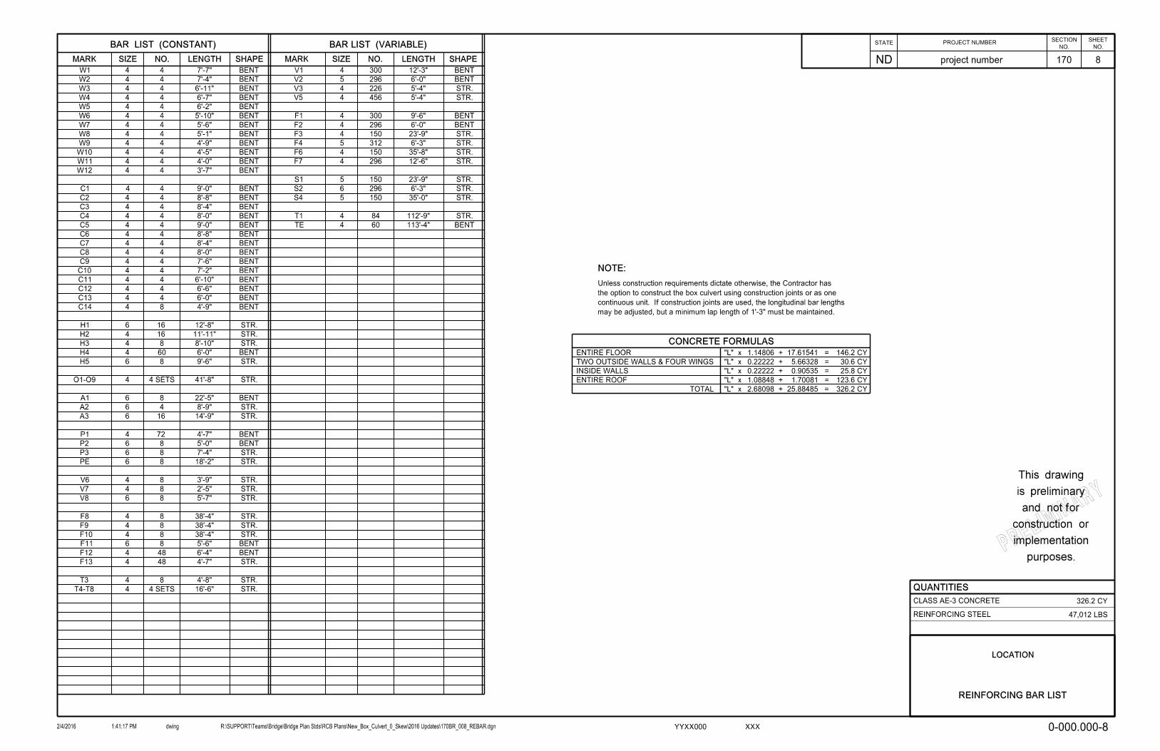
CONCRETE FORMULAS
ENTIRE FLOOR
TWO OUTSIDE WALLS & FOUR WINGS
INSIDE WALLS
ENTIRE ROOF
TOTAL
"L" x
"L" x
"L" x
"L" x
"L" x
1.14806 + 17.61541 =
2.68098 + 25.88485 =
146.2 CY
30.6 CY
25.8 CY
123.6 CY
326.2 CY
STR.
may be adjusted, but a minimum lap length of 1’-3" must be maintained.
continuous unit. If construction joints are used, the longitudinal bar lengths
the option to construct the box culvert using construction joints or as one
Unless construction requirements dictate otherwise, the Contractor has
NOTE:
0.22222 + 5.66328 =
0.22222 + 0.90535 =
1.08848 + 1.70081 =
T4-T8
PRELIMINARY
purposes.
implementation
construction or
and not for
is preliminary
This drawing
REINFORCING BAR LIST
STATENO.
ND
PROJECT NUMBERSHEET
NO.
SECTION
2/4/2016 dwing R:\SUPPORT\Teams\Bridge\Bridge Plan Stds\RCB Plans\New_Box_Culvert_0_Skew\2016 Updates\170BR_008_REBAR.dgn1:41:17 PM
project number 170
XXXYYXX000
LOCATION
8
0-000.000-8
QUANTITIES
CLASS AE-3 CONCRETE
REINFORCING STEEL
326.2 CY
47,012 LBS

4"
4"
W7 ~ 5’-0"
7"
W10 ~ 3’-11"
W2 ~ 6’-10"
W4 ~ 6’-1"
2’-6"
1’-3"
6"
"8710
9"
2’-6"
2’-1"
"432’-9
"416’-4
"
21
4’-9
1’-1"
BL1
BL2
BL2
BL1
Equal Spaces
MARK1 SET
LENGTHBL1 BL2 SPACES
O1-O9
T4-T8
41’-8"
16’-6"
2’-5"
2’-4"
6’-10"
4’-3"
8
4
BAR CUTTING DETAILS
2 SETS SHOWNStd 180° Hook
12
9
"411’-1
"21R = 8
Vertical Leg
V2
V1
12
12
R = 9"
"811’-2
C1 ~ 3’-7"
C3 ~ 3’-3"
C4 ~ 3’-1"
C2 ~ 3’-5"
58’-11"
52’-3"
(min)
1’-3"
T1
60’-0"
52’-9"
1’-1"
TE
P1
P2
3’-0"
3’-0"
12
12
H4
2’-6"
19’-11"
8510
12
A1
"4
12’-5
"4
12’-5
"216’-2
"212’-8
"21R = 6
Vertical Leg
"4110
F2
F1
F1 & F2
4’-7"
1’-9"
F12
2’-9"
2’-9"
878
12
F11
V1 & V2
W1 - W12
C1 - C4
2’-1"
7"
Std 180° Hook
C5 ~ 2’-11"
C6 ~ 2’-9"
C7 ~ 2’-7"
C8 ~ 2’-5"
C9 ~ 2’-2"
C10 ~ 2’-0"
C11 ~ 1’-10"
C12 ~ 1’-8"
C13 ~ 1’-5"
C5 - C13
W1 ~ 7’-2"
W3 ~ 6’-5"
W5 ~ 5’-8"
W6 ~ 5’-4"
W8 ~ 4’-7"
W9 ~ 4’-3"
W11 ~ 3’-6"
W12 ~ 3’-1"
2’-1"
2’-8"
C14
1’-3"
PRELIMINARY
purposes.
implementation
construction or
and not for
is preliminary
This drawing
BAR DETAILS
STATENO.
ND
PROJECT NUMBERSHEET
NO.
SECTION
2/4/2016 dwing R:\SUPPORT\Teams\Bridge\Bridge Plan Stds\RCB Plans\New_Box_Culvert_0_Skew\2016 Updates\170BR_009_BARDTL.dgn1:34:21 PM
project number 170
XXXYYXX000
LOCATION
0-000.000-9
9

PLAN
ELEVATION
(typ)
1’-6"
Culvert
‘ Box
Channel
Finished
Sta 2331+00.00
‘ Box Culvert
‘ Roadway
HYDRAULIC DATA:
Overtopping Discharge
Overtopping Stage
100-Year Frequency Headwater
100-Year Frequency Discharge
Velocity Through Culvert
Design Tailwater Stage
Design Headwater Stage
Design Discharge
Design Frequency
Stream Gradient
Drainage Area
2243.6
1867.48
1863.18
1245
9.87
1860.17
1862.38
991
50
0.0067
9.8
cfs
ft
ft
cfs
fps
ft
ft
cfs
yr
ft/ft
sq mi
FlowFlow
Riprap
20’-0"
Riprap
10’-0"
FACTORED DESIGN MOMENTS (DOUBLE)
BOTTOM
TOP
CORNER
FLOOR MOMENTS
TOP
BOTTOM
CORNER
ROOF MOMENTS
WALL MOMENT
WALL
CORNER
FLOOR SHEARS
WALL
CORNER
ROOF SHEARS
WALL SHEAR
FACTORED DESIGN SHEARS (DOUBLE)
FACTORED DESIGN MOMENTS (SINGLE) FACTORED DESIGN SHEARS (SINGLE)
CORNER
FLOOR SHEARS
CORNER
ROOF SHEARS
WALL SHEAR
Line
Reference 112’-0"
56’-0" 56’-0"3’-4" 3’-4"
Line
Reference
1,000 ft-lbs
1,000 ft-lbs
1,000 ft-lbs
1,000 ft-lbs
1,000 ft-lbs
1,000 ft-lbs
1,000 ft-lbs
1,000 ft-lbs
1,000 ft-lbs
1,000 ft-lbs
1,000 ft-lbs
1,000 ft-lbs
(if applicable)
(typ)
El 1857.50
Inlet Invert
(typ)
El 1857.40
Outlet Invert
(typ)
5’-0"
(typ)
11’-0"
moments and shears would result from the application of the required loads:
For a double barrel box culvert with 8" thick roof, 8" floor and 8" walls, the following total factored
moments and shears would result from the application of the required loads:
For a single barrel box culvert with 8" thick roof, 8" floor and 8" walls, the following total factored
TOP
CORNER
FLOOR MOMENTS
BOTTOM
CORNER
ROOF MOMENTS
WALL MOMENT
SITE #
END VIEW
(typ under all riprap)
Geosynthetic Material Type RR
(typ)
2’-6"
7’-0"
2’-6"
12’-4" (typ)
1,000 lbs
1,000 lbs
1,000 lbs
1,000 lbs
1,000 lbs
1,000 lbs
1,000 lbs
1,000 lbs
2’-0"
BOX CULVERT BID ITEMS
SPEC CODE ITEM DESCRIPTION UNIT QUANTITY
170
520
2
112
112
85
1
690
1
1
SY
SY
EA
LF
LF
CY
EA
CY
EA
L SUM
GEOSYNTHETIC MATERIAL TYPE RR
GEOSYNTHETIC MATERIAL TYPE G
DBL 11FT X 5FT PRECAST RCB END SECTION
DBL 11FT X 5FT PRECAST RCB CULVERT
11FT X 5FT PRECAST RCB CULVERT
RIPRAP GRADE II
FOUNDATION PREPARATION-BOX CULVERT
FOUNDATION FILL
BOX CULVERT EXCAVATION
REMOVAL OF STRUCTURE
0155
0100
7105
3105
1105
0200
0405
0210
0050
0105
709
709
606
606
606
256
210
210
210
202
45̂
STATENO.
ND
PROJECT NUMBERSHEET
NO.
SECTION
2/18/2016 dwing R:\SUPPORT\Teams\Bridge\Bridge Plan Stds\RCB Plans\New_Box_Culvert_0_Skew\2016 Updates\170BR_010_PCBLO.dgn8:25:53 AM
project number 170
XXXYYXX000
PRELIMINARY
purposes.
implementation
construction or
and not for
is preliminary
This drawing
DATE BRIDGE ENGINEER
DEPARTMENT OF TRANSPORTATION
NORTH DAKOTA
LOCATION
COUNTY
PROJECT: XX-0-000(000)000
HL-93 DESIGN LOADING
STATION: 2331+00.00
CLEAR SPAN 3 x 11’
PRECAST CONCRETE
TRIPLE BOX CULVERT LAYOUT
CLEAR HEIGHT 5’
MAXIMUM FILL 0’
0-000.000-1P
10
SPECIAL PROVISIONS
MIGRATORY BIRD TREATY ACTSP 4(14)
STANDARD DRAWINGS
D-714-22
NOTES
2/4/2016 1:21:44 PM R:\SUPPORT\Teams\Bridge\Bridge Plan Stds\RCB Plans\New_Box_Culvert_0_Skew\2016 Updates\170BR_011_PRECAST_NOTES.docm
STATE PROJECT NO. SECTION
NO. SHEET
NO.
ND project number 170 11
0-000.000-2P 3P3P121111222P!Sy
ntax Error, PP
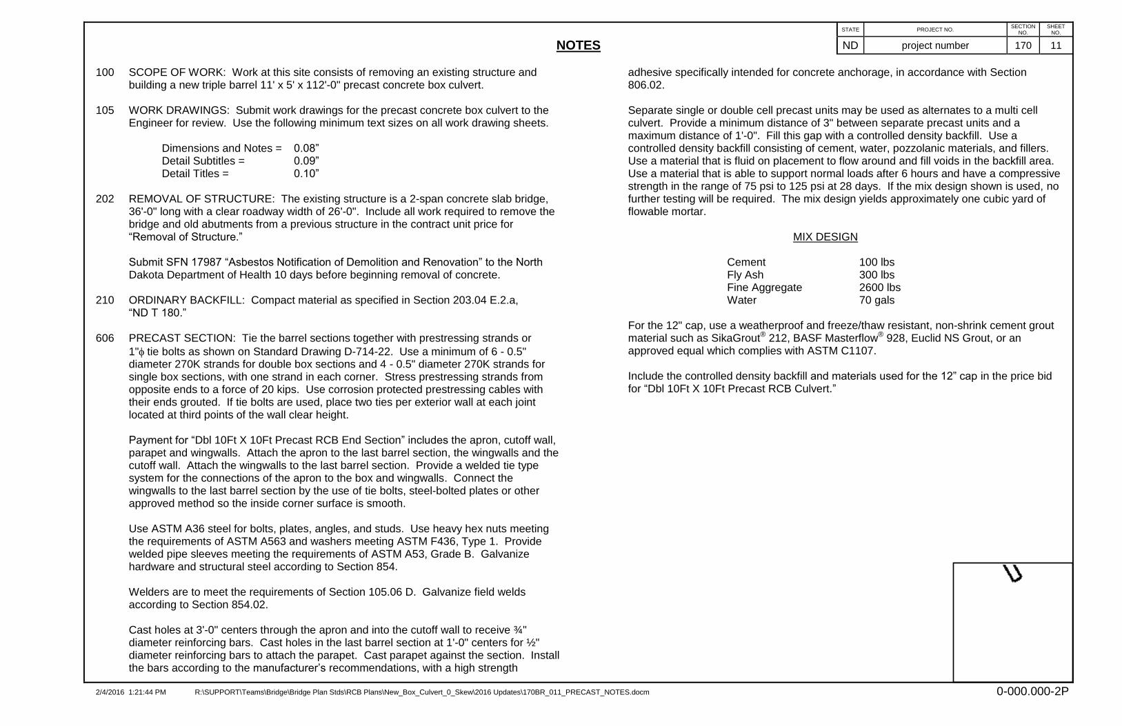
100 SCOPE OF WORK: Work at this site consists of removing an existing structure and building a new triple barrel 11' x 5' x 112'-0" precast concrete box culvert.
105 WORK DRAWINGS: Submit work drawings for the precast concrete box culvert to the
Engineer for review. Use the following minimum text sizes on all work drawing sheets. Dimensions and Notes = 0.08” Detail Subtitles = 0.09” Detail Titles = 0.10”
202 REMOVAL OF STRUCTURE: The existing structure is a 2-span concrete slab bridge,
36'-0" long with a clear roadway width of 26'-0". Include all work required to remove the bridge and old abutments from a previous structure in the contract unit price for “Removal of Structure.”
Submit SFN 17987 “Asbestos Notification of Demolition and Renovation” to the North
Dakota Department of Health 10 days before beginning removal of concrete. 210 ORDINARY BACKFILL: Compact material as specified in Section 203.04 E.2.a,
“ND T 180.” 606 PRECAST SECTION: Tie the barrel sections together with prestressing strands or
1"tie bolts as shown on Standard Drawing D-714-22. Use a minimum of 6 - 0.5" diameter 270K strands for double box sections and 4 - 0.5" diameter 270K strands for single box sections, with one strand in each corner. Stress prestressing strands from opposite ends to a force of 20 kips. Use corrosion protected prestressing cables with their ends grouted. If tie bolts are used, place two ties per exterior wall at each joint located at third points of the wall clear height.
Payment for “Dbl 10Ft X 10Ft Precast RCB End Section” includes the apron, cutoff wall,
parapet and wingwalls. Attach the apron to the last barrel section, the wingwalls and the cutoff wall. Attach the wingwalls to the last barrel section. Provide a welded tie type system for the connections of the apron to the box and wingwalls. Connect the wingwalls to the last barrel section by the use of tie bolts, steel-bolted plates or other approved method so the inside corner surface is smooth.
Use ASTM A36 steel for bolts, plates, angles, and studs. Use heavy hex nuts meeting the requirements of ASTM A563 and washers meeting ASTM F436, Type 1. Provide welded pipe sleeves meeting the requirements of ASTM A53, Grade B. Galvanize hardware and structural steel according to Section 854. Welders are to meet the requirements of Section 105.06 D. Galvanize field welds according to Section 854.02. Cast holes at 3'-0" centers through the apron and into the cutoff wall to receive ¾" diameter reinforcing bars. Cast holes in the last barrel section at 1'-0" centers for ½" diameter reinforcing bars to attach the parapet. Cast parapet against the section. Install the bars according to the manufacturer’s recommendations, with a high strength
adhesive specifically intended for concrete anchorage, in accordance with Section 806.02.
Separate single or double cell precast units may be used as alternates to a multi cell
culvert. Provide a minimum distance of 3" between separate precast units and a maximum distance of 1'-0". Fill this gap with a controlled density backfill. Use a controlled density backfill consisting of cement, water, pozzolanic materials, and fillers. Use a material that is fluid on placement to flow around and fill voids in the backfill area. Use a material that is able to support normal loads after 6 hours and have a compressive strength in the range of 75 psi to 125 psi at 28 days. If the mix design shown is used, no further testing will be required. The mix design yields approximately one cubic yard of flowable mortar.
MIX DESIGN
Cement 100 lbs Fly Ash 300 lbs Fine Aggregate 2600 lbs Water 70 gals
For the 12" cap, use a weatherproof and freeze/thaw resistant, non-shrink cement grout
material such as SikaGrout® 212, BASF Masterflow® 928, Euclid NS Grout, or an approved equal which complies with ASTM C1107.
Include the controlled density backfill and materials used for the 12” cap in the price bid for “Dbl 10Ft X 10Ft Precast RCB Culvert.”

(SHOWING SECTION ALONG ‘ ROADWAY)
1:11:1
20:120:1
HBP
(typ)
4’-0"
Sta 2331+00.0
‘ Box Culvert
(typ)
2’-0"
1’-0"
80’-0"80’-0"
(typ)
2’-6"
(typ)
7’-3"
56’-1"
(typ)
5’-0"
Fill
Foundation
Backfill
Ordinary
MULTIPLE CELL INSTALLATION
(WINGS & APRON NOT SHOWN)
Backfill
Controlled Density
A
A
1’-0"
SECTION A-A
of the number of barrels is arbitrary.
between adjacent barrels. The representation
placement of the controlled density backfill
The intent of this drawing is to show only the
Backfill
Controlled Density
1’-0" Cap
1’-0"
3" - 1’-0"
Course
Aggregate Base
Excavation
Limits of Box Culvert
41’-8" ~ Geosynthetic Geogrid Limits
THROUGH EXISTING EMBANKMENT
GEOSYNTHETIC GEOGRID PLACEMENT AND FOUNDATION FILL
NOTES:
the end of the apron.
Extend the geosynthetic material and foundation fill to
determine the depth required.
under the box with foundation fill. The Engineer will
the floor. Remove and replace all unsound material
Provide a 1’-0" minimum depth of foundation fill under
Type G
Material
Geosynthetic
STATENO.
ND
PROJECT NUMBERSHEET
NO.
SECTION
2/4/2016 dwing R:\SUPPORT\Teams\Bridge\Bridge Plan Stds\RCB Plans\New_Box_Culvert_0_Skew\2016 Updates\170BR_012_PCFILL.dgn1:35:29 PM
project number 170
XXXYYXX000
LOCATION
PRELIMINARY
purposes.
implementation
construction or
and not for
is preliminary
This drawing
EXCAVATION & FOUNDATION
FILL DETAIL
12
0-000.000-3P