image-based view morphing for teleconferencing ... · image-based view morphing for...
TRANSCRIPT

University of Otago
Information Science
supervisor: Senior Lecturer Holger Regenbrecht
25.05.2005
Image-Based View Morphing forTeleconferencing Applications
- Project Report -
Gordon Wetzstein
www.uni-weimar.de/~wetzste1

Contentpp
1 Introduction 1
2 Related Work 2
3 Background Substration 3
4 Camera Calibration 5
4.1 Intrinsic Parameters 5
4.2 Extrinsic Parameters 7
5 Rectification 8
6 Stereo Correspondence Detection 9
7 View Synthesis and Weight Estimation 10
8 References 12
9 Appendix A – Disparity Analysis in OpenCV 15
10 Appendix B – Image Morphing in OpenCV 18

1 Introduction
A teleconferencing application usually creates a consistent space, in which
all participants are more or less present. The level of presence is dependent
of many factors. One of them is whether eye-to-eye contact is possible or
not. In most cases the cameras that capture a participant are mounted
around a screen (monitor, projection screen etc.). While a participant usually
looks at the person who he/she is talking to, the cameras that capture
him/her from a different position and angle. This leads to a lack of eye-to-eye
contact that has to be overcome by creating intermediate views through view
morphing between different camera views.
The goal of an artificial view synthesis is to create consistent views for all
participants not only of the virtual conferencing room, but also of other
persons within this room. Thus each person looks at another one from the
relative position in the virtual room instead on the camera position that is
determined by the physical setup.
The components of a framework for synthesizing arbitrary views are
generally:
• a background subtraction module
• algorithms for rectifying the input images and unrectifying the generated
output image
• stereo correspondences computation
• image morphing
The following chapter gives an overview of related work, whereas chapters 3,
5, 6 and 7 describe these components in detail. Chapter 4 is about how to
calibrating the intrinsic and extrinsic camera parameters.
1
2 Related Work
Techniques that are used to generate in-between views range from those
that estimate geometry and reproject the acquired images to those that use
uncalibrated images only.
Henry Fuchs was among the first to use view morphing in a teleconferencing
application [Fuc94]. As many other approaches a disparity map is generated
by computing per pixel correspondences between rectified views of the same
scene. An accurate depth map in combination with calibrated cameras can
be used to estimate the scene geometry, reproject the video images and
render the scene from arbitrary viewpoints. Computing accurate and reliable
stereo correspondences in real-time is in this case the most challenging task.
Seitz et al [Sei96] generate arbitrary in-between views by prewarping the
source images, interpolating using computed pixel disparities and
postwarping the final image again. The pre- and postwarping is computed
using the camera's projection matrix. While Seitz shows convincing view
interpolations in his paper, these have been created by interactively selecting
about 50 corresponding features in the source images. Using it in a real-time
teleconferencing application would limit its quality to that of the computed
disparities.
Another teleconferencing system is Coliseum [Bak02], [Bak03]. It was
developed by HP and is designed for desktop setups with five FireWire
cameras that capture a person. A synthetic view is generated using MIT's
Image-Based Visual Hulls algorithm [Mat00]. This is a rather simple method
to compute the approximate geometry of the foreground objects that are
textured with the video streams.
For a more detailed overview of Image-Based Rendering (IBR) in general,
the reader is referred to [Zha04] and [Heu00]. These surveys, especially the
1st one, give an excellent overview over IBR techniques.
2
Yet another, commercially available, teleconferencing application is im.point
[http://ip.hhi.de/imedia_G3/impoint2.htm]. im.point is a result of the VIRTUE
project from the Heinrich Hertz Institute in Berlin, Germany. im.point includes
the software and hardware setup for an immersive 3D teleconferencing
system. SDKs for different modules of the software are available at
http://ip.hhi.de/imedia_G3/sdks.htm. The system uses a pyramid block
matching disparity algorithm, such as the one implemented in OpenCV, to
estimate the stereo correspondences.
3 Background Subtraction
Segmenting the video stream and subtracting the background is easy in
theory but difficult in practice. Once the background has been removed, the
person in the foreground can be seamlessly integrated in any virtual
environment such as a conference room.
Usually a snapshot of the scene without a person is required. This is the
reference frame. While continuously capturing frames from the video
camera, the reference frame is used to determine if a pixel is part of the
background or not.
Two different methods have been tested. A per pixel comparison between
the reference frame and the current video frame in RGB color space and a
comparison in HSV color space.
While in RGB all color differences (Rreference-Rcurrent, Greference-Gcurrent, Breference-
Bcurrent) are compared separately to a threshold, this is not necessary in HSV
color space. There only the H (hue) and the S (saturation) values are
compared to a threshold. V (value or intensity) is not taken into account,
which should make this approach somewhat more lighting independent.
Unfortunately both approaches do not work very well in practice due to
changing lighting situations in real world environments. Common light
3

sources such as fluorescent tubes lead to flickering artifacts in the video
stream that are hardly noticeable from a human observe. These slight
changes in the captured image make it difficult to correctly subtract the
background from the person. This problem occurs also when working in HSV
space, subtraction in HSV color space works even worse than subtraction in
RGB space.
Figure 1: view from two different perspectives
Figure 2: The background is subtracted in RGB space
Figure 3: The background is subtracted in HSV space
4
The camera's exposure time, white balance and intensity have to be fixed
and should not change at all.
4 Camera Calibration
While some of the view synthesis approaches do not require calibrated
cameras, some do. Thus calibration techniques for estimating the intrinsic
and extrinsic camera parameters are discussed briefly.
4.1 Intrinsic Parameters
Intrinsic camera parameters include:
• focal length (fc),
• principal point (cc),
• skew coefficient (alpha) and
• distortion coefficients for radial and tangential distortion (kc)
An easy and accurate method for determining the camera's intrinsic
parameters is to use OpenCV's CalibFilter. OpenCV
[http://sourceforge.net/projects/opencvlibrary/] is an open source image
processing library.
Using the DirectX tool GraphEdit you can insert the calbfilter into a
DirectShow filter graph and compute the parameters using a checkerboard
patters. The intrinsic parameters can be stored in a file and loaded in any
application. OpenCV's undistortion functions can easily generate undistorted
camera views.
The filter and GraphEdit are included in the /tools folder.
5

Figure 4: Calibrating cameras with OpenCV's StereoDemo
Figure 5: Calibrating cameras with a modified version of OpenCV's CalibFilter
6
4.2 Extrinsic Parameters
The extrinsic camera parameters are the camera's translation and rotation
with respect to some fixed coordinate origin in space. These parameters are
usually stored in a 4x4 or 4x3 matrix.
OpenCV can be used to estimate the extrinsic camera parameters, too. The
same planar checkerboard pattern can be used and an extended version of
the CalibFilter with source code is included in the /tools folder. This filter can
be used to not only estimate the intrinsic parameters but also the extrinsic
ones and save them to different files.
Another tool that can serve for camera calibration and test OpenCV stereo
correspondence functionality is called StereoDemo. A compiled version is
included in the /tools folder. StereoDemo can capture two synchronized
camera streams, save them to avi files, calibrate the cameras and show the
stereo correspondence function of OpenCV.
Unfortunately it has rectifying the images in the StereoDemo has never
worked. Even though the cameras were calibrated the rectified images just
remained black. The estimated extrinsic parameters did not seem to fit the
physical scene. The distance in x has been estimated with about 16 cm
difference while it is actually about 35 cm. Since there is sort of no
documentation at all it is hard to guess what exactly could be wrong, but
obviously the extimated camera parameters are not correct. Using the
incorrect parameters to rectify the images could lead to nonsens, which
would explain the black images.
7

5 Rectification
Almost every stereo correspondence algorithm requires rectified camera
images. Rectified images are distorted in a way, that they simulate parallel
cameras. In such a setup corresponding pixel are on the same horizontal
epipolar line.
The images can be either rectified using the fundamental matrix or the
extrinsic and intrinsic camera parameters.
The fundamental matrix is the algebraic representation of the epipolar
geometry. It can be computed with a sparse set of known corresponding
features in two different views. OpenCV offer functions to compute the
fundamental matrix out of at least 8 (manually selected) corresponding
features. Using cvFindFundamentalMat() the fundamental matrix can easily be
computed. This matrix is independent of the video content and has to be
computed only once, if the cameras stay on the same position. Appendix B
includes code fragments how to compute the fundamental matrix and use it
to morph between two images.
The latest CVS version of OpenCV has build-in functions for rectifying
images using the intrinsic and extrinsic camera parameters. These are not
documented and only used in the StereoDemo application. It appears that a
look-up table in form of an image is generated using the camera's intrinsic
parameters to distort the original image on a per-pixel basis. For detailed
information consult the OpenCV mailing list
[http://groups.yahoo.com/group/OpenCV/] or the StereoDemo source code.
8
6 Stereo Correspondence Detection
Much research has been done in correct stereo correspondence detection.
An overview and comparison of the most important techniques can be found
in [Scha02]. The same group (Scharstein and Szeliski, Microsoft Research)
has source code with the implementation of these algorithms on their
website (www.middlebury.edu/stereo). The code is included in /
tools/StereoCorrespondences/StereoMatch.
Another recommended introduction into calibrated and uncalibrated stereo
vision is http://www.cs.wisc.edu/~chaol/cs766/cs766.html.
Yet another website that has excellent links to many research projects and
code resources in this area is
http://www-2.cs.cmu.edu/afs/cs/project/cil/ftp/html/v-source.html.
A general statement from Marc Levoy in his LightField paper [Lev96] is:
'Automatically finding correspondences between pairs of images is the
classic problem of stereo vision, and unfortunately although many algorithms
exist, these algorithms are fairly fragile and may not always find the correct
correspondences.'
Basically there are two different approaches: either a per-pixel disparity map
that encodes the relation for each pixel of a reference image to pixels in
another image is computed or single features (point or line features) are
computed in both images and cross-dissolved.
Standard optical flow feature tracking methods can be used to determine a
correlation between several images over time and for images acquired at the
same time from multiple cameras.
Functions for all these methods are implemented in OpenCV.
Implementation details for both methods using OpenCV are discussed in
Appendix A.
9
7 View Synthesis and Weight Estimation
A synthetic view from an arbitrary camera position is usually created by
interpolating stereo features on a per-pixel basis. Thus a dense disparity
map is required, which is either computed directly by the stereo
correspondence algorithm or interpolated using corresponding point
features.
In case of given corresponding point features the remaining pixels have to be
interpolated. This can e. g. Be done in real-time on programmable graphics
hardware. The features are triangulated and rendered as triangles, textured
with the videostream images. The vertices of this mesh can be deformed
toward their corresponding position in the other image according to weights.
The textures have to be blended respectively. This method has been
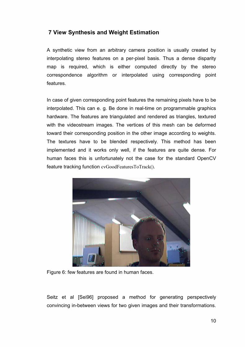
implemented and it works only well, if the features are quite dense. For
human faces this is unfortunately not the case for the standard OpenCV
feature tracking function cvGoodFeaturesToTrack().
Figure 6: few features are found in human faces.
Seitz et al [Sei96] proposed a method for generating perspectively
convincing in-between views for two given images and their transformations.
10

The method is a three step algorithm that works as follows:
1. prewarp the (rectified) images with the camera's projection matrices
2. dynamically find correspondences between images and create morph
3. postwarp resulting image
Seitz method has convincing results, however, the corresponding features
for all the images in the paper have been selected manually. The problem of
finding correct pixel correspondances remains.
OpenCV again offers functionality for creating morphs between two images.
A detailed description can be found in Appendix B. Unfortunately this method
is restricted to two input images and resulting images often contain artifacts.
In order to use any view synthesis a weight has to be assigned to each
source camera according to the position of the remote viewer with respect to
the virtual position of the other participant on the screen. Using these weights
colors and 2D positions of each pixel in the synthesized view are dynamically
interpolated.
The weights for each source camera can easily be computed using
customized weighting equations such as proposed in [Bue01] and [Bim05].
The computation of these weights is straightforward using the videoplane
metaphor as proposed in [Reg04].
We assuming that two persons participate in a teleconferencing application.
The method is independent of the number of participants. Person one sees
person two on his 2 dimensional screen as a flying plane textured with
person two's camera stream. The center of the videoplane's bounding box
on one's screen is (vpx, vpy). Person two's real camera setup is assumed to
be located around his screen on known 2D screen coordinates Ci. A penalty
in for of the euclidean distance can be determined for each source camera
based on vp and Ci i=vp x−cix2vp y−ciy2
. The weight for each source
camera can be computed from the penalties .
11

These weights have to be normalized by
This method is independent of the amount of source cameras and
guarantees, that if the viewpoint is the same as the camera position, the
weight of this camera is equal one.
Unfortunately this has never been implemented, because the quality of the
computed stereo correspondences even for two cameras has never been
good enough.
8 References
[Bak02] Baker, H.H.; Tanguay, D.; Sobel, I.; Gelb, D.; Goss, M.E.;
Culbertson, W.B.; Malzbender, T. „The Coliseum Immersive
Teleconferencing System“. HP Technical Report HPL-2002-
351, 2002
[Bak03] Baker, H.H.; Bhatti, N., Tanguay, D.; Sobel, I.; Gelb, D.; Goss,
M.E.; MacCormick, J., Yusa, K. Culbertson, W.; Malzbender, T.
„The Coliseum Immersive Teleconferencing System“. HP
Technical Report HPL-2003-129, 2003
[Bim05] Bimber, O., Wetzstein, G., Emmerling, A. and Nitschke, C.
„Enabling View-Dependent Stereoscopic Projects in Real
Environments“. To appear in Proceedings of ISMAR 2005
12
11max{ }
ii
i i
dw
d dæ ö
= - ×ç ÷è ø
{ }i
ii
ww
w=S

[Bir98] Birchfield, S. and Tomasi, C. “Depth Discontinuities by Pixel-to-
Pixel Stereo”. In Proc of International Conference on Compuer
Vision, 1998
[Bue01] Chris Buehler, Michael Bosse, Leonard McMillan, Steven
Gortler and Michael Cohen. „Unstructured lumigraph rendering„
In Proceedings of Siggraph 2001
[Cri03] Criminisi, A., Shotton, J., Blake, A., Rother, C., Torr, P.H.S.
“Efficient Dense-Stereo and Novel-view Synthesis for Gaze
Manipulation in One-to-one Teleconferencing”. TR MSR-TR-
2003-59, Microsoft Research, 2003
[Fuc94] Fuchs, Henry, Gary Bishop, Kevin Arthur, Leonard McMillan,
Ruzena Bajcsy, Sang Lee, Hany Farid, and Takeo Kanade,
"Virtual Space Teleconferencing Using a Sea of Cameras,"
Proceedings of the First International Symposium on Medical
Robotics and Computer-Assisted Surgery, vol. 2, pp. 161-167,
September 22-24, 1994, Pittsburgh, PA.
[Heu00] Heung-Yeung Shum and Sing Bing Kang. "A Review of Image-
based Rendering Techniques", IEEE/SPIE Visual
Communications and Image Processing (VCIP) 2000, pp. 2-13,
Perth, June 2000
[Lev96] Levoy, Mark and Hanrahan, Pat. „Light Field Rendering“. In
Proceedings of ACM Siggraph 1996
[Mat00] Matusik, W., Buehler, C., Raskar, R., Gortler, S., McMillan, L.
“Image-Based Visual Hulls”. In Proc of Siggraph 2000
[Pil97] Pilu, M. “Uncalibrated Stereo Correspondence by Singular
Value Decomposition”. TR HPL-97-96, HP Bristol, 1997
13

[Reg04] Regenbrecht, H., Lum, T. Kohler, P., Ott, C., Wagner, M.,
Wilke, W. And Mueller, E. „Using Augmented Virtuality for
Remote Collaboration“. Presence 2004
[Scha02] Scharstein and R. Szeliski. A Taxonomy and Evaluation of
Dense Two-Frame Stereo Correspondence Algorithms.
IJCV 47(1/2/3):7-42, April-June 2002
[Schr01] O. Schreer, N. Brandenburg, P. Kauff, Real-Time Disparity
Analysis for Applications in Immersive Tele-Conference
Scenarios - A Comparative Study", Proc. of ICIAP 2001, 11th
Int. Conf. on Image Analysis and Processing, Palermo, Italy,
September 2001
[Sei96] SEITZ, S. and DYER, C. 1996. View Morphing. In Proceedings
of ACM SIGGRAPH 96, 21-30.
[Zha04] C. Zhang and T. Chen, "A Survey on Image-Based Rendering -
Representation, Sampling and Compression", EURASIP Signal
Processing: Image Communication, pp. 1-28, Vol. 19, No. 1,
Jan. 2004 (invited paper).
14
9 Appendix A – Disparity Analysis in OpenCV
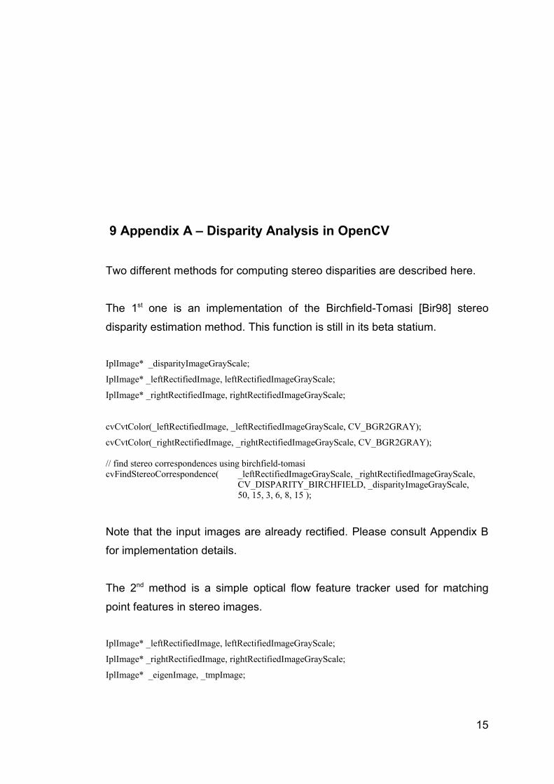
Two different methods for computing stereo disparities are described here.
The 1st one is an implementation of the Birchfield-Tomasi [Bir98] stereo
disparity estimation method. This function is still in its beta statium.
IplImage* _disparityImageGrayScale;
IplImage* _leftRectifiedImage, leftRectifiedImageGrayScale;
IplImage* _rightRectifiedImage, rightRectifiedImageGrayScale;
cvCvtColor(_leftRectifiedImage, _leftRectifiedImageGrayScale, CV_BGR2GRAY);
cvCvtColor(_rightRectifiedImage, _rightRectifiedImageGrayScale, CV_BGR2GRAY);
// find stereo correspondences using birchfield-tomasicvFindStereoCorrespondence( _leftRectifiedImageGrayScale, _rightRectifiedImageGrayScale,
CV_DISPARITY_BIRCHFIELD, _disparityImageGrayScale, 50, 15, 3, 6, 8, 15 );
Note that the input images are already rectified. Please consult Appendix B
for implementation details.
The 2nd method is a simple optical flow feature tracker used for matching
point features in stereo images.
IplImage* _leftRectifiedImage, leftRectifiedImageGrayScale;
IplImage* _rightRectifiedImage, rightRectifiedImageGrayScale;
IplImage* _eigenImage, _tmpImage;
15
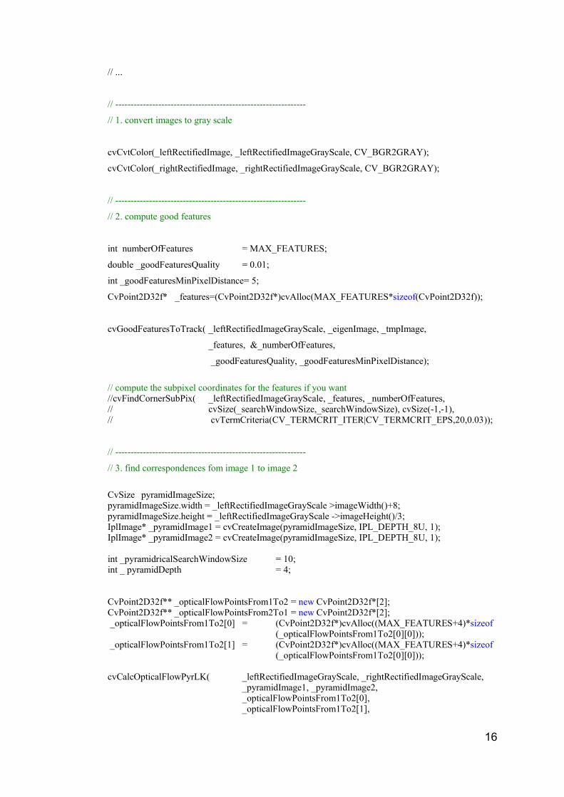
// ...
// --------------------------------------------------------------
// 1. convert images to gray scale
cvCvtColor(_leftRectifiedImage, _leftRectifiedImageGrayScale, CV_BGR2GRAY);
cvCvtColor(_rightRectifiedImage, _rightRectifiedImageGrayScale, CV_BGR2GRAY);
// --------------------------------------------------------------
// 2. compute good features
int numberOfFeatures = MAX_FEATURES;
double _goodFeaturesQuality = 0.01;
int _goodFeaturesMinPixelDistance= 5;
CvPoint2D32f* _features=(CvPoint2D32f*)cvAlloc(MAX_FEATURES*sizeof(CvPoint2D32f));
cvGoodFeaturesToTrack( _leftRectifiedImageGrayScale, _eigenImage, _tmpImage,
_features, &_numberOfFeatures,
_goodFeaturesQuality, _goodFeaturesMinPixelDistance);
// compute the subpixel coordinates for the features if you want//cvFindCornerSubPix( _leftRectifiedImageGrayScale, _features, _numberOfFeatures, // cvSize(_searchWindowSize,_searchWindowSize), cvSize(-1,-1),// cvTermCriteria(CV_TERMCRIT_ITER|CV_TERMCRIT_EPS,20,0.03));
// --------------------------------------------------------------
// 3. find correspondences fom image 1 to image 2
CvSize pyramidImageSize;pyramidImageSize.width = _leftRectifiedImageGrayScale >imageWidth()+8;pyramidImageSize.height = _leftRectifiedImageGrayScale ->imageHeight()/3;IplImage* _pyramidImage1 = cvCreateImage(pyramidImageSize, IPL_DEPTH_8U, 1);IplImage* _pyramidImage2 = cvCreateImage(pyramidImageSize, IPL_DEPTH_8U, 1);
int _pyramidricalSearchWindowSize = 10;int _ pyramidDepth = 4;
CvPoint2D32f** _opticalFlowPointsFrom1To2 = new CvPoint2D32f*[2];CvPoint2D32f** _opticalFlowPointsFrom2To1 = new CvPoint2D32f*[2]; _opticalFlowPointsFrom1To2[0] = (CvPoint2D32f*)cvAlloc((MAX_FEATURES+4)*sizeof
(_opticalFlowPointsFrom1To2[0][0])); _opticalFlowPointsFrom1To2[1] = (CvPoint2D32f*)cvAlloc((MAX_FEATURES+4)*sizeof
(_opticalFlowPointsFrom1To2[0][0]));
cvCalcOpticalFlowPyrLK( _leftRectifiedImageGrayScale, _rightRectifiedImageGrayScale, _pyramidImage1, _pyramidImage2,_opticalFlowPointsFrom1To2[0], _opticalFlowPointsFrom1To2[1],
16
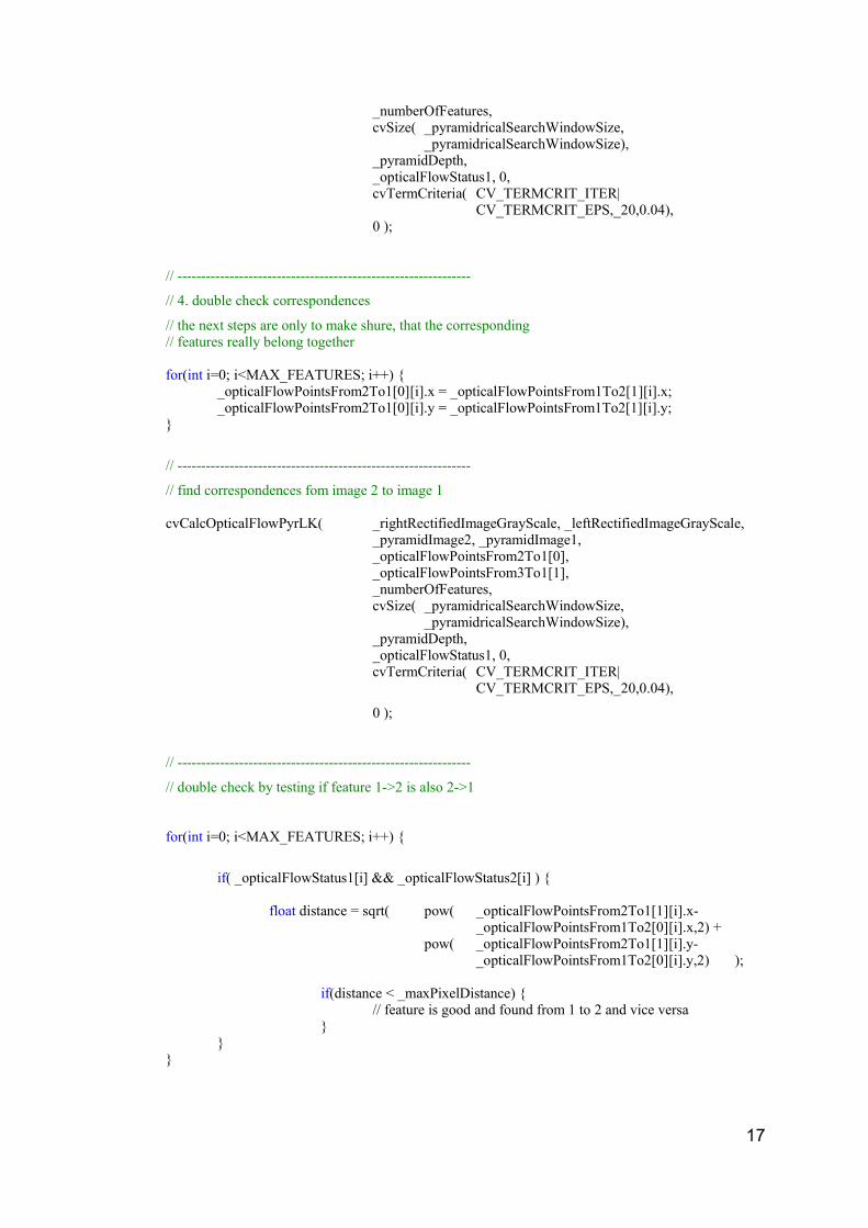
_numberOfFeatures, cvSize( _pyramidricalSearchWindowSize,
_pyramidricalSearchWindowSize), _pyramidDepth, _opticalFlowStatus1, 0,cvTermCriteria( CV_TERMCRIT_ITER|
CV_TERMCRIT_EPS,_20,0.04), 0 );
// --------------------------------------------------------------
// 4. double check correspondences
// the next steps are only to make shure, that the corresponding// features really belong together
for(int i=0; i<MAX_FEATURES; i++) {_opticalFlowPointsFrom2To1[0][i].x = _opticalFlowPointsFrom1To2[1][i].x;_opticalFlowPointsFrom2To1[0][i].y = _opticalFlowPointsFrom1To2[1][i].y;
}
// --------------------------------------------------------------
// find correspondences fom image 2 to image 1
cvCalcOpticalFlowPyrLK( _rightRectifiedImageGrayScale, _leftRectifiedImageGrayScale, _pyramidImage2, _pyramidImage1,_opticalFlowPointsFrom2To1[0], _opticalFlowPointsFrom3To1[1], _numberOfFeatures, cvSize( _pyramidricalSearchWindowSize,
_pyramidricalSearchWindowSize), _pyramidDepth, _opticalFlowStatus1, 0,cvTermCriteria( CV_TERMCRIT_ITER|
CV_TERMCRIT_EPS,_20,0.04),
0 );
// --------------------------------------------------------------
// double check by testing if feature 1->2 is also 2->1
for(int i=0; i<MAX_FEATURES; i++) {
if( _opticalFlowStatus1[i] && _opticalFlowStatus2[i] ) {
float distance = sqrt( pow( _opticalFlowPointsFrom2To1[1][i].x-_opticalFlowPointsFrom1To2[0][i].x,2) +
pow( _opticalFlowPointsFrom2To1[1][i].y-_opticalFlowPointsFrom1To2[0][i].y,2) );
if(distance < _maxPixelDistance) {// feature is good and found from 1 to 2 and vice versa
}}
}
17

10 Appendix B – Image Morphing in OpenCV
First of all we need at least eight corresponding features that can be selected
interactively. These are required to compute the fundamental matrix. This
has to be done only once.
IplImage* morphedImage, leftImage, rightImage;
// --------------------------------------------------------------
// 1. compute fundamental matrix
CvMat * _fundamentalMatrix, points1, point2, status;
// fill point coordinates to points1 and points2
int res = cvFindFundamentalMat( points1, points2, _fundamentalMatrix,
CV_FM_RANSAC, 1.0, 0.99, status );
// matrix has not been found
if(!res) { /* do something */ }
// --------------------------------------------------------------
// 2. compute corresponding epilines
CvMat* epilines1 = cvCreateMat(3,numCorrespondingFeatures,CV_32F);CvMat* epilines2 = cvCreateMat(3,numCorrespondingFeatures,CV_32F);
cvComputeCorrespondEpilines( points1, 1, _fundamentalMatrix, epilines1);cvComputeCorrespondEpilines( points2, 2, _fundamentalMatrix, epilines2);
// --------------------------------------------------------------
// 3. compute number and length of the epilines
18

int _ lineCount;
cvMakeScanlines( &_fundamentalMatrix, cvSize(imageWidth, imageHeight),0, 0, 0, 0, &_lineCount );
int _lengthEpilines1 = new int[_lineCount];int _lengthEpilines2 = new int[_lineCount];
int _epilinesInt1 = new int[4*_lineCount];int _epilinesInt2 = new int[4*_lineCount];
cvMakeScanlines( &_fundamentalMatrix, cvSize(imageWidth, imageHeight),_epilinesInt1, _epilinesInt2, _lengthEpilines1, _lengthEpilines2, &_lineCount );
// --------------------------------------------------------------// 4. prewarp the source images
uchar _preWarpData1 = new uchar[max(imageWidth,imageHeight)*_lineCount*3];uchar _preWarpData2 = new uchar[max(imageWidth,imageHeight)*_lineCount*3];
cvPreWarpImage( _lineCount, leftImage, _preWarpData1, _lengthEpilines1, _epilinesInt1 );cvPreWarpImage( _lineCount, rightImage, _preWarpData2, _lengthEpilines2, _epilinesInt2 );
// --------------------------------------------------------------// 5. find runs for the rectified image [series of pixels // with similar intensity]
int _numRuns1 = new int[_lineCount];int _numRuns2 = new int[_lineCount];
int _runs1 = new int[leftImage->imageWidth()*_lineCount];int _runs2 = new int[leftImage->imageWidth()*_lineCount];
int _runCorrelation1 = new int[max(imageWidth,imageHeight)*_lineCount*3];int _runCorrelation2 = new int[max(imageWidth,imageHeight)*_lineCount*3];
cvFindRuns( _lineCount, _preWarpData1, _preWarpData2,_lengthEpilines1, _lengthEpilines2,_runs1, _runs2, _numRuns1, _numRuns2 );
// --------------------------------------------------------------// 6. find correspondences between runs
int *scanlinesMorphedImage = new int[_lineCount*2*4]; int *numScanlinesMorphedImage = new int[_lineCount*2*4];
cvDynamicCorrespondMulti( _lineCount, _runs1, _numRuns1,_runs2, _numRuns2, _runCorrelation1, _runCorrelation2);
// --------------------------------------------------------------// 7. morph the images!
uchar *tmpDataImageDst = new uchar[max(imageWidth,imageHeight)*_lineCount*3];
// weight for the two source imagesfloat alpha = 0.5;
cvMorphEpilinesMulti( _lineCount,_preWarpData1, _lengthEpilines1,_preWarpData2, _lengthEpilines2, tmpDataImageDst,
19

numScanlinesMorphedImage, alpha, _runs1, _numRuns1, _runs2, _numRuns2, _runCorrelation1, _runCorrelation2 );
// --------------------------------------------------------------// 8. post warp the image
cvPostWarpImage( _lineCount, tmpDataImageDst, numScanlinesMorphedImage,_morphedImage, scanlinesMorphedImage );
// --------------------------------------------------------------// 9. delete moiree effect from warped image
cvDeleteMoire( _morphedImage );
20