image formation - geometryyfwang/courses/cs281b/notes/9-projection-geometry.pdfcamera geometry...
TRANSCRIPT

Image Formation - Geometry

Geometry Aspect
Where does the image of a point end up with?
Geometry transform
A unique mapping
Lens effect
Both geometrical and color distortion
Not necessarily a unique mapping

Camera geometry
Projection models
Where are points in the world imaged? That is, where do they
show up in the image?
The point P = (x, y, z) shows up at P' = (x', y')
What is the relationship between P and P' ?
P' = fproj(P)
What is fproj? Is it linear, nonlinear…?
Different projection models determine different fproj’s
Why is there more than one? Is one “right”?
What does a real camera do?

Pinhole camera model
A pinhole camera is a good approximation of the geometry
of the imaging process
A true pinhole camera is a mathematical abstraction
An inverted image is created on the image place in the
“pinhole perspective projection model”
Every visible point in the scene can be traced via a straight line
through the pinhole to the image plane

Perspective projection
In such a perspective projection:
The image is inverted
Can instead consider an upright virtual image
Distant objects appear smaller in the image than near objects
Points project to points
Lines project to lines
What do circles project to?
What do parallel lines project to?
What do squares project to?
What do polyhedra project to?

Polyhedra
Polygons

Perspective and art
Use of correct perspective projection indicated in 1st
century B.C. frescoes
Skill resurfaces in Renaissance: artists develop
systematic methods to determine perspective
projection (around 1480-1515)
Durer, 1525Raphael

Important parameters
The origin of the camera coordinate system (O)
The center of projection
“Inside the lens”
The optical axis
Perpendicular to the lens
Z axis
The focal distance ( f )
For now, this is the distance of the image plane Π' (along z)
The image plane (Π')
Real or virtual
The image center (C‘)
Where the optical axis intersects the image plane

Pinhole perspective projection
model
Center of projection:
Origin of camera
coordinate system
spanned by right-
handed coordinate
system – basis
vectors (i, j, k)
Image plane
Optical axis
Image center
Scene point
Image point
fzz
yfy
z
xfx

Pinhole perspective projection
model
Center of projection:
Origin of camera
coordinate system
spanned by right-
handed coordinate
system – basis
vectors (i, j, k)
Image plane
Optical axis
Image center
Scene point
Image point
fzz
yfy
z
xfx
u
v

Perspective Projection Matrix
divide by the third
coordinate to convert back
to non-homogeneous
coordinates
• Projection is a matrix multiplication using homogeneous
coordinates:
fz
y
x
z
y
x
f /1
0'/100
0010
0001
),(z
yf
z
xf
Complete mapping from world points to image pixel
positions?

Projection geometry
Image planePinholeScene objects
Will the same object twice as far away look half the size?

Projection geometry
2d
yy
h2 h1
O
d
f
2 So
2 and
21
21
hh
f
h
d
y
f
h
d
y

Virtual image plane
Projection inverts the image, which can make the math
inconvenient and the intuition difficult
It’s easier to think of the upright scene producing an upright
image!
So, we’ll often use the virtual image plane rather than the
true image plane
The geometry is essentially the same, with sign reversals
Caveat: When dealing with lens details and focusing, we’ll
have to first deal with the true image plane

(x’, y’, z’)
(0,0,0)
(x , y , z )
Virtual image plane
True image planef
f

Perspective projection & calibration
Perspective equations so far in terms of camera’s
reference frame….
Camera’s intrinsic and extrinsic parameters needed to
calibrate geometry.
Camera frame

Perspective projection & calibration
Camera frame
Intrinsic:
Image coordinates relative to
camera Pixel coordinates
Extrinsic:
Camera frame World frame
World
frame
World to
camera coord.
trans. matrix
(4x4)
Perspective
projection matrix
(3x4)
Camera to
pixel coord.
trans. matrix
(3x3)
=2D
point
(3x1)
3D
point
(4x1)

Intrinsic parameters
5 intrinsic parameters account for
The focal length ( f )
The principal point (C0)=(u0,v0)
Where the optical axis intersects the image plane
Pixel aspect ratio (ku, kv)
Pixels aren’t necessarily square
Angle between the axes (θ)
Skewness in manufacturing
θ

Intrinsic parameters
realx
idealx
idealy xcamera
ycamera
z
1/kv
1/ku
Principal point
C0 = (u0, v0)
f
θ
Orealy
Sensor array – real image plane
Normalized (ideal) image plane

Intrinsic parameters: from idealized
world coordinates to pixel values
z
yfv
z
xfu
Perspective projection
W. Freeman
fz
y
x
z
y
x
f /1
0'/100
0010
0001

Intrinsic parameters
z
yv
z
xu
But “pixels” are in some
arbitrary spatial units
W. Freeman

Intrinsic parameters
z
yv
z
xu
Maybe pixels are not
square
W. Freeman

Intrinsic parameters
0
0
vz
yv
uz
xu
We don’t know the origin
of our camera pixel
coordinates
W. Freeman

Intrinsic parameters
0
0
)sin(
)cot(
vz
yv
uz
y
z
xu
May be skew between
camera pixel axes
v
u
v
u
vuvuu
vv
)cot()cos(
)sin(
W. Freeman

pp C K
Intrinsic parameters, homogeneous coordinates
0
0
)sin(
)cot(
vz
yv
uz
y
z
xu
u
v
1
cot() u0
0
sin()v0
0 0 1
0
0
0
x
y
z
1
Using homogenous coordinates,
we can write this as:
or:
In camera-based coords
In pixels

Extrinsic parameters: translation
and rotation of camera frame
tpRp C
W
WC
W
C
Non-homogeneous
coordinates
Homogeneous
coordinates
ptRp WC
W
C
W
C
1000
|
|

Combining extrinsic and intrinsic
calibration parameters, in homogeneous
coordinates
ptRKp WC
W
C
W
pp CK
pMp W
Intrinsic
Extrinsic
ptRp WC
W
C
W
C
1000
|
|
World coordinates
Camera coordinates
pixels
0 0 0 1

Homography
Two special cases:
Object is a single plane
The camera execute a simple rotation
Proof, based on projection equation, that image coordinates
in multiple frames are related by homography

Other ways to write the same equation
1...
...
...
1 3
2
1
z
W
y
W
x
W
T
T
T
p
p
p
m
m
m
v
u
pMp W
Pm
Pmv
Pm
Pmu
3
2
3
1
pixel coordinates
world coordinates
Conversion back from homogeneous
coordinates leads to:
W. Freeman

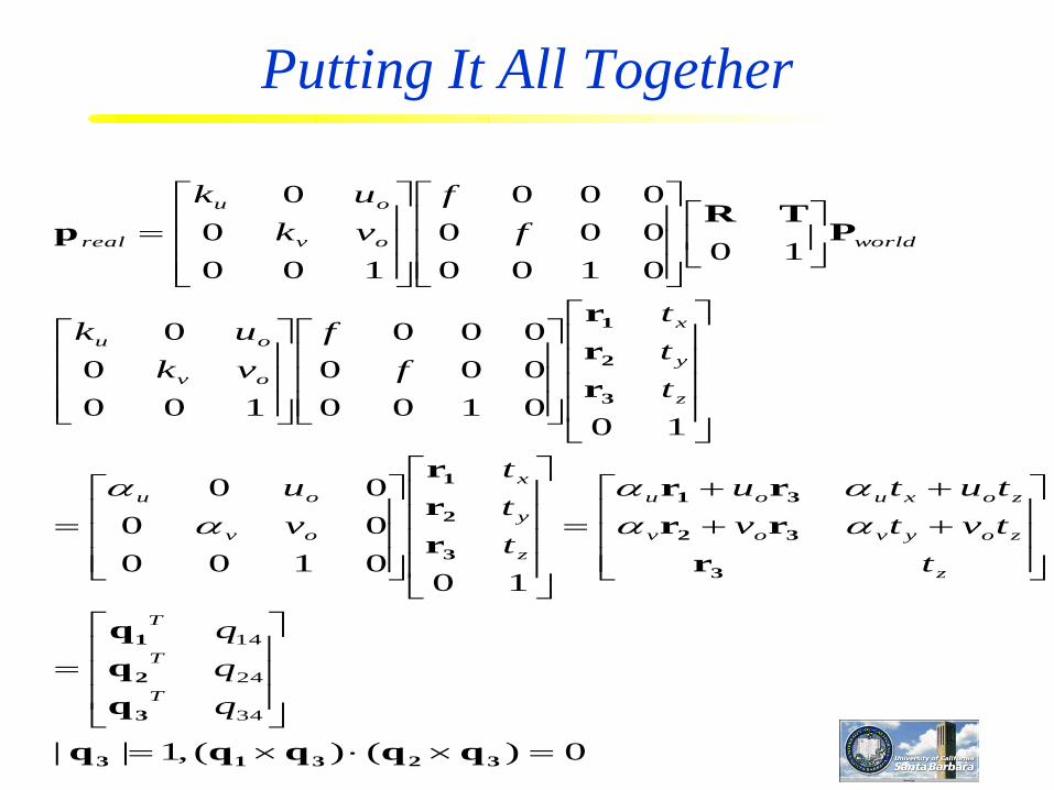
Putting It All Together
34333231
24232221
34333231
14131211
34333231
24232221
14131211
qZqYqXq
qZqYqXqy
qZqYqXq
qZqYqXqx
qqqq
qqqq
qqqq
worldworldworld
worldworldworldreal
worldworldworld
worldworldworldreal
worldworldworldreal
worldworldcameracameraidealidealrealreal
PPM
PMMMp

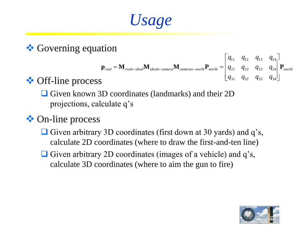
Usage
Governing equation
Off-line process
Given known 3D coordinates (landmarks) and their 2D
projections, calculate q’s
On-line process
Given arbitrary 3D coordinates (first down at 30 yards) and q’s,
calculate 2D coordinates (where to draw the first-and-ten line)
Given arbitrary 2D coordinates (images of a vehicle) and q’s,
calculate 3D coordinates (where to aim the gun to fire)
worldworldworldcameracameraidealidealrealreal
qqqq
qqqq
qqqq
PPMMMp
34333231
24232221
14131211

Camera Calibration and Registration
First step
Estimate the combined transformation matrix
Second step
Estimate intrinsic camera parameters
Estimate extrinsic camera parameters
Solution
Using objects of known sizes and shapes (6 points at least)
Each point provides two constraints (x,y)
A checked board pattern placed at different depths
worldrealM
0)()(,1||
100100
00
00
100100
000
000
100
0
0
100100
000
000
100
0
0
34
24
14
32313
3
2
1
3
32
31
3
2
1
3
2
1
qqqqq
q
q
q
r
rr
rr
r
r
r
r
r
r
PTR
p
q
q
q
t
tvtv
tutu
t
t
t
v
u
t
t
t
f
f
vk
uk
f
f
vk
uk
T
T
T
z
zoyvov
zoxuou
z
y
x
ov
ou
z
y
x
ov
ou
worldov
ou
real
Putting It All Together
Camera Calibration
Certainly, not all 3x4 matrices are like above
3x4 matrices have 11 free parameters (with a scale factor that
cannot be decided uniquely)
matrix in the previous slide has 10 parameters (2 scale, 2 camera
center, 3 translation, 3 rotation)
additional constraints can be very useful
to solve for the matrix, and
to compute the parameters
Theorem: 3x4 matrices can be put in the form of the previous slide
if and only if the following two constraints are satisfied
0)()(,1|| 32313 qqqqq

Finding the transform matrix
0AQ
PqPqPq
Pq
PqPqPq
Pq
P
q
q
q
q
q
q
P
q
q
q
p
32
3
2
31
3
1
3
2
1
3
2
1
3
2
1
0
0
1
1
3424
33
34
3
24
3
3414
33
34
3
14
3
3
34
24
14
34
24
14
34
24
14
vqqvyq
q
uqquxq
q
q
q
q
Z
Y
X
q
q
q
w
wy
wx
q
q
q
world
T
world
T
real
world
T
world
T
world
T
world
T
real
world
T
world
T
world
T
T
T
world
world
world
T
T
T
real
real
world
T
T
T
real

Each data point provide two equations, with at least 6
points we will have 12 equations for solving 11
numbers up to a scale factor
Lagrange multipliers can be used to incorporate other
constraints
The usual constraint is q32=1
Afterward, both intrinsic and extrinsic parameters can
be recovered
Finding the transform matrix (cont.)

Details
Solved by Langrage multiplier
)||1(min
1|| subject tomin
2
3
2
3
2
qAQ
qAQ
0AQ
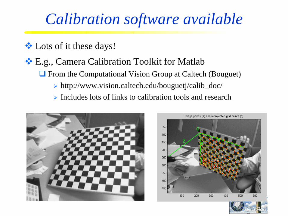
Calibration software available
Lots of it these days!
E.g., Camera Calibration Toolkit for Matlab
From the Computational Vision Group at Caltech (Bouguet)
http://www.vision.caltech.edu/bouguetj/calib_doc/
Includes lots of links to calibration tools and research

Flexible Pattern Placement
http://research.microsoft.com/~zhang/calib/

Step 1: Intrinsic Parameters
ximage=Hxplane=K[R1,R2,T]xplane
2
1
21
1
12
1
1
1
1
1
1
1
1
1
1
2
1
1
1
213
1
2
1
1
1
21321
21
0
)()(0)(
][
][
][
hKKhhKKhhKKh
hKhKhKhKhKhK
TRRhKhKhK
TRRKhhh
TRRKH
TTTTTT
TTT
One homography
8 DOFs
6 extrinsic parameters (3 rotation + 3 translation)
2 constraints on intrinsic parameters
3 planes in general configuration
Image of absolute conic

Step 2: Extrinsic Parameters
2
1
1
1
213
3
1
2
1
2
1
1
1
21321
21
11
][
][
hKhK
RRR
hKT
hKR
hKR
TRRKhhh
TRRKH

Step 3: Intrinsic + Extrinsic Parameters
ximage=Hxplane=K[R1,R2,T]xplane
2model
21
1 1
)][( ij
n
i
m
j
ij xTRRKximage
Nonlinear optimization
Using Lenvenberg-Marquardt in Minpack
K from the previous step as initial guess
# of images # of points/images
Usage
Governing equation
Off-line process
Given known 3D coordinates (landmarks) and their 2D
projections, calculate q’s
On-line process
Given arbitrary 3D coordinates (first down at 30 yards) and q’s,
calculate 2D coordinates (where to draw the first-and-ten line)
Given arbitrary 2D coordinates (images of a vehicle) and q’s,
calculate 3D coordinates (where to aim the gun to fire)
worldworldworldcameracameraidealidealrealreal
qqqq
qqqq
qqqq
PPMMMp
34333231
24232221
14131211

Pan encoder
Tilt encoder
Remote
Sensor

Coordinate systems
World
Camera

Coordinate systems
W
C
world
camera
ideal image
real image

Example

Vanishing points, horizon lines
Parallel lines in the scene intersect at the horizon line
Each pair of parallel lines meet at a vanishing point
The collection of vanishing points for all sets of parallel lines in a
given plane is collinear, called the horizon line for that plane

Perspective effects

Example

Vanishing points, horizon lines

Parallel lines
Virtual image plane
Scene objects Pinhole
Where does the horizon line appear in the image?

Affine projection models
Perspective projection is an ideal abstraction, an
approximation of the true imaging geometry
There are other projection models too!
Affine projection models are simpler, though less
accurate:
Orthographic projection
Parallel projection
Weak-perspective projection
Paraperspective projection
No matter which model you use, the equations are linear

Affine Camera
x and y are linear combination of X, Y, Z
No division is used to generate x and y
There are many such Affine models

Orthographic projection
All scene points are projected parallel to the optical axis
(perpendicular to the image plane)
fz
yy
xx
i
j
k
O

Parallel projection
i
j
k
O
Reference direction: All scene points
projected in this direction, (θx, θy)
All scene points are projected parallel to a reference
direction (often defined by a central scene point)
Reference direction is not necessarily parallel to the optical axis
A generalization of orthographic projection
fz
fzyy
fzxx
y
x
tan)(
tan)(

Weak-perspective projection
Scene points are orthographically projected onto a plane
parallel to the image plane, then projected via perspective
projection
i
j
k
O
fz
myy
mxx
projz
fmwhere
projz

Paraperspective projection
Scene points are parallel projected onto a plane that is
parallel to the image plane, then projected via perspective
projection
i
j
k
O
Parallel in (θx, θy)
fz
zzymy
zzxmx
yproj
xproj
)tan)((
)tan)((
projz
projz
fmwhere

Orthographic and weak-perspective
projection

Paraperspective projection
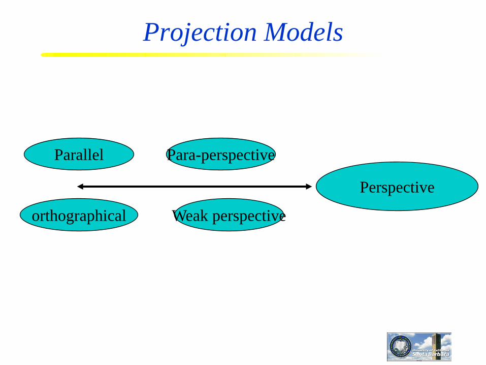
Projection Models
Perspective
Parallel
orthographical
Para-perspective
Weak perspective

360 degree field of view…
Basic approach Take a photo of a parabolic mirror with an orthographic lens (Nayar)
Or buy one a lens from a variety of omnicam manufacturers…
See http://www.cis.upenn.edu/~kostas/omni.html
S. Seitz

Tilt-shift
Titlt-shift images from Olivo Barbieri
and Photoshop imitations
http://www.northlight-images.co.uk/article_pages/tilt_and_shift_ts-e.html
S. Seitz

tilt, shift
http://en.wikipedia.org/wiki/Tilt-shift_photography
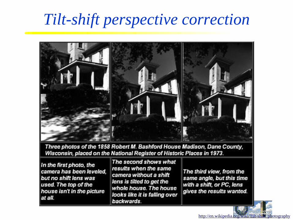
Tilt-shift perspective correction
http://en.wikipedia.org/wiki/Tilt-shift_photography

normal lens tilt-shift lens
http://www.northlight-images.co.uk/article_pages/tilt_and_shift_ts-e.html

Rollout Photographs © Justin Kerr
http://research.famsi.org/kerrmaya.html
Rotating sensor (or object)
Also known as “cyclographs”, “peripheral images”
S. Seitz

Summary
Two variations
Direction: parallel rays but do not have to be parallel to the optical
axis
“Average” distance: object is roughly planar on a plane that is
parallel to the image plane. Division by z is not necessary
Why?
Linearity
Examples
Carlo Tomasi and Takeo Kanade. (November 1992.). "Shape and
motion from image streams under orthography: a factorization
method.". International Journal of Computer Vision, 9 (2): 137–
154

Factorization Method
M: camera poses
S: object structures

Planar and spherical projection
What do straight lines map onto under spherical perspective projection?

Pinhole too big -
many directions are
averaged, blurring the
image
Pinhole too small-
diffraction effects blur
the image
Generally, pinhole
cameras are dark, because
a very small set of rays
from a particular point
hits the screen.

The reason for lenses

Optical Image Formation
Image formation is achieved with a lens system integrated
with optical elements which alter light, such as prisms and
mirrors
Lens – a transparent element, usually made of glass
Surfaces are usually spherically ground and polished
Refraction at surfaces “bends” the light rays and focuses them
The refracting power of a lens is related to its focal point

Light and Optics
Optics – The branch of physics that deals with light
Ray optics
Wave optics
Photon optics
Light – The visible portion of the electromagnetic
spectrum; visible radiant energy
We’re also interested in other parts of the EM spectrum (e.g., X-
rays, UV rays, infrared)

Electromagnetic (EM) Spectrum
Energy, frequency, and wavelength
are related

Reflection and Refraction
At the interface between media, there is reflection and
refraction (and absorption)
Reflection – light is reflected from the surface
Refraction – light proceeds through the material in a different
direction, depending on the index of refraction
Incident ray
Reflected ray
Refracted ray
Normal
i
r
Air
Glass

Refraction
Refraction occurs toward the normal when light enters a
more dense medium
Medium characterized by its index of refraction (n)
Index of refraction defined as n = c / vm
Snell’s Law for refraction: n1 sin (i) = n2 sin (r)
Refracted ray
i
r
Air
Glass

Lens refraction causes points to
focus

Thick Lens

Thin Lens
The thin lens model is an ideal approximation to a lens
Disregard the lens thickness
Disregard blurring (rays don’t really converge)
All light bending takes place at the principal plane, where the
incoming rays intersect with the outgoing rays
Principal plane
Real lens Ideal lens

Focal Point
21
11)1(
1
rrn
f
Focal distance is a function of the index of refraction
(n) and the surface radii for the two sides of the lens

Thin Lens Equation
z
0z z’
fzz
111
z – distance of point/object from lens origin (positive outside)
z’ – distance from lens origin where point/object is in focus
(positive inside)
f – focal distance (constant property of the lens, positive convex,
negative concave)
object image
(Careful about signs!)

Focus
z
0z z’
So everything in the plane Z=z will be imaged (focused) at Z=z’
Everything else will be out of focus (sort of)
object image
fzz
111

Aperture
An aperture limits the area that light can pass through
object imageobject image

Relation to Pin Hole Model
f f
Z
Z’
Z
XZX
fZZ
''
1
'
11
X
X’

Image Formation
In general
A pin-hole model
fZfZfZ
fZ '1
'
111,
f
Z
Z’
X
Z
YfY
Z
XfX
'
'
X’

Image Formation (cont.)
A pin-hole model without inversion
Back to old pinhole camera formula
f
Z
X
Z
YfY
Z
XfX
'
'
f X’
X’

Focus and depth of field
Image credit: cambridgeincolour.com

Focus and depth of field
Depth of field: distance between image planes where
blur is tolerable
Thin lens: scene points at
distinct depths come in
focus at different image
planes.
(Real camera lens
systems have greater
depth of field.)
Shapiro and Stockman
“circles of confusion”

Focus and depth of field
How does the aperture affect the depth of field?
• A smaller aperture increases the range in which the object
is approximately in focus
Flower images from Wikipedia http://en.wikipedia.org/wiki/Depth_of_field Slide from S. Seitz

Depth from focus
Images from
same point of
view, different
camera
parameters
3d shape / depth
estimates

Field of view
Angular
measure of
portion of 3d
space seen by
the camera
Images from http://en.wikipedia.org/wiki/Angle_of_viewK. Grauman

As f gets smaller, image becomes more wide angle
more world points project onto the finite image plane
As f gets larger, image becomes more telescopic
smaller part of the world projects onto the finite image plane
Field of view depends on focal length
from R. Duraiswami

Field of view depends on focal length
Smaller FOV = larger Focal LengthSlide by A. Efros

Lens Aberrations
Aberrations: Systematic deviations from the ideal path of
the image-forming rays
Causes blur and other problems in the image
Good optical design minimizes aberrations (but doesn’t eliminate
them!)
Typically small effect for paraxial rays
Types:
Spherical aberration
Coma
Astigmatism
Distortion
Chromatic aberration

Lens Aberrations
Longitudinal and lateral (transverse) effects
Ideal Real

Spherical Aberration
The spherical lens shape does not really effect perfect focusing. However:
It works reasonably well
It is by far the easiest to fabricate and measure
It is used in all but the most demanding situations
Spherical aberration causes different focal lengths for light rays entering at different parts of the lens (varies with radial distance)
a longitudinal aberration
Effects can be reduced by using two lenses together, convex and concave
Blurs the image
Proportional to the diameter of the lens

Coma
Coma is the aberration resulting in varying focal length for rays which
originate off the axis of the lens
Similar to spherical aberration, but for off-axis object/image points
Rim rays come to focus nearer the axis than do rays passing near the
center of the lens
a transverse aberration
Coma results in a clearly defined geometrical shape (not a general
blur) – comet-shaped (or teardrop-shaped)
Proportional to the square of the aperture

Astigmatism
Astigmatism is caused by the lens not having a perfectly spherical
shape
Different curvature in different cross-sections (e.g., a football or a
boat hull)
Horizontal and vertical edges/stripes focus differently
Result of poor lens grinding


Radial distortion
Variation in the magnification for object points at different distances
from the optical axis
Effect increases with distance from the optical axis
Straight lines become bent!
Two main descriptions: barrel distortion and pincushion distortion
Can be modeled and corrected for
Barrel PincushionCorrect


Correcting for radial distortion
Original Corrected

Chromatic Aberration
The index of refraction varies with wavelength (called dispersion)
Shorter wavelengths are bent more
This causes longitudinal chromatic aberration – shorter wavelength
rays focus closer to the lens
Another effect is lateral chromatic aberration – shorter wavelength
rays focus closer to the optical axis
Can be reduced by using two lenses together, convex and concave
Longitudinal Lateral

Paraxial rays
Lenses are not perfect – they cause blurring
But in many cases, the blurring is minimal
Minimal blurring occurs when viewing only paraxial rays
Paraxial rays – Rays which make a small angle with the
central axis (in this case, perpendicular to the interface)
Paraxial rays in red

Vignetting
Vignetting is the darkening of the corners of an image
relative to its center, due to the use of multiple lenses
Lost rays

Vignetting
http://www.ptgui.com/examples/vigntutorial.htmlhttp://www.tlucretius.net/Photo/eHolga.html

Image irradiance on the image plane
The image irradiance (E) is proportional to the object radiance
(L)
Lf
dE
4
2
cos4
Lens diameter
Focus distance
Angle off optical axis
What the image reports to us
via pixel values
What we really want to know
cos4 α – 4th power contributes to vignetting!
Lk )(

Lens lessons
No lens is perfect
Even a perfectly-shaped lens is not perfect!
Monochromatic light images best
Good optical design (multiple lenses) and good
craftsmanship (careful and precise lens grinding) can
reduce aberration effects
Paraxial rays are your best bet
Some effects are only noticeable at high resolution

Blur due to misfocus

Depth of Focus/Field
In addition to lens aberrations, blur is caused by having the
imager (sensor array) too close or too far – away from
where the point is focused
Depending on sensor resolution, small amounts of blur
may not matter
sensor
placement
resulting
images

Depth of Focus/Field
Depth of focus – the distance of the imager along the axis where a
single object point produces a focused image point
Depth of field – the distance of the object point along the axis
d
Pixel spacing

Depth of Focus
Aperture size affects depth of focus/field

Film Exposure
Right amount of light depends on
Shutter speed – how long is the exposure
f/stop – how much light is allowed through the lens
Film speed – sensitivity of the film
Shutter speed
Measured in seconds (or fraction of a second)
Neighboring setting either half or double the exposure time
8,4,2,1,1/4,1/8,1/15,1/30,1/60,1/125,1/250,1/500,1/1000

F/stops
Popular settings are f/1.4,f/2.0,f/2.8,f/4,f/5.6,f/8,f/11,f/16,f/22
From brighter (f/1.4) to darker (f/22)
Neighboring settings half or double the amount of light
entering the camera
focal length/iris diameter = f/stops
E.g. 50mm/25mm=f/2, so aperture diameter is half the focal length
F=50mm
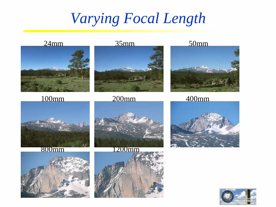
Varying Focal Length
24mm 35mm 50mm
100mm 200mm 400mm
800mm 1200mm

Calibrating for radial distortion
The camera lens also introduces errors of several type (as
we’ve already discussed):
Spherical aberration
Coma
Chromatic aberration
Vignetting
Astigmatism
Misfocus
Radial distortion
Of these, radial distortion is the most significant in most
systems, and it can be corrected for

Radial distortion
Variation in the magnification for object points at different distances
from the optical axis
Effect increases with distance from the optical axis
Straight lines become bent!
Two main descriptions: barrel distortion and pincushion distortion
Can be modeled and corrected for
Barrel PincushionCorrect


Correcting for radial distortion
Original Corrected

Modeling Lens Distortion
Radial, Barrel, Pincushion, etc.
Modeled as bi-cubic (or bi-linear) with more parameters to
compensate for
Very hard to solve
1
12
3
444241
242221
141211
23
ideal
ideal
ideal
xxx
xxx
xxx
idealidealidealrealy
y
y
aaa
aaa
aaa
xxxx

Modeling radial distortion
The radial distortion can be modeled as a polynomial
function () of d2, where d is the distance between the
image center and the image point
Called the radial alignment constraint
v
ud
v
u
d
d)(
e.g., (d) = 1 + 1d2 + 2d
4 + 3d6
q distortion coefficients (q <4)

Less Frequently Used –
Tangential Distortion Less common
Radial
Tangential

Modeling distortion
Now do calibration by estimating the 11+q parameters
P0
TRK
1
100
0)','(
10
00)','(
1
1
Tvu
vu
v
u
Since d is a function of u and v, we could also write as
(u, v)
where (u’, v’) comes from K[R|T]P