image morphing 15-463: computational photography alexei efros, cmu, fall 2005 © alexey tikhonov
Post on 21-Dec-2015
219 views
TRANSCRIPT

Image Morphing
15-463: Computational PhotographyAlexei Efros, CMU, Fall 2005
© Alexey Tikhonov

Recovering Transformations
What if we know f and g and want to recover the transform T?• e.g. better align images from Project 1• willing to let user provide correspondences
– How many do we need?
x x’
T(x,y)y y’
f(x,y) g(x’,y’)
?

Translation: # correspondences?
How many correspondences needed for translation?
How many Degrees of Freedom?
What is the transformation matrix?
x x’
T(x,y)y y’
?
100
'10
'01
yy
xx
pp
pp
M

Euclidian: # correspondences?
How many correspondences needed for translation+rotation?
How many DOF?
x x’
T(x,y)y y’
?

Affine: # correspondences?
How many correspondences needed for affine?
How many DOF?
x x’
T(x,y)y y’
?

Projective: # correspondences?
How many correspondences needed for projective?
How many DOF?
x x’
T(x,y)y y’
?

Example: warping triangles
Given two triangles: ABC and A’B’C’ in 2D (12 numbers)
Need to find transform T to transfer all pixels from one to the other.
What kind of transformation is T?
How can we compute the transformation matrix:
T(x,y)
?
A
B
C A’C’
B’
Source Destination
11001
'
'
y
x
fed
cba
y
x

HINT: warping triangles
Very useful for Project 2…
A
B
C A’C’
B’
Source Destination
(0,0) (1,0)
(0,1)
changeof basis
Inverse changeof basis
Don’t forget to move the origin too!
2T11T

Morphing = Object Averaging
The aim is to find “an average” between two objects• Not an average of two images of objects…• …but an image of the average object!• How can we make a smooth transition in time?
– Do a “weighted average” over time t
How do we know what the average object looks like?• We haven’t a clue!• But we can often fake something reasonable
– Usually required user/artist input

P
Qv = Q - P
P + 0.5v= P + 0.5(Q – P)= 0.5P + 0.5 Q
P + 1.5v= P + 1.5(Q – P)= -0.5P + 1.5 Q(extrapolation)Linear Interpolation
(Affine Combination):New point aP + bQ,defined only when a+b = 1So aP+bQ = aP+(1-a)Q
Averaging Points
P and Q can be anything:• points on a plane (2D) or in space (3D)• Colors in RGB or HSV (3D)• Whole images (m-by-n D)… etc.
What’s the averageof P and Q?

Idea #1: Cross-Dissolve
Interpolate whole images:
Imagehalfway = (1-t)*Image1 + t*image2
This is called cross-dissolve in film industry
But what is the images are not aligned?

Idea #2: Align, then cross-disolve
Align first, then cross-dissolve• Alignment using global warp – picture still valid

Dog Averaging
What to do?• Cross-dissolve doesn’t work• Global alignment doesn’t work
– Cannot be done with a global transformation (e.g. affine)
• Any ideas?
Feature matching!• Nose to nose, tail to tail, etc.• This is a local (non-parametric) warp

Idea #3: Local warp, then cross-dissolve
Morphing procedure: for every t,1. Find the average shape (the “mean dog”)
• local warping
2. Find the average color• Cross-dissolve the warped images

Local (non-parametric) Image Warping
Need to specify a more detailed warp function• Global warps were functions of a few (2,4,8) parameters• Non-parametric warps u(x,y) and v(x,y) can be defined
independently for every single location x,y!• Once we know vector field u,v we can easily warp each pixel
(use backward warping with interpolation)

Image Warping – non-parametricMove control points to specify a spline warp
Spline produces a smooth vector field

Warp specification - denseHow can we specify the warp?
Specify corresponding spline control points• interpolate to a complete warping function
But we want to specify only a few points, not a grid
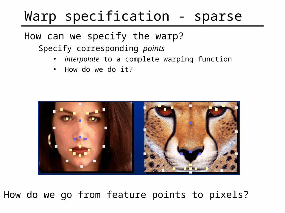
Warp specification - sparseHow can we specify the warp?
Specify corresponding points• interpolate to a complete warping function
• How do we do it?
How do we go from feature points to pixels?

Triangular Mesh
1. Input correspondences at key feature points
2. Define a triangular mesh over the points• Same mesh in both images!• Now we have triangle-to-triangle correspondences
3. Warp each triangle separately from source to destination• How do we warp a triangle?• 3 points = affine warp!• Just like texture mapping

TriangulationsA triangulation of set of points in the plane is a partition
of the convex hull to triangles whose vertices are the points, and do not contain other points.
There are an exponential number of triangulations of a point set.

An O(n3) Triangulation AlgorithmRepeat until impossible:
• Select two sites.• If the edge connecting them does not intersect previous
edges, keep it.

“Quality” Triangulations
Let (T) = (1, 2 ,.., 3t) be the vector of angles in the triangulation T in increasing order.
A triangulation T1 will be “better” than T2 if (T1) > (T2) lexicographically.
The Delaunay triangulation is the “best” • Maximizes smallest angles
good bad

Improving a TriangulationIn any convex quadrangle, an edge flip is possible. If
this flip improves the triangulation locally, it also improves the global triangulation.
If an edge flip improves the triangulation, the first edge is called illegal.

Illegal Edges
Lemma: An edge pq is illegal iff one of its opposite vertices is inside the circle defined by the other three vertices.
Proof: By Thales’ theorem.
Theorem: A Delaunay triangulation does not contain illegal edges.
Corollary: A triangle is Delaunay iff the circle through its vertices is empty of other sites.
Corollary: The Delaunay triangulation is not unique if more than three sites are co-circular.
p
q

Naïve Delaunay Algorithm
Start with an arbitrary triangulation. Flip any illegal edge until no more exist.
Could take a long time to terminate.

Delaunay Triangulation by Duality
General position assumption: There are no four co-circular points.
Draw the dual to the Voronoi diagram by connecting each two neighboring sites in the Voronoi diagram.
Corollary: The DT may be constructed in O(nlogn) time.
This is what Matlab’s delaunay function uses.

Image MorphingWe know how to warp one image into the other, but how
do we create a morphing sequence?1. Create an intermediate shape (by interpolation)
2. Warp both images towards it
3. Cross-dissolve the colors in the newly warped images

Warp interpolationHow do we create an intermediate warp at time t?
• Assume t = [0,1]• Simple linear interpolation of each feature pair• (1-t)*p1+t*p0 for corresponding features p0 and p1

Other Issues
Beware of folding• You are probably trying to do something 3D-ish
Morphing can be generalized into 3D• If you have 3D data, that is!
Extrapolation can sometimes produce interesting effects• Caricatures

Dynamic Scene

Project #2: Due Tu, Sept 27
• Given two photos, produce a 60-frame morph animation• Use triangulation-based morphing (lots of helpful Matlab tools)• Need to write triangle-to-triangle warp (can’t use Matlab tools)
• We put all animations together into a movie!
Last year’s movie