immobilizationofstablethylakoidvesiclesinconductivenanofibe ... = 625 nm), green (520 nm), or purple...
TRANSCRIPT

Published: January 21, 2011
r 2011 American Chemical Society 778 dx.doi.org/10.1021/bm101386w | Biomacromolecules 2011, 12, 778–784
ARTICLE
pubs.acs.org/Biomac
Immobilization of Stable Thylakoid Vesicles in Conductive Nanofibersby ElectrospinningNicholas M. Bedford,†,‡ G. Douglas Winget,|| Srikoundinya Punnamaraju,†,§ and Andrew J. Steckl*,†,§
†Nanoelectronics Laboratory, ‡Department of Chemical and Materials Engineering, and §Department of Electrical and ComputerEngineering, University of Cincinnati, Cincinnati, Ohio 45221-0030, United States
)The Center for Conservation and Research of Endangered Wildlife, 3400 Vine Street, Cincinnati, Ohio, 45220-1399, United States
ABSTRACT: Electrospun fibers consisting of poly(3,4-ethylenedioxythiophene)/poly(styrene sulfonate) (PEDOT/PSS) and poly(ethylene oxide) (PEO) have been used tosuccessfully encapsulate and stabilize thylakoid membranevesicles isolated from spinach. Light-driven electronic pro-perties were measured. Fibers with immobilized thylakoidsshow higher electrical conductivity compared with fiberswithout thylakoids under white light conditions. This isattributed to the electron-generating photosynthetic reac-tions from the thylakoids. Electron and optical microscopyshow the presence of thylakoid vesicles within the fibersusing lipid-specific stains. After electrospinning into fibers,the thylakoid vesicles still exhibit an ability to produce alight-driven electron gradient, indicating that activity is preserved during the electrospinning process. These electrospun fibersprovide an excellent example of incorporating photosynthetic function into an artificial system.
1. INTRODUCTION
Photosynthetic biological materials recently have been receiv-ing much attention1 for potential use in optoelectronic, organicphotovoltaic (OPV), and sensor applications given their superiorphotoresponsive properties and inherent biodegradability/re-newability. The structural hierarchy of available photosyntheticmaterials starts with the chromophore (such as chlorophyllmolecules, derivatives of chlorophyll, and other accessorypigments) and moves up to the pigment-containing membrane-spanning proteins (such as photosystems I and II in plants andreaction center in bacteria). These proteins are part of a doublemembrane envelope called the thylakoid membrane (or simplythylakoid), which houses the light reactions of photosynthesisthat are ultimately responsible for the synthesis of ATP inphotosynthetic species (inset, Figure 1).2 Biological photosyn-thetic chromophores have been previously used in the fabricationof OPVs3 and dye-sensitized solar cells,4-7 whereas photosystems and reaction centers have shown promise in OPVs/photoelectronic8-15 and sensors applications.16,17 The inclusionof larger structural units such as thylakoids in a material’s matrixis of particular interest because the encapsulation of intact andfunctioning thylakoids would be a step toward a photosynthetic“living material”.18 Previously, thylakoids embedded in a silicamatrix were shown to have improved activity when comparedwith a free thylakoid suspension,19 whereas thylakoids immobi-lized in a cross-linked albumin-glutaraldehyde have exhibited theability to detect herbicides.20
Electrospinning21,22 is an established method for creatingcontinuous fibers ranging from tens of nanometers to micro-meters in diameter. This is accomplished by applying a highvoltage between a droplet of solution at the end of a spinneretand a collecting substrate. Under the proper conditions (solutionconductivity, viscosity, etc.), the applied electric field causes aliquid jet to eject from the droplet toward the collectingsubstrate. During this process, the jet quickly elongates, reducesin diameter, and loses solvent, resulting in a nonwoven mesh offibers with high surface-to-volume ratio. Previously it has beendemonstrated that biological macrostructures such as livingcells,23 bacteria,24-27 viruses,28 and enzymes29,30 can be incorpo-rated into electrospun fibers while still retaining their biologicalfunction.
In this work, electrospinning is used to create nanofibers froma solution of thylakoids, poly(3,4-ethylenedioxythiophene)/poly(styrene sulfonate) (PEDOT/PSS, herein referred to asPEDOT), and poly(ethylene oxide) (PEO). By immobilizingthylakoids into electrically conductive PEDOT/PEO nanofibers,changes in electronic properties with response to light can bemeasured. These nanofibers exhibit light-induced changes inelectronic properties attributed to the photosystems insidethe thylakoids. Transmission electron micrographs show that
Received: November 22, 2010Revised: December 22, 2010

779 dx.doi.org/10.1021/bm101386w |Biomacromolecules 2011, 12, 778–784
Biomacromolecules ARTICLE
thylakoid vesicles are present within the fibers, whereas lipid-specific fluorescence staining also indicates the presence of astable lipophilic environment within the nanofibers. The viabilityof the thylakoids during the fiber formation process was tested bymeasuring light-induced pH change prior to and after electro-spinning. To the authors’ knowledge, this study represents thefirst attempt to encapsulate and immobilize active thylakoids intoelectrospun fibers, which could potentially be used in optoelec-tronic applications.
2. EXPERIMENTAL SECTION
2.1. Thylakoid Isolation. The thylakoid isolation was adaptedfrom Izawa and Good.31 In brief, spinach leaves were washed anddeveined, then homogenized in a Waring blender three times for 10 seach in a cold aqueous solution of 2mMNa2EDTA, 40mMK2HPO4, 10mM KH2PO4, and 0.35 mM NaCl. The homogenate was filteredthrough four layers of cheesecloth and centrifuged at 3000g for 5 min.All centrifugation steps were performed at 4 �C (Sorvall RC6 Plus). Theresulting pellet was then suspended in a cold solution of 0.2 M sucrose,50 mM tricine, 3 mMKCl, and 3 mMMgCl2 and centrifuged at 750g for1 s. The supernatant was then filtered and centrifuged at 3000g for 5min.The pellet was resuspended in the same tricine buffer solution andcentrifuged again at 3000g for an additional 5 min. The supernatant wasdecanted, and pellets were concentrated in the tricine buffer solution at achlorophyll (chl) concentration of ∼25 mg/mL, as determined usingthe method of Arnon.32
2.2. Solution Preparation. In a typical procedure, 10 mL ofaqueous PEDOT solution (HC Starck, under the trade name Clevios P)was evaporated until it reached a solid form under vacuum at 35 �C,resulting in∼100mg of solidmaterial. This solid was then redispersed in2.25 mL of deionized H2O by vortex mixing and magnetic stirring for atleast 1 h, followed by the addition of 2.5 mL of ethanol. After theaddition of 0.045 g of PEO (Acros, MW = 900 000 g/mol) to the
dispersion, it was vigorously mixed by magnetic stirring for at least 8 h.PEO is added to the solution to assist in electrospun fiber formation.The motivation for concentrating the initial PEDOT solution was toincrease the ratio of PEDOT/PEO, which increases the overall electricalconductivity. Where appropriate, 1 mL of the isolated thylakoid solutionwas added and allowed to stir in the polymer blend for 15 min prior toelectrospinning. The thylakoid solution was increased to 1.513 mL forosmium tetroxide (OsO4)-stained samples used in TEM analysis. Thestained thylakoid solution consisted of 0.5 mL of as-isolated thylakoidsolution, 0.5 mL of 4% paraformaldehyde (Acros) in 23 mMNaH2PO4/77 mM Na2HPO4 buffer, 13 μL of 8% glutaric dialdehyde (Acros), and0.5 mL of 4 wt % OsO4 (Acros). The solution was incubated for 30 minat 4 �Cafter the addition of the fixation agents to the thylakoids. This wasfollowed by an additional 30 min incubation period at 4 �C after OsO4
was added to the solution. For fluorescence testing, a stock solution ofNile red dye (Acros) was made in acetone at 1 mg/mL and added toelectrospinning solutions at a final dye concentration of 50 μg/mL. Allsolutions for light-induced pH measurements had an addition of K3[Fe-(CN)6] to a concentration of 0.3 mM for electron transfer purposes.Isolated thylakoid solutions and electrospinning solutions were used as-is(with the exception of the K3[Fe(CN)6]) while electrospun fibers wereredissolved in the isolation buffer medium to a final volume of 10 mL.2.3. Electrospinning. The electrospinning apparatus consisted of
a high-voltage power supply (Gamma High Voltage), a syringe pump(Stoelting), a spinneret, and a 5 � 5 cm2 aluminum collecting plate.Electrospinning solutions were fed into an 18 gauge blunt needle at a ratebetween 0.1 and 0.3 mL/h. A positive voltage of 25 kV was appliedbetween the spinneret and an aluminum collecting ground electrodeseparated by a distance of 20 cm. For electrical testing, fibers were collectedon glass substrates with aluminummicropatterned electrodes separated by100 μm. The glass substrate was placed on top of the aluminum collector.All electrospinning experiments were performed at room temperature.2.3. Light-Dependent Electrical Measurements. Fibers
were electrospun directly onto precleaned glass slides with micropat-terned Al electrodes with an electrode spacing of 100 μm. The sameamount of material (200 μL) was used for each experiment to bettercontrol the amount of electrospun fibers on the device substrates.Because of the random landing of fibers during the electrospinningprocess, the location and distribution of the deposited fibers on the Al-patterned substrates inevitably changed to some degree from experi-ment to experiment. Given the difficulty of measuring the amount offibers between the electrodes for each experiment, all electrical measure-ments were normalized to a value of 100, corresponding to themaximum value recorded. Electrical current levels were typically onthe order of several hundred microamperes. All light-dependent elec-trical measurements were performed using a Hewlett-Packard 4140Bammeter/DC voltage source with LabView data acquisition softwareusing probe manipulators (Cascade Microtech). Silver paste was used toenhance the connection between the Al electrodes and probes. A SchottACE 1 halogen light source was used for all white light experiments at apower density of ∼13 mW/cm2. When red (λp = 625 nm), green (520nm), or purple (470 nm) filters were used, the power density was ∼24,∼7, or ∼14 mW/cm2, respectively. All electrical characterization wasdone under ambient conditions and repeated multiple times to ensuregood reproducibility.2.4. Characterization. Fiber morphology and thylakoid mem-
brane inclusion were studied using a Phillips CM20 transmissionelectron microscope operating at 80 kV. Fluorescence imaging wasdone on a Nikon Eclipse Ti-U fluorescence inverted microscope usinga Texas Red filter cube and analyzed using the Image J program.33 Light-induced pH measurements were done using a MeasureNet pH meterand data acquisition software (MeasureNet Technology, Ltd.). We used10 μL of 0.1 N HCl to calibrate the change in proton concentration foreach solution tested.
Figure 1. Photograph of the electrical testing experiment, with dia-grams of the micropatterned substrates and the light reactions of thephotosynthesis within the thylakoids. Spacing between the electrodes is100 μm. For reference: photosystem I (PS-I), photosystem II (PS-II),plastoquinone (PQ), reduced plastoquinone (PQH2), plastocyanin(PC), ferredoxin (Fd), ferredoxin-NADP-reductase (FNR), adenosinediphosphate (ADP), adenosine triphosphate (ATP), and phosphate(Pi). Proton movement is shown in blue solid lines, and electron move-ment is shown in black dashed lines.2.

780 dx.doi.org/10.1021/bm101386w |Biomacromolecules 2011, 12, 778–784
Biomacromolecules ARTICLE
3. RESULTS AND DISCUSSION
PEDOT/PEO fibers with and without the inclusion of thyla-koids were electrospun onto micropatterned Al-electrodes with anelectrode gap distance of 100 μm (inset, Figure 1). Light-inducedchanges in electrical properties were then measured using themicroprobe station shown in Figure 1. The light-dependent I-Vsweeps are shown in Figure 2 for PEDOT/PEO fibers without(Figure 2a) and with (Figure 2b) the inclusions of thylakoids. Forfibers without thylakoids, there is a drop in electrical conductivityunder white light illumination (compared with dark conditions) athigher voltages. This reduction in electrical conductivity is likelydue to the degradation of PEDOT under light and the ambienttesting conditions.34,35 When thylakoids are added to the elec-trospun fibers, this trend is reversed, with slightly higher electricalconductivities reached under white light illumination.
The concentration of thylakoids in the electrospinning solu-tion was varied to examine the effect of thylakoids on the overallphotocurrent (Figure 3). The normalized differences in photo-current measured at the maximum voltage increase monotonicallywith thylakoid concentration. Theminimum thylakoid concentration
needed to produce an increase in photocurrent was foundto be ∼2 mg/mL (in chl). The effect of power density on thephotocurrent was also examined (Figure 3). Unsurprisingly,it was found that a larger power density produced a higherphotocurrent response for each thylakoid concentration tested.At power densities lower than 1 mW/cm2, the change in photo-current was negligible. Therefore, to produce a measurable photo-current, a power density >1 mW/cm2 must be used on fiberselectrospun from a solution containing a chl concentration of atleast 2 mg/mL. For reference, the changes in PEDOT/PEO fiberfor both power densities are also shown in Figure 3.
The electrical current response to a train of light pulses wasevaluated for PEDOT/PEO fibers with and without thylakoidsfor several wavelength regimes (Figure 4). The voltage was heldat þ5 V, and light was pulsed on and off at 3 min intervals(Figure 4, blue dashed lines). Under white light exposure(Figure 4a), the PEDOT/PEO fibers with immobilized thyla-koids display a gradual increase (decrease) in current during(after) exposure. The current response is roughly constant withsequential light pulses. Fibers without thylakoids (Figure 4b)show no marked changes in current coincident with lightexposure and exhibit only a slight overall decrease throughoutthe duration of the experiment.
Figure 2. I-V sweeps of (a) PEDOT/PEO fibers and (b) PEDOT/PEO þ thylakoid fibers under white light illumination.
Figure 3. Maximum photocurrent versus the initial chl concentration insolution for 13 (squares, black line) and 3 mW/cm2 (circles, red line).
Figure 4. Current versus time measurements with response to light for(a) PEDOT/PEO/thylakoid fibers under white light, (b) PEDOT/PEOfibers under white light, (c) PEDOT/PEO/thylakoid fibers underred light, (d) PEDOT/PEO/thylakoid fibers under purple light, and(e) PEDOT/PEO/thylakoid fibers under green light. The dashed linecorresponds to light being on or off.

781 dx.doi.org/10.1021/bm101386w |Biomacromolecules 2011, 12, 778–784
Biomacromolecules ARTICLE
The wavelength dependence of the observed increases inphotocurrent for the PEDOT/PEO/thylakoid fibers is shownin Figure 4c-e. The wavelength regimes selected correspondto the main absorption regions for both chlorophyll a andchlorophyll b (red and purple), as well as a green wavelengthregion where the two chromophores do not absorb light.36 Ascan be seen in Figure 4c-e, light of all selected wavelengthregions does not produce the same electrical response as doeswhite light. Relatively small current increases were observed atthe moment of illumination. A general decrease in current wasobserved as the experiment progressed.
The wavelength sensitivity can be attributed to the interplaybetween the distinct photosynthetic pigments during the energytransfer processes of photosynthesis and their correspondingabsorption of light in the visible spectrum. For an electron to begiven off in photosynthesis, light is first absorbed by variouspigments in the antenna complexes within the photosystem.These pigments, each with their own absorption characteristics,transfer the excitation energy via fluorescence resonance energytransfer (FRET) to a pair of chlorophyll molecules, which then inturn produces a free electron. Absence of photon absorption byany pigment in the photosystem would prevent the energytransfer process. This would then severely reduce the efficiencyof generating free electrons and thus prevent an increase inelectrical current in the electrospun fibers during illumination.This is analogous to the Emerson enhancement effect.37 Thephotocurrent response (on the order of minutes) observed forwhite light illumination is much slower than the electron transferprocesses seen in photosystem proteins (∼200 ps)2. Thisindicates that the photoresponse is not rate-limited by thephotosystems, but likely by the electron transfer from thylakoidto the fiber material. Nonetheless, these findings clearly showthat photocurrent is observed only in the presence of thylakoidsin the fibrous material and during exposure to a white lightsource.
The PEDOT/PEO fiber morphology and immobilization ofthylakoids into PEDOT/PEO fibers and was studied using TEM(Figure 5). The single PEDOT/PEO fiber shown in Figure 5ahas a diameter of ∼100 nm. With thylakoids added to theelectrospinning solution, the resulting fiber diameter is approxi-mately the same (Figure 5b), although a clear variation incontrast is present along the fiber. The ovular shapes are theimmobilized thylakoids, as they are less dense then the polymericfibers and thus exhibit a lighter shading in the TEM micrograph.It is interesting to point out that the thylakoids tend to arrangethemselves perpendicular to the fiber axis. Many other reports38-41
of high aspect ratio particles in electrospun fibers display analignment along the fiber axis. To confirm that these vesicles areindeed thylakoids, we added the lipid stain OsO4 and fixationagents to the thylakoid solution prior to electrospinning, asmentioned in the Experimental Section (Figure 5c). The per-iphery of the vesicles is clearly darker in contrast with theaddition of OsO4, indicating that a lipid environment is present,which is likely the structurally intact thylakoids. The density ofthe thylakoids in certain regions of the fibers also becomes higherbecause of the addition of cross-linking moieties in the stainedthylakoid solution. The inclusion of the OsO4 stained thylakoidshas a drastic effect on electrospun fiber morphology because thefibers become more beaded in nature and electrosprayingbecomes more prevalent. A single isolated thylakoid from thestarting solution is shown in Figure 5d for reference.
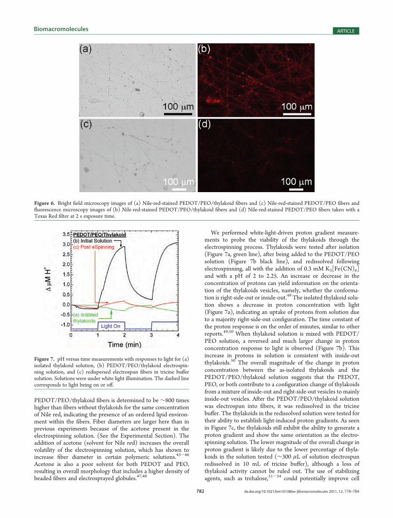
To investigate further whether stable thylakoids were presentin the electrospun PEDOT/PEO fibers, the lipid-specific dyeNile red42 was added to the electrospinning solutions. Invertedfluorescence microscopy images of fibers with and withoutthylakoids are shown in Figure 6b,d, respectively. Correspondingbright field images are shown in Figure 6a,c. Comparing theimages, it is clear that the fluorescence is much stronger infibers where thylakoids were included in the electrospinningsolution. Using gray scale analysis, the fluorescence of the
Figure 5. TEM micrographs of (a) PEDOT/PEO fibers, (b) PEDOT/PEO/thylakoids fibers, (c) PEDOT/PEO/thylakoid fibersþ OsO4 and fixingagents, and (d) an as isolated thylakoid vesicle.
782 dx.doi.org/10.1021/bm101386w |Biomacromolecules 2011, 12, 778–784
Biomacromolecules ARTICLE
PEDOT/PEO/thylakoid fibers is determined to be ∼800 timeshigher than fibers without thylakoids for the same concentrationof Nile red, indicating the presence of an ordered lipid environ-ment within the fibers. Fiber diameters are larger here than inprevious experiments because of the acetone present in theelectrospinning solution. (See the Experimental Section). Theaddition of acetone (solvent for Nile red) increases the overallvolatility of the electrospinning solution, which has shown toincrease fiber diameter in certain polymeric solutions.43-46
Acetone is also a poor solvent for both PEDOT and PEO,resulting in overall morphology that includes a higher density ofbeaded fibers and electrosprayed globules.47,48
We performed white-light-driven proton gradient measure-ments to probe the viability of the thylakoids through theelectrospinning process. Thylakoids were tested after isolation(Figure 7a, green line), after being added to the PEDOT/PEOsolution (Figure 7b black line), and redissolved followingelectrospinning, all with the addition of 0.3 mM K3[Fe(CN)6]and with a pH of 2 to 2.25. An increase or decrease in theconcentration of protons can yield information on the orienta-tion of the thylakoids vesicles, namely, whether the conforma-tion is right-side-out or inside-out.49 The isolated thylakoid solu-tion shows a decrease in proton concentration with light(Figure 7a), indicating an uptake of protons from solution dueto a majority right-side-out configuration. The time constant ofthe proton response is on the order of minutes, similar to otherreports.49,50 When thylakoid solution is mixed with PEDOT/PEO solution, a reversed and much larger change in protonconcentration response to light is observed (Figure 7b). Thisincrease in protons in solution is consistent with inside-outthylakoids.50 The overall magnitude of the change in protonconcentration between the as-isolated thylakoids and thePEDOT/PEO/thylakoid solution suggests that the PEDOT,PEO, or both contribute to a configuration change of thylakoidsfrom amixture of inside-out and right-side-out vesicles to mainlyinside-out vesicles. After the PEDOT/PEO/thylakoid solutionwas electrospun into fibers, it was redissolved in the tricinebuffer. The thylakoids in the redissolved solution were tested fortheir ability to establish light-induced proton gradients. As seenin Figure 7c, the thylakoids still exhibit the ability to generate aproton gradient and show the same orientation as the electro-spinning solution. The lower magnitude of the overall change inproton gradient is likely due to the lower percentage of thyla-koids in the solution tested (∼300 μL of solution electrospunredissolved in 10 mL of tricine buffer), although a loss ofthylakoid activity cannot be ruled out. The use of stabilizingagents, such as trehalose,51-54 could potentially improve cell
Figure 6. Bright field microscopy images of (a) Nile-red-stained PEDOT/PEO/thylakoid fibers and (c) Nile-red-stained PEDOT/PEO fibers andfluorescence microscopy images of (b) Nile-red-stained PEDOT/PEO/thylakoid fibers and (d) Nile-red-stained PEDOT/PEO fibers taken with aTexas Red filter at 2 s exposure time.
Figure 7. pH versus time measurements with responses to light for (a)isolated thylakoid solution, (b) PEDOT/PEO/thylakoid electrospin-ning solution, and (c) redispersed electrospun fibers in tricine buffersolution. Solutions were under white light illumination. The dashed linecorresponds to light being on or off.

783 dx.doi.org/10.1021/bm101386w |Biomacromolecules 2011, 12, 778–784
Biomacromolecules ARTICLE
viability, although it is uncertain how electrical properties may beaffected. Nonetheless, the ability to establish light-inducedproton gradients illustrates that thylakoids are still active afterthe electrospinning process.
4. CONCLUSIONS
Thylakoid vesicles were successfully electrospun into nano-fibers of PEDOT/PEO and show viability postelectrospinning.Because of the relatively high electrical conductivity of thepolymer nanofiber, light-induced electronic properties can bemeasured. The increase in electrical current of the PEDOT/PEO/thylakoid nanofibers due to exposure to light is likelycaused by the still functioning light-driven reactions of photo-synthesis in the stable thylakoids. This photocurrent was foundto increase monotonically with thylakoid concentration. Thepresence of thylakoid environments within the fibers was verifiedby TEM and fluorescence microscopy with the lipid-specific stainsOsO4 and Nile red, respectively. By measuring the light drivenchanges in pH in various thylakoid solutions, it was determinedthat thylakoids still have the ability to produce proton gradientsafter the electrospinning process. This coupled to the fibers’ abilityto produce increases in electrical current upon white light illumi-nation shows that the thylakoids survive the electrospinningprocess and still perform basic biological functions. The fluores-cence and TEM experiments show the presence of stable lipidenvironments. These results represent a significant step towardincorporating photosynthetic biological function into an artificialsystem, which may be used in optoelectronic applications.
’AUTHOR INFORMATION
Corresponding Author*E-mail: [email protected].
’ACKNOWLEDGMENT
This work was partially supported by Air Force ResearchLaboratory, the Dayton Area Graduate Studies Institute, and theOhio Institute for the Development and Commercialization ofAdvanced Sensor Technology. We thank Julie Stacey for assis-tance with thylakoid isolation, Bob Voorhees for assistance withMeasureNet for pH experiments, and Dr. Susan Dunford for thehelpful discussions.
’REFERENCES
(1) Wilner, I.; Katz, E. Bioelectronics; Wiley-VCH: Weinheim,Germany, 2005.(2) Tiaz, L.; Zeiger, E. Plant Physiology, 4th ed.; Sinauer Associates,
Inc., Publishers: Sunderland, MA, 2006.(3) Yun, J.-J.; Jung, H.-S; Kim, S.-H.; Han, E.-M.; Vaithianathan, V.;
Jenekhe, S. A. Appl. Phys. Lett. 2005, 87, 123102.(4) Wang, X.-F.; Matsuda, A.; Koyama, Y.; Nagae, H.; Sasaki, S. I.;
Tamiaki, H.; Wada, Y. Chem. Phys. Lett. 2006, 423, 470–475.(5) Amao, Y.; Komori, T. Biosens. Bioelectron 2004, 19, 843–847.(6) Wang, X.-F.; Zhan, C.-H.; Maoka, T.; Wada, Y.; Koyama, Y.
Chem. Phys. Lett. 2007, 447, 79–85.(7) Wang, X.-F.; Tamiaki, H.; Wang, L.; Tamai, N.; Kitao, O.; Zhou,
H.; Sasaki, S.-i. Langmuir 2010, 26, 6320–6327.(8) Das, R.; Kiley, P. J.; Segal, M.; Norville, J.; Yu, A. A.; Wang, L.;
Trammell, S. A.; Reddick, L. E.; Kumar, R.; Stellacci, F.; Lebedev, N.;Schnur, J.; Bruce, B. D.; Zhang, S.; Baldo, M. Nano Lett. 2004, 4, 1079–1083.(9) Lu, Y.; Yuan, M.; Liu, Y.; Tu, B.; Xu, C.; Liu, B.; Zhao, D.; Kong,
J. Langmuir 2005, 21, 4071–4076.
(10) Lebedev, N.; Trammell, S. A.; Spano, A.; Lukashev, E.; Griva, I.;Schnur, J. J. Am. Chem. Soc. 2006, 128, 12044–12045.
(11) Frolov, L.; Rosenwaks, Y.; Carmeli, C.; Carmeli, I. Adv. Mater.2005, 17, 2434–2437.
(12) Terasaki, N.; Yamamoto, N.; Hiraga, T.; Sato, I.; Inoue, Y.;Yamada, S. Thin Solid Films 2006, 499, 153–156.
(13) Carmeli, I.; Frolov, L.; Carmeli, C.; Richter, S. J. Am. Chem. Soc.2007, 129, 12352–12353.
(14) Sepunaru, L.; Tsimberov, I.; Forolov, L.; Carmeli, C.; Carmeli,I.; Rosenwaks, Y. Nano Lett. 2009, 9, 2751–2755.
(15) Miyachi, M.; Yamanoi, Y.; Shibata, Y.; Matsumoto, H.; Nakazato,K.; Konno, M.; Ito, K.; Inoue, Y.; Nishihara, H. Chem. Commun. 2010,46, 2557–2559.
(16) Giardi, M. T.; Pace, E. Trends Biotechnol. 2005, 23, 257–263.(17) Varsamis, D. G.; Touloupakis, E.; Morlacchi, P.; Ghanotakis,
D. F.; Giardi, M. T.; Cullen, D. C. Talanta 2008, 77, 42–47.(18) Meunier, C. F.; Van Cutsem, P.; Kwon, Y.-U.; Su, B.-L. J. Mater.
Chem. 2009, 19, 4131–4137.(19) Meunier, C. F.; Van Cutsem, P.; Kwon, Y.-U.; Su, B.-L. J. Mater.
Chem. 2009, 19, 1535–1542.(20) Euzet, P.; Giardi, M. T.; Rouillon, R. Anal. Chim. Acta 2005,
539, 263–269.(21) Li, D.; Xia, Y. Adv. Mater. 2004, 16, 1151–1170.(22) Agarwal, S.; Greiner, A.; Wendorff, J. H. Adv. Funct. Mater.
2009, 19, 2863–2879.(23) Townsend-Nicholson, A.; Jayasinghe, S. N. Biomacromolecules
2006, 7, 3364–3369.(24) Salalha, W.; Kuhn, J.; Dror, Y.; Zussman, E. Nanotechnology
2006, 17, 4675–4861.(25) Gensheimer, M.; Becker, M.; Brandis-Heep, A.; Wendorff,
J. H.; Thauer, R. K.; Greiner, A. Adv. Mater. 2007, 19, 2480–2482.(26) Klein, S.; Kuhn, J.; Avrahami, R.; Tarre, S.; Beliavski, M.; Green,
M.; Zussman, E. Biomacromolecules 2009, 10, 1751–1756.(27) L�opez-Rubio, A.; Sanchez, E.; Sanz, Y.; Lagaron, J. M Bio-
macromolecules 2009, 10, 2823–2829.(28) Lee, S.-W.; Belcher, A. M. Nano Lett. 2004, 4, 387–390.(29) Patel, A. C.; Li, S.; Yuan, J.-M.; Wei, Y. Nano Lett. 2006, 6,
1042–1046.(30) Dror, Y.; Kuhn, J.; Avrahami, R.; Zussman, E. Macromolecules
2008, 41, 4187–4192.(31) Izawa, S.; Good, N. E. Plant Physiol. 1966, 41, 533–543.(32) Arnon, D. Plant Physiol. 1942, 24, 1–15.(33) Available at: http://rsbweb.nih.gov/ij/.(34) Marciniak, S.; Crispin, X.; Uvdal, K.; Trzcinski, M.; Birgerson,
J.; Groenendaal, L.; Louwet, F.; Salaneck, W. R. Synth. Met. 2004, 141,67–73.
(35) Kim, J.-S.; Ho, P. K. H.; Murphy, C. E.; Baynes, N.; Friend,R. H. Adv. Mater. 2002, 14, 206–209.
(36) Horton, H.R.; Moran, L. A.; Scrimgeour, K. G.; Perry, M. D.;Rawn, J. D. Principles of Biochemistry, 4th ed.; Pearson Prentice Hall:Upper Saddle River, NJ, 2006.
(37) Emerson, R.; Chalmers, R.; Cederstrand, C. Proc. Nat. Acad. Sci.U.S.A. 1957, 43, 133–143.
(38) Hou, H.; Ge, J. J.; Zeng, J.; Li, Q.; Reneker, D. H.; Greiner, A.;Cheng, S. Z. D. Chem. Mater. 2005, 17, 967–973.
(39) Zhang, Q.; Chang, Z.; Zhu, M.; Mo, X.; Chen, D. Nanotechnol-ogy 2007, 18, 115611.
(40) Bashouti, M.; Salalha, W.; Brumer, M.; Zussman, E.; Lifshitz, E.ChemPhysChem 2006, 7, 102–106.
(41) Kim, G.-M.; Sh Asran, A.; Michler, G. H.; Simon, P.; Kim, J.-S.Bioinspiration Biomimetics 2008, 3, 046003.
(42) Greenspan, P.; Mayer, E. P.; Fowler, S. D. J. Cell Biol. 1985, 100,965–973.
(43) Thompson, C. J.; Chase, G. C.; Yarin, A. L.; Reneker, D. H.Polymer 2007, 48, 6913–6922.
(44) Tungprapa, S.; Puangparn, T.; Weerasombut, M.; Jangchud, I.;Fakum, P.; Semongkhol, S.;Meechaisue, C.; Supaphol, P.Cellulose 2007,14, 563–575.

784 dx.doi.org/10.1021/bm101386w |Biomacromolecules 2011, 12, 778–784
Biomacromolecules ARTICLE
(45) Cheng, M.-L.; Lin, C.-C.; Su, H.-L.; Chen, P.-Y.; Sun, Y.-M.Polymer 2008, 49, 546.(46) Yoon, K.; Hsiao, B. S.; Chu, B. Polymer 2009, 50, 2893–
2899.(47) Shenoy, S. L.; Bates, W. D.; Wnek, G. Polymer 2005, 46, 8990–
9004.(48) Buruaga, L.; Gonzalez, A.; Iruin, J. J. J. Mater. Sci. 2009, 44,
3186–3191.(49) Andersson, B.; Sundby, C.; Åkerlund, H.-E.; Albertsson, P.-Å.
Physiol. Plant. 1985, 65, 322–330.(50) Andersson, B.; Åkerlund, H.-E.; Albertsson, P.-Å. FEBS Lett.
1977, 77, 141–145.(51) Luo, Y.; Li, F.; Wang, G. P.; Yang, X. H.; Wang, W. Biol. Plant.
2010, 53, 495–501.(52) Teramoto, N.; Sachinvala, N. D.; Shibata, M. Molecules 2008,
13, 1773–1816.(53) Sola-Penna, M.; Meyer-Fernandas, J. R. Arch. Biochem. Biophys.
1998, 360, 10–14.(54) Higashiyama, T. Pure Appl. Chem. 2002, 74, 1263–1269.