impact loading of composite and sandwich structures - …356090/... · · 2010-10-11protected...
TRANSCRIPT

Impact Loading of Composite and SandwichStructures
SOHRAB KAZEMAHVAZI
Doctoral ThesisStockholm, Sweden 2010

TRITA-AVE 2010-58ISSN 1651-7660ISBN 978-91-7415-746-8
Kungliga Tekniska Hogskolan (KTH)Department of Aeronautical and Vehicle Engineering
SE-100 44 Stockholm, Sweden
Akademisk avhandling som med tillstand av Kungl Tekniska Hogskolan framlagges tilloffentlig granskning for avlaggande av teknologie doktorsexamen i Lattkonstruktionertorsdagen den 8 november kl 10.15 i sal F3, Lindstedtsvagen 26, Kungliga TekniskaHogskolan, Stockholm.
© Sohrab Kazemahvazi, autumn 2010
Tryck: Universitetsservice US-AB

iii
In memory of Peter Hogslatt,1981-2002

v
Acknowledgments
The work presented in this thesis was primarily carried out at the Department ofAeronautical and Vehicle Engineering at KTH. A number of detours to University ofSouthampton, University of California - Santa Barbara and University of Cambridgewere performed and the Universities together with their Professors are greatlyacknowledged.
Funding for the work conducted in this thesis was provided by The Office ofNaval Research (ONR) through programme officer Dr. Yapa D.S. Rajapakse (GrantNo. N00014-07-1-0344) together with The Swedish Defence Materiel Administrationthrough Mr. Anders Lonno. The financial support is greatly acknowledged.
The are a number of individuals that have contributed to this work and to whomI am very grateful. In particular, I would like to thank Professor Dan Zenkert forbeing a great supervisor, mentor and friend. I guess it is not easy having a generalistand entrepreneur as a PhD-student, but you always managed to provide me withgreat advice, both in my research and in my other undertakings. I would also liketo thank Dr. Vikram Deshpande for his support, help and guidance during my PhD.It is always very inspiring to work with you.
During the years I have had a number of master thesis students which all helpedme in some way. In particular I would like to thank Mr. Jorn Kiele and Mr. DanielTanner for their great efforts and their contribution to this thesis.
I would like to express my gratitude to all of my colleagues and friends thathelped me in my research. In particular: Anders and Stefan, for teaching me allabout research in those early days as a master’s student. Markus, for helping mewith the beautiful lay-out of this thesis. Joonas, for being a great office mate. Zuheir,for being a great office mate, for his belief in metal structures and his efforts to teachme all about it. Ylva, for her good suggestions and thoughts which helped improvethe introduction of this thesis. Dr. Benjamin Russell (University of Cambridge) andMartin Nilsson (FOI), for helping me doing a lot of fun experiments.
Thanks to my entrepreneur colleagues, Andreas Broryd and Hakan Lutz, withoutwhom I could finish this PhD in half the time, but the experience would have onlybeen half as good.
Last, but certainly not least, I would like to thank my family and my Pantea fortheir great support. Especially, I would like to thank my mother who taught mehow to be, think and act.
Sohrab Kazemahvazi
Stockholm in 2010


vii
Abstract
Low weight is one of the most important factors in the design process of high speednaval ships, road vehicles and aircrafts. Lower structural weight enables the possibility ofdown-sizing the propulsion system and thus decrease manufacturing and operating costs aswell as reducing the environmental impact.
Two efficient ways of reducing the structural weight of a structure is by using highperformance composite materials and by using geometrically efficient structures such asthe sandwich concept. In addition to good quasi-static performance different structureshave dynamic impact requirements. For a road vehicle this might be crash worthiness, anaircraft has to be able to sustain bird strikes or debris impact and a naval ship needs to beprotected against blast or ballistic loading. In this thesis important aspects of dynamicloading of composite and sandwich structures are addressed and presented in the appendedpapers as follows.
In paper A the notch sensitivity of non-crimp fabric glass fibre composites is investigated.The notch sensitivity is investigated for several different laminate configurations at varyingtensile loading rate. It is shown that the non-crimp fabrics have very low notch sensitivity,especially for laminate configurations with a large amount of fibres in the load direction.Further, the notch sensitivity is shown to be fairly constant with increasing loading rates(up to 100/s).
In paper B a heuristic approach is made in order to create an analytical model topredict the residual strength of composite laminates with multiple randomly distributedholes. The basis for this model is a comprehensive experimental programme. It is foundthat unidirectional laminates with holes predominantly fail through three failure modes:global net-section failure, local net-section failure and local shear failure. Each failure modecan be described by a physical geometric constant which is used to create the analyticalmodel. The analytical model can predict the residual strength of unidirectional laminateswith multiple, randomly distributed holes with good accuracy.
In paper C and paper D, novel prismatic high performance all-composite sandwich coresare proposed. In paper C an analytical model is developed that predicts the strength andstiffness properties of the suggested cores. In paper D the prismatic cores are manufacturedand tested in shear loading and out-of-plane compression loading. Further, the analyticalmodel is used to create failure mechanism maps to map out the overall behaviour of thedifferent core configurations. The novel cores show very high specific strength and stiffnessand are potential candidates as cores in high performance naval ship hulls.
In paper E the dynamic properties of prismatic composite cores are investigated. Thedynamic out-of-plane strength of an unit cell is tested experimentally in a gas gun - Kolskybar set-up. Especially, different failure mechanisms and their effect on the structuralstrength are investigated. It is found that cores with low relative density (slender coremembers) show very large inertial stabilisation effects and have a dynamic strength thatcan be more than seven times higher than the quasi-static strength. Cores with higherrelative density show less increase in dynamic strength. The main reason for the dynamicstrengthening is due to the strain rate sensitivity of the parent material rather than inertialstabilisation of the core members.


Dissertation
This doctoral thesis is based on an introduction to the area of research and thefollowing appended papers:
Paper A
S. Kazemahvazi, D. Zenkert, M. Burman. Notch and strain rate sensitivity ofnon-crimp fabric composites. Composites Science and Technology, Volume 69, Issue6, May 2009, Pages 793-800
Paper B
S. Kazemahvazi, J. Kiele, D. Zenkert. Tensile strength of UD-composite laminateswith multiple holes. Composites Science and Technology, Volume 70, Issue 8, August2010, Pages 1280-1287
Paper C
S. Kazemahvazi, D. Zenkert. Corrugated all-composite sandwich structures. Part 1:Modeling. Composites Science and Technology, Volume 69, Issues 7-8, June 2009,Pages 913-919
Paper D
S. Kazemahvazi, D. Tanner, D. Zenkert. Corrugated all-composite sandwich struc-tures. Part 2: Failure mechanisms and experimental programme. CompositesScience and Technology, Volume 69, Issues 7-8, June 2009, Pages 920-925
Paper E
S. Kazemahvazi, B.P. Russell, V.S. Deshpande and D. Zenkert. Dynamic crushresponse of sandwich structures with prismatic composite cores. Manuscript sub-mitted.
ix

x
Parts of this thesis have also been presented as follows:
S. Kazemahvazi, D. Zenkert, M. Burman. Notch and strain rate sensitivity ofnon-crimp fabric composites. In Proceedings of the 16th International Conferenceon Composite Materials (ICCM-16), Kyoto (Japan), 2007.
S. Kazemahvazi, J. Kiele, D. Zenkert. Tensile strength of UD-composite lami-nates with multiple holes. In Proceedings of the 17th International Conference onComposite Materials (ICCM-17), Edinburgh (UK), 2009.
S. Kazemahvazi and D. Zenkert, The compressive and shear responses of corru-gated hierarchical and foam filled sandwich structures. In Proceedings of the 8thInternational Conference on Sandwich Structures, Porto, Portugal, 2008.
S. Kazemahvazi, J. Kiele, B.P. Russell, V.S. Deshpande and D. Zenkert, Impactproperties of corrugated composite sandwich cores, 9th International Conference onSandwich Structures, Pasadena, CA, USA, 2010.
Contents
I Introduction 1
1 The Need for Lightweight Structures 31.1 The Need for Lightweight Design . . . . . . . . . . . . . . . . . . . . 41.2 Design of Lightweight Structures . . . . . . . . . . . . . . . . . . . . 61.3 Impact Protection Requirements . . . . . . . . . . . . . . . . . . . . 7
2 Background to Thesis 112.1 Blast and Impact on Naval Ship Hulls . . . . . . . . . . . . . . . . . 112.2 Coupled Blast and Impact Loading . . . . . . . . . . . . . . . . . . . 122.3 Sandwich Structures for Improved Blast Performance . . . . . . . . . 13
3 Ethics in Military Research 19
4 Objectives 21
5 Summary of appended papers 235.1 Paper A . . . . . . . . . . . . . . . . . . . . . . . . . . . . . . . . . . 245.2 Paper B . . . . . . . . . . . . . . . . . . . . . . . . . . . . . . . . . . 245.3 Paper C and paper D . . . . . . . . . . . . . . . . . . . . . . . . . . 245.4 Paper E . . . . . . . . . . . . . . . . . . . . . . . . . . . . . . . . . . 25
Bibliography 27
II Appended papers 35
xi


Part I
Introduction
1


1 The Need for Lightweight Structures
Humans are creative, and more importantly, humans are co-creative. Everydaybillions of great ideas, products, services and long lasting memories are created allover the world - simply due to human co-creativity. One of the basic needs forhuman co-creativity to occur, is the possibility for humans to meet each other, tointeract. Thus, although single individuals can be creative, co-creativeness can onlyoccur when humans interact. The need for such interaction to occur is the possibilityof transportation. Thanks to our transportation system, we can today cover longor short distances, quick and easy. Unfortunately, although being the fundamentalingredient for co-creativeness, transportation occurs at a big cost for you, yourco-creative fellows and the earth. This doctoral thesis in Lightweight Structuresdoes not only encourage all means of transportation and promote co-creativeness,but it also provides valuable knowledge on how transportation can be done using aslittle resources as possible so that co-creativeness can continue without emptyingyour pockets and polluting the earth.
Figure 1.1: Traffic in Stockholm (in courtesy of Stockholm stad)
3

4 S. Kazemahvazi
1.1 The Need for Lightweight Design
There are a number of applications where a lightweight structure is beneficial.Typical examples are different types of vehicles such as aircrafts, cars and ships.When a vehicle has a low weight, less energy is required to move it and thus it ispossible to reduce the fuel consumption. Reduced fuel consumption does not onlydecrease the environmental impact but it also reduces the in-service cost of thevehicle. Potential cost and fuel savings, that can be made by lowering the structuralweight, have been investigated by Kaufmann [1] for the application aircrafts andby Stenius [2] for the application of high speed ships. The scope of this thesis isprimarily weight reduction and structural design of naval ships. An introduction tothis topic is given in section 2. In this section, the need for lightweight design isfurther exemplified by showing how weight reduction affects the energy consumptionof road vehicles.
Road vehicles cover a major part of the human transportation. Road trans-portation is primarily an environmental problem within large city areas where themethod of transportation typically involve commuting by car, bus or train. Thephotograph in figure 1.1 depicts a typical rush hour traffic scenario just outside thecentral parts of Stockholm, Sweden. Statistically, 41 % of the journeys to work aredone by car whereas 32 % are done using public transportation. An average car [3]on this picture will travel 19 km (single journey to work) at an average velocity ofapproximate 25 km/h. Further, 86 % of the cars are only occupied by a single driverwithout any passengers. Thus, by looking at the statistics one might ask oneself; isit really necessary to use a 1500 kg piece of expensive machinery to travel 19 kmalone at a speed of 25 km/h? I think not!
FUh
FD
α
FR
Facc
Figure 1.2: The main drag forces that are induced to a ground vehicle
There is a very close relationship between the weight of a vehicle and its energyconsumption. Figure 1.2 schematically shows the drag forces that act on a roadvehicle (car, bus, train, bicycle etc). These are the different resistive forces that

Introduction 5
the vehicle engine need to overcome in order to push the vehicle forward. Typicallythere are four important drag forces to take into account; aerodynamic drag, rollingresistance, inertia due to acceleration of the vehicle and inertia due to uphillmovement of the vehicle. The aerodynamic drag is completely decoupled from theweight of the vehicle and is coupled to the shape and size of the body as well as itssurface properties. The rolling resistance and inertia forces are however stronglycoupled to the weight of the vehicle. Analytical models which gives approximationsof the described drag forces can be found in [4].
In order to illustrate the effect of weight on energy consumption, three fictivevehicles have been designed. All vehicles have the same properties (includingaerodynamic properties) and carry a single driver, the only difference is the structuralmass of the vehicles. Small vehicle has a mass of 100 kg (comparable to a moped),the medium size vehicle has a mass of 400 kg (comparable to a very lightweightcar) and the large size vehicle has a mass of 1500 kg (comparable to a mid-size car).Figure 1.3 shows the approximate power which is required to accelerate the vehicles0-50 km/h in 6 seconds on a light uphill slope, a quite common scenario in today’surban traffic. The small vehicle needs about 3 kW of power whereas the medium
3
0
5
10
15
20
25
30
35
Small
Re
qu
ire
dp
ow
er
(kW
)
3
9
Small Medium Large
Vehicle size
29
Large
Figure 1.3: The required power to accelerate a vehicle 0-50 km/h on a light uphill slope
and large vehicles need 9 kW and 30 kW of power respectively. This means that oneneeds a ten times more powerful engine in a large vehicle, in order to get the sameperformance as a small vehicle, and that will of course affect the fuel consumption!
What if one could design a vehicle with a weight of the same order of magnitude asa moped, but with car reminiscent comfort and safety properties, an ultra lightweightvehicle? The company Vehiconomics (http://www.vehiconomics.com) did justthis and their ultra lightweight vehicle is called Smite (http://www.mysmite.com).Human co-creativity will continue.

6 S. Kazemahvazi
1.2 Design of Lightweight Structures
So far the need for lightweight structures has been justified. The question remains:how is a structure designed so that the structural stiffness and strength propertiesare kept high, but with maintained low structural weight? One way of designinga lightweight structure is to develop new materials, e.g. new polymer materialsor metal alloys with enhanced properties compared to the existing ones. This ishowever a rather costly and time consuming endeavour. Another way is to combine
Face sheet
Core material
Face sheet
Figure 1.4: Schematic drawing of a sandwich plate
two existing materials and create a hybrid material (a composite material) so thatone uses the best properties of both constitutive materials [5]. Fibre reinforcedplastics (FRP) constitute such a family of hybrid materials with very competitiveweight specific strength and stiffness properties compared to traditional metal alloys.Further FRP’s enable the possibility to tailor the material properties since theload carrying fibres can be distributed in any direction. Another way to developa lightweight structure is by designing a geometrically efficient structure. In orderto improve the flexural stiffness and strength of a structure one can use a so calledsandwich design, see figure 1.4. In a sandwich design, two thin, stiff and strongmaterials are separated by a thick and lightweight core. The purpose of the corematerial is simply to separate the face sheets and transfer the loads between them.The concept is similar to that of an I-beam, which is a very weight efficient structure,with the difference that the sandwich structure is continuous. Typical materials thatare used as face sheets in sandwich structures are steel, aluminium, carbon fibrereinforced plastics and glass fibre reinforced plastics. Traditional core materials arebalsa wood, polymer foams and aluminium honeycombs.
In summary: by choosing the appropriate materials and by designing efficient

Introduction 7
structural geometries it is possible to get lighter structures with remaining structuralstiffness and strength.
1.3 Impact Protection Requirements
In addition to general stiffness and strength requirements, there can be other types ofrequirements on a structure. Examples of such are fire protection, sound insulation,impact protection and esthetic requirements. Thus, it is not always sufficient todesign a lightweight structure which meet general stiffness and strength requirements,but other potential requirements must also be fulfilled. This thesis focuses on theimpact protection requirements of lightweight structures, and primarily in theapplication of naval ship hulls. The impact protection requirements for naval shiphulls are described in more detail in section 2. In this section, brief examples ofimpact protection requirements for two other types of vehicles are given; a car andan aircraft.
A car has to carry general structural loads from e.g. wheel suspensions, butat the same time it needs to be able to protect the passengers in the event of acollision. Aircrafts are primarily designed for certain in-service load conditions, frome.g. the wings, but they also need to be able to withstand impact loading eventswhen subjected to bird strikes or hail storms. In an impact event, the material andthe structure are deformed at higher rates (higher speeds) which potentially couldgive a completely different behaviour compared to a quasi-static (low speed) load-ing scenario. The rate at which a material is deformed is referred to as the strain rate,
ε = d
dtε = v/L (1.1)
where ε is the strain, v the deformation speed and L the length of the deformedstructure. In order to design a structure for high loading rate events, comprehensiveknowledge of the material and structural behaviour is required. Further, an in-depthknowledge of the impact loading scenario is also required since these generally aremore complicated than quasi-static loading scenarios.
Crash Worthiness of Cars
The design process of a crash structure for a car is a complex and potentially expen-sive process. The crash structure of a car can roughly be divided into two main parts,the protective barrier and the energy absorption zones. The protective barrier is asafety cell and is supposed to contain the passengers without any large deformations.Ideally the passenger compartment would deform as little as possible, so that thereis room for the passengers to decelerate without hitting any obstacles. If a structuredoes not deform, on contrary, the passengers will be subjected to fatal accelerations.Due to this, a protective barrier is usually combined with energy absorbing zones,also called deformation zones. If designed correctly, the energy absorbing structure

8 S. Kazemahvazi
will start to deform with a predefined maximum load/acceleration. The chosenmaximum acceleration is typically the value that the human body can sustain beforeorgans and tissues are damaged.
All major car manufacturers today use metals alloys as primary structure incars. The high loading rate behaviour of metals are understood quite well and thereare several efficient numerical simulation tools to predict the crash behaviour of e.g.energy absorption zones and protective barriers of a car. For composite materialsand sandwich structures, however, this is still under development. Not only is therea need for knowledge about the high strain rate properties of the parent material,but one also need to understand the different competing energy dissipating failuremechanisms. Once this is done, it is possible to develop more accurate simulationtools that will contribute to substantially reduce the cost of the design process(experiments are costly!).In this thesis the high strain rate properties of glass and carbon fibre reinforcedplastics are explored and will, together with many other research results, give us abetter knowledge of the dynamic behaviour of composites.
Impact Protection Requirements for Aircrafts
Today’s economical and environmental demands have forced the airplane manufac-turers to produce lighter aircrafts to reduce the fuel consumption. Already beingrelatively geometrical efficient structures, a natural step in reducing the airplaneweight has been the use of hybrid materials. Initiatives such as the Boeing 787Dreamliner and the Airbus 350XWB are two examples of airplanes that mainly(>50%) consist of composite materials. Figure 1.5 shows the breakdown of materialsof the Boeing 787 Dreamliner. Major structural parts of the airplane is built fromcomposite materials and sandwich structures. As mentioned earlier, airplanes do not
Carbon Laminate
Carbon sandwich
Other composites
Aluminium
Titanium
Figure 1.5: Breakdown of materials used in the Boeing 787 Dreamliner [6]
only have general stiffness and strength requirements, but one also need to considerimpact loading scenarios in the design process of the aircraft. Two examples of

Introduction 9
impact loading scenarios are soft and hard body impacts. Bird strike is a typicalsoft body impact and hail storms and impacts from runway debris are examples ofhard body impacts. These impact loading scenarios are not only a threat for theflight safety, but also a great cost for the aviation industry. Bird strikes alone coststhe aviation industry more than 1 billion USD dollar each year [6]. According to theFederal Aviation regulations (25-571), flap structures of large transport airplaneshave to withstand an impact of a 1.81 kg bird at normal operating speeds. Duringthe past decade numerous research groups have investigated the response of com-posite and sandwich structures subjected to impact loading [6–9] and used differentapproaches in developing numerical simulation tools. Although some projects reportgood correlation between numerical simulations and experiments for specific loadconditions, there are still no reliable tools (material models) for solving genericimpact problems. Another important aspect, in the design process of an airplane, isthe post-impact strength of the structure. One need to ascertain that the damagedcomponent is able to meet the in-service strength requirements, so the plane can bebrought to rest safely.
In this thesis a novel phenomenological model has been developed that predictsthe residual strength of unidirectional composite laminates with multiple holes. Thismodel can be used to predict the post-impact strength of e.g. airplane structuresthat have been subjected to debris impact or similar.


2 Background to Thesis
2.1 Blast and Impact on Naval Ship Hulls
Naval ship hulls can be exposed to several severe dynamic loading conditions. Theload conditions can be of a global type or a local type. In a global loading condition,a high intensity pressure wave hits a larger portion of the structure (e.g. slammingloads, air- and water blasts). In a local loading condition, projectiles or fragmentshit a part of the structure creating damage and/or holes. An introduction to blastloading of structures is given by Rajendran and Lee [10], Ngo et al [11] and Zhuand Lu [12]. Generally speaking, a blast scenario can be divided into four stages:the explosion process, the shock wave propagation in the fluid, the fluid-structureinteraction and the response of the impacted structure.First an explosion process occurs where rapid chemical reactions converts theoriginal material into gas at very high temperature and pressure. This creates ahigh intensity pressure wave that propagates into the surrounding medium [13]. Inwater, the pressure pulse initially propagates at a speed that is three times higherthan the speed of sound in water [10], and then the speed decreases gradually. Ata distance of approximate 20 times the charge radius the pressure pulse stabilisesand propagates constantly at the speed of sound in water. An air explosion issignificantly different from explosions in water, this is mainly due to the differencesin the physical properties of the media. The most important physical propertiesthat determines the shock wave behaviour is the density, compressibility, velocity ofsound, temperature and ambient pressure of the medium. A schematic view of anair blast or a water blast wave is given in figure 2.1. The pressure-time response ofan ideal air blast can be described by the Friedlander equation,
p(t) = P0 + Pm[1 − t
tdeαt/td ] (2.1)
where P0 is the ambient pressure, t is the instantaneous time, td is the positiveduration of the pressure pulse and α is called the waveform parameter which dependson the peak overpressure, Pm, of the shock wave. For an underwater explosion theambient pressure is the hydrostatic pressure. In an air blast, the peak overpressure,Pm, is generally in the same order of magnitude as the ambient pressure (100 kPa),whereas in the underwater explosion the peak overpressure is several orders of
11

12 S. Kazemahvazi
Peak overpressure, Pm
Ambient pressure, P0
Positive phaseduration
Negative phaseduration
Figure 2.1: Schematic view of the pressure-time history of a blast wave
magnitude larger than the hydrostatic pressure. Therefore the hydrostatic pressures,in an underwater blast, can be neglected and 2.1 reduces to,
p(t) = Pme−t/θ (2.2)
where θ is the time taken by the shock wave to decay to 1/e of the peak valueand Pm is the peak pressure.
Within the scope of this research, the blast and impact properties of naval shipswere investigated in two ways. Firstly, coupled effects of fragment and blast loadingwere investigated. This typically occurs when a structure is subjected to multiplefragment impacts that is followed by a high intensity blast load. Secondly, novelsandwich core concepts were developed with the aim to improve the blast protectionperformance of the structure. In proceeding sections a brief introduction is given tothe research area.
2.2 Coupled Blast and Impact Loading
When an artillery shell detonates, not only a high intensity pressure wave is generated,but it also produces significant amount of fragments. The fragments, of varioussize, travel at high speed and can create patterns of penetration and perforationdamages on the structure. Subsequent to these fragment impact damages the high

Introduction 13
intensity pressure wave will hit the structure and induce large strains. Hence, thepressure wave hits an already damaged structure. Figure 2.2 shows an example ofa composite plate which has been subjected to fragment impact loading from anartillery shell and figure 2.3 schematically shows the coupled loading event. Themain question that needs to be investigated is thus: What is the load carryingcapacity of a damaged composite plate, such as the one depicted in figure 2.2, whensubjected to a high intensity blast load?
The coupled effects of blast and fragment loading has previously been investigatedfor concrete buildings [14–16], but so far little work has been published on coupledfragment and blast loading of ship hull structures. The problem of coupled blast
30 cm
Figure 2.2: A composite plate which has been subjected to fragment impact damages froman artillery shell.
and ballistic loading contains a number of different key questions which have beeninvestigated in this thesis. Example of such questions are,
� Is the material strain rate sensitive, i.e. does the strength change with changingloading rate?
� Are composite laminates notch sensitive and does the notch sensitivity changewith loading rate and/or laminate lay-up sequence?
� Can damages from fragment impacts be approximated with drilled holes ofsimilar size?
2.3 Sandwich Structures for Improved Blast Performance
A sandwich structure which is subject to an intense blast (either in air or water)is imposed to a sudden velocity on the face sheet towards the blast [17]. Thedeformation of the sandwich structure can be divided into three stages, shownschematically in figure 2.4. The first stage is the fluid-structure interaction stage,

14 S. Kazemahvazi
Figure 2.3: Schematic view of a coupled fragment impact and blast loading scenario
during which an exponentially decaying pressure pulse hits the structure and impartsan impulse to it. Since the duration of the primary shock wave and the time periodof the core crushing is substantially shorter than the response time of the sandwichstructure, the loaded face sheet will accelerate and attain an initial velocity, v0. Thecore and the back face will remain stationary during this stage. During the secondstage, the core material is deformed (preferably crushed) by the advancing face sheetand thus the front face sheet is decelerated by the core while the core and the backface sheet are accelerated. At the end of the second stage, the core and the facesheets have attained a uniform velocity. The final stage of the sandwich responsethen comprises of dissipation of the remaining kinetic energy by a combination ofbeam bending and longitudinal stretching of the structure (and the accompaniedfailure modes). Based on the fundamental stages of deformation described above, thesandwich core can be designed so that the blast protection performance is increased(compared to a monolithic structure with the same mass per unit area). There areessentially two ways of doing this; (i) by increasing the energy absorption duringthe core crushing stage or (ii) by increasing the core’s ability to sustain longitudinalstretching.
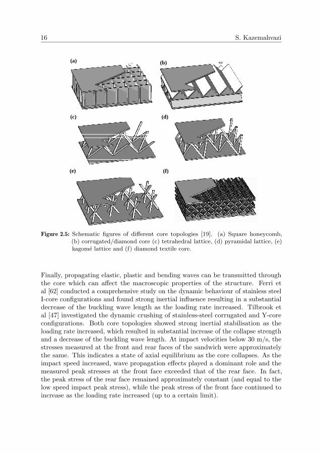
During the past decade there has been an effort to develop novel core topologiesthat have good performance compared to traditional foam cores [18–20]. The coretopologies can be divided into two main categories: prismatic cores and lattice trusscores, see figure 2.5. Examples of prismatic cores are square honeycombs [21,22],corrugated cores and diamond configuration cores [23–25]. Lattice truss corestypically consist of pyramidal, tetrahedral, kagome or textile configurations [26–30].The core members of these periodic core configurations are primarily subjected toaxial loading, and thus the predominant mode of failure of the core members isbuckling. Buckling dominated failure is especially seen in core configurations with alow relative density, i.e. when the core members are slender. In order to increase theresistance to buckling without adding substantial weight, variants of tubular latticetruss cores [31–33] and hierarchical core concepts [24,34,35] have been developed and

Introduction 15
v0, I
Stage I(Fluid structure interaction)
Stage II
Core
Face sheets
Stage II(Core crushing)
Stage III(bending & stretching)
Figure 2.4: Schematic picture of sandwich structure subject to a blast scenario
show significant increase in strength compared to its monolithic counterpart. Figure2.6 summarises the experimental quasi-static compressive strengths for a majorityof sandwich core materials available in the literature today. It is seen that coreconcepts made out of carbon fibre reinforced plastics (CFRP) have the best strengthperformance for the entire density range. At low core densities CFRP pyramidallattice truss cores outperform all other core configurations. The CFRP squarehoneycomb cores and the corrugated hierarchical cores have the best performancein the intermediate density range, whereas the monolithic corrugated CFRP coreshow highest strength for densities above 110kgm−3.
In addition to good quasi-static performance, sandwich structures that are usedin military vehicles or naval ships need to have good resistance to blast and ballisticloading conditions, as discussed previously. Several studies have investigated thebehaviour of prismatic and lattice truss cores when subjected to ballistics [55,56] andblast loading [17,47,57–61]. Most studies report an increase in blast performancefor sandwich configurations compared to monolithic structures. Square honeycombscores shows the best out-of-plane performance, corrugated and diamond cores havehigh longitudinal stretching performance and lattice trusses have competitive per-formance at low core densities.
Dynamic loading scenarios of the aforementioned periodic cellular cores differfrom the quasi-static loading case in three fundamental ways that will affect theload response. First, the constituent material of the structure may show strain ratedependence. Second, since the cellular cores are buckling dominated, inertial effectscan delay the onset of buckling and/or change the wave length of the buckling mode.
16 S. Kazemahvazi
(a)
(c)
(b)
(d)
(e) (f)
Figure 2.5: Schematic figures of different core topologies [19]. (a) Square honeycomb,(b) corrugated/diamond core (c) tetrahedral lattice, (d) pyramidal lattice, (e)kagome lattice and (f) diamond textile core.
Finally, propagating elastic, plastic and bending waves can be transmitted throughthe core which can affect the macroscopic properties of the structure. Ferri etal [62] conducted a comprehensive study on the dynamic behaviour of stainless steelI-core configurations and found strong inertial influence resulting in a substantialdecrease of the buckling wave length as the loading rate increased. Tilbrook etal [47] investigated the dynamic crushing of stainless-steel corrugated and Y-coreconfigurations. Both core topologies showed strong inertial stabilisation as theloading rate increased, which resulted in substantial increase of the collapse strengthand a decrease of the buckling wave length. At impact velocities below 30 m/s, thestresses measured at the front and rear faces of the sandwich were approximatelythe same. This indicates a state of axial equilibrium as the core collapses. As theimpact speed increased, wave propagation effects played a dominant role and themeasured peak stresses at the front face exceeded that of the rear face. In fact,the peak stress of the rear face remained approximately constant (and equal to thelow speed impact peak stress), while the peak stress of the front face continued toincrease as the loading rate increased (up to a certain limit).

Introduction 17
Monolithic CFRP corrugationHierarchical CFRP corrugation
Pyramidal CFRP lattice truss
CFRP square honeycomb
Figure 2.6: Experimentally measured out-of-plane compression strength of different sand-wich core concepts. [22–25,30,32,35–44,44,45,45–54]
Although the dynamic response of metallic lattice truss and prismatic coreshave been thoroughly explored, there has been little research done on the fibrecomposite counterpart. In this research the out-of-plane impact behaviour of aprismatic composite core was explored with a potential future application as ahigh performance and multifunctional core in naval ship hulls. Experiments wereperformed at quasi-static loading rate, low and high speed impacts. The low- andintermediate speed impacts resembles a loading scenario of a ship collision andhull slamming loads, while the high speed impacts simulate blast loading scenarios.Especially the effects of inertial stabilisation were studied and its effect on theout-of-plane compressive strength of the core.


3 Ethics in Military Research
Each year billions of dollars are invested in military research which is conducted atUniversities and in private organisations. How does this research benefit civiliansand in what way does it develop humanity? Who will use the research results and,maybe more important, how will it be used? These are questions I asked myselfbefore embarking upon my PhD-project. I believe that all science can do good aswell as bad, and maybe the thing that will distinguish the good from the bad is theapplication that the end user of the research chooses.
The research done within this thesis is funded by military organisations withprimary applications in military structures. The main purpose of this research isto improve the blast and impact protection properties of military structures. It isimportant to elucidate the fact that the research focuses on protective structures,i.e. research with the objective of saving lives, and not weapons (which typicallyhave the objective of eliminating life).
Although a lot of research is primarily intended for military use, history hasgiven many great civilian spin-offs from military research. One example of suchspin-off is the Internet (Arpanet) which started as an American military researchproject. The global positioning system (GPS) was originally also developed bythe US Department of Defence. The primary purpose was to use it as a deliverysystem for high precision weapons (missiles). Today the GPS is available for civilapplications and contributes in to saving many lives around the world. Anotherexample is the modern radar and spin-off products from the radar research.
During the World War II a company named Raytheon Corporation got a contractfrom the American Military to perfect and mass-produce the magnetron (a gadgetthat produces microwaves) for ground-based, airborne and shipborne military radarsystems. While perfecting the magnetron, the scientist Dr Percy Spencer noticedsomething very unusual. As he tested the magnetron he discovered that the candybar in his pocket started to melt. This incident intrigued him and he started toexperiment with other food objects and soon he had designed a metal box whichwas fed by microwaves - the first microwave oven. By late 1946, Raytheon had fileda patent proposing that microwaves could be used to cook food. Although thisspin off invention did not save the world, it sure made life easier for a lot of peopleand the invention serves as a good example of where a military funded project canresults in something good for civilians.
19


4 Objectives
The main objective of this thesis has been to improve the structural performance ofhigh speed naval ship hulls. This has been done considering both the dynamic loadconditions (such as blast and ballistic impact) and by improving the quasi-staticperformance using novel sandwich cores.
More specifically the objectives have been:
� Develop tools for predicting the residual strength of composite panels withmultiple damages.
� Investigate the high rate loading behaviour of composite structures and specif-ically how it affects the notch sensitivity of the structure
� Enhance the quasi-static and the blast performance of sandwich structuresusing novel core topologies
21


5 Summary of appended papers
Low weight is one of the most important factors in the design process of high speednaval ship hulls. Lower structural weight enables the possibility of down-sizing thepropulsion system of the ship and thus decrease manufacturing and operating costsas well as reducing the in-service energy consumption.
Two efficient ways of reducing the structural weight of a ship is by using highperformance composite materials and by using geometrically efficient structures,such as the sandwich concept. The Visby Class Corvette, figure 5.1 is one example ofan all-composite sandwich naval ship. In addition to low weight, the Visby Corvettehull is non-magnetic, has good surface flatness and good thermal insulation, whichlowers the radar and infrared signatures.
Figure 5.1: Visby class corvette with a sandwich structure hull consisting of carbon fibrereinforced vinyl-ester face sheets and PVC foam core (in courtesy of Kockums)
Naval ship hulls also need to have good dynamic loading protection. Example ofdynamic loading events are air and water blasts, ballistic impacts, hull slamming
23

24 S. Kazemahvazi
etc. In this thesis important aspects of dynamic loading of composite and sandwichstructures are addressed and presented in the appended papers as follows.
5.1 Paper A
The main objective with this paper was to investigate the notch sensitivity ofnon-crimp fabric glass fibre composites. The notch sensitivity was investigated forseveral different laminate configurations at varying tensile loading rate. Notcheswere created in the form of drilled circular holes as well as perforation damages fromfragment simulating projectile impacts.
It was shown that the non-crimp fabrics have very low notch sensitivity, especiallyfor laminate configurations with a large amount of fibres in the load direction.Further, the notch sensitivity was shown to be fairly constant with increasingloading rates (up to 100/s). For laminates with a large amount of fibres in theloading direction, very small difference in residual net-section strength was observedbetween laminates with drilled circular holes and laminates with holes generatedfrom fragment simulating projectile impacts.
5.2 Paper B
In this paper a heuristic approach was made in order to create an analytical modelto predict the residual strength of composite laminates with multiple randomlydistributed holes. The basis for this model was a comprehensive experimentalprogramme. It was found that unidirectional laminates with holes predominantlyfail through three failure modes: global net-section failure, local net-section failureand local shear failure. Each failure mode could be described by a physical geometricconstant which was used to create the analytical model. It was shown that thedeveloped model can predict the residual strength of unidirectional laminates withmultiple, randomly distributed holes with good accuracy.
5.3 Paper C and paper D
In paper C and paper D, novel prismatic high performance all-composite sandwichcores were developed. In paper C an analytical model was developed to predict thestrength and stiffness properties of the suggested cores. The model was compared tofinite element simulations and showed very good accuracy. In paper D the prismaticcores were manufactured and tested in shear loading and out-of-plane compressionloading. Further, the analytical model was used to create failure mechanism mapsand map out the overall behaviour of the different core configurations.
The novel cores show very high specific strength and stiffness and are potentialcandidates as core in high performance naval ship hulls.

Introduction 25
5.4 Paper E
Within this paper the dynamic properties of the prismatic cores, that were developedin paper C and paper D, were investigated. The dynamic out-of-plane strength ofan unit cell was tested experimentally in a gas gun - Kolsky bar set-up. Especially,different failure mechanisms and their effect on the structural strength was inves-tigated. It was found that cores with low relative density (slender core members)show very large inertial stabilisation effects and have a dynamic strength that canbe more than seven times higher than the quasi-static strength. Cores with higherrelative density show less increase in dynamic strength. The main reason for thedynamic strengthening is due to the strain rate sensitivity of the parent materialrather than inertial stabilisation of the core members. It was also shown that athigh loading rates (∼ 3000/s) the failure of the core switches into a progressive fibrecrushing mode rather than dynamic buckling and dynamic micro-buckling.


Bibliography
[1] M. Kaufmann. Cost Optimization of Aircraft Structures. Doctoral Thesis, KTH, 2009.
[2] I. Stenius. Hydroelaasticity in Marine Hull Bottom Panels - Modeling and Characteri-zation. Doctoral Thesis, KTH, 2009.
[3] SIKA Institute, SIKA Statistik 2007:19, RES 2005-2006, Den nationella resvaneunder-sokningen.
[4] J.Y. Wong. Theory of Ground Vehicles. Wiley, New York, third edition, 2001.
[5] M. F. Ashby and Y. J. M. Brechet. Designing hybrid materials. Acta Materialia,51:5801–5821, 2003.
[6] R.S. Thomson S. Georgiadis, A.J. Gunnion and B.K. Cartwright. Bird-strike simulationfor certification of the boeing 787 composite moveable trailing edge. CompositeStructures, 86:258–268, 2008.
[7] R. Vignjevic M. Meo, A.J. Morris and G. Marengo. Numerical simulation of low-velocity impact on an aircraft sandwich panel. Composite Structures, 62:353–360,2003.
[8] I. Smojver and D. Ivancevic. Numerical simulation of birde strike damage predictionin airplane flap structure. Composite Structures, 92:2016–2026, 2010.
[9] L. Olovsson A.G. Hanssen, Y. Girard, T. Berstad, and M. Lanseth. A numericalmodel for bird strike of aluminium foam-based sandwich panels. International Journalof Impact Engineering, 32:1127–1144, 2006.
[10] R. Rajendran and J. M. Lee. Blast loaded plates. Marine Structures, 22:99–127, 2009.
[11] A. Gupta T. Ngo, P. Mendis and J. Ramsay. Blast loading and blast effects onstructures - an overview. Electronic Journal of Structural Engineering, Special Issue:Loading on Structures:76–91, 2007.
[12] F. Zhu and G. Lu. A review of blast and impact of metallic and sandwichs structures.Electronic Journal of Structural Engineering, Special Issue: Loading on Structures:92–101, 2007.
[13] M. H. Keshavar and H. R. Pouretedal. An empirical method for predicting detonationpressure of chnofcl explosives. Thermochimica Acta, 414:203–208, 2004.
[14] U. Nystrom and Kent Gylltoft. Numerical studies of the combined effects of blast andfragment loading. International Journal of Impact Engineering, 36:995–1005, 2009.
27

28 S. Kazemahvazi
[15] L. Agardh and L. Laine. 3d fe-simulation of high-velocity fragment perforation ofreinforced concrete slabs. International Journal of Impact Engineering, 22:911–922,1999.
[16] J. Leppanen. Experiments and numerical analses of blast and fragment impacts onconcrete. International Journal of Impact Engineering, 31:843–860, 2005.
[17] N.A. Fleck and V.S. Deshpande. The resistance of clamped sandwich beams to shockloading. Journal of applied mechanics, 71:1–16, 2004.
[18] N.A. Fleck H.N.G. Wadley and A.G. Evans. Fabrication and structural performanceof periodic cellular metal sandwich structures. Composite Science and Technology,63:2331–2343, 2003.
[19] H.N.G. Wadley. Multifunctional periodic cellular metals. Philosophical Transactionsof the Royal Society A, 364:31–68, 2006.
[20] V. S. Deshpande, M. F. Ashby, and N. A. Fleck. Effective properties of the octet-trusslattice material. Journal of the Mechanics and Physics of Solids, 49(8):1747–1769,August 2001.
[21] F. Cote, V.S. Deshpande, N. A. Fleck, and A. G. Evans. The out-of-plane compressivebehavior of metallic honeycombs. Materials Science and Engineering A, 380:272–280,2004.
[22] B. P. Russell, V. S. Deshpande, and H. N. G. Wadley. Quasistatic deformation andfailure modes of composite square honeycombs. Journal of Mechanics of Materialsand Structures, 3(7):1315–1340, September 2008.
[23] S. Kazemahvazi and D. Zenkert. Corrugated all-composite sandwich structures. part1: Modeling. Composite Sciences and Technology, 69(7-8):913–919, June 2009.
[24] S. Kazemahvazi, D. Tanner, and D. Zenkert. Corrugated all-composite sandwichstructures. part 2: Failure mechanisms and experimental programme. CompositeSciences and Technology, 69(7-8):920–925, June 2009.
[25] F. Cote, V.S. Deshpande, N. A. Fleck, and A. G. Evans. The compressive and shearresponses of corrugated and diamond lattice materials. International Journal of Solidsand Structures, 43:6220–6242, 2006.
[26] V.S. Deshpande G.W. Kooistra and H.N.G. Wadley. Compressive behaviour of agehardenable tetrahedral lattice truss structures made from aluminium. Acta Materialia,52:4229–4237, 2004.
[27] G.W. Kooistra and H.N.G. Wadley. Lattice truss structures from expanded metalsheet. Material and Design, 28:507–514, 2007.
[28] R. Biagi and H. Bart-Smith. Imperfection sensitivity of pyramidal core sandwichstructures. International Journal of Solids and Structures, 44:4690–4706, 2007.
[29] S. Torquato S. Hyun, A.M. Karlsson and A.G. Evans. Simulated properties of kagomeand tetragonal truss core panels. International Journal of Solids and Structures,40:6989–6998, 2003.
Introduction 29
[30] H. N. G. Wadley K. Finnegan, G. Kooistra and V. S. Deshpande. The compressiveresponse of carbon fiber composite pyramical truss sandwich cores. InternationalJournal of Material Research, 98:1–9, 2007.
[31] D.T. Queheillalt and H.N.G. Wadley. Pyramidal lattice truss structures wih hollowtrusses. Material Science and Engineering A, 397:132–137, 2005.
[32] H. J. Rathbun, F. W. Zok, S. A. Waltner, C. Mercer, A. G. Evans, D. T. Queheillalt,and H. N. G. Wadley. Structural performance of metallic sandwich beams with hollowtruss cores. Acta Materialia, 54(20):5509–5518, December 2006.
[33] B.-K. Lee and K.-J. Kang. Compressive strength of tube-woven kagome truss cores.Scripta Materialia, 6(6):391–394, March 2009.
[34] G.W. Kooistra, V.S. Deshpande, and H.N.G. Wadley. Hierarchical corrugated coresandwich panel concepts. Journal of Applied Mechanics, 74:259–268, 2007.
[35] F. Cote, B. P. Russell, V.S. Deshpande, and N. A. Fleck. The through-thickness com-pressive strength of a composite sandwich panel with a hierarchical square honeycombsandwich core. Journal of Applied Mechanics, 76:061004.1–061004.8, November 2009.
[36] Evonik Rohm GmbH. Data Sheet: Rohacell IG/IG-F, [www.rohacell.com]. 11 August2009.
[37] Evonik Rohm GmbH. Data Sheet: Rohacell WF, [www.rohacell.com]. 11 August 2009.
[38] DIAB. Data Sheet: Divinycell HP, [www.diabgroup.com]. 01 November 2009.
[39] DIAB. Data Sheet: ProBalsa, [www.diabgroup.com]. 11 December 2009.
[40] S. Heimbs, P. Middendorf, S. Kilchert, A. F. Johnson, and M. Maier. Experimental andnumerical analysis of composite folded sandwich core structures under compression.Applied Composite Materials, 14:363–377, 2007.
[41] S. Heimbs, J. Cichosz, M. Klaus, S. Kilchert, and A. F. Johnson. Sandwich structureswith textile-reinforced composite foldcores under impact loads. Composite Structures,page in press, 2009.
[42] S. Lee, F. Barthelat, J. W. Hutchinson, and H. D. Espinosa. Dynamic failure ofmetallic pyramidal truss core materials - experiments and modeling. InternationalJournal of Plasticity, 22(11):2118–2145, November 2006.
[43] F. W. Zok, S. A. Waltner, Z. Wei, H. J. Rathbun, R. M. McMeeking, and A. G. Evans.A protocol for chracterizing the structural performance of metallic sandwich panels:application to pyramidal truss cores. International Journal of Solids and Structures,41(22-23):6249–6271, November 2004.
[44] J.-H. Lim and K.-J. Kang. Mechanical behavior of sandwich panels with tetrahedraland kagome truss cores fabricated from wires. International Journal of Solids andStructures, 43(17):5228–5246, August 2006.
[45] J. Wang, A. G. Evans, K. Dharmasena, and H. N. G. Wadley. On the performanceof truss panels with kagome cores. International Journal of Solids and Structures,40(25):6981–6988, December 2003.

30 S. Kazemahvazi
[46] Y.-H.Lee, B.-K. Lee, I. Jeon, and K.-J. Kang. Wire-woven bilk kagome truss cores.Acta Materialia, 55(18):6084–6094, October 2007.
[47] M. T. Tilbrook, D. D. Radford, V. S. Deshpande, and N. A. Fleck. Dynamic crushingof sandwich panels with prismatic lattice cores. International Journal of Solids andStructures, 44(18-19):6101–6123, September 2007.
[48] M. Zupan, V. S. Deshpande, and N. A. Fleck. The out-of-plane compressive behaviourof woven-core sandwich plates. European Journal of Mechanics - A / Solids, 23(37):411–421, May-June 2004.
[49] Plascore Incorporated. Data Sheet: PAMG-XR1 5056 Aluminium Honeycomb,[www.plascore.com]. 01 November 2009.
[50] Plascore Incorporated. Data Sheet: PN1 Commercial Grade Aramid Fiber Honeycomb,[www.plascore.com]. 01 November 2009.
[51] E. Koza, M. Leonowicz, S. Wojciecjowski, and F. Simancik. Compressive strength ofaluminium foams. Materials Letters, 58:132–135, 2003.
[52] K. Y. G. McCullough, N. A. Fleck, and M. F. Ashby. Uniaxial stress-strain behaviorof aluminium alloy foams. Acta Materialia, 47(8):2323–2330, 1999.
[53] M. Zupan, C. Chen, and N. A. Fleck. The plastic collapse and energy absorptioncapacity of egg-box panels. International Journal of Mechanical Sciences, 45(5):851–871, May 2003.
[54] M. Kintscher, L. Karger, A. Wetzel, and D. Hartung. Stiffness and failure behaviour offolded sandwich cores under combined transverse shear and compression. Composites:Part A, 38:1288–1295, 2007.
[55] D.D. Radford C.J. Yungwirth, M. Aronsson, and H.N.G. Wadley. Experimentalassessment of the ballistic response of composite pyramidal lattice truss structures.Composites Part B: Engineering, 39:556–569, 2007.
[56] J.H. O´Connor C.J. Yungwirth, H.N.G. Wadley, A.J. Zakraysek, and V.S. Deshpande.Impact response of sandwich plates with a pyramidal lattice core. International journalof impact engineering, 35:920–936, 2007.
[57] D.D. Radford H.J. Rathbun, M.Y. He Z. Xue, J. Yang, N.A. Fleck V.S. Deshpande,J.W. Hutchinson, F.W. Zok, and A.G. Evans. Performance of metallic honeycomb-coresandwich beams under shock loading. International journal of solids and structures,43:1746–1763, 2006.
[58] V.S. Deshpande V. Rubino and N.A. Fleck. The dynamic response of clampedrectangular y-frame and corrugated core. European Journal of Mechanics, 28:14–24,2009.
[59] V.S. Deshpande V. Rubino and N.A. Fleck. The dynamic response of end-clampedsandwich beams with a y-frame or corrugated core. International journal of impactengineering, 35:829–944, 2008.
[60] V.S. Deshpande D.D. Radford, G.J. McShane and N.A. Fleck. Dynamic compressiveresponse of stainless-stell square honeycombs. Journal of applied mechanics, 74:658–667, 2007.

Introduction 31
[61] H.N.G. Wadley K.P. Dharmasena, D.T. Queheillalt, P. Dudt, D. Knight Y. Chen, A.G.Evans, and V.S. Deshpande. Dynamic compression of metallic sandwich structuresduring planar impulsive loading in water. European Journal of Mechanics, 29:56–67,2010.
[62] E. Ferri, E. Antinucci, M. Y. He, J. W. Hutchinson, F. W. Zok, and A. G. Evans.Dynamic buckling of impulsively loaded prismatic cores. Journal of Mechanics ofMaterials and Structures, 1(8):1345–1365, 2006.


Division of work between authors
Paper A
Kazemahvazi planned and conducted the experimental programme and the followinganalysis. The paper was written by Kazemahvazi with support from Zenkert andBurman. Burman presented the paper at ICCM16, Kyoto (Japan).
Paper B
Kazemahvazi and Kiele performed the experiments. Kazemahvazi made the analysisand modelling. Kazemahvazi wrote the paper with support from Zenkert.
Paper C
Kazemahvazi made the analysis and modelling with support from Zenkert. Kazemah-vazi wrote the paper with support from Zenkert.
Paper D
Kazemahvazi and Tanner performed the experiments. Kazemahvazi made theanalysis and modelling. Kazemahvazi wrote the paper with support from Zenkert.
Paper E
Kazemahvazi manufactured the specimens. Kazemahvazi and Russell performedthe experiments. Kazemahvazi and Russell made the analysis with support fromDeshpande. Kazemahvazi wrote the paper with support from Zenkert, Russell andDeshpande.
33


Part II
Appended papers
35
