impact of fire on steel reinforcement in reinforced ... · pdf fileimpact of fire on steel...
TRANSCRIPT

International Journal of Scientific and Research Publications, Volume 5, Issue 10, October 2015 1 ISSN 2250-3153
www.ijsrp.org
IMPACT OF FIRE ON STEEL REINFORCEMENT IN
REINFORCED CONCRETE STRUCTURES
Yakudima Akibu Ghali*, Ruban Sugumar**, Hassan Abba Musa***
* Civil Engineering Department, Sharda University, Knowledge Park III, Greater Noida, UP – Delhi.
* * Department of Civil Engineering, Indian Institute of Technology (IIT) Delhi, Hauz Khas, New Delhi.
*** Civil Engineering Department, Sharda University, Knowledge Park III, Greater Noida, UP – Delhi.
Abstract: The behaviour of RC beam and column members at elevated temperatures are being studied experimentally and
analytically widely. However, hardly any attention is given towards analyzing the behaviour of structures with SFRC, e.g. SFRC
beams, columns, portal frame etc. exposed to fire. Herein, is a paper research to study the impact of fire on steel reinforcement in
reinforce concrete structures at elevated temperature that analyzed by means of a three dimensional (3D) nonlinear transient thermo-
mechanical finite element (FE) analysis and validated with commercially software ANSYS and SAFIR.
Key Words: SFRC, Fire, Steel, Concrete, ANSYS, SAFIR.
1.0 INTRODUCTION
Fire remains one of the serious potential risks to most buildings and structures. The extensive use of concrete as a structural material
has led to the need to fully understand the effect of fire on reinforces concrete structures. Fire has been a source of comfort and
catastrophe to the human race since ancient history. Fire is a destructive force causing thousands of deaths and loss of property worth
billions of dollars. Fire disasters can occur below the ground, on the ground or above the ground. Sometimes, they occur in the most
unexpected or unpredictable circumstances. Considerable progress has been made in the understanding of structural fire protection
since the earliest attempts to implement fire safety. Fire protection activity was initiated after a great fire in London in 1666; however
investigation of structural fire protection began in second half of 18th century. Further the advances in material technology led to the
concept of fire proof structures using gypsum. Later, Metropolitan Borough Act (1844) and London Building Act (1894) brought
refinement in building control regulations. A scientific approach to research into structural fire resistance began towards the end of
19th century after the establishment of British Fire Protection Committee (BFPC). In 1932 first British Standard (BS 476:1932)
related to fire was published which defined the test for fire resistance. The recent collapse of the twin-towers, World Trade Centre
building in New York, USA, due to the terrorist attack and subsequent fire has renewed the interest in fire-resistant design of
structures. Traditionally, the provision of fire resistance for reinforced concrete (RC) structures and components is usually treated
indirectly in structural design. Most design procedures assume sufficient fire resistance, if certain criteria, mainly the distance of the
reinforcing bars from the concrete surface, are kept. Building codes specify regulations for buildings designed in such a way that they
exhibit an acceptable level of performance in the event of fire. These regulations are concerned with the prevention of premature
collapse, the provision to evacuate the occupants from the structure on fire, avoiding spread of the fire to adjacent properties etc.
However, when the means for containing a fire fail, such as a Fire Suppression System, Structural Integrity is the last line of defense.
Hence, it is necessary to consider the risk of fire in designing of structures. Generally concrete is thought to have good fire resistance
but the behavior of reinforced concrete columns under high temperature is mainly affected by the strength of the concrete, the changes
of material property and explosive spalling. However, high temperatures affect the strength of the concrete by explosive spalling and
so affect the integrity of the concrete structure. In recent years, many researchers studied the fire behavior of concrete columns; their
studies included experimental and an analytical evaluation for reinforced concrete. Concrete is a material that has an excellent intrinsic
behavior when exposed to fire, it does not burn, (non-combustible), and it has a high thermal massively, which significantly slows
down the spread of heat through concrete elements. As a matter of fact, in most common fires only the outer layer of the concrete with
a thickness of approximately 3 to 5 cm is damaged (Denoël, 2007). Therefore, many concrete buildings that experienced fire can be
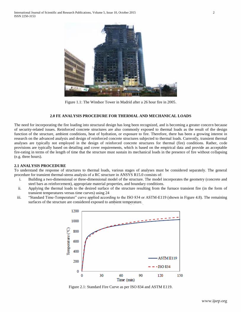
fairly simply restored and reused. An excellent example of the good behavior towards fire of concrete structures is the Windsor Tower
in Madrid (Denoël, 2007). The fire occurred on 14 February 2005, during which the building was fortunately unoccupied. Despite that
the fire spread over numerous floors and lasted for 26 hours, the building remained standing, as can be seen in Figure 1.1, only the part
that collapsed were the steel perimeter columns above the 20th floor, which supported the floors.
International Journal of Scientific and Research Publications, Volume 5, Issue 10, October 2015 2
ISSN 2250-3153
www.ijsrp.org
Figure 1.1: The Windsor Tower in Madrid after a 26 hour fire in 2005.
2.0 FE ANALYSIS PROCEDURE FOR THERMAL AND MECHANICAL LOADS
The need for incorporating the fire loading into structural design has long been recognized, and is becoming a greater concern because
of security-related issues. Reinforced concrete structures are also commonly exposed to thermal loads as the result of the design
function of the structure, ambient conditions, heat of hydration, or exposure to fire. Therefore, there has been a growing interest in
research on the advanced analysis and design of reinforced concrete structures subjected to thermal loads. Currently, transient thermal
analyses are typically not employed in the design of reinforced concrete structures for thermal (fire) conditions. Rather, code
provisions are typically based on detailing and cover requirements, which is based on the empirical data and provide an acceptable
fire-rating in terms of the length of time that the structure must sustain its mechanical loads in the presence of fire without collapsing
(e.g. three hours).
2.1 ANALYSIS PROCEDURE To understand the response of structures to thermal loads, various stages of analyses must be considered separately. The general
procedure for transient thermal-stress analysis of a RC structure in ANSYS R15.0 consists of:
i. Building a two-dimensional or three-dimensional model of the structure. The model incorporates the geometry (concrete and
steel bars as reinforcement), appropriate material properties, and boundary conditions.
ii. Applying the thermal loads to the desired surface of the structure resulting from the furnace transient fire (in the form of
transient temperatures versus time curves) using 24
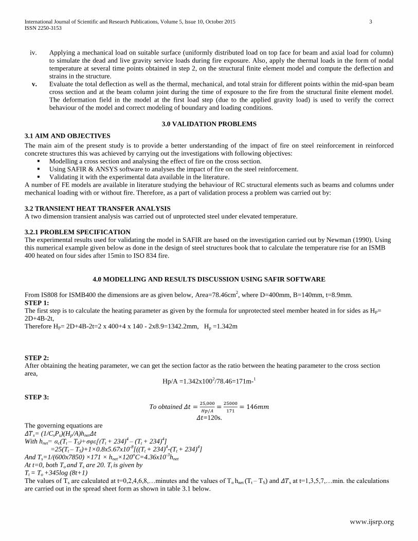
iii. “Standard Time-Temperature” curve applied according to the ISO 834 or ASTM-E119 (shown in Figure 4.8). The remaining
surfaces of the structure are considered exposed to ambient temperature.
Figure 2.1: Standard Fire Curve as per ISO 834 and ASTM E119.
International Journal of Scientific and Research Publications, Volume 5, Issue 10, October 2015 3
ISSN 2250-3153
www.ijsrp.org
iv. Applying a mechanical load on suitable surface (uniformly distributed load on top face for beam and axial load for column)
to simulate the dead and live gravity service loads during fire exposure. Also, apply the thermal loads in the form of nodal
temperature at several time points obtained in step 2, on the structural finite element model and compute the deflection and
strains in the structure.
v. Evaluate the total deflection as well as the thermal, mechanical, and total strain for different points within the mid-span beam
cross section and at the beam column joint during the time of exposure to the fire from the structural finite element model.
The deformation field in the model at the first load step (due to the applied gravity load) is used to verify the correct
behaviour of the model and correct modeling of boundary and loading conditions.
3.0 VALIDATION PROBLEMS
3.1 AIM AND OBJECTIVES
The main aim of the present study is to provide a better understanding of the impact of fire on steel reinforcement in reinforced
concrete structures this was achieved by carrying out the investigations with following objectives:
Modelling a cross section and analysing the effect of fire on the cross section.
Using SAFIR & ANSYS software to analyses the impact of fire on the steel reinforcement.
Validating it with the experimental data available in the literature.
A number of FE models are available in literature studying the behaviour of RC structural elements such as beams and columns under
mechanical loading with or without fire. Therefore, as a part of validation process a problem was carried out by:
3.2 TRANSIENT HEAT TRANSFER ANALYSIS A two dimension transient analysis was carried out of unprotected steel under elevated temperature.
3.2.1 PROBLEM SPECIFICATION
The experimental results used for validating the model in SAFIR are based on the investigation carried out by Newman (1990). Using
this numerical example given below as done in the design of steel structures book that to calculate the temperature rise for an ISMB
400 heated on four sides after 15min to ISO 834 fire.
4.0 MODELLING AND RESULTS DISCUSSION USING SAFIR SOFTWARE
From IS808 for ISMB400 the dimensions are as given below, Area=78.46cm2, where D=400mm, B=140mm, t=8.9mm.
STEP 1:
The first step is to calculate the heating parameter as given by the formula for unprotected steel member heated in for sides as HP=
2D+4B-2t,
Therefore HP= 2D+4B-2t=2 x 400+4 x 140 - 2x8.9=1342.2mm, Hp =1.342m
STEP 2:
After obtaining the heating parameter, we can get the section factor as the ratio between the heating parameter to the cross section
area,
Hp/A =1.342x1002/78.46=171m-
1
STEP 3:
To obtained 𝛥𝑡 =25,000
𝐻𝑝/𝐴=
25000
171= 146𝑚𝑚
𝛥𝑡=120s.
The governing equations are
𝛥𝑇s= (1/CsPs)(Hp/A)hnet𝛥𝑡 With hnet= αc(Tt – TS)+σφε[(Tt + 234)
4 – (Tt + 234)
4]
=25(Tt – TS)+1×0.8x5.67x10-8
[((Tt + 234)4-(Tt + 234)
4]
And Ts=1/(600x7850) ×171 × hnet×120oC=4.36x10
-3hnet
At t=0, both To and Ts are 20. Tt is given by
Tt = To +345log (8t+1)
The values of Ts are calculated at t=0,2,4,6,8,…minutes and the values of To hnet (Tt – TS) and 𝛥𝑇s at t=1,3,5,7,…min. the calculations
are carried out in the spread sheet form as shown in table 3.1 below.

International Journal of Scientific and Research Publications, Volume 5, Issue 10, October 2015 4
ISSN 2250-3153
www.ijsrp.org
Table 4.1: Temperature Rise in an Unprotected Steel Section
t(min) Ts(oC) h 𝛥𝑇s(
oC) 𝑇s(
oC)
0 20
349.2 14693 64
2
502.3 26110 113.8 84
4
576.4 30847 113.5 332.3
6
625.8 30850 134.5 466.8
8
662.8 26099 113.8 466.8
10
692.5 18132 79.1 580.6
12
717.3 10843 47.3 659.6
14
738.6 6473 28.2 671
16 672
Taking the mean of values 14 and 16min, the steel has reached a temperature of 671.5oc after 15 min.
Figure 4.1: Newman (1990) Temperature-time curve for steel reinforcement (ISMB400).
4.1 MODELING USING SAFIR
Similarly this calculation was done using SAFIR software in other to calculate the amount of temperature
exacted on the steel reinforcement as done by Newman (1990) structures. The steps are as follows:
STEPS OF CALCULATING TEMPERATURE USING SAFIR SOFTWARE
First Step: Using WIZARD2007 to obtain the input file for SAFIR.
i. Click on from desktop wizard2007
ii. A dialogue box opened select user, input the height of section as (D) 400, input , input thickness of the web as 8.9mm also
input the Root fillet if any and click on concrete slab if you want to add concrete slab to your problem. And click on next -
0
100
200
300
400
500
600
700
800
0 5 10 15 20
Tem
pe
ratu
re 0
c
Time (Minutes)

International Journal of Scientific and Research Publications, Volume 5, Issue 10, October 2015 5
ISSN 2250-3153
www.ijsrp.org
Figure 4.2: Wizard 2007 input data dialog box.
iii. Select the protection material and the protection thickness. If any, but in this case protection layer select (None) and click on
next -
iv. Select the number of elements to describe the steel profile, that is the meshing and click on next -
Figure 4.3 mesh configuration.
v. Select the fire curve as FISO and the rotation angle if any, and so also the exposed faces of the steel profile,
Face1,face2,face3,fac4 and press on next -
vi. Select the number of integration points on elements and global coordinates of the node line and the centre of torsion.
Precision as -4,number of integration points as 3 , time step as 12sec, end time 2400, time print 60sec, and press on next -
Figure 4.4: Wizard 2007 faces in contact with fire dialog box

International Journal of Scientific and Research Publications, Volume 5, Issue 10, October 2015 6
ISSN 2250-3153
www.ijsrp.org
vii. The wizard has finished collecting the information needed for the SAFIR input file, and press Finish to save values in the
data file as abba.
Figure 4.5: Wizard 2007 input data final dialog box.
Second Step: Using SAFIR software to run the inputed data from WIZARD2007 software
i. Go to C: / click on SAFIR.
ii. A dialogue box opened input the file name as abba and click enter to run the data for the out file to be used in DIAMOND
software.
Figure 4.6: SAFIR processing data dialog box.
Third Step: Using DIAMOND software obtain the temperatures as well as the charts
1. Click on DIAMOND 2011 from the desktop
2. Click on file menu and select open from there select the output file created from SAFIR as abba.
3.The file will opened from there click on result and select temperature, the result for temperature will be displayed, also by clicking
on result by selecting chart the chart is going to be plotted.

International Journal of Scientific and Research Publications, Volume 5, Issue 10, October 2015 7
ISSN 2250-3153
www.ijsrp.org
Figure 4.7 Diamond output chat file.
The image above shows the screen snap from the DIAMOND environment, representing the temperatures at the time of 900sec
(15minutes). Similarly the chart for that is as shown below.
Figure 4.8: Temperature-time curve for steel reinforcement Model (SAFIR v2011a3)
It can be seen that the value of temperature obtained as the time of 15min (900sec) from Fig.4.1 the manual calculation (Newman
1990) the steel has reached a temperature of 671.5oC after 15 min. while from Fig. 4.8 the DIAMOND Output file the steel reached
671.4oC at 900sec (15min). Almost about 0.5
oc is the difference between the two. Thus, it is clear to say that the predicted and
experimental values are in good agreement with each other.
4.2 HEAT TRANSFER ANALYSIS Three Dimensional (3D) Transient heat transfer analysis of a concrete beam reinforced with glass fiber reinforced polymer (GFRP)
rebar is carried out.
4.2.1 PROBLEM SPECIFICATION Here, a 3D heat transfer analysis on RC beam reinforced with GFRP rebars is carried out using ANSYS 15.0. The experimental results
used for validating the model in ANSYS are based on the investigation carried out by Pratik (2013). A FE model for the same was
also developed by Abbasi and Hogg, (2006). The beam is subjected to fire, at its bottom and on the sides, simulated by using standard
fire curve as per ISO 834. The beam is 4400 mm long with cross section dimensions of 350 by 400 mm reinforced with 12.7 mm
diameter 7 GFRP rebars in two layers at the bottom and 2 at the top; surrounded by 9 mm stirrups at 160 mm center to center arranged
as shown in Figure 4.9. The cover to the reinforcement is 75 mm at the bottom and 50 mm on the sides and at the top. The thermal
properties of the material useful for the analysis are provided in Table 4.2 below. The strength of concrete used is 42 MPa i.e. a
normal strength concrete.
Table 4.2: Thermal Properties of the Materials for Validation Problem

International Journal of Scientific and Research Publications, Volume 5, Issue 10, October 2015 8
ISSN 2250-3153
www.ijsrp.org
Material
Thermal conductivity (k) Wm/K
Density ( ρ)
kg/m3
Specific heat (C)
J/kgK
Concrete 2.7 X 10⁻³
2.32 X 10⁻⁶
722.8
Rebars 4.0 X 10⁻³
1.60 x 10⁻⁶
1310
Figure 4.9: Arrangement of GFRP Rebars in Concrete Beam (All Dimensions are in mm)
5.0 MODELLING, RESULTS AND DISCUSSION
The 3D beam Reinforced concrete was modelled using ANSYS 15.0 software. The concrete beam was modelled using SOLID 65
element, for heat transfer analyses. It has single degree of freedom at nodes i.e. temperature. The GFRP bars are modelled using
LINK180 element. This element also has single degree of freedom, temperature, at each node. As no mechanical load is applied, no
mechanical boundary conditions are applied to the model. Full bonding is assumed between the rebars and the concrete and this was
achieved in the software. The entire beam model was subjected to an ambient room temperature of 200C in the form of predefined
initial condition. Then, the beam is subjected to fire in the form of standard time temperature curve as per ISO 834 at the vertical faces
and the soffit of the beam. For this, temperature boundary condition is specified at the sides and soffit of the beam and varying with
amplitude of standard time temperature curve during the transient heat transfer. The temperature variations at different time intervals
obtained in this analysis using ANSYS at the centre and side of the beam are shown in Figures below 5.8 and 5.9.

International Journal of Scientific and Research Publications, Volume 5, Issue 10, October 2015 9
ISSN 2250-3153
www.ijsrp.org
Figure 5.1: Concrete beam layer FEM model.
Figure 5.2: GFRP layer FEM model.

International Journal of Scientific and Research Publications, Volume 5, Issue 10, October 2015 10
ISSN 2250-3153
www.ijsrp.org
Figure 5.3: GFRP and stirrups layer FEM model.
Figure 5.4: Mesh configuration of Beam with Rebars for problem.

International Journal of Scientific and Research Publications, Volume 5, Issue 10, October 2015 11
ISSN 2250-3153
www.ijsrp.org
Figure 5.5 Side view of the RC beam.
Figure 5.6 ISO 834 fire curve.

International Journal of Scientific and Research Publications, Volume 5, Issue 10, October 2015 12
ISSN 2250-3153
www.ijsrp.org
Figure 5.7: Nodal Solution for the FEM model at 130min.
Figure 5.8: Side view Temperature Variation in Beam Obtained in Present Study.
Figure 5.9: Temperature Variation in Beam (Pratik, 2013).

International Journal of Scientific and Research Publications, Volume 5, Issue 10, October 2015 13
ISSN 2250-3153
www.ijsrp.org
Figure 5.10: Temperature Variation in GFRP Obtained in this study
Figure 5.11: Temperature Variation in GFRP Obtained at the end of this simulation.
The time at which the temperature in GFRP bars reached 430
0C which was considered as the beginning of failure of GFRP bars was
around 90 minutes for the ANSYS model as shown in Figure 5.11 above, which is 3 minutes less than that of experimental value. It is
clear that the predicted and experimental values are in good agreement with each other. Although the FE model overestimates the
result as compared to the experimental data, this may be attributed to the lack of temperature dependent material properties of GFRP
rebars. Thus the developed FE model can be used as a valid numerical tool to predict the temperature distribution in concrete beams.
6.0 CONCLUSION AND RECOMMENDAATION
6.1 CONCLUSION
A nonlinear 3D FE model was developed in this study and validated against the experimental program conducted by Abbasi and Hogg
(Abbasi & Hogg, 2006) as can be seen in the previous sections. Good agreement between the measured experimental and predicted FE
simulation was obtained for the average temperature in the GFRP bars at all stages of fire exposure. Although the UK Building
Regulations (Building Regulations, 2000) for fire safety recommends the minimum periods of the fire resistance for the most
structural elements to be of 90 min, the fire tests and FE simulation results showed that concrete beams reinforced with GFRP bars can
achieve a fire endurance of about 130 minutes. Thus, using GFRP bars as concrete reinforcement seems to meet the fire design
requirements. Upon the validation of the measured data, the FE modeling could provide full field of results, in terms of 3D
temperature distribution.

International Journal of Scientific and Research Publications, Volume 5, Issue 10, October 2015 14
ISSN 2250-3153
www.ijsrp.org
It could be concluded that the developed FE model is a great tool to aid designers and researchers to predict numerically the
temperature distribution of RC beams reinforced with GFRP bars. Thus, the validated model could be used as a valid tool in lieu of
experimental testing especially in design oriented parametric studies.
6.2 RECOMMENDATION
Furthermore, the developed and verified FE model in this study could be used as a tool for further investigation of the fire
performance of RC beams reinforced with GFRP bars under different applied fire curves and boundary conditions. The FE modeling
can also be used to predict the deflection, ultimate load capacity and fire resistance time of the structural member with sufficient
accuracy. Modeling of shear stirrups in the structural member can be neglected for thermo-mechanical analysis.
In conclusion many cases, the design methods used in practice do not completely capture the true behaviour of steel reinforcement in
reinforced concrete structures on fire. A proper design should incorporate a design fire that is realistic and based upon physical
parameters and the structure must be studied as a whole, taking in account all the interactions between the elements. However, a lot of
work is still needed in order to incorporate these elements in a practical design tool.
7.0 ACKNOWLEDGMENT
The authors wish to acknowledge the staffs and management of Sharda University, India for their input and suggestions toward the
completion.
8.0 REFERENCES
[1]. Ali, F., Najdai, A., and Choi, S. (2010). “Numerical and Experimental Investigation of the Behavior of High Strength Concrete Columns in Fire.” Engineering
Structures, 32(5), 1236-1243.
[2]. Altun, F., Haktanir, T., and Ari, K. (2007). “Effects of Steel Fiber Addition on Mechanical Properties of Concrete and RC Beams.” Construction and Building Materials, 21(3), 654-661.
[3]. Arioz, O. (2007). “Effects of Elevated Temperatures on Properties of Concrete.” Fire Safety Journal, 42(8), 516-522.
[4]. Balaguru, N., and Shah, S. P. (1992). “Fiber Reinforced Cement Composites.” McGraw-Hill, New York [5]. Behbahani, H. P., Nematollahi, B., Sam, A. R. M., and Lai, F. C. (2012). “Flexural Behavior of Steel-Fiber-Added-RC (SFARC) Beams With C30 and C50 Classes
of Concrete.” International Journal of Sustainable Construction Engineering & Technology, 3(1), 54-64.
[6]. Brea W., Venkatesh K., Mark F. Green, and Luke B.(2008)”fire endurance of fiber-reinforced polymer strengthenedconcrete t-beams”,ACI Structural Journal. [7]. Lie, T. T., and Kodur, V. (1995). “Mechanical Properties of Fiber Reinforced Concrete at Elevated Temperatures.” Internal Report, Institute for Research in
Construction, National Research Council, Canada.
[8]. Colombo, M., Prisco, M. Di., and Felicetti, R. (2010). “Mechanical Properties of Steel Fiber Reinforced Concrete Exposed at High Temperatures.” Materials and Structures, 43(4), 475-491.
[9]. Chen, S. C., Lu, X. Z., Ren, A. Z., and Jiang, J. J. (2007). “Fiber Beam Element Model for the Collapse Simulation of Concrete Structures Under Fire.”
Proceedings of the International Symposium on Computational Mechanics, July 30th-August 1st, Beijing China . [10]. Chen Y.H ,ChangY.F , Yao G.C , Sheu M.S , Experimental research on postfirebehaviour of reinforced concrete columns, "Fire Safety Journal” 44 (2009)
741.748.
AUTHORS
First Author – Yakudima Akibu Ghali, M. Tech (Structure), Sharda University, UP – Delhi, [email protected]
Second Author – Ruban Sugumar, PhD (In view), Indian Institute of Technology (IIT) Delhi, [email protected]
Third Author – Hassan Abba Musa, M. Tech (Structure), Sharda University, UP – Delhi, [email protected]
Correspondence Author – Hassan Abba Musa, M. Tech (Structure), Sharda University, UP – Delhi, [email protected],
+919717974458.