impact of knowledge-based techniques on emerging ...€™ as novel applications in the radar...
TRANSCRIPT

RTO-EN-SET-063bis 7 - 1
Impact of Knowledge-Based Techniques on Emerging Technologies
H.D. Griffiths Head, Department of Electronic and Electrical Engineering
University College London Torrington Place, London WC1E 7JE
UK Tel: +44 20 7679 7310; fax: +44 20 7388 9325
email: [email protected]
SUMMARY This tutorial provides a discussion of the application of knowledge-based processing techniques to emerging technologies. Following the third of the tutorials in this series we interpret knowledge-based processing as the use of adaptivity and the exploitation of prior knowledge in such a way as to choose the optimum processing method in each case. We interpret ‘emerging technologies’ as novel applications, such as multifunction phased array radars, waveform diversity, bistatic and multistatic radars, and synthetic aperture radars. Firstly, we consider the potential of electronically-steered phased array antennas and the associated signal processing techniques. This is followed by a description of knowledge-based processing in the task scheduling in a multifunction phased array radar. It is shown that prior information on targets can be used to control parameters such as update rate and dwell time. Next, we consider waveform diversity, which may be considered to be a development of multifunction phased array radar, in which a radar may simultaneously radiate and receive different signals in different directions for different purposes. Such a scheme may entail adaptivity in the angular domain, in the time domain and in the coding domain (and conceivably in other domains as well), and the use of knowledge-based techniques in this processing has obvious attractions. Two examples are discussed: the first is target-matched illumination, which shows that there is an optimum waveform for the detection of a given target in a given environment, and the second is interpolation between two (or more) spectral bands to give the effect of a signal of very high bandwidth, and hence very high range resolution. Next there follows a discussion of the application of knowledge-based techniques to bistatic and multistatic radar, including the use of information on waveform properties in passive coherent location (PCL), tracking in multistatic radar, and ‘spatial denial’ as a waveform diversity technique to prevent the exploitation by an enemy of a radar as a bistatic illuminator. Finally, an example is given of the use of ‘context’ in target detection in synthetic aperture radar imagery, exploiting the fact that targets of interest will tend to be parked in groups close to hedges and the edges of woods rather than individually in the middle of open ground. Useful improvements in detection performance are obtained.
Keywords: radar, signal processing, adaptive arrays, multifunction phased array radar, resource management, waveform diversity, bistatic radar, synthetic aperture radar, knowledge-based systems.
1.0 INTRODUCTION This tutorial provides a discussion of the application of knowledge-based processing techniques to emerging technologies. Following the third of the tutorials in this series we interpret knowledge-based processing as the
Griffiths, H.D. (2006) Impact of Knowledge-Based Techniques on Emerging Technologies. In Knowledge-Based Radar Signal and Data Processing (pp. 7-1 – 7-28). Educational Notes RTO-EN-SET-063bis, Paper 7. Neuilly-sur-Seine, France: RTO. Available from: http://www.rto.nato.int/abstracts.asp.

Impact of Knowledge-Based Techniques on Emerging Technologies
7 - 2 RTO-EN-SET-063bis
use of adaptivity and the exploitation of prior knowledge in such a way as to choose the optimum processing method in each case. Knowledge-based systems form part of the subject of artificial intelligence, in which a knowledge base is used to guide an inference engine to make its processing decisions. We interpret ‘emerging technologies’ as novel applications in the radar domain, such as multifunction phased array radars, waveform diversity, and bistatic and multistatic radars, and synthetic aperture radars.
The first topic considered is the potential of electronically-steered phased array antennas and the associated signal processing techniques. These concepts are manifest in the multifunction phased array radar, in which electronic scanning may be employed both on transmit and receive, allowing adaptive control of waveform, PRF and dwell time, and performing a variety of surveillance and tracking tasks. Knowledge-based processing may be used to control the scheduling of tasks in such a radar, showing how prior information on targets can be used to ensure that the most critical tasks are performed first.
The next topic is waveform diversity, which may be considered to be a development of multifunction phased array radar, in which a radar may simultaneously radiate and receive different signals in different directions for different purposes (which may include communications or ECM as well as strictly radar). Such a scheme may entail adaptivity in the angular domain, in the time domain and in the coding domain (and conceivably in other domains as well), and the use of knowledge-based techniques in this processing has obvious attractions. Two examples are discussed: the first is target-matched illumination, which shows that there is an optimum waveform for the detection of a given target in a given environment, and the second is interpolation between two (or more) spectral bands to give the effect of a signal of very high bandwidth, and hence very high range resolution.
The third topic is the application of knowledge-based techniques to bistatic and multistatic radar, including the use of information on waveform properties in passive coherent location (PCL), tracking in multistatic radar, and ‘spatial denial’ as a waveform diversity technique to prevent the exploitation by an enemy of a radar as a bistatic illuminator.
Finally, an example is given of the use of ‘context’ in target detection in synthetic aperture radar imagery, exploiting the fact that targets of interest will tend to be parked in groups close to hedges and the edges of woods rather than individually in the middle of open ground. Useful improvements in detection performance are obtained.
2.0 MULTI-PHASED ARRAYS
The third lecture in this series has shown how antenna array signal processing techniques may be applied in radar, and particularly how these techniques are equivalent to those in the time / frequency domain. These properties and processing techniques include:
• Matched filtering;
• The effects of the sampling theorem (aliasing); in the angular domain aliasing results in grating lobes;
• Formation of a set of orthogonal filterbank responses by the Discrete Fourier Transform; in the angular domain the equivalent process is carried out by the Butler Matrix producing a set of orthogonal beams;
• Weighting to reduce sidelobes (at the expense of loss and of broadening of response); the same weighting functions (Taylor, Chebyshev, …) are usable;

Impact of Knowledge-Based Techniques on Emerging Technologies
RTO-EN-SET-063bis 7 - 3
• Synthesis of a desired radiation pattern (or spectrum) from a uniformly-spaced set of aperture (or time series) samples;
• Superresolution techniques; and
• Adaptive filtering.
The most useful of these properties, when used in the radar function, is undoubtedly the latter one, and the use of adaptive arrays and (particularly) STAP have already been described at some length.
One of the earliest array signal processing techniques is that of monopulse [14], which can give higher angular resolution than the classical Rayleigh limit, avoiding the echo fluctuations that would occur with more than one pulse. Other examples include multiplicative arrays and aperture synthesis [14]. Another example (on transmit) is the ‘crosseye’ jamming technique, which presents a wavefront with an abruptly-changing phase to deceive an incoming tracking radar.
The following section describes some more modern applications of antenna array signal processing, and in particular some to which knowledge-based approaches may be applied.
3.0 ELECTRONICALLY AGILE BEAM FORMING
The electronically-steered phased array is one of the key subsystems in a modern radar, and the properties and processing techniques referred to in the previous section are fundamental. The use of individual phased array modules (Figure 1) allow all of the advantages of reliability (‘graceful degradation’) and flexibility. Figure 2 shows the MESAR (Multifunction Electronically-Scanned Array Radar) testbed developed over the past twenty years of more as a testbed for many of the concepts of phased array radar.
antenna element
circulator or T/R switch
power amplifier
(multi-stage)
low noise amplifier
switch
phase shifter
array signal
distribution network
Figure 1: Block Diagram of a Typical Phased Array Module.
Figure 2: The MESAR (Multifunction Electronically Scanned Adaptive Radar) Active Phased Array Radar.
Even greater flexibility may be provided by direct digital synthesis of the signal at the array element. High-speed digital hardware is now sufficiently cheap that this can be straightforward. Such a digitally-generated signal can incorporate the phase shifts necessary to steer the beams, both in respect of the transmit signal and

Impact of Knowledge-Based Techniques on Emerging Technologies
7 - 4 RTO-EN-SET-063bis
the receiver local oscillator. The modulation on the transmitted signal may also be varied adaptively, to allow techniques such as target-matched illumination to be used.
Further, amplifier linearization techniques, such as the outphasing method due to Chireix [12] are being developed to allow multiple signals to be fed through a single power amplifier with minimal distortion and intermodulation, hence allowing a single aperture to be shared between radar, communications and other functions.
3.1 Knowledge-Based Techniques in Multifunction Phased Array Radars A multifunction radar is able to perform several different functions such as tracking, surveillance, missile guidance, kill assessment, all sharing the same antenna system. The greatest benefit of such a radar is its flexibility to undertake all these functions, changing the radar parameters such as waveform, frequency, pulse compression, dwell time and beam shaping, in order to cope well with all the different environments and operational scenarios. The functions consist of set of individual tasks that are competing for radar resources at any give instant. Because of this, the allocation of the radar resources must be executed efficiently by a resource manager to provide good performance of the overall system.
Two important processes must be done to allow adequate resource management. The first is the prioritization of the tasks that must be performed. The second is the scheduling that consists of forming a queue of tasks in a time line to be executed by the radar.
Some work has been done over the last years in order to design efficient scheduling algorithms. Casar-Corredera and Izquierdo-Fuente [31] proposed a scheduling process to interleave the tasks using a neural network. Strömberg and Grahn [45] developed two approaches for scheduling tracking and surveillance tasks. The first was based on operations research theory, and the other was based on temporal logic using artificial intelligence. Orman et al. [36] developed an algorithm using the concept of on-line coupled-task scheduling. The algorithm considers that between the pulse transmission time and the pulse reception time of a radar transmission, there is an idle time that could be used for interleaving new tasks. They suggested some heuristics to deal with this scheduling aspect. Another approach was developed by Stafford [44] and was based on the concept of timebalance. The functions to be performed by the radar should be divided into several tasks and jobs and a timebalance scheme was used to define which task or job should be scheduled next. The timebalance indicated how much time the radar owed to a function (surveillance, tracking etc). If a task was late, its time balance should be positive; if a task was due to be executed at a given time t, at t its timebalance should be zero; finally, if a task was early, its timebalance should be negative. Finally, Vine [48] proposed the use of fuzzy logic to introduce concepts such as dangerous and friendly in the scheduling process to resolve conflicts between tasks when the radar system is operating in an environment that leads to an overload situation.
All these approaches have in common the idea the tasks must have priorities associated to them and the decision-making will be done based on these priorities. The performance of the proposed schedulers is similar when the radar system is operating in a non-stressing situation and there are available radar resources to be allocated to functions. The difference between them becomes evident when the environment changes and there are not additional radar resources left. The schedulers will have to select the tasks that will be undertaken based on their priorities and lower priority tasks may be deferred.
Ranking the functions in priority order is usually determined a priori according to the previous knowledge of the tactical situation of the environment in which the radar is operating and to the experience of the radar engineer. These priorities should change during the operation of the radar under automatic control algorithms.
Impact of Knowledge-Based Techniques on Emerging Technologies
RTO-EN-SET-063bis 7 - 5
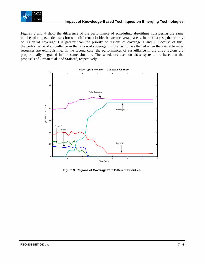
Figures 3 and 4 show the difference of the performance of scheduling algorithms considering the same number of targets under track but with different priorities between coverage areas. In the first case, the priority of region of coverage 3 is greater than the priority of regions of coverage 1 and 2. Because of this, the performance of surveillance in the region of coverage 3 is the last to be affected when the available radar resources are extinguishing. In the second case, the performances of surveillance in the three regions are proportionally degraded in the same situation. The schedulers used on these systems are based on the proposals of Orman et al. and Stafford, respectively.
0 2 4 6 8 10 12 140
0.2
0.4
0.6
0.8
1
1.2
1.4
Time (sec)
Occupancy
O&P Type Scheduler - Occupancy x Time
Total Occupancy
Tracking Load
Region 3
Region 2
Region 1
Figure 3: Regions of Coverage with Different Priorities.

Impact of Knowledge-Based Techniques on Emerging Technologies
7 - 6 RTO-EN-SET-063bis
0 2 4 6 8 10 12 140
0.2
0.4
0.6
0.8
1
1.2
1.4
Time (sec)
Occupancy
Mesar type scheduler - Occupancy x Time
Total occupancy
Tracking load
Region 3
Region 2
Region 1
Figure 4: Regions of Coverage with the Same Priorities.
An important aspect is that not only the scheduler but also the radar functions must be efficiently designed to avoid demanding unnecessary radar resources. For example, the tracking function should request updates only when they are important to keep the track of the targets. An adaptive tracking filter requests track updates based on the dynamics of the targets, on their degree of threatening etc. The more uncertainty there is about the targets, the more often requests will be generated in order to update the data about them. An analogous conclusion can be made when considering the surveillance function. The more uncertainty there is about the environment, the more often requests will be generated to collect data about it. Therefore, the previous knowledge of the tactical situation of the environment and the targets affects the performance of radar resource manager and the overall performance of the radar system.
Figures 5 and 6 show the influence of the previous knowledge of the identity of two targets in how often updates are performed by the radar. The targets are aircraft flying on the same trajectory. An adaptive Kalman filter was used to perform the tracking of the targets.

Impact of Knowledge-Based Techniques on Emerging Technologies
RTO-EN-SET-063bis 7 - 7
Figure 5: Tracking of a Friendly Target.
Figure 6: Tracking of an Enemy or an Unknown Target.
4.0 WAVEFORM DIVERSITY
4.1 Introduction Waveform diversity may be considered to be a development of multifunction phased array radar, in which a radar may simultaneously radiate and receive different signals in different directions for different purposes (which may include communications or ECM as well as strictly radar). The concept is shown pictorially in Figure 7. Such a scheme may entail adaptivity in the angular domain, in the time domain and in the coding domain (and conceivably in other domains as well), and the use of knowledge-based techniques in this processing has obvious attractions.

Impact of Knowledge-Based Techniques on Emerging Technologies
7 - 8 RTO-EN-SET-063bis
SensorCommunications
AMTI
GMTI
MaskingSignal
EmbeddedVoice/Data
CommunicationsNon-CooperativeBistatic Receiver
SensorCommunications
AMTI
GMTI
MaskingSignal
EmbeddedVoice/Data
CommunicationsNon-CooperativeBistatic Receiver
Figure 7: Concept of Waveform Diversity (after [16]).
In the succeeding paragraphs we discuss two important aspects of waveform diversity, namely target-matched illumination, in which it is shown that there is an optimum waveform for the detection of a given target, and spectral interpolation, which allows very high range resolution to be obtained from two (or more) spectrally-disjoint bands.
4.2 Target-Matched Illumination Principle: The concept of the matched filter was developed by Gjessing [21-23] and by Bell [2] to consider the optimum waveform for the detection of a target of a given range profile against a noise background. The target is characterized in terms of its impulse response as a function of delay time (i.e. range), which will also be a function of aspect angle (and therefore which in practice would require a library of target impulse responses versus aspect angle). The concept has been extended by Guerci and Pillai [19, 25, 30, 38] to include the detection of a target against nonhomogeneous noise, and also to the problem of discriminating different targets.
The problem is posed as follows (Figures 8, 9) using the notation adopted by Guerci. The radar transmits a signal s(t) towards a target, whose impulse response is hT(t). The echo signal y(t) is the convolution of s(t) with hT(t). To this is added noise n(t), so the received signal is
( ) ( ) ( )( ) ( )Tr t s t h t n t= ⊗ + (1)
where ⊗ denotes the convolution operator.

Impact of Knowledge-Based Techniques on Emerging Technologies
RTO-EN-SET-063bis 7 - 9
Figure 8: Whitening of the Target Impulse Response in Target-Matched Illumination.
Figure 9: The Target-Matched Illumination Problem (after Guerci [38]).
The receiver is characterized by its impulse response hR(t). The problem is then to choose s(t) and hR(t) to maximise the signal-to-interference ratio, which can be expressed in mathematical terms as follows:
( )0 0max maxs h
y tρ= (2)
where
( ) ( )( )
20
0 20 0
sy tSINR t
y tρ= = (3)
ys is the signal component of the output and yo is the component contributed by interference and noise.
The first step is to maximise the SNIR working on the receiver. Once the optimal impulse response of the receiver, HMF(t), has been determined, it follows (Figure 8) that :
( ) ( )( )20 2
1 Tf
ww Ti
SNIR y t dt f s tσ
= =∫ (4)
where Ti and Tf are the time boundaries of the receiver and yw(t) is the signal echo after the whitening filter.
At this stage, the problem is to maximise SNIR at the instant of detection t0 over the input signal s(t) of finite energy and duration. Grouping the expressions for both whitening filter and matched filter:
( ) ( )T wh t h h t⊗ (5)
whitened target impulse response
( ) ( ) ( ) ( )w t wy t s t h t h t= ⊗ +( )s t

Impact of Knowledge-Based Techniques on Emerging Technologies
7 - 10 RTO-EN-SET-063bis
Using this, the integral in (4) can be written
( ) ( ) ( ) ( )2 * *1 2 1 2 2 1
0 0
. . ,f
i
T T T
wT
y t dt s s K d dτ τ τ τ τ τ=∫ ∫ ∫ (6)
where
( ) ( ) ( )*1 2 1 2,
f
i
T
T
K h t h t dtτ τ τ τ− −∫ (7)
The solution must satisfy a homogeneous Fredholm integral of the second kind with Hermitian kernel:
( ) ( ) ( )max0
T
opt opts t s K t dλ τ τ τ= −∫ (8)
This principle can be extended to different models including signal dependent noise (clutter) [38] In this case, one must take the non-linear term into account in the signal to interference plus noise equation:
( ) ( ) ( )
( ) ( ) ( ) ( )( )
2
02 2
1 .2
1 . .2
fj TR T
R n c
H H S e dSINR
H G G S d
ωω ω ω ωπ
ω ω ω ω ωπ
+∞−
−∞+∞
−∞
=+
∫
∫ (9)
where
Gn(ω) is the additive noise spectrum Gc(ω) is the clutter spectrum HT(ω) and HR(ω) are the transmitter and receiver spectrum respectively
From the above model, we can derive three main cases:
1) The clutter is non significant compared to the additive noise Gc(ω) << Gn(ω)
2) The additive noise is non significant regards to the clutter Gc(ω) >> Gn(ω)
3) Clutter and noise are of equivalent power Gc(ω) ~ Gn(ω)
Unlike the first two cases, which can be solved by the previous method, the third one (clutter and noise) has been studied by Guerci using an iterative procedure [38].
Applications: Potential applications of matched illumination are:
• Identical target resolution (Figure 10);
• Target identification;
• Target tracking/tagging; and
• Target aspect uncertainty.

Impact of Knowledge-Based Techniques on Emerging Technologies
RTO-EN-SET-063bis 7 - 11
Figure 10: Target-Matched Illumination with Signal-Dependant Noise (clutter).
Further issues: The matched illumination has been obtained using information about the system under experiment. A straightforward problem is related to the ability of obtaining and processing the information in such way that it can be used for real applications. As a result, many papers dealing with classification algorithms are being published these days. In parallel with the development of knowledge based techniques is that of the pattern recognition. These methods are being developed to overcome the need for large libraries, and suggest that it is possible to characterize a target by isolating the influence of the strongest scatterers on the target signature.
Assuming a target can be described as a structure of scattering centres, the matched illumination can be applied to these sub-targets. Assuming these scattering centres are of relatively simple geometry, the required library would be much smaller. Furthermore, the extraction of intuitive scattering centres may lead to a fast method of recognition if part of an adaptive process. This method would combine both matched illumination (applied to major scattering centres in this case) and classification algorithm that would define the scattering centres to be extracted for a fast recognition.
4.3 Spectral Interpolation Another technique of interest is interpolation between two (or more) spectral bands to give the effect of a signal of very high bandwidth, and hence very high range resolution. The technique was originally proposed and demonstrated by workers at MIT Lincoln Labs [13], and demonstrated on S-band and C-band data from the COBRA JUDY shipborne radar system, to obtain high range resolution target profiles.
The scheme may be regarded as an extension of the superresolution techniques described in the third lecture of this series. It models the spectral signals in each sub-band with an all-pole model:
( )1
Pn
n k kk
M f a p=
= ∑ (10)
Following the notation of [13], the lower and upper sub-bands contain N1 and N2 samples respectively , so the sample index n ranges from n = 0, …, N1−1 for the lower sub-band and n = N−N2, …, N−1 for the upper sub-band. The poles pk characterize the relative ranges and frequency decay of the individual scattering centres. The sub-bands can be mutually cohered by fitting a separate all-pole model to each sub-band and adjusting the models until they are consistent.
Target impulse response hT(t)
Clutter channel
+
n(t)
r(t) y(t) s(t) Receiver impulse
response hr(t)

Impact of Knowledge-Based Techniques on Emerging Technologies
7 - 12 RTO-EN-SET-063bis
Next, forward-prediction matrices for the lower and upper sub-bands are constructed:
1 1
0 1
1
1
L
N L N
s s
s s
−
− −
⎛ ⎞⎜ ⎟
= ⎜ ⎟⎜ ⎟⎝ ⎠
H…
and 2 2 1
2
1
N N N N L
N L N
s s
s s
− − + −
− −
⎛ ⎞⎜ ⎟
= ⎜ ⎟⎜ ⎟⎝ ⎠
H
…
(11)
These are decomposed using singular value decomposition:
'1 1 1 1=H U S V and '
2 2 2 2=H U S V (12) where the prime denotes the Hermitian operator. The S matrices contain the singular values; the U and V matrices contain the corresponding eigenvectors. Thus the all-pole model parameters can be estimated as follows:
1) The singular value matrices S1 and S2 are used to estimate the model orders P1 and P2 for the two sub-bands;
2) P1 and P2 are used to partition V1 and V2 into orthogonal subspaces: a signal-plus-noise subspace and a noise subspace. A modified root-MUSIC algorithm is applied to estimate the signal poles for each sub-band;
3) The all-pole model amplitude coefficients ak are determined by using a linear least-squares fit to the measured data; and
4) The resulting sub-band signal models are adjusted to optimally match.
The paper presents results using 12 – 18 GHz radar data, reduced to two 1 GHz sub-bands (13 – 14 GHz and 16 – 17 GHz) and successfully reconstructs the missing spectral data.
5.0 BISTATIC, MULTISTATIC AND NETTED RADAR
5.1 Introduction Bistatic radar systems have been studied and built since the earliest days of radar. As an early example, the Germans used the British Chain Home radars as illuminators for their Klein Heidelberg bistatic system. Bistatic radars have some obvious advantages. The receiving systems are passive, and hence undetectable. The receiving systems are also potentially simple and cheap. Bistatic radar may also have a counter-stealth capability, since target shaping to reduce target monostatic RCS will in general not reduce the bistatic RCS. Furthermore, bistatic radar systems can utilize VHF and UHF broadcast and communications signals as ‘illuminators of opportunity’, at which frequencies target stealth treatment is likely to be less effective.
Bistatic systems have some disadvantages. The geometry is more complicated than that of monostatic systems. It is necessary to provide some form of synchronization between transmitter and receiver, in respect of transmitter azimuth angle, instant of pulse transmission, and (for coherent processing) transmit signal phase. Receivers which use transmitters which scan in azimuth will probably have to utilize ‘pulse chasing’ processing.

Impact of Knowledge-Based Techniques on Emerging Technologies
RTO-EN-SET-063bis 7 - 13
The combination of a number of transmitters and receivers in both monostatic and bistatic configurations, to form a netted radar system, offers the possibility of a further domain – the angular domain centered on the target – to exploit. Thus multistatic and netted radars are an area of considerable current interest.
The properties of bistatic radar have been described in detail by Willis [49, 50] and by Dunsmore [15]. Jackson [32] has analyzed the geometry of bistatic radar systems, and his notation (Figure 11) has been widely adopted.
Figure 11: Bistatic Radar Geometry.
From this:
( )
( )
2 21 2
21 22 sin R
r r Lr
r r L θ+ −
=+ +
(13)
Contours of constant bistatic range are ellipses, with transmitter and receiver as the two foci.
The bistatic radar equation is derived in the same way as the monostatic radar equation (Figure 12):
( )
2
3 2 21 2 04
t t r br
n
PG GPP r r kT BF
λ σπ
= (14)
Figure 12: Bistatic Radar Equation.
The factor ( )1 21 r r , and hence the signal-to-noise, has a minimum value for 1 2r r= . Thus the signal-to-noise ratio is highest for targets close to the transmitter or close to the receiver.
1r2r
transmitter receiver
θR
target
β
L
1r 2r
bσ
tGrG

Impact of Knowledge-Based Techniques on Emerging Technologies
7 - 14 RTO-EN-SET-063bis
Doppler shift depends on the motion of target, transmitter and receiver (Figure 13), and in the general case the equations are quite complicated [32, 50].
Figure 13: Bistatic Doppler (after Jackson [32]).
In the case when only the target is moving the Doppler shift is given by:
( )2 cos cos 2DVf δ βλ
⎛ ⎞= ⎜ ⎟⎝ ⎠
(15)
5.2 Application of Knowledge-Based Signal Processing to Bistatic, Multistatic and Netted Radar
Knowledge-based techniques may have several applications in bistatic and (particularly) multistatic radar systems. In a passive coherent location (PCL) system using broadcast or communications signals, the ambiguity behaviour of the waveform depends significantly on the type of signal and the modulation.
The waveform properties of a variety of PCL illuminators (VHF FM radio, analogue and digital TV, digital audio broadcast (DAB) and GSM at 900 and 1800 MHz) have been assessed at University College London by digitizing off-air waveforms and calculating and plotting their ambiguity functions [28, 29]. The receiving system was based on a HP8565A spectrum analyzer, digitizing the 21.4 MHz IF output by means of an Echotek ECDR-214-PCI digitizer card mounted in a PC. The system has the advantage of great flexibility, since the centre frequency and bandwidth of the receiver can be set by the controls of the spectrum analyzer. The rather high noise figure of the spectrum analyzer is not a disadvantage, since all of the signals are of high power and propagation is line-of-sight.
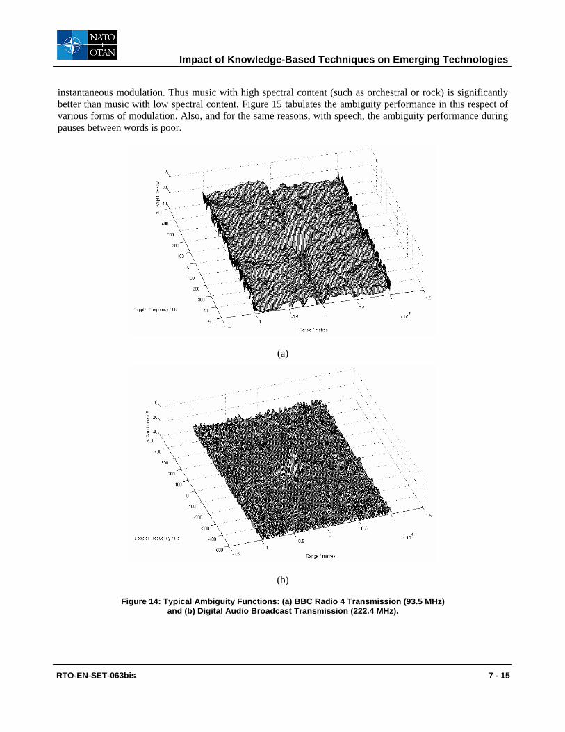
Figure 14 shows typical ambiguity functions derived using this system of (a) BBC Radio 4 at 93.5 MHz, for which the programme content is speech (an announcer reading the news), and (b) a digital audio broadcast (DAB) signal at 222.4 MHz. Both show range resolution appropriate to their instantaneous modulation bandwidths (9.1 and 78.6 kHz respectively), though the difference in the sidelobe structure is very evident, showing that the digital modulation format is far superior because the signal is more noise-like. Furthermore, it has been found that for analogue modulation formats the ambiguity performance depends strongly on the
transmitter receiver
target
β 2
L
RvTv
v
δT
θR
θT
β θ θ= − T R
Impact of Knowledge-Based Techniques on Emerging Technologies
RTO-EN-SET-063bis 7 - 15
instantaneous modulation. Thus music with high spectral content (such as orchestral or rock) is significantly better than music with low spectral content. Figure 15 tabulates the ambiguity performance in this respect of various forms of modulation. Also, and for the same reasons, with speech, the ambiguity performance during pauses between words is poor.
(a)
(b)
Figure 14: Typical Ambiguity Functions: (a) BBC Radio 4 Transmission (93.5 MHz) and (b) Digital Audio Broadcast Transmission (222.4 MHz).

Impact of Knowledge-Based Techniques on Emerging Technologies
7 - 16 RTO-EN-SET-063bis
signal frequency (MHz)
range resolution
(km)
effective bandwidth
(kHz)
peak range sidelobe level
(dB)
peak Doppler sidelobe level
(dB)
FM radio: speech (BBC Radio 4)
93.5 16.5 9.1 –19.1 –46.5
FM radio: classical music
100.6 5.8 25.9 –23.9 –32.5
FM radio: rock music (XFM)
104.9 6.55 22.9 –12.0 –26.0
FM radio: reggae (Choice FM)
107.1 1.8 83.5 –27.0 –39.5
DAB 219.4 1.54 97.1 –11.7 –38.0
Analogue TV: chrominance sub-carrier
491.55 9.61 15.6 –0.2 –9.1
Digital TV (DVB-T)
505.0 1.72 87.1 –18.5 –34.6
GSM 900 944.6 1.8 83.3 –9.3 –46.7
GSM 1800 1833.6 2.62 57.2 –6.9 –43.8
Figure 15: Properties of Ambiguity Functions of Various Types of Broadcast and Communications Signals.
This suggests that knowledge of the ambiguity performance of different sources may be used with advantage. Monitoring, in real time, of the instantaneous modulation of sources could be used to select the optimum sources.
Another aspect where knowledge-based techniques will be valuable is in multi-sensor tracking. Knowledge of the instantaneous resolution (in range and Doppler) in this way will indicate the appropriate way to combine the individual detections from each sensor. The knowledge-based tracking techniques discussed in the sixth of these lectures will be relevant here.
5.3 Bistatic Spatial Denial Another example of waveform diversity is the use of multiple transmitted waveforms from an airborne platform to deny the use of the radar as a bistatic illuminator [16]. Figure 16 shows the geometry, in which the radar transmits a signal towards the target. A hostile bistatic radar system attempts to ‘hitchhike’ off the radar, but requires a coherent reference signal for synchronization. Conventional methods to prevent the interception of the direct path signal include low sidelobe antennas, physical isolation, and the use of spread spectrum waveforms. In this technique the radar can radiate a suitably coded ‘masking signal’, which denies the coherent reference to the bistatic receiver (Figure 17).

Impact of Knowledge-Based Techniques on Emerging Technologies
RTO-EN-SET-063bis 7 - 17
Target
HostRadar
Spatially DeniedCoherent Reference
Non-CooperativeBistatic Sensor
Bistatic Receiver
Mainbeam
TransmitMainbeam
vvvvvv
vvvvvv
Target
HostRadar
Spatially DeniedCoherent Reference
Non-CooperativeBistatic Sensor
Bistatic Receiver
Mainbeam
TransmitMainbeam
vvvvvv
vvvvvv
Figure 16: Non-Cooperative Bistatic Receivers Require a Coherent Reference from the Host Illuminator.
Figure 17: Radar and Masking Signal Radiation Patterns.
The problem is therefore one of finding a radar waveform ur(t) with suitable ambiguity function, and a masking waveform um(t) which is orthogonal to the radar waveform over the full range and Doppler domain. The waveforms may be pulsed, quasi-CW or CW. Further, the radar waveform is radiated at a power Pt via a radiation pattern Fr(θ), and the masking waveform um(t) at a power Pm via a radiation pattern Fm(θ), and we require Fr(θ) and Fm(θ) to be spatially orthogonal, over the full bandwidth of the radar.
The overall performance of the scheme is quantified in terms of two parameters: (i) the degree of masking of the radar signal by the masking signal, and (ii) the degree of suppression of echoes (from targets or from clutter) of the masking signal in the channels of the radar receiver.
The performance of waveform codes is quantified in terms of their auto-ambiguity [52] and cross-ambiguity [39] functions:
ANENNA
Radar Signal
Masking Signal
ANTENNA
Radar signal Masking signal

Impact of Knowledge-Based Techniques on Emerging Technologies
7 - 18 RTO-EN-SET-063bis
2
2 *( , ) ( ) ( ) exp( 2 )D r Drf u t u t j f t dtχ τ τ π∞
−∞
= −∫ (16)
2
2
,
*( , ) ( ) ( ) exp( 2 )r m D r Dmf u t u t j f t dtχ τ τ π∞
−∞
= −∫ (17)
Several different waveform codes have been analyzed in this way, including co-channel chirp waveforms of opposite slope [20], pseudo-random binary sequences [27], and Costas codes [11, 24]. For this work the Costas signal is adopted for the host radar waveform because it yields a thumbtack-shaped ambiguity function with a relatively low pedestal. For a fixed number of frequency hops within a radar pulse there are many different hopping patterns that result in essentially the same thumbtack-shaped ambiguity function. Hence, different frequency hopping patterns can be utilized to further complicate the coherent reference estimation task of the non-cooperative radar.
The first approach to the design of radiation pattern is to use a linear array for the radar, with the masking signal radiated via N additional elements which form an interferometer. The two interferometric elements are driven separately with an independent waveform generation, timing and control circuit. Ideally, the interferometer antenna pattern will overlay the sidelobes of the host radar main antenna pattern with minimal overlay of the radar main beam. This will mask that portion of the host radar signal emitted through the radar sidelobes denying a coherent reference signal to a non-cooperative bistatic receiver.
Figure 18 shows the azimuthal radiation pattern of the interferometer array factor for N = 4 and 5. We notice major lobes at α =0° and 180° as well as major lobes or nulls at α =±90° for N odd or even respectively. In the case where nulls appear at α =±90° we notice something of particular interest. The derivative of the array factor at α =±90° is zero, which means that the nulls at those angles have zero slope. This makes those particular nulls broader than the rest of the nulls. To avoid self-jamming of the radar waveform, it may be desirable to steer the interferometer pattern such that the main beam of the host radar is centered in this broad null. To achieve this interferometer steering and obtain a broad null at α =0 we place the interferometer on the y-axis keeping the linear array of the main radar along the x-axis. Assuming that the interferometer elements spacing is measured in units of half wavelength dIFM = ks (λ/2) we notice that a broad null exists at α = 0° only for odd ks. This is shown in Figure 19 for ks=7. In this case broad nulls occur broad side to the main radar antenna in both the horizontal and vertical planes guaranteeing the orthogonality property between radar and masking signal. Since the interferometer excitation is likely to be considerably smaller than the radar excitation, placement of the broad null of the interferometer at the center of the main beam of the radar is likely to be an effective technique from preventing the interferometer signal from interfering with the desired radar target returns.

Impact of Knowledge-Based Techniques on Emerging Technologies
RTO-EN-SET-063bis 7 - 19
Figure 18: Azimuthal Radiation Pattern for a) N=4 and b) N=5.
90
-90
60120
150 30
- 150 -30
-60-120
180 0 Y
X
90
-90
60120
150 30
- 150 -30
-60-120
180 0
90
-90
60120
150 30
- 150 -30
-60-120
180 0 YY
X
Figure 19: Azimuthal Radiation Pattern for Steered Interferometer and ks=7.
Notice that as the number of interferometer elements N increases, both the broad null as well as the spacing between sidelobes widens, thereby decreasing masking coverage in the direction of a potential non-cooperative radar. One possible method to overcome this deficiency is to change the configuration of the interferometer so as to form a triangle with three elements. This pattern is more irregular, but does have increased coverage despite being at a lower amplitude.
The second approach uses an N-element linear antenna array. Suppose initially that the array is fed by a Butler Matrix [9] (Figure 20). This generates a set of spatially-orthogonal antenna beams, each of the form
1 sin( / 2)| |
sin( / 2)NE
Nψ
ψ= (18)
with
( )sinkdψ θ δλ
= − (19)
90
-90
60 120
150 30
-150 - 30 -60 -120
180 0 Y
X90
-90
60 120
150 30
-150 - 30 -60 -120
180 0 Y
X90
-90
60 120
150 30
-150 - 30 -60 -120
180 0
90
-90
60 120
150 30
-150 - 30 -60 -120
180 0 Y Y
XX
Y
X 90 60120
150 30
- 150 -30
- 60- 120
180 0
90 60120 150 30
- 150 -30
- 60- 120
180 0 YY
X X

Impact of Knowledge-Based Techniques on Emerging Technologies
7 - 20 RTO-EN-SET-063bis
where d is the element spacing, λ is the wavelength, k = 2π/λ, θ is the azimuth angle and δ is the angle of the maximum of the particular beam. For an N-element array
( )2 1
m
m
N
πδ
−= (20)
so the normalized far-field pattern of the mth beam is
( ) ( )[ ]( ){ }
( ) ( )[ ]( ){ }sin 2 sin 2 1 21
sin 2 sin 2 1 2m
N kd m NE
N kd m N
θ π
θ π
− −=
− − (21)
Butler matrix
Antenna’s linear array of elements
beam ports
Figure 20: Linear Array and Butler Matrix.
The orthogonality of this set of beams is maintained over a broad bandwidth, dictated by the hardware of the Butler Matrix, but typically an octave or more. In order for this to be so, the beamwidths and directions of the beams must change with frequency. The beams have a first sidelobe level of –13.2 dB, which is rather high for radar purposes; the sidelobe level can be lowered by an amplitude taper across the array in the usual way, but this destroys the orthogonality condition. The set of beams may be steered electronically by a set of phase shifters, either at the antenna elements or at the beam ports.
Suppose that one of the central beams is used for the radar, both for transmitting and receiving. One or more of the remaining beams is used to radiate the masking signal or signals, at an appropriate relative power level. Furthermore, if the radar signal and masking signal(s) were to be generated at the beam ports of the Butler Matrix by direct digital synthesis, which could include the effect of phase shifts to steer the beams electronically, then since the signals radiated from each element are simply weighted combinations of the beam port signals, the element signals may be calculated and generated directly, without any need for the Butler Matrix hardware.
To evaluate the performance of a given system it is necessary to specify a value for the degree of masking. In practice this will vary with direction θ, so may be specified as a peak value or as a mean averaged over the sidelobe region of Fr(θ). Thus we define
( )( )( )
r r
m m
P FLP F
θθθ
= (22)

Impact of Knowledge-Based Techniques on Emerging Technologies
RTO-EN-SET-063bis 7 - 21
with Pm and Pr the power levels at which the masking and radar signals are transmitted. This is the radar signal to masking signal ratio for the case of an adversary listening from a particular angle θ. This ratio depends on the geometry of the antennas used and their radiation pattern. The required degree of masking represents a compromise on one hand by the need to disrupt the coherent reference, and on the other hand not to disrupt the operation of the radar. From a knowledge of the effect of ECM, a value of about 13 dB is likely to be adequate. The value of L at θ = 0 (i.e. at the centre of the host radar main lobe) will obviously take negligible values, first because of the broad null of the masking signal at this angle and secondly because of the coding of the signals. An adversary could only recover the radar signal if listening from that specific direction.
The suppression of the masking signal in the radar receiver will include the echoes received from the target and clutter. The masking signal levels will be further suppressed because the filter at the receiver is matched to the radar signal. The echo of the masking signal is relative to mm FP . Similarly the echo of the radar signal is relative to rr FP . These are received by the radar antenna pattern which for the present we will consider to be the same as the transmit radar pattern. The following two expressions can thus be written down:
( ) ( )m m m TAR r RECS P F Fθ θ= (23)
( ) ( )r r r TAR r RECS P F Fθ θ= (24)
These are applied to the matched filter for the radar signal. The degree of suppression of the masking signal is therefore:
2
2
( ) ( ) ( ) ( )( )
( ) ( ) ( ) ( )
D
D
j f tm m TAR r REC m r
j f tr r TAR r REC r r
P F F u t u t e dtR
P F F u t u t e dt
π
π
θ θ τθ
θ θ τ
∞∗
−∞∞
∗
−∞
−=
−
∫
∫ (25)
where: mP is the power level of the transmitted masking signal;
rP is the power level of the transmitted radar signal; ( )m TARF θ is the Doppler shifted echo of the masking signal from the target; ( )r TARF θ is the Doppler shifted echo of the radar signal from the target; ( )r RECF θ is the radar signal at reception;
∫∞
∞−
∗− dtetutu tfjrm
Dπτ 2)()( is the response to the masking signal of the filter matched to the radar signal (cross
ambiguity function); and
∫∞
∞−
∗− dtetutu tfjrr
Dπτ 2)()( is the response to the radar signal of the filter matched to the radar signal (auto
ambiguity function).
Figure 22 shows a typical result, corresponding to Pr/Pm = 10 dB, for the interferometer scheme and for the Costas-coded signal whose ambiguity function is depicted in Figure 21. The plot shows the degree of

Impact of Knowledge-Based Techniques on Emerging Technologies
7 - 22 RTO-EN-SET-063bis
suppression of the masking signal in the radar receiver, according to equation (25), as a function of range and of angle. It can be seen that, within the main lobe of the radar antenna pattern the masking signal is suppressed to a very low level, both because the masking signal radiation pattern has a null in that direction, and also because the orthogonality of the masking signal code to the radar signal is very high at zero Doppler (boresight). Outside the main lobe region the degree of suppression is about 30 dB. A different value of Pr/Pm would simply shift this characteristic up or down.
Figure 21: Auto-ambiguity Function of a Costas Signal for N=30 (linear scale).
Figure 22: Degree of Suppression of Masking Signal in the Radar Receiver (for interferometer scheme and for Costas coded signal of Figure 21 with Pr/Pm = 10 dB).
range angle
dB

Impact of Knowledge-Based Techniques on Emerging Technologies
RTO-EN-SET-063bis 7 - 23
6.0 SYNTHETIC APERTURE RADAR
High-resolution synthetic aperture radar is now widely used for military surveillance as well as in geophysical remote sensing applications. Whilst huge volumes of image data are readily generated, one of the major challenges is to extract information from those images in a reliable and efficient manner, and Oliver and Quegan’s book [35] is devoted to this problem. The use of prior information in a knowledge-based approach is clearly attractive.
Conventionally, the target detection problem is tackled by comparing the value of the image pixel under test against the statistical distribution of the surrounding pixels. If the observed value of the pixel is unlikely to occur as a result of the clutter, then a target is declared to be present. This forms the basis of classical CFAR algorithms. Blacknell [7] has considered the use of what he calls ‘context’ in this problem. Thus the likelihood of a target being present will be influenced by the image context – for example, military vehicles will tend to be parked in groups close to hedges and the edges of woods rather than individually in the middle of open ground. This contextual information can be exploited by allowing the target probability P(t) to vary as a function of spatial position, depending on the context. This will mean that the detection threshold used in the likelihood ratio test will vary with spatial position, and hence the false alarm rate will not be constant over the scene.
Following Blacknell’s description and notation [7], consider a particular image position at which the target probability is ( ) ( )Q t P tα= , where P(t) is the target probability associated with a nominal probability of false alarm, PFA. Then the value xα above which a target is declared is:
( ) ( ) ( ) ( )0b bP x cQ t cP t P xα α α≅ = = (26) and the probability of false alarm is given by:
( ) ( )FA bx
P P x dxα
α∞
= ∫ (27)
For SAR images, the standard background model is given by the negative exponential distribution, which describes the speckle fluctuations that arise in coherent imaging systems:
( ) 1 expbb b
xP xµ µ
=⎛ ⎞
−⎜ ⎟⎝ ⎠
(28)
which gives a probability of false alarm of
0expFAb
xPµ
=⎛ ⎞
−⎜ ⎟⎝ ⎠
(29)
and hence a pixel intensity threshold of ( )0 lnb FAx Pµ= − (30)

Impact of Knowledge-Based Techniques on Emerging Technologies
7 - 24 RTO-EN-SET-063bis
Thus, given a modified target probability, manipulation of the above equations gives the modified pixel intensity threshold: ( )0 lnbx xα µ α= − (31) and the modified probability of false alarm
( ) ( )exp lnFA FAb
xP Pα α αµ
=⎛ ⎞
− + =⎜ ⎟⎝ ⎠
(32)
The technique was demonstrated using simulated data. Three types of contextual information were considered: the terrain type, the proximity of hedges, and the proximity of other targets. Military targets are more likely to travel through fields than through woods, so terrain type is relevant. Also, military vehicles will tend to travel in groups and will be parked near hedges rather than in the open, to make detection more difficult.
The results showed consistent improvements in detection rates, with a 13±1% increase in the number of targets detected when all of the contextual influences considered were present. Blacknell states: ‘The challenge for the future is to quantify in statistical terms the contextual influences in a real SAR scene and to trial the detection scheme against realistic military deployments of targets’.
7.0 CONCLUSIONS
The examples presented in this tutorial have attempted to show the great potential of knowledge-based processing techniques in future-generation radar systems. The examples presented – in multifunction phased array radar, target-matched illumination and spectral interpolation (as examples of waveform diversity), bistatic radar, and synthetic aperture radar, have all attempted to show how prior information on the target scene and the targets themselves can be exploited.
A further comment is that advances in processing and algorithms are far easier to incorporate in practical radar systems than advances in hardware. A radar system with a planned lifetime of (say) twenty years can be designed so that new algorithms can be incorporated straightforwardly, rather than with radical, expensive modifications.
8.0 ACKNOWLEDGEMENTS
I gratefully acknowledge invaluable discussions with many people from whom I have learned much about radar and signal processing over the years. I would particularly like to mention Chris Baker, David Blacknell, DEN Davies, Alfonso Farina, Richard Klemm, Simon Watts, Richard White, Mike Wicks and Nick Willis. I am also grateful to the students with whom I have worked on these subjects over the years, in particular Hervé Borrion, Joe Butler, Shirley Coetzee, Glen Davidson, Ioannis Fotinopoulos, Sergio Miranda, Dominic Walker and Aric Whitewood, and to the organisations, including the UK Ministry of Defence, the US Air Force Office of Scientific Research, the UK Engineering and Physical Sciences Research Council, QinetiQ and its predecessors, BAE SYSTEMS, Thales Sensors and AMS, who have supported the various projects.

Impact of Knowledge-Based Techniques on Emerging Technologies
RTO-EN-SET-063bis 7 - 25
9.0 REFERENCES
[1] Adve, R., Antonik, P., Baldygo, W., Capraro, C., Capraro, G., Hale, T., Schneible, R. and Wicks, M., ‘Knowledge-base application to ground moving target detection’, AFRL-SN-RS-TR-2001-185, September 2001.
[2] Bell, M., ‘Information theory and radar waveform design’, IEEE Trans. Information Theory, Vol.39, No.5, pp. 1578-1597, 1993.
[3] Berry, P.E. and Fogg, D.A.B., ‘On the use of entropy for optimal radar resource management and control’, (to be presented at First Australian International Radar, Conference, Adelaide, 3 – 5 September 2003.
[4] Billingsley, J.B., Low Angle Radar Land Clutter: Measurements and Empirical Models, SciTech / Peter Peregrinus, 2002.
[5] Blacknell, D., ‘Target detection in correlated SAR clutter’, IEE Proc. Radar, Sonar and Navigation, Vol.147, No.1, pp. 9-16, February 2000.
[6] Blacknell, D., ‘Statistical target behaviour in SAR images’, IEE Proc. Radar, Sonar and Navigation, Vol.147, No.3, pp. 143-148, June 2000.
[7] Blacknell, D., ‘Contextual information in SAR target detection’, IEE Proc. Radar, Sonar and Navigation, Vol.148, No.1, pp. 41-47, February 2001.
[8] Brennan, L.E. and Reed, I.S., ‘Theory of adaptive radar’, IEEE Trans. Aerospace & Electronic Systems, Vol.AES-9, No.2, pp. 237-252, March 1973.
[9] Butler, J.L., ‘Digital matrix and intermediate frequency scanning’, Chapter 3 in Microwave Scanning Antennas, Volume III, (R.C. Hansen ed.), Peninsula Publishing, 1985.
[10] Butler, J.M., Moore, A. and Griffiths, H.D., ‘Multifunction radar resource management for the tracking function’, Proc. RADAR’97 Conference, Edinburgh; IEE Conf. Publ. No. 449, pp. 568–572, 14–16 October 1997.
[11] Costas, J.P., ‘A study of a class of detection waveforms having nearly ideal range-Doppler ambiguity properties’, IEEE Trans. Information Theory, Vol.IT-28, No.4, pp. 600-604, July 1982.
[12] Cripps, S.C., RF Power Amplifiers for Wireless Communications, Artech House, 1999.
[13] Cuomo, K.M., Piou, J.E. and Mayhan, J.T., ‘Ultra-wideband coherent processing’, Special issue of The Lincoln Laboratory Journal on Superresolution, Vol. 10, No.2, pp. 203-221, 1997.
[14] Drabowitch, S., Papiernik, A., Griffiths, H.D., Encinas, J. and Smith, B.L., Modern Antennas, Chapman & Hall / IEEE MTT, ISBN 0 412 57910 3, 1997.
[15] Dunsmore, M.R.B., ‘Bistatic radars’, chapter 11 in Advanced Radar Techniques and Systems (G. Galati ed.), Peter Peregrinus, 1993.

Impact of Knowledge-Based Techniques on Emerging Technologies
7 - 26 RTO-EN-SET-063bis
[16] Ertan, S., Wicks, M.C., Antonik, P., Adve, R., Weiner, D., Griffiths, H.D. and Fotinopoulos, I., ‘Bistatic denial by spatial waveform diversity’, Proc. RADAR 2002 Conference, Edinburgh; IEE Conf. Publ. No.490, pp. 17-21, 15 – 17 October 2002.
[17] Farina, A. and D’Addio, E., ‘Overview of detection theory in multistatic radar’, IEE Proc., Vol.133, Pt.F., No.7, pp. 613-623, December 1986.
[18] Farina, A., Antenna-based Signal Processing Techniques for Radar Systems, Artech House, 1991.
[19] Garren, D.A., Osborn, M.K., Odom, A.C., Goldstein, J.S., Pillai, S.U. and Guerci, J.R., ‘Enhanced target detection and identification via optimized radar transmission pulse shape’, IEE Proc. Radar, Sonar and Navigation, Vol.148, No.3, pp. 130-138, June 2001.
[20] Giuli, D., Fossi, M. and Facheris, L., ‘Radar target scattering matrix measurement through orthogonal signals’, IEE Proc, Pt.F., Vol.140, No.4, pp. 233-242, August 1993.
[21] Gjessing, D.T., ‘Adaptive techniques for radar detection and identification of objects in an ocean environment’, IEEE J. Ocean Engineering, Vol.6, No.1, pp5-17, 1981.
[22] Gjessing, D.T., Target Adaptive Matched Illumination Radar: Principles and Applications, Peter Peregrinus, 1986.
[23] Gjessing, D.T. and Saebboe, J., ‘Bistatic matched illumination radar involving synthetic aperture and synthetic pulse for signal to clutter enhancement and target characterization’, Proc. 2001 CIE International Conference on Radar, Beijing, pp. 20-24, 15 – 18 October 2001.
[24] Golomb, S.W. and Taylor, H., ‘Construction and properties of Costas arrays’ Proc. IEEE, Vol.72, No.9, pp1143-1163, September 1984.
[25] Grieve, P.G. and Guerci, J.R., ‘Optimum matched illumination-reception radar’, US Patent S517522, 1992.
[26] Griffiths, H.D. and Carter, S.M., ‘Provision of moving target indication in an independent bistatic radar receiver’, The Radio and Electronic Engineer, Vol.54, No.7/8, pp. 336-342, July/August 1984.
[27] Griffiths, H.D. and Normant, E., ‘Adaptive SAR beamforming network’, European Space Agency Contract Report, Contract No. 6553/89/NL/IW, ESA Technical and Publications Branch, ESTEC, Noordwijk, 1990.
[28] Griffiths, H.D., Baker, C.J., Ghaleb, H., Ramakrishnan, R. and Willman, E., ‘Measurement and analysis of ambiguity functions of off-air signals for passive coherent location’, Electronics Letters, Vol.39, No.13, pp. 1005-1007, 26 June 2003.
[29] Griffiths, H.D., ‘From a different perspective: principles, practice and potential of bistatic radar’, (to be presented at First Australian International Radar, Conference, Adelaide, 3 – 5 September 2003.
[30] Guerci, J.R., ‘Optimum matched illumination-reception radar for target classification’, US Patent S5381154, 1995.

Impact of Knowledge-Based Techniques on Emerging Technologies
RTO-EN-SET-063bis 7 - 27
[31] Izquierdo-Fuente, A. and Casar-Corredera, J.R.; ‘Optimal radar pulse scheduling using a neural network’, Proc. IEEE International Conference on Neural Networks, 1994.
[32] Jackson, M.C., ‘The geometry of bistatic radar systems’ IEE Proc., Vol.133, Part F., No.7, pp. 604-612, December 1986.
[33] Morgan, C. and Moyer, L., ‘Knowledge base applications to adaptive space-time processing, volume IV: knowledge-based tracking’, AFRL-SN-RS-TR-2001-146 Vol.IV, July 2001.
[34] Morgan, C. and Moyer, L., ‘Knowledge base applications to adaptive space-time processing, volume V: knowledge-based tracker rule book’, AFRL-SN-RS-TR-2001-146 Vol.V, July 2001.
[35] Oliver, C.J. and Quegan, S., Understanding Synthetic Aperture Radar Images, Artech House, 1998.
[36] Orman et al., ‘Scheduling for a multifunction phased array system’, European Journal of Operational Research, No. 90, 1996.
[37] Pell, C. and Hanle, E. (eds), Special Issue of IEE Proceedings Part F. on Bistatic Radar; IEE Proc., Vol.133, Pt.F., No.7, December 1986.
[38] Pillai, S.U., Oh, H.S., Youla, D.C. and Guerci, J.R., ‘Optimum transmit-receiver design in the presence of signal-dependent interference and channel noise’, IEEE Trans. Information Theory, Vol.46, No.2, pp. 577-584, March 2000.
[39] Rihaczek, A.W., Principles of High Resolution Radar, McGraw-Hill, New York, 1969; reprinted by Artech House, Norwood, MA, 1996.
[40] Salama, Y. and Senn, R., ‘Knowledge base applications to adaptive space-time processing, volume I: summary’, AFRL-SN-RS-TR-2001-146 Vol.1, July 2001.
[41] Salama, Y. and Senn, R., ‘Knowledge base applications to adaptive space-time processing, volume VI: knowledge-based space-time adaptive processing (KBSTAP) user’s manual and programmer’s manual’, AFRL-SN-RS-TR-2001-146 Vol.VI, July 2001.
[42] Schuman, H., ‘Knowledge base applications to adaptive space-time adaptive processing, volume II: airborne radar filtering’, AFRL-SN-RS-TR-2001-146 Vol.II, July 2001.
[43] Schuman, H., ‘Knowledge base applications to adaptive space-time adaptive processing, volume III: radar filtering rule book’, AFRL-SN-RS-TR-2001-146 Vol.III, July 2001.
[44] Stafford, W.K.; ‘Real time control of a Multifunction Electronically Scanned Adaptive Radar (MESAR)’, IEE Colloquium on Real Time Management of Adaptive Radar Systems, June 1990.
[45] Strömberg D. and Grahn P.; ‘Scheduling of tasks in phased array radar’, Proc. IEEE International Symposium on Phased Array Systems and Technology, 1996.
[46] Tsao, T., Slamani, M., Varshney, P., Weiner, D., Schwarzlander, H. and Borek, S., ‘Ambiguity function for a bistatic radar’, IEEE Trans. Aerospace and Electronic Systems, Vol.33, No.3, pp1041-1051, July 1997.

Impact of Knowledge-Based Techniques on Emerging Technologies
7 - 28 RTO-EN-SET-063bis
[47] Van Trees, H.L., Detection, Estimation and Modulation Theory, Part I, Wiley, New York, 1968.
[48] Vine, M. T.; ‘Fuzzy logic in radar resource management’, Multifunction Radar and Sonar Sensor Management Techniques (Ref. No. 2001/173), IEE, 2001.
[49] Willis, N.J., ‘Bistatic radar’, chapter 25 in Radar Handbook (second edition), (M.I. Skolnik ed.), McGraw-Hill, 1990.
[50] Willis, N.J., Bistatic Radar, Artech House, 1991.
[51] Wirth, W-D., Radar Techniques using Array Antennas, Peter Peregrinus, 2001.
[52] Woodward, P.M., Probability and Information Theory, with Applications to Radar, Pergamon Press, 1953; reprinted by Artech House, 1980.