impact of new flexible load operation and grid codes on...
TRANSCRIPT

Authors: Dr.-Ing. Ana Joswig Dr.-Ing. Hendrik Steins Dipl.-Ing. Jürgen R. Weidner Siemens AG Power Generation Services Power and Gas
Impact of New Flexible Load Operation and Grid Codes on Turbine Generators with a Focus on End Windings
Power Gen Europe 2015 June 9-11, 2015 Amsterdam, the Netherlands
siemens.com
AL: N; ECCN: N Unrestricted © Siemens AG 2015. All rights reserved. Page 2 of 25
Table of Contents
1 Abstract ...............................................................................................................3
2 Introduction .........................................................................................................4
3 Evaluation of Operating Regimes ........................................................................6
4 New Grid Demands and Effects on Generator Components .................................9
5 FEM Calculation of Stator Winding .................................................................. 13
6 Possible Solutions and Mitigations .................................................................... 15
6.1 Online Monitoring and Offline Diagnostics ................................................... 15
6.2 Dynamic & Active Regulation of Cooling Gas Temperature.......................... 16
6.3 Advanced Stator End Winding Design for Direct Hydrogen-Cooled Stators .. 18
6.4 Lifetime Extension Management of Old Generators ...................................... 20
7 Conclusion ........................................................................................................ 22
8 References ......................................................................................................... 23
9 Disclaimer ......................................................................................................... 24

AL: N; ECCN: N Unrestricted © Siemens AG 2015. All rights reserved. Page 3 of 25
1 Abstract The integration of renewable energy sources with preferred feed in the high voltage
transmission system results in fundamental changes in the global and local load regime of the
European transmission grid. New power plant operation demands need to be defined for
conventional units. The turbine generator as the key electrical component of the plant will
face new operational stresses created by the more flexible grid behavior. To handle this novel
situation, the Agency for the Cooperation of Energy Regulators (ACER) of the European
Commission in Brussels has elaborated a new European grid code called the European
Network Code for Transmission System Operators including Requirements for Generators
ENTSO-E NC RfG. This is a framework of requirements covering the spectrum of the
different national grid codes.
The new European Network Code requires higher flexibility in the operating conditions of the
power plant generator to maintain a secure power supply and grid stability.
The consequences of this new network code for currently operating generators in power
plants and especially for the design and manufacture of future generators are set forth in this
paper. The correlation between individual grid code requirements, extrapolated mechanical
utilization stresses and affected generator components is demonstrated with examples. In a
comparison of different designs of turbine generators, the effects of individual grid code
requirements on specific components such as the stator core, windings, bearings and shafting
train are presented based on qualitative analysis. The impact of fast load changes on the stator
bars is further investigated based on FEM analysis of the stator end windings.
Possible mitigations and solutions are presented for generators which have been in service for
many years and are now confronted with the new grid demands.

AL: N; ECCN: N Unrestricted © Siemens AG 2015. All rights reserved. Page 4 of 25
2 Introduction The integration of renewable energy sources with preferential feed into the high-voltage
transmission system results in fundamental changes in the load regime of the European grid.
Conventional power plants will be significantly displaced from the market or used as reserve
capacity for when the renewable energy plants are unable to generate the total output required
in the grid. In addition to grid operation requirements, the operating regime of the
conventional power plants required to cover the supply gap is based especially on aspects of
cost-effectiveness under consideration of the borderline implementation costs of the respective
power plant.
Fig. 1 shows the example contributions of wind and solar energy to the total generating
capacity in the spring and winter over a period of one week in March and December 2014 [1].
During sunny weather in March, photovoltaics (solar – yellow) provide roughly ¼ of the
required energy at midday, while hard coal power plants (HC – black) provide the regulating
power reserve. With the change in weather over the weekend (Sat – Sun), wind power (gray)
provides up to nearly 50% of the power demand, and even nuclear power plants (Uranium –
red) have to throttle their output. Most of the hard coal power plants are disconnected from the
grid at this point. The situation for electric power generation is completely different in the
selected week in December. No wind or solar energy are available from Tue - Sat due to the
weather situation. The conventional coal and gas-fired power plants now have to weigh in and
close the supply gap.
Fig. 1: Weather-dependent fluctuations in the contribution to electric power generation from wind and solar
plants (Fraunhofer Institute for Solar Energy Systems (ISE) Freiburg, 2015-01-07)
March 2014 December 2014

AL: N; ECCN: N Unrestricted © Siemens AG 2015. All rights reserved. Page 5 of 25
The contribution to electric power production from renewable energy sources (especially
wind power and photovoltaics) is increasing continuously in Germany. This gives rise to a
large dependency on the weather, and results in permanent fluctuations in the utilization of
conventional power plants, with the consequence of an extremely volatile operating mode at
times. The number of startup and shutdown cycles for peak load power plants increases
significantly. Power plants remain in turning gear operation more frequently and for longer
periods, and standstill hours also increase. Load changes in operation are more frequent, and
output gradients also increase (e.g. due to unpredictable changes in weather and priority of
renewable energy sources). Overall utilization of the power plants is only partial or very low,
resulting in uneconomical operation. The evaluation of power plant operating data has
revealed this special operating mode not only in Germany but also throughout Europe. (Ref.
[3])
This is highlighted by an evaluation of the operating mode of 32 power plant units in
southwestern Europe. The diagram in Fig. 2 shows the change from base load and lower
medium load to peak load operation with 10 – 70 h/start in many gas-fired power plants
within only 4 years. Most new power plants ( ) are operated in peak load or upper medium
load from the start.
Fig. 2: Changes in operating mode of 32 power plant units over the period from 2008 to 2012 in southwestern
Europe due to the deployment of renewable power generation
AL: N; ECCN: N Unrestricted © Siemens AG 2015. All rights reserved. Page 6 of 25
In addition to use of power plants which can be scheduled over the medium term, such as for
seasonal and weekend load levels, short-term operation or load fluctuations due to volatile
wind and solar power in particular require that the conventional power plants now fulfill the
role of a regulating power reserve. The amplitude of load fluctuations between times of
maximum and minimum power generation from renewable sources increases with increasing
renewable power generation (this is especially characterized by the power input from
photovoltaic systems) as well as the weather-related load fluctuations, especially between
phases of strong and light winds.
Increased wear is anticipated in conventional power plants used to compensate these
fluctuations. It is absolutely necessary to adjust the design and maintenance of the "generator"
component in the power plant to this changed operating mode.
3 Evaluation of Operating Regimes
The new situation in power generation as a result of the transition to renewable energy means
that the operating modes of conventional power plants or their generators can differ greatly,
even if these generators are of the same type or output range.
The operating modes of 33 plants worldwide with generators of the same type (indirectly
cooled generators in the 300 MVA class) were analyzed in a detailed investigation. These
plants cover the entire range from base-load to peak-load power plants.
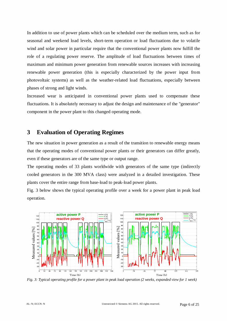
Fig. 3 below shows the typical operating profile over a week for a power plant in peak load
operation.
Fig. 3: Typical operating profile for a power plant in peak load operation (2 weeks, expanded view for 1 week)
Mea
sure
d va
lues
[%]
Mea
sure
d va
lues
[%]
Time [h] Time [h]
active power P reactive power Q
active power P reactive power Q

AL: N; ECCN: N Unrestricted © Siemens AG 2015. All rights reserved. Page 7 of 25
In addition to a daily start/stop cycle, it is clearly evident that the generator is not in a steady-
state thermal condition in grid operation, as the power plant frequently has to be operated at
full load, part load and low load.
A further example of volatile operation, focusing on active and reactive power, is shown
below (Fig. 4).
Fig. 4: Active and reactive power for a typical grid demand profile
The frequently occurring and steep active power gradients form a further important
characteristic. These gradients are necessary to compensate for the weather-related
fluctuations in renewable energy (Fig. 4, 16 – 20h). Reactive power input is similarly volatile.
This provides the necessary voltage stabilization in the grid, as renewable energy sources can
generally only provide limited grid support. It is clear that generators will be operated
increasingly frequently in an underexcited state (negative reactive power).
Fig. 5 shows a compact representation of the load points and load gradients for a generator
during overall operation. The left-hand image shows the relative frequency of the operating
points in the capability curve at which the generator operates. The broad scatter clearly
reflects the operating modes described above. Grid demand forces the generator represented
active power P reactive power Q
Mea
sure
d va
lues
[%]
Time [h]

AL: N; ECCN: N Unrestricted © Siemens AG 2015. All rights reserved. Page 8 of 25
here to remain in underexcited low-load, part-load and full-load operation for nearly 50% of
the operating period.
In addition to the load points at which the generator operates it is extremely important to
examine in detail how quickly the generator switches between the different load points.
Fig. 5: Distribution of load points and load gradients for a generator with highly volatile utilization.
The image on the right in Fig. 5 shows the relative frequency of the generator load gradient,
distinguished between active and reactive load gradients, over the entire operating period. The
broad scatter out to higher amplitudes reflects the high demand from the grid for generator
flexibility.
The operating modes recorded in detail here result in increased fatigue in the plant and
accelerated wear of individual components.

AL: N; ECCN: N Unrestricted © Siemens AG 2015. All rights reserved. Page 9 of 25
4 New Grid Demands and Effects on Generator Components The additional demands on power plants resulting from the volatile grid demand are largely
known and are accounted for in the current specifications of the European Network Code. The
relevant specifications for behavior of the power generation units connected to the grid are
especially defined in the Network Code "Requirements for Grid Connection applicable to all
Generators" (NC RfG) [4] and are further explained in a corresponding application guideline
[5]. The determining requirements for the power plant/grid interface are significantly more
stringent in comparison with the previously applicable regulations in NC RfG, and in part
exceed the degree regarded as reasonable and necessary from the standpoint of the utilities.
Eurlectric and the VGB show in [7] that significant additional costs will result for generator
operation.
Some of these future requirements for generators are described in further detail and are put in
technical context as examples below. Possible damage scenarios, especially for older
generators, are listed under consideration of physical relationships.
In particular, these are an elevated frequency range (47.5 Hz - 51.5 Hz) and an elevated
voltage range (85% - 115%). This increases the risk of extremely high stator magnetization
(high flux densities for high voltages at low speed), resulting in the formation of hot spots.
The rotor must provide this induction, which results in elevated rotor currents and to possible
rotor overheating. Examples of such cases are shown in Fig.6.
Fig.6: Potential effects of high rotor currents and high stator induction
Local overheating in dovetail bar area of stator core back caused by excessive magnetic flux
Thermal deformation of copper conductors and overheating of turn insulation on rotor endwinding caused by high rotor current

AL: N; ECCN: N Unrestricted © Siemens AG 2015. All rights reserved. Page 10 of 25
The increased number of start/stop cycles mentioned above results in increased thermal
fatigue due to the fluctuating thermal cycles. This can result in damage to the conductors and
the insulation (Fig. 7).
Fig. 7: Potential damage to conductor and insulation due to thermal fluctuations
Finally, the high and frequent output gradients (at up to 24% of rated output) cause faster
expansion and contraction of the windings and correspondingly greater thermo-mechanical
stress on the material surfaces.
This results in accelerated aging in older generators which have previously been operated in
base load and at lower medium load. Fig. 8 shows the end windings of an older generator
following the change in operating regime.
Stator bar insulation
Copper conductor
Thermal aging of epoxy-mica-insulation (dark brown color of resin) and delamination of insulation sleeve from copper conductor bundle

AL: N; ECCN: N Unrestricted © Siemens AG 2015. All rights reserved. Page 11 of 25
Fig. 8: Accumulation of friction dust in the end windings of an older generator which has been subjected to a
change in operating regime (base load -> medium/peak load)
The clearly visible accumulation of dust results from the change in power plant operating
mode from base load to medium/peak load. Dielectric losses in the insulation increase. This
results in accelerated (visually detectable) aging.
Fig. 9 shows the increase in loss factor in the stator winding insulation as a function of
measurement voltage. Peak load operation over the past years has resulted in a significantly
greater loss factor tip-up than the base load operation over the previous decades. This is an
indication of accelerated thermo-mechanical ageing of the insulation system.
Fig. 9: Increase in dielectric losses on change in operating mode
Base load
Peak load
New
Die
lect
ric lo
ss fa
ctor
tan
in 1
0-3
Normalized voltage U/UN

AL: N; ECCN: N Unrestricted © Siemens AG 2015. All rights reserved. Page 12 of 25
Table 1 compares the severeness of additional stresses, which are generated by the new
flexible grid demands, for two different types of generators (indirectly vs. directly cooled
generators).
Increased
requirements
Physical / technical
challenges
Expected stress based on cooling method
Generator components Indirectly
cooled
Directly
cooled
Fast active & reactive
load changes
High thermo-
mechanical tension
at windings
Main bushings of stator winding Mid Low
Carbon brushes and slip rings of static excitation Low Low
Stator core end zones (stepped teeth) Mid Low
Stator winding, especially overhangs High Low
Rotor winding, especially end-turns covered by
retaining rings High Mid
Load ramps up to 24 %
of
rated MW / min
Thermal cycling Complete stator winding High Low
Complete rotor winding High Low
Under excitation High magnetic flux
in end region
End teeth, clamping fingers, pressure plates High Mid
Stator winding in stepped core area High Low
Overvoltage High magnetic flux
density
Dovetail bars at stator core back High High
Rotor winding High Mid
Stator core insulation Low Low
Table 1: Effects of new grid demands on generators
It is evident from the qualitative analysis that indirectly cooled generators are more strongly
affected by new requirements in comparison with directly cooled generators.
The evaluation below focuses on the generator stator winding, especially the stator end
windings.

AL: N; ECCN: N Unrestricted © Siemens AG 2015. All rights reserved. Page 13 of 25
5 FEM Calculation of Stator Winding
Fig. 10 shows fiber-optic sensors used to measure vibrations in stator end windings. The
sensors are positioned at the points exhibiting the highest vibration amplitudes during
operation. This ensures timely detection of the slightest changes in the vibration behavior of
the generator to enable detailed monitoring with a focus on the change.
Fig. 10: Positioning of accelerometers
Fig. 11 shows the vibration history recorded by the method described above over 16 hours
(left-hand image) and in detail over 1.5 hours (right-hand image).
Fig. 11: Recorded end winding vibrations
It can be clearly seen that the vibration behavior of the stator end windings is sensitive to the
generated active and reactive power and the load gradients during operation. The amplitudes
Typical daily peak load profile: • Active power P • Reactive power Q • Two vibration sensors S1, S2
Zoomed view of 20% load increase with transient vibration change

AL: N; ECCN: N Unrestricted © Siemens AG 2015. All rights reserved. Page 14 of 25
shown reflect this sensitivity in detail. The right-hand image in Fig. 11 shows the vibration
response of the end winding structure to the increase by 20% of rated output within 12 min.
Both sensors S1 and S2 exhibit a clear change in resulting vibration amplitude, with a
reduction in amplitude after settling of thermal and associated structure mechanical effects.
In addition to the dynamic effects, the thermo-mechanical loads acting on the end winding
structure due to the frequent and rapid load changes also call for attention. Elaborate finite
element calculations are necessary to determine the detailed effects on the respective types of
generator and end windings.
The extremely high degree of detail requires intelligent modeling and calculation strategies to
determine the stresses in various components (such as the insulation on a stator bar).
The left-hand image in Fig. 12 shows a complete end winding model that is used for
calculation of the dynamic properties. The right-hand image shows the calculation results
established in a sub-model of the end windings as a result of thermo-mechanical loading in
the insulation for a stator bar.
Fig. 12: End winding model on left, sub-model for determining a stress component on right
Detailed investigation of the various loads resulting from the increasingly flexible grid
requirements is absolutely necessary to also ensure reliable and sustainable operation in the
future.

AL: N; ECCN: N Unrestricted © Siemens AG 2015. All rights reserved. Page 15 of 25
6 Possible Solutions and Mitigations
Changed operating regimes require a new approach based on new grid demands (e.g. steep
ramps, fast load changes). Several measures can be taken to address the new operating
conditions for generators which have been in service for many years:
Online & offline monitoring
Revised inspection intervals
Dynamic & active regulation of generator cooling to reduce stresses due to thermal
cycles
Redesign of components (e.g. retrofit program for old stator core and winding)
Strategic spare parts planning
New generator design for a highly competitive power market with flexible grid
demands and extreme peak load operation.
Several of these measures are described in more detail in the following section.
6.1 Online Monitoring and Offline Diagnostics
A new diagnosis strategy must ensure early detection of the accelerated aging of individual
generator components under particularly high stresses in more demanding peak load operation
with fast load changes and higher reactive power components, thus preventing costly
spontaneous damage.
Based on results to date (accelerated aging and wear due to changes in operating mode), the
use of corresponding online monitoring systems as early warning systems is recommended
during operation.
These include:
Measurement of air gap flux density to detect rotor interturn short-circuits
Measurement of end winding vibrations with fiber-optic sensors
Partial discharge measurements on stator winding insulation
Online monitoring of the rotor winding with an air gap sensor to measure the magnetic field
enables early detection of rotor interturn short-circuits. Rotor damage due to the high stress
produced during very frequent and fast startups and shutdowns can be prevented.
AL: N; ECCN: N Unrestricted © Siemens AG 2015. All rights reserved. Page 16 of 25
Fiber-optic vibration sensors distributed over the stator end windings can be used to
continuously monitor the thermal and mechanical operating stresses in peak load operation
and to compare these with calculated reference values. Trend analyses of the eigenfrequencies
can be used to detect structural changes in the end windings which indicate accelerated aging.
Online partial discharge (PD) measurement is a sensitive diagnosis tool which enables early
detection of a wide variety of wear symptoms with corresponding PD patterns in extremely
highly stressed stator windings.
Continuous recording and subsequent analysis of the operating data in the Siemens Power
Diagnostic Center also enables early detection of these changes for the initiation of corrective
measures. These recordings are also necessary to establish the remaining service life of the
generator for reliable continued operation in the changed operating mode.
Offline diagnostics during major outages are also essential. Only the most important of these
are listed here:
Visual Inspection of generator components
Electrical testing of generator rotor and stator windings
Modal analysis and mechanical testing of end windings
Stator core flux test
An evaluation method has been developed to estimate the aging progress of critical
components. This accounts for both the specific operating mode through calculations as well
as the results of the standstill and online diagnosis based on a trend analysis.
A harmonized diagnosis strategy including online monitoring and standstill measurements
enables long-term operation with low risk of outages even under the more demanding
operating stresses resulting from the new, more flexible grid requirements.
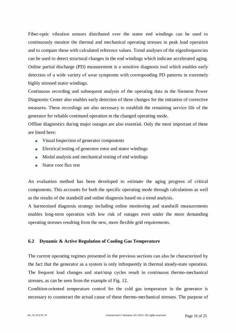
6.2 Dynamic & Active Regulation of Cooling Gas Temperature
The current operating regimes presented in the previous sections can also be characterized by
the fact that the generator as a system is only infrequently in thermal steady-state operation.
The frequent load changes and start/stop cycles result in continuous thermo-mechanical
stresses, as can be seen from the example of Fig. 12.
Condition-oriented temperature control for the cold gas temperature in the generator is
necessary to counteract the actual cause of these thermo-mechanical stresses. The purpose of

AL: N; ECCN: N Unrestricted © Siemens AG 2015. All rights reserved. Page 17 of 25
a cold gas temperature control of this type is to significantly reduce the temperature changes
in the individual generator components due to load changes by controlling the cold gas
temperature based on condition (e.g. as a function of apparent power output). Fig. 13 shows a
schematic of a non-regulated system which can be converted to a system with condition-
oriented dynamic control through the implementation of new hardware.
The development of an intelligent, dynamic control of the generator cooling system, which
ensures a significant reduction in stresses due to thermal cycles, provides the following
advantages:
Improved thermal operating mode of the generator as a thermo-mechanically sensitive
system
Seamless integration in the power plant as an overall system
Individual solution possibilities for existing plants
Fig. 23: Example of a simple cooling system without active temperature control in the power plant
Simple cooling water system without active control

AL: N; ECCN: N Unrestricted © Siemens AG 2015. All rights reserved. Page 18 of 25
Fig. 34: Example of an active/intelligent temperature control in the power plant
6.3 Advanced Stator End Winding Design for Direct Hydrogen-Cooled Stators
With targeted modernization measures, the more stringent requirements of the more flexible
electric power market and the new ENTSO-E Grid Codes with frequent and rapid load
changes (peak load operation) can be fulfilled even by older generators which were originally
designed for base load operation.
The accelerated exhaustion of service life due to the many load changes and the associated
increasing outage risk can be counteracted by the early measure of stator rewinding with a
stator winding which has been specially calculated and designed for peak load operation. The
newly designed end winding assembly has the features shown in Fig. 15 which enable axial
displacement on rapid heating and cooling of the copper conductors without compromising
transient short-circuit resistance [2].
Smoothing of stator winding temperature fluctuations with active control of generator cooling circuit

AL: N; ECCN: N Unrestricted © Siemens AG 2015. All rights reserved. Page 19 of 25
Fig. 15: New end winding design adapted for flexible peak load operation for backfitting (rewinding) of
generators with direct hydrogen cooling
The design of the stator winding bars can also be converted to the new operating mode with
frequent rapid load changes. Fig. 16 shows the configuration of the new stator winding in a
cross-sectional drawing of the slot. Internal potential grading (IPG) shifts the high-voltage
potential of the copper conductors to the high-voltage insulation, with the result that thermo-
mechanically induced insulation detachment from the copper conductors can no longer result
in high-voltage discharges in the resulting gap, which would reduce electrical service life.
Increasing the edge radius with the IPG profile strip homogenizes the electrical field in the
high-voltage insulation. This improves dielectric strength and hence the service life of the
insulation system [2].

AL: N; ECCN: N Unrestricted © Siemens AG 2015. All rights reserved. Page 20 of 25
Fig. 16: Inner corona protection (ICP) on direct H2-cooled stator winding for fast load changes in peak load
operation
The new winding design has the following advantages [2]:
Designed for continuous medium and peak-load operation with frequent rapid load changes
Suitable for modernization measures on old generators in the context of rewinding
Tolerant to transient thermal and electrical overloading which can occur as increased
current and voltage fluctuations in volatile transmission grids
Not sensitive to steep, high load ramps with many starts/stops necessary to stabilize electric
power grids with a significant fraction of renewable energy
The reduced maximum electrical edge field strength in the copper conductor and the
internal potential grading result in longer electrical service life of the high-voltage
insulation
6.4 Lifetime Extension Management of Old Generators
Service and maintenance measures must also be adapted to the new requirements in order to
render the generators suitable for the future demands
This transition from base load to medium or even peak load represents a new challenge for the
conventional power plants which have been in operation for many years. The experience-
based inspection cycles and the resulting inspection strategies must be reevaluated. The
ICP design acts as a shear plane for thermo-mechanical stresses generated by fast current increases due to load changes

AL: N; ECCN: N Unrestricted © Siemens AG 2015. All rights reserved. Page 21 of 25
empirically optimized combination of inspection measures on various power plant
components in common inspection and overhaul measures must be reassessed and additional
inspection outages or more extensive backfitting or retrofitting measures on the power plant
components must be accounted for in the new inspection and overhaul strategy. This results in
greater effort and rising costs in the operation of conventional power plants in volatile grids
with preferential feed from renewable energy sources.
These adaptations must be implemented in order to ensure the provision of a secure and
sustainably available power reserve from conventional power plants which is absolutely
necessary for the success of the transition to renewable energy.
A condition-based maintenance, refurbishment and replacement strategy is needed to reduce
the sudden outage risk for older generators. The first step should be an economic decision-
making process which evaluates operation and maintenance costs against risks of loss of
availability and efficiency of the generator. The following influencing factors should be
analyzed and weighted:
Actual and future operating regime of the unit (base - medium - peak load)
Past and planned maintenance strategy – e.g. condition-based maintenance
Offline diagnosis (number of inspections and tests during stand-still)
Existing and planned online monitoring systems with use of an OEM remote
diagnostic center for risk mitigation during service period
Knowledge of generator type-dependent risk components
Availability of strategic spare parts for fast repair
Planned availability rate of the unit and importance within generation assets of the
utility
Available investments for short-term component refurbishment and long-term life
time costs.
Based on this information, the utility could start a detailed residual life assessment study
together with the OEM to prepare the decision for possible lifetime extension of the
generator. Refurbishment or component replacement with the new design for higher stresses
will give the generator an increased lifetime with better performance under flexible grid
demands.
Life Time Extension (LTE) management of older and highly-stressed generators can be
summarized with the following five steps:
(1) Prepare residual lifetime and technical risk assessment study utility together with OEM

AL: N; ECCN: N Unrestricted © Siemens AG 2015. All rights reserved. Page 22 of 25
(2) Plan optimized maintenance activities based on financial risks (forced outage and degree
of damage) Predictive maintenance
(3) Make long-term refurbishment (identified components) or replacement decision based on
financial asset management
(4) Install online monitoring tools and a supervising remote diagnostic system for early
warning of incipient damage Sudden outage risk mitigation
(5) Plan risk-based predictive maintenance strategy depending on operational stress factor in
peak / medium / base load operation
7 Conclusion
To summarize, it can be stated that:
The new flexible grid demand has an impact on the generator as an overall system
with different degrees of advanced aging acceleration for individual components
Changed requirements and remaining uncertainty for the future increase in flexibility
must be considered in current generator development programs
Thermo mechanical stresses on generator components require enhanced load
dependent cooling technology, particularly at the stator winding
Special online monitoring systems and offline maintenance tools are needed for
inspection of generator components as early warning systems for weak points
A condition-based maintenance, refurbishment and replacement strategy is needed to
reduce the sudden outage risk for older generators
New maintenance concepts and service intervals are needed (e.g. VGB R 167).

AL: N; ECCN: N Unrestricted © Siemens AG 2015. All rights reserved. Page 23 of 25
8 References [1] Burger, B.: Electricity production from solar and wind energy in Germany 2014
Fraunhofer Institute for Solar Energy Systems ISE, Freiburg Dec 2014
[2] Dr.-Ing. Ana Joswig, Dr.-Ing. Thorsten Krol, Dipl.-Ing. Jürgen R. Weidner, Siemens AG:
Auswirkungen der neuen flexibleren Netzanforderungen auf die zukünftige Betriebs-
beanspruchung der Turbogeneratoren (VGB KELI 2014)
[3] Nicholas Muntz, Dr. rer. nat. Thorsten Krol, Siemens AG: The new Gas Turbine
Portfolio to meet the market requirements for Distributed Generation (Power Gen June
2015, Amsterdam)
[4] ENTSO-E Network Code for Requirements for Grid Connection Applicable to all
Generators, published by ENTSO-E AISBL, Brussels March 2013, Belgium
[5] Implementation Guideline for Network Code “Requirements for Grid Connection
Applicable to all Generators”, published by ENTSO-E AISBL, Brussels October 2013,
Belgium
[6] Geraerds, T.: The new European Network Codes on Electricity and their technical impact
on our power plants, VGB KELI 2014, Landshut, Germany
[7] Eurelectric und VGB: Draft ENTSO-E Network Codes on Requirements for Generators,
Meeting with DNV KEMA, Arnhem 23 April 2013

AL: N; ECCN: N Unrestricted © Siemens AG 2015. All rights reserved. Page 24 of 25
9 Disclaimer These documents contain forward-looking statements and information – that is, statements
related to future, not past, events. These statements may be identified either orally or in
writing by words as “expects”, “anticipates”, “intends”, “plans”, “believes”, “seeks”,
“estimates”, “will” or words of similar meaning. Such statements are based on our current
expectations and certain assumptions, and are, therefore, subject to certain risks and
uncertainties. A variety of factors, many of which are beyond Siemens’ control, affect its
operations, performance, business strategy and results and could cause the actual results,
performance or achievements of Siemens worldwide to be materially different from any
future results, performance or achievements that may be expressed or implied by such
forward-looking statements. For us, particular uncertainties arise, among others, from changes
in general economic and business conditions, changes in currency exchange rates and interest
rates, introduction of competing products or technologies by other companies, lack of
acceptance of new products or services by customers targeted by Siemens worldwide,
changes in business strategy and various other factors. More detailed information about
certain of these factors is contained in Siemens’ filings with the SEC, which are available on
the Siemens website, www.siemens.com and on the SEC’s website, www.sec.gov. Should one
or more of these risks or uncertainties materialize, or should underlying assumptions prove
incorrect, actual results may vary materially from those described in the relevant forward-
looking statement as anticipated, believed, estimated, expected, intended, planned or
projected. Siemens does not intend or assume any obligation to update or revise these
forward-looking statements in light of developments which differ from those anticipated.
Trademarks mentioned in these documents are the property of Siemens AG, its affiliates or
their respective owners.

AL: N; ECCN: N Unrestricted © Siemens AG 2015. All rights reserved. Page 25 of 25
Published by and copyright © 2015: Siemens AG Freyeslebenstrasse 1 91058 Erlangen, Germany
Siemens Energy, Inc. 4400 Alafaya Trail Orlando, FL 32826-2399, USA
For more information, please contact our Customer Support Center. Phone: +49 180/524 70 00 Fax: +49 180/524 24 71 (Charges depending on provider)
E-mail: [email protected]
All rights reserved. Trademarks mentioned in this document are the property of Siemens AG, its affiliates, or their respective owners.
Subject to change without prior notice. The information in this document contains general descriptions of the technical options available, which may not apply in all cases. The required technical options should therefore be specified in the contract..