impact of soil structure interaction on the seismic design of
TRANSCRIPT

Impact of Soil Structure Interaction on the Seismic
Design of Reinforced Concrete Buildings with Underground Stories G. Saad, F. Saddik & S. Najjar American University of Beirut, Lebanon
ABSTRACT: Current building codes lack explicit recommendations on how to simulate the seismic performance of high-rise buildings with multiple underground stories. Designers are typically basing their analyses on subjective engineering judgment and experience. Some model and analyse the buildings cropped at the ground floor level, others include a partial number of basement floors, while a few include all the underground floors. This paper studies the seismic behaviour of reinforced concrete buildings with multiple underground stories. It seeks to provide recommendations on the number or percentage of underground stories to be accounted for in the analysis of reinforced concrete shear wall buildings. A base-case where the buildings are modeled with a fixed condition at ground level is adopted, and then the number of basements is incrementally increased to investigate changes in performance. The Beirut local site conditions are used for the analysis. The base shear, inter-story shears and moments are evaluated in order to quantify the effects of soil structure interaction on the design process. Keywords: Soil Structure Interaction, Seismic Design, Reinforced Concrete Buildings 1. INTRODUCTION A controversial issue in the seismic analysis and design of buildings with multiple underground stories lies in incorporating the effects of these underground stories on the seismic response of these structures. Building codes lack recommendations concerning this controversy; thus, the designers are basing their analysis on approximations, engineering judgment and experience. Some model and analyze the building cropped at the ground floor level, others include a certain number of basement floors, while few include all the underground floors. This has been an active area of research throughout the past decade (Dutta and Roy, 2002, Dutta et al., 2004, Shakib, 2004, Naim et al., 2008, El Ganainy and El Naggar, 2009, Raychowdury 2010, Tabatabaeifar and Massumi, 2010). El Ganainy and El Naggar investigated the seismic performance of moment-resisting frame steel buildings with multiple underground stories. Their study was tailored for the governing site conditions in Vancouver, Canada, and the Beam-on-a-Nonlinear Winkler Foundation approach was used to simulate the important aspects of the nonlinear behaviour of the foundation and side soil. Raychowdhury also used a similar approach to study the response of low-rise steel moment resisting frame buildings. Tabatabaiefar and Matssumi (2010) used a 3D finite element model to simulate the effects of soil structure interaction on reinforced concrete moment resisting frames. While current research mainly aims at understanding the effects of soil structure interactions, this study has the ultimate goal of finding appropriate recommendations concerning the inclusion of underground stories in the modelling and analysis of reinforced concrete shear wall buildings and optimizing their design. The impacts of the building substructure on its seismic performance are gauged by explicitly incorporating the underground stories, basement walls, foundation and side soil in the structural analysis model. In accordance with the geotechnical map of Beirut, the soil types considered in modelling the subsurface conditions are assumed to consist of medium dense and very
dense sands. In addition, ground-shaking levels that are in line with Lebanon’s seismic hazard are used in the study. A sensitivity analysis is conducted by modelling the structure using the software SAP2000 (CSI, 2007) with the following varying parameters:
• Number of above ground stories • Number of underground stories • Subsurface soil conditions
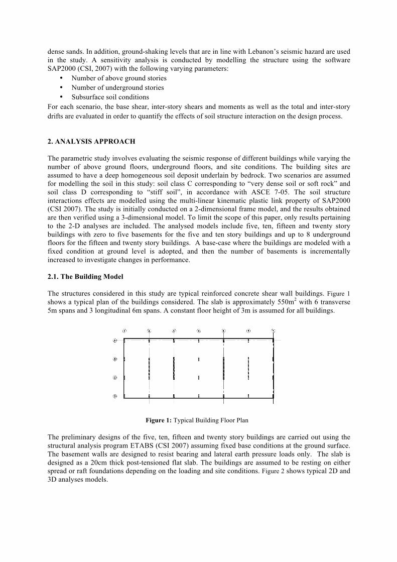
For each scenario, the base shear, inter-story shears and moments as well as the total and inter-story drifts are evaluated in order to quantify the effects of soil structure interaction on the design process. 2. ANALYSIS APPROACH The parametric study involves evaluating the seismic response of different buildings while varying the number of above ground floors, underground floors, and site conditions. The building sites are assumed to have a deep homogeneous soil deposit underlain by bedrock. Two scenarios are assumed for modelling the soil in this study: soil class C corresponding to “very dense soil or soft rock” and soil class D corresponding to “stiff soil”, in accordance with ASCE 7-05. The soil structure interactions effects are modelled using the multi-linear kinematic plastic link property of SAP2000 (CSI 2007). The study is initially conducted on a 2-dimensional frame model, and the results obtained are then verified using a 3-dimensional model. To limit the scope of this paper, only results pertaining to the 2-D analyses are included. The analysed models include five, ten, fifteen and twenty story buildings with zero to five basements for the five and ten story buildings and up to 8 underground floors for the fifteen and twenty story buildings. A base-case where the buildings are modeled with a fixed condition at ground level is adopted, and then the number of basements is incrementally increased to investigate changes in performance. 2.1. The Building Model The structures considered in this study are typical reinforced concrete shear wall buildings. Figure 1 shows a typical plan of the buildings considered. The slab is approximately 550m2 with 6 transverse 5m spans and 3 longitudinal 6m spans. A constant floor height of 3m is assumed for all buildings.
The preliminary designs of the five, ten, fifteen and twenty story buildings are carried out using the structural analysis program ETABS (CSI 2007) assuming fixed base conditions at the ground surface. The basement walls are designed to resist bearing and lateral earth pressure loads only. The slab is designed as a 20cm thick post-tensioned flat slab. The buildings are assumed to be resting on either spread or raft foundations depending on the loading and site conditions. Figure 2 shows typical 2D and 3D analyses models.
Figure 1: Typical Building Floor Plan

Figure 2: Typical 2D SAP2000 model (left) and 3D model (right) The construction materials used are selected based on their availability in the Lebanese market. It is assumed that concrete has an ultimate compressive strength f’c = 35MPa; the reinforcement steel has a yield strength fy = 420MPa, and a modulus of elasticity of 200GPa. The gravity loads assigned to the buildings are the own weights of the structural components including the reinforced concrete beams, columns, slabs and basement and shear walls. The weights of the non-structural components (e.g. cladding, tiling, partitions, finishing, etc.) are modelled as a superimposed uniform load equal to 4kN/m2. A uniformly distributed live load of 2kN/m2 is used for all residential areas and 3kN/m2 for parking zones as per the ASCE 7-05 load requirement criteria. 2.2. Soil Properties Table 1 presents the governing soil parameters for the different site classes used in the study. The parameters are estimated by correlating the ASCE site classification to the principles of soil mechanics. Table 1: Soil Parameters
Property/ Soil Type SC SD φ (friction angle) (degrees) 42 37 γ (unit weight) (kN/m3) 20 19 ν (poisson's ratio) 0.4 0.3 Vs (Shear wave velocity) (m/s) 500 275 Relative Density (%) 90 65 Go (initial shear modulus) (kPa) 510,000 146,500 Fa (site coefficient) (FEMA 356) 1 1 Sxs (design spectral acceleration at short period) 2 2 G/Go (FEMA 356 table 4-7) 0.6 0.1
2.2.1. Side Soil The side soil behavior is represented using p-y curves. P-y curves are force versus displacement functions that are generally used to model the reaction of the soil for applications involving laterally loaded piles. In this paper, P-y curves, as shown in Figure 3, are used to model the lateral earth pressure
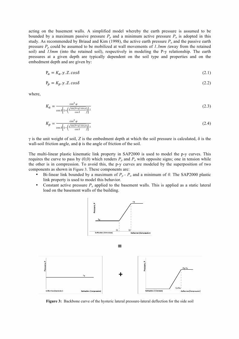
acting on the basement walls. A simplified model whereby the earth pressure is assumed to be bounded by a maximum passive pressure Pp and a minimum active pressure Pa is adopted in this study. As recommended by Briaud and Kim (1998), the active earth pressure Pa and the passive earth pressure Pp could be assumed to be mobilized at wall movements of 1.3mm (away from the retained soil) and 13mm (into the retained soil), respectively in modeling the P-y relationship. The earth pressures at a given depth are typically dependent on the soil type and properties and on the embedment depth and are given by:
P! = 𝐾! . 𝛾.𝑍. 𝑐𝑜𝑠𝛿 (2.1)
P! = 𝐾!. 𝛾.𝑍. 𝑐𝑜𝑠𝛿 (2.2) where,
𝐾! =cos2 𝜑
cos 𝛿 1+sin(𝛿+𝜑) sin𝜑
cos 𝛿 2 (2.3)
𝐾! =
cos2 𝜑
cos 𝛿 1−sin(𝛿+𝜑) sin𝜑
cos 𝛿 2 (2.4)
γ is the unit weight of soil, Z is the embedment depth at which the soil pressure is calculated, δ is the wall-soil friction angle, and ϕ is the angle of friction of the soil. The multi-linear plastic kinematic link property in SAP2000 is used to model the p-y curves. This requires the curve to pass by (0,0) which renders Pp and Pa with opposite signs; one in tension while the other is in compression. To avoid this, the p-y curves are modeled by the superposition of two components as shown in Figure 3. These components are:
• Bi-linear link bounded by a maximum of Pp - Pa and a minimum of 0. The SAP2000 plastic link property is used to model this behavior.
• Constant active pressure Pa applied to the basement walls. This is applied as a static lateral load on the basement walls of the building.
=
Figure 3: Backbone curve of the hysteric lateral pressure-lateral deflection for the side soil
+

2.2.2. Foundation Soil The foundation system of the buildings comprises of either a network of shallow spread footings or a raft foundation depending on the loading and site conditions. Two types of shallow footings are identified: one for interior columns and another for edge columns. The foundations of the basement walls are designed as strip footings. Shallow and strip footings are designed based on the Meyerhof’s bearing capacity and the elastic settlement theory criteria as outlined in Das 2007. The design is then checked for one-way and two-way shear failure according to ACI 318-08. The vertical, horizontal, and rotational elastic stiffness of the footings are calculated using the frequency independent formulas given in the FEMA 356 report. A set of 6 spring constants corresponding to the six degrees of freedom are calculated as a function of the footing dimensions and assigned to the model node of the respective footing. The raft foundation is designed to be rigid to minimize differential settlements. According to the ACI criteria, a raft foundation is considered rigid if the spacing between columns is less than 1.75/β, where β is a function of the raft dimensions, raft modulus of elasticity, and soil’s subgrade modulus. Based on this assumption, whenever the foundation system is a raft, the model is constrained against rotational degrees of freedom at the corresponding location. 2.3. Ground Motion There are no recorded ground motions in Lebanon. This lead researchers to seek earthquake records consistent with the seismic nature of the country (Harajli 1994, Huijer 2010). A time history consistent with the 1940 El Centro Earthquake is used in this study. The El Centro earthquake, Figure 4, is produced by the strike slip Imperial fault in the Southern California region. It has a magnitude of 6.9 on the Richter scale and an epicentral distance of 13Km. This time history excitation is selected for the following reasons (Huijer 2010):
• The capability of the Lebanese faults of producing earthquakes of equivalent magnitude and epicentral distances.
• The common characteristics that exist between the Imperial strike-slip fault and the Yammouneh fault, the most significant fault in Lebanon.
Figure 4: The 1940 El Centro Ground Motion
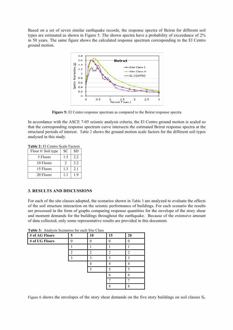
Based on a set of seven similar earthquake records, the response spectra of Beirut for different soil types are estimated as shown in Figure 5. The shown spectra have a probability of exceedance of 2% in 50 years. The same figure shows the calculated response spectrum corresponding to the El Centro ground motion.
Figure 5: El Centro response spectrum as compared to the Beirut response spectra In accordance with the ASCE 7-05 seismic analysis criteria, the El Centro ground motion is scaled so that the corresponding response spectrum curve intersects the estimated Beirut response spectra at the structural periods of interest. Table 2 shows the ground motion scale factors for the different soil types analysed in this study. Table 2: El Centro Scale Factors
Floor #/ Soil type SC SD 5 Floors 1.5 2.2
10 Floors 2 3.2 15 Floors 1.3 2.1 20 Floors 1.1 1.9
3. RESULTS AND DISCUSSIONS For each of the site classes adopted, the scenarios shown in Table 3 are analyzed to evaluate the effects of the soil structure interaction on the seismic performance of buildings. For each scenario the results are processed in the form of graphs comparing response quantities for the envelope of the story shear and moment demands for the buildings throughout the earthquake. Because of the extensive amount of data collected, only some representative results are provided in this document. Table 3: Analysis Scenarios for each Site Class # of AG Floors 5 10 15 20 # of UG Floors 0 0 0 0 1 1 1 1 2 2 2 2 3 3 3 3
4 4 4
5 5 5
6 6
7 7
8 8
Figure 6 shows the envelopes of the story shear demands on the five story buildings on soil classes SC

and SD respectively. These demands are for the 1940 El Centro earthquake scaled by a factor of 1.5 for SC and 2.2 for SD. Each plot shows three sets of results: the set labeled “fixed” corresponds to the building cropped and fixed at the ground level; the set labeled “0 bas” corresponds to the same building resting on spread footings; and the “3 bas” corresponds to the same building with three underground basements and resting on spread footings.
Figure 6: Story Shear demands on the five-story building; Soil Class SC (left) and Soil Class SD (right)
Figure 7 shows the envelopes of the story moment demands on the five story buildings on soil classes SC and SD respectively. The preliminary results shown in Figures 6 and 7 indicate that the soil structure interaction plays a significant role in increasing the story shear and moment demands for relatively low-rise buildings. This effect is more pronounced in buildings resting on softer soils.
Figure 7: Story Moment demands on the five-story building; Soil Class SC (left) and Soil Class SD (right) Figure 8 presents the envelopes of the story shear and moment demands for the first 5 floors of a 10 story building on soil class SC. The results show that the soil structure interaction effects are less significant in this case. Similar results were observed in previous studies (Dutta 2004).
0"
1"
2"
3"
4"
5"
(8000" (6000" (4000" (2000" 0" 2000" 4000" 6000" 8000"
Story"Level""
Story"Shear"(KN)"
fixed%0%bas%3%bas%
0"
1"
2"
3"
4"
5"
(8000" (6000" (4000" (2000" 0" 2000" 4000" 6000" 8000"
Story"Level""
Story"Shear"(KN)"
fixed%
0%bas%
3%bas%
0"
1"
2"
3"
4"
5"
(14000" (9000" (4000" 1000" 6000" 11000"
Story"Level""
Story"Moment"(KN(m)"
fixed%0%bas%3%bas%
0"
1"
2"
3"
4"
5"
(14000" (9000" (4000" 1000" 6000" 11000"
Story"Level""
Story"Moment"(KN(m)"
fixed%0%bas%3%bas%
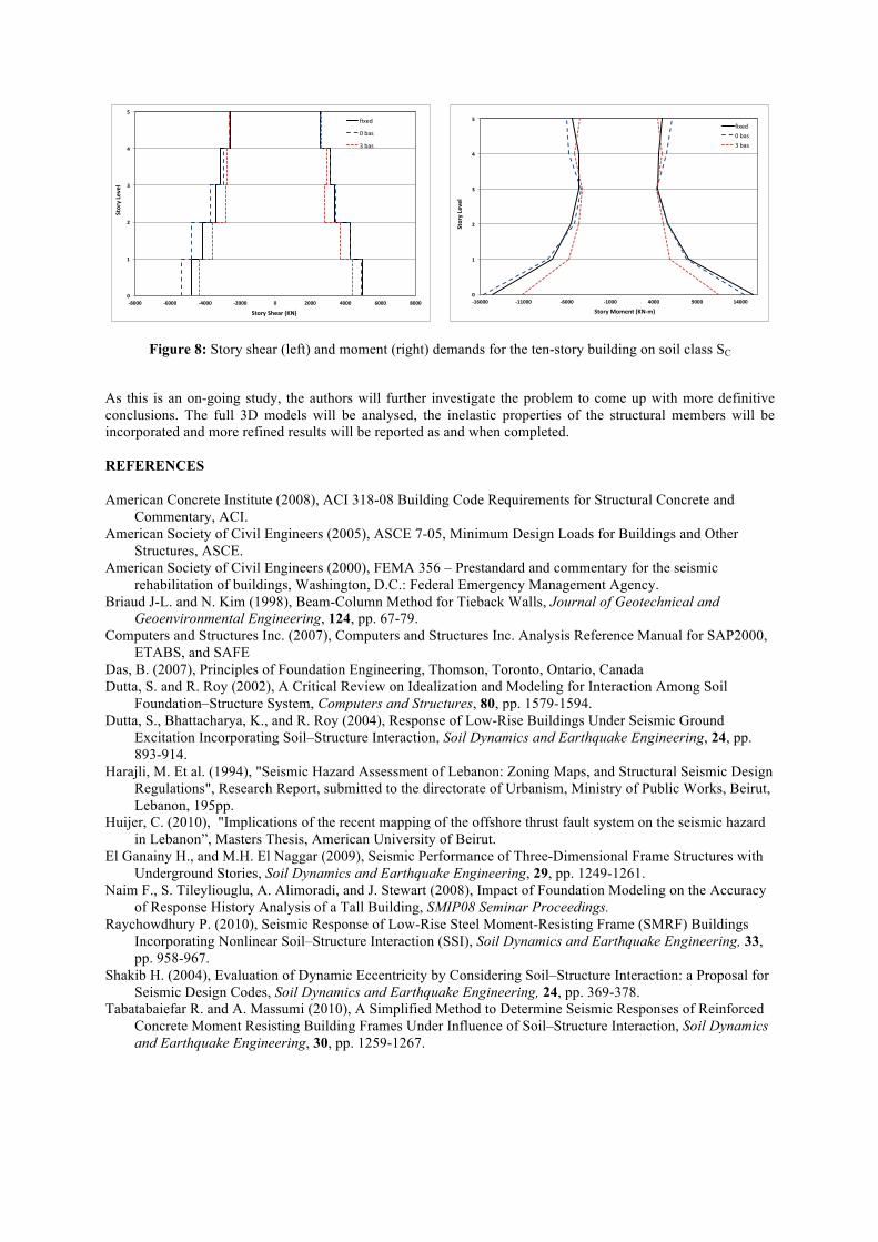
Figure 8: Story shear (left) and moment (right) demands for the ten-story building on soil class SC
As this is an on-going study, the authors will further investigate the problem to come up with more definitive conclusions. The full 3D models will be analysed, the inelastic properties of the structural members will be incorporated and more refined results will be reported as and when completed. REFERENCES American Concrete Institute (2008), ACI 318-08 Building Code Requirements for Structural Concrete and
Commentary, ACI. American Society of Civil Engineers (2005), ASCE 7-05, Minimum Design Loads for Buildings and Other
Structures, ASCE. American Society of Civil Engineers (2000), FEMA 356 – Prestandard and commentary for the seismic
rehabilitation of buildings, Washington, D.C.: Federal Emergency Management Agency. Briaud J-L. and N. Kim (1998), Beam-Column Method for Tieback Walls, Journal of Geotechnical and
Geoenvironmental Engineering, 124, pp. 67-79. Computers and Structures Inc. (2007), Computers and Structures Inc. Analysis Reference Manual for SAP2000,
ETABS, and SAFE Das, B. (2007), Principles of Foundation Engineering, Thomson, Toronto, Ontario, Canada Dutta, S. and R. Roy (2002), A Critical Review on Idealization and Modeling for Interaction Among Soil
Foundation–Structure System, Computers and Structures, 80, pp. 1579-1594. Dutta, S., Bhattacharya, K., and R. Roy (2004), Response of Low-Rise Buildings Under Seismic Ground
Excitation Incorporating Soil–Structure Interaction, Soil Dynamics and Earthquake Engineering, 24, pp. 893-914.
Harajli, M. Et al. (1994), "Seismic Hazard Assessment of Lebanon: Zoning Maps, and Structural Seismic Design Regulations", Research Report, submitted to the directorate of Urbanism, Ministry of Public Works, Beirut, Lebanon, 195pp.
Huijer, C. (2010), "Implications of the recent mapping of the offshore thrust fault system on the seismic hazard in Lebanon”, Masters Thesis, American University of Beirut.
El Ganainy H., and M.H. El Naggar (2009), Seismic Performance of Three-Dimensional Frame Structures with Underground Stories, Soil Dynamics and Earthquake Engineering, 29, pp. 1249-1261.
Naim F., S. Tileyliouglu, A. Alimoradi, and J. Stewart (2008), Impact of Foundation Modeling on the Accuracy of Response History Analysis of a Tall Building, SMIP08 Seminar Proceedings.
Raychowdhury P. (2010), Seismic Response of Low-Rise Steel Moment-Resisting Frame (SMRF) Buildings Incorporating Nonlinear Soil–Structure Interaction (SSI), Soil Dynamics and Earthquake Engineering, 33, pp. 958-967.
Shakib H. (2004), Evaluation of Dynamic Eccentricity by Considering Soil–Structure Interaction: a Proposal for Seismic Design Codes, Soil Dynamics and Earthquake Engineering, 24, pp. 369-378.
Tabatabaiefar R. and A. Massumi (2010), A Simplified Method to Determine Seismic Responses of Reinforced Concrete Moment Resisting Building Frames Under Influence of Soil–Structure Interaction, Soil Dynamics and Earthquake Engineering, 30, pp. 1259-1267.
0"
1"
2"
3"
4"
5"
(8000" (6000" (4000" (2000" 0" 2000" 4000" 6000" 8000"
Story"Level""
Story"Shear"(KN)"
fixed%
0%bas%
3%bas%
0"
1"
2"
3"
4"
5"
(16000" (11000" (6000" (1000" 4000" 9000" 14000"
Story"Level""
Story"Moment"(KN(m)"
fixed%0%bas%3%bas%