impact of the ship generating sets’ power factor on …2017.icmd.cz/proceedings/78_icmd.pdf ·...
TRANSCRIPT
58th ICMD 2017
6 - 8 September 2017, Prague, Czech Republic
IMPACT OF THE SHIP GENERATING SETS’ POWER FACTOR ON THE
DETERMINATION OF THE LOAD FACTOR IN AUXILIARY ENGINE
Dariusz TARNAPOWICZ1, Zbigniew MATUSZAK2
1 Maritime University of Szczecin, Poland, e-mail: [email protected] 2Maritime University of Szczecin, Poland, e-mail: [email protected].
Abstract
In order to evaluate the work of marine power plants, it is necessary, among other things, to determine
the load factor in auxiliary engines. The load factor’s value is usually used in analyzes of economical
exploitation of the power plant, and also in the ecological aspect – limitation of exhaust emissions by
auxiliary engines. In many scientific reports and publications, the load factor is determined directly
from measurements of loads in generators (active power). The efficiency of the generator is not taken
into account. In this article, the authors present the impact of the nature of the generator’s load on its
efficiency, and hence on the determination of the load factor in auxiliary engines.
Key words: load factor of auxiliary engines; power factor; efficiency of synchronous generator.
INTRODUCTION
Statistically, the most commonly used in shipbuilding industry methods of generating electricity on
ships are autonomous generating sets consisting of combustion auxiliary engines (AE) and self-excited
synchronous generators (G).
For the assessment of the operation of marine power plants, for example in terms of environmental
protection or optimization of fuel consumption, it is crucial to determine the load factor for auxiliary
engines (LFAE). In the majority of studies, the load factor of auxiliary engines is a direct correlation with
active power of the generator’s load read on meters or recorders e.g.:(U.S. EPA, 2009). In this case, the
excess power of auxiliary engines with respect to generators and the generator’s efficiency are not taken
into account. The importance of the AE load factor in terms of economy, but also ecology, is perfectly
presented by the characteristics of the specific fuel consumption (SFC) depending on the load factor
(LFAE) (Tarnapowicz, Borkowski, 2016).
Fig. 1. Dependence of SFC in the function of LFAE load factor (Tarnapowicz, Borkowski, 2016)
Based on the presented characteristics (Figure 1), it is possible to optimize the auxiliary engine’s oper-
ation – achieving a minimum SFC. This optimization is carried out especially during the parallel oper-
ation of generating sets in the so-called asymmetrical work. The parallel work is performed on the ship
in order to provide power reserve. Then we can deal with symmetrical work (symmetrical load of gen-
erating sets with minimum SFC). The second reason for parallel work of generating sets is to ensure
power supply reliability. In this case, low load factor of auxiliary engines (LFAE) would cause a high
398

58th ICMD 2017
6 - 8 September 2017, Prague, Czech Republic
SFC. In order to optimize the work of generating sets, an asymmetric operation is possible (asymmetric
load of generating sets).
MATERIALS AND METHODS
Load factor of generating sets.
The load factor of auxiliary engines LFAE that takes into account the excess power of the engine and the
efficiency of generators demonstrates the following relation (Nicewicz, Sosiński, Tarnapowicz, 2014):
𝑳𝑭𝑨𝑬 =𝑳𝑭𝑮𝑺
𝜼𝑮∙𝜶𝑵𝑴 (1)
where:
LFGS – marine generating set (generator) load factor,
G – generator‘s efficiency,
αNM – excess power factor of the auxiliary engine to the generator.
Factors of the excess power of the main engine in relation to the generator αNM vary depending to the
type of ship and the year of construction. On the basis of researches conducted by the authors, it can be
concluded that the smallest values of factors were recorded on ships built after 2000. This leads to the
conclusion that the significance of the factor αNM for determination of LFAE is smaller for newly built
vessels. A summary of αNM values on selected ships is shown in Table 1(Nicewicz, Tarnapowicz, 2012).
Tab. 1 excess power factor of the auxiliary engine to the generator on the test ships
Type of ship Year of
construction
αNM
container ship 2005 1,05
container ship 1999 1,40
container ship 2001 1,05
container ship 2003 1,06
container ship 1982 1,21
semi-container ship 1986 1,62
bulk carrier 1993 1,60
bulk carrier 2003 1,10
bulk carrier 2000 1,09
The second feature taken into account in the formula (1) is the generator’s efficiency. The efficiency of
generator depends on several factors. The specification of synchronous generators includes dependences
between the efficiency and the generator’s load (ABB, 2012). At low loads of generators, the efficiency
decreases. The second characteristic that affects the efficiency is the power of generators. Based on the
analysis of the above-mentioned specification for various powers of generators, it can be stated that the
efficiency of generators increases along with the increase of power (Tarnapowicz, Borkowski, 2016).
The impact of the load on the generator’s efficiency is very rarely analyzed. As already mentioned, the
load of marine generators has a resistive-inductive nature. The power factor (cos) can range from 0 to
1.Figure 2 presents the dependence of the generator’s efficiency taking into account the nature of the
load (generator with a power of 2545 kVA). Characteristics are prepared on the basis of specification
for the selected generator. This feature shows a high dependence between the generator and the power
factor (power factor - cos. For small power factors, the generator’s efficiency decreases by a few
percent.
399

58th ICMD 2017
6 - 8 September 2017, Prague, Czech Republic
Fig. 2. The efficiency of the generator, depending on the power factor
An electrical ship network is a “soft” network. Powers of individual receivers are comparable to the
power of the generating set. The main receivers are electric squirrel-cage motors. Their power changes
along with the motor’s load (cos). These motors are often underpowered (with a low power factor).
Then the efficiency of the generator is lower.
The greatest differences in the nature of generating sets’ load can be observed in the parallel operation.
According to the rules of qualifying societies, the distribution of active and passive powers between
working in parallel generating sets must be uniform (with the same nominal powers of sets). In practice,
this situation does not always occur. Controllers of the auxiliary engines’ rotations are responsible for
the distribution of active powers. On the other hand, the distribution of passive powers (the nature of the
generators’ load) is controlled by voltage regulators for generators – their static characteristics (U=f (Q)
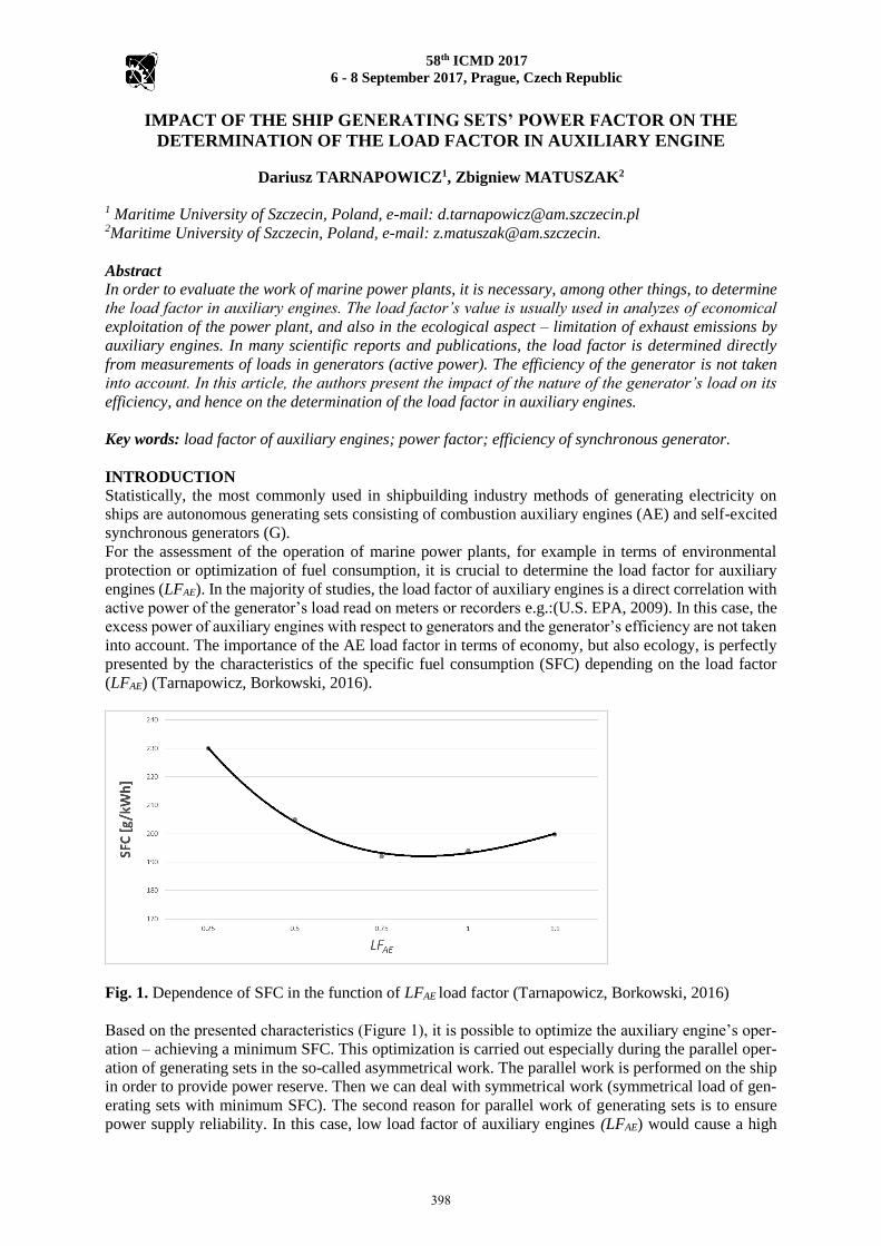
where U – generator’s load voltage, Q – Load of the generator with passive power). The vector diagram
of synchronous generators (working in parallel in case of equal loads with active powers and different
loads with passive power) is presented in Figure 3. It was made on the basis of equations (2):
xIRI1r1111 UUUXIjRIUE
xIRI2r2222 UUUXIjRIUE (2)
where:
E1, E2 - SEM induced in the winding of an armature during the generators’ loading
U1, U2 – voltage during the load of generators
I1, I2 – generator load currents,
R – resistance of the armature’s winding
Xr – reactance for the diffusion of the armature’s winding
82
84
86
88
90
92
94
96
98
0,4 0,6 0,8 1
[%
]
cos
Generator Load 25% Generator Load 50%
400
58th ICMD 2017
6 - 8 September 2017, Prague, Czech Republic
2
1
1I 2I
2U1U
a1I
r2I
a2I
r1I
I RU
I xU I xU
I RU
1E 2E
Fig. 3. Phasors for generators in parallel operation at different load of generators with passive power
(different cos of generators).
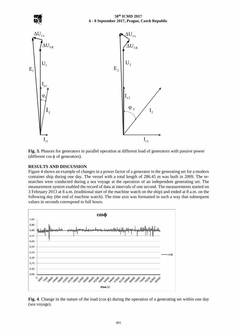
RESULTS AND DISCUSSION Figure 4 shows an example of changes in a power factor of a generator in the generating set for a modern
container ship during one day. The vessel with a total length of 286.45 m was built in 2009. The re-
searches were conducted during a sea voyage at the operation of an independent generating set. The
measurement system enabled the record of data at intervals of one second. The measurements started on
3 February 2013 at 8 a.m. (traditional start of the machine watch on the ship) and ended at 8 a.m. on the
following day (the end of machine watch). The time axis was formatted in such a way that subsequent
values in seconds correspond to full hours.
Fig. 4. Change in the nature of the load (cos ) during the operation of a generating set within one day
(sea voyage).
401
58th ICMD 2017
6 - 8 September 2017, Prague, Czech Republic
During the operation of a single generating set on the selected vessel, the power factor (cos ) changed
in the range from 0.62 to 0.92. In other cases, changes (cos ) may be even greater.
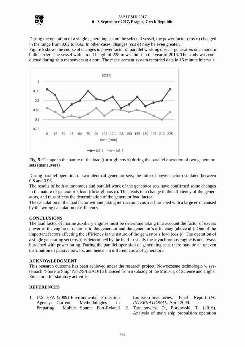
Figure 5 shows the course of changes in power factor of parallel working diesel - generators on a modern
bulk carrier. The vessel with a total length of 228 m was built in the year of 2013. The study was con-
ducted during ship maneuvers at a port. The measurement system recorded data in 15 minute intervals.
Fig. 5. Change in the nature of the load (through cos ) during the parallel operation of two generator
sets (maneuvers)
During parallel operation of two identical generator sets, the ratio of power factor oscillated between
0.8 and 0.96.
The results of both autonomous and parallel work of the generator sets have confirmed some changes
in the nature of generator’s load (through cos ). This leads to a change in the efficiency of the gener-
ators, and thus affects the determination of the generator load factor.
The calculation of the load factor without taking into account cos is burdened with a large error caused
by the wrong calculation of efficiency.
CONCLUSIONS The load factor of marine auxiliary engines must be determine taking into account the factor of excess
power of the engine in relations to the generator and the generator’s efficiency (above all). One of the
important factors affecting the efficiency is the nature of the generator’s load (cos ). The operation of
a single generating set (cos ) is determined by the load – usually the asynchronous engine is not always
burdened with power rating. During the parallel operation of generating sets, there may be an uneven
distribution of passive powers, and hence – a different cos of generators.
ACKNOWLEDGMENT
This research outcome has been achieved under the research project: Nowoczesne technologie w sys-
temach "Shore to Ship" No 2/S/IEiAO/16 financed from a subsidy of the Ministry of Science and Higher
Education for statutory activities
REFERENCES
1. U.S. EPA (2009) Environmental Protection
Agency: Current Methodologies in
Preparing Mobile Source Port-Related
Emission Inventories. Final Report. IFC
INTERNATIONAL. April 2009.
2. Tarnapowicz, D., Borkowski, T. (2016).
Analysis of main ship propulsion operation
0,75
0,8
0,85
0,9
0,95
1
0 15 30 45 60 75 90 105 120 135 150 165 180 195 210 225
time [min]
cos
DG-1 DG-2
402

58th ICMD 2017
6 - 8 September 2017, Prague, Czech Republic
with shaft generator. 57th International
Conference of Machine Design Departments
(ICMD), 2016 p 287-292
3. Nicewicz, G., Sosinski, M., Tarnapowicz, D.
(2014) Identification of power factor in
marine electrical grid. Geoconference on
energy and clean technologies, vol II.Book
Series: International Multidisciplinary
Scientific GeoConference-SGEM, 2014 (pp.
391-398).
4. Nicewicz, G., Tarnapowicz D. (2012)
Assessment of marine auxiliary engines load
factor in ports. Management Systems in
Production Engineering . No 3(7), 2012 p 12-
17
5. ABB. (2012): Low Voltage Synchronous
Generators for Industrial Applications,
Technical Specfcations AMG2 2012,
http://www.abb.com/product/2012.
Corresponding author:
Dariusz Tarnapowicz, Ph.D.Eng, Faculty of Marine Engineering, Institute of Marine Electrical
Engineering and Vessel Automation, Maritime University in Szczecin, 70-500 Szczecin, Poland, and
phone: 091-4809460, e-mail: [email protected]
Zbigniew Matuszak Prof. Eng, Faculty of Marine Engineering, Institute of Marine Propulsion Plants
Operation, Maritime University in Szczecin, 70-500 Szczecin, Poland, phone: 091-4809414, e-mail:
403