impact users manualimpact.sourceforge.net/manual_users/users.pdf · a good java engine is the sun...
TRANSCRIPT

Impact Users Manual
Table of Contents Impact Users Manual........................................................................................................................................1
Installation..............................................................................................................................................1 Prerequisites...............................................................................................................................1 Java_engine................................................................................................................................1 Processor....................................................................................................................................2
Solving problems with impact.................................................................................................................2Creating the indata file................................................................................................................2Solving........................................................................................................................................3Reading the results......................................................................................................................3
Contact handling in Impact.....................................................................................................................4Fembic Indata Format..............................................................................................................................5
Block Structure...........................................................................................................................5Commands..................................................................................................................................5
Other Indata and Outdata Formats.........................................................................................................35
Impact Users Manual
i

Impact Users ManualThis chapter is intended for the user more than the programmer. Reference for the Fembic indata program isalso included
Installation
Impact is a Java program which means that there is no compilation of sourcecode or similar to be done.However, there are some programs you need to install to be able to run Impact and to see the results.
Start by downloading the program files of impact from http://sourceforge.net/projects/impact
The file is a .zip file and must be untarred using the command tar −xvf filename.zip if you arerunning Linux. For Windows users the Winzip program will handle the expansion.
You will now have a directory for impact (highly originally called impact) where some files and directorieswill reside. They should be:
README• jama (dir) − The directory containing classes for matrix algebra• run (dir) − All the source code for Impact• Impact.gid (dir) − Configuration files for the GID pre/post processor• manual_Users (dir) − Users manual• manual_Programmers (dir) − Programmers manual and program installation• examples (dir) − All the example problems for Impact (.in)•
Prerequisites
To get Impact working you need:
A Java engine1. A Pre− and Postprocessor (optional but recommended)2.
Java_engine
A good Java engine is the Sun version which can be found at http://java.sun.com/j2se/1.4/download.html. Youcan take either the Runtime environment or the Software Development Kit.
There are several alternative Java engines. IBM has one which is very fast and is also recommended.
After installation, you can run the solver by going to the Impact directory (cd Impact) and then writing javarun.Impact examples/xxxxx.in where xxxxx is the name of your indatafile that you want to runwith the solver.
Impact will create two outdatafiles:
xxxxx.in.flavia.res•
Impact Users Manual 1

xxxxx.in.flavia.msh•
These files can be read by the GID pre−and postprocessor.
Processor
The recommended pre and postprocessor is GID. It is freely available as a limited edition. You will need todownload a version later than 6.2.0d since Impact uses features that are currently being implemented. You candownload GID from http://gid.cimne.upc.es
This is how you should set up and use GID for Preprocessing:
Run the installation file for GID and install the program.1. If you haven't installed Impact, proceed to do this.2. Look in the GID directory for a subdirectory called problemtypes and go there3. Make a new subdirectory called Impact4. Now copy the directory Impact.gid from where you installed Impact, making sure all files come withit
5.
The directory structure should now be GiD/problemtypes/Impact/Impact.gid/some files6. If you now start GiD, you should find Impact as an option under the DATA menu.7. GiD can now export indata files to Impact via the File−>Export−>CalculationFile menu8.
Impact also has a built in pre− and postprocessor which is under development. They are accessable from theImpactGUI.
Solving problems with impact
The solution process is made in three stages:
Creation of a model using a pre−processor or direct writing of the Fembic indata file1. Solution using the Impact program2. Presentation of the results using a post−processor and the result files from the solution3.
It is simplest to run Impact and the built in pre− and postprocessors from the GUI. To do that, just run theImpactGUI.bat file in this directory if you are a Windows user or make the ImpactGUI.sh runnable (chmod777 ImpactGUI.sh) and run that with ./ImpactGUI if you are a Linux/Unix/Mac user. Alternatively, just writebash ImpactGUI.sh to start.
Creating the indata file
The model can be created by the help of a pre−processor. A good one is called GID and is freely available forsmall models. it can be downloaded from here in versions for both unix and windows. Be sure to get a versionhigher than 6.2.0 due to advanced features used by Impact.
After installation of GID, you should copy the directory Impact/Impact and all its contents into the GIDsubdirectory called GID/problemfiles. This will install an extra option on the GID preprocessor menu andconfigure GID for Impact file format.
cp −r homedirectory/Impact/Impact /homes/myuser/GID7_0/problemtypes/
Impact Users Manual
Processor 2

Before starting to create models with GID, you should set GID in the Impact mode so that your model will betailored for Impact. This is done by selecting Data −> Problem type −> Impact −> Impact. This will give youa range of options under the Data menu which you can use to set material, boundary conditions etc.
After the model is created, it should be exported to a file. This is preferably done using the File −> Export −>Calculation file feature. It is of course also possible to write the complete file by hand using a favourite ASCIIeditor. The syntax of a Fembic file is explained in a later chapter.
Summary of how you should use GID for Pre−processing (creating models for Impact)
Start by selecting Impact as your solver by Data−>Problemtype−>Impact−>Impact1. Fill in the problem datas under Data−>Problem Data−>...2. Create a model and mesh it (read the GiD manual for how to do this)3. Set materials on all elements using Data−>Materials4. Set boundary conditions on the nodes using Data−>Conditions5. You can now export the indata file via Files−>Export−>Calculation file6.
Solving
The solution of the problem is initiated from the GUI or by writing java run.Impact file at the commandprompt, where file is the name of the indata file. In the case of a Fembic file, make sure it ends with .inbecause otherwise Impact will not recognise the format. It is also important that you are placed in the impactdirectory at the time of execution. A java engine must also be installed on your system before execution.
If you are running some of the example problems supplied, you need to add the path to the examplesdirectory. The syntax then becomes: java run.Impact examples/file where file applies as above.
If all goes well, you should now see the indata file being parsed by impact and the solution process initiated.Each time results are written, a notice will be written to the screen and you will see that execution is inprogress. A solution can take considerable time, so be patient.
Reading the results
The results are printed to the flavia.res and flavia.msh files. They will end up in the same directory as yoursourcefile. These are tailor made for the GID and the built in post processor.
Start by firing up GID and switch to post processing mode. Next read in the result file flavia.res. The mesh(flavia.msh) file will be read automatically. You should now see the model on the screen.
Press ctrl−d to set the timestep for deformation. Go from the top of the menu, starting by selectingdeformation and then time analysis. Select timestep 0, magnification factor 1.0 and then press apply.
Next press ctrl−v and select the results , time analysis and contour fill. Finally, select gausspointstress andapply.
Finally, press ctrl−m. You should now see the results as an animation. There are plenty of ways to view yourresults, but I refer to the GID users manual for that.
Summary of how you should use GiD for Post−processing (looking at the results)
Impact Users Manual
Solving 3

Fire up GID and switch to post−processing mode.1. Open the xxxxx.in.flavia.res file. If all goes well, you should be able to see your model.2. Press ctrl−d to set the timestep for deformation.3. Go from the top of the menu, starting by selecting deformation and then time analysis.4. Select timestep 0, magnification factor 1.0 and then press apply.5. Next press ctrl−v and select the results , time analysis and contour fill.6. Finally, select gausspointstress and apply.7. Next press ctrl−m to get a nice animation!8.
Alternatively, the built in postprocessor is directly accessable from the GUI. Just open the resultfile and selectthe time you want from the left column and you should see the model. Rotation, moving and zooming is doneby holding down any of the mouse buttons while moving the mouse.
Contact handling in Impact
Contacts in impact are handled by two element types:
Contact_Triangle (CT)• Contact_Line (CL)•
The CT is used to sense contact between nodes and surfaces and the CL senses contact against other CLelements. Together, these two elements can be used to enable contact detection for most cases and models.Both of them are classified as elements which means that they can directly be part of a model mesh as allelements. The user can for example model a wall or a complex rigid contact surface with them.
Since they only have the sole purpose of sensing contact, the have no stiffness at all. This means that if theyare used on their own in the model, the nodes connecting them should be fixed by constraints to prevent themfrom drifting when in contact. It also means that the user can use them in combination with ordinary elementsto provide contact sensing where this is not default.
One example where this is useful is when a body has been meshed using solid elements, for example anengine block in a car. This body can then be "dressed" on the outside with a second mesh of contact elementsto provide the contact sensitivity against other elements in the car. Any contact sensing inside the engineblock is not needed and valuable calculation time can then be saved with this approach.
Some elements have contact sensing as default. Examples of these are:
Shell_C0_3• Shell_BT_4• Rod_2• Beam_2•
When any of these elements is created, one or several contact elements are created by default. These areembedded inside the element and share the element nodes. The rod and beam elements use the Contact_Lineelement to sense contact. The Shell elements use the Contact_Triangle element to sense contact against thesurface and optionally Contact_Line elements at the edges to sense contact against other edges.
The contact elements drain quite a bit of computing resources and as the number of elements increase, so doesthe amount of computing power since the increase is more than linear. Therefore, some of the elements haveoptions to reduce the contact resolution. This means that the contact sensing will be less accurate during large
Impact Users Manual
Contact handling in Impact 4

deformation of the elements, but the solution will run faster. For this reason, contact sensing has also not beenimplemented in the solid elements since the user can best minimise the amount of calculations needed, bydistributing the contact element where they are needed.
The details of how contact sensing is implemented is explained in the programming manual.
Fembic Indata Format
The fembic indata format is the default indata format for Impact. It is designed to be simple to read andunderstand, and is written in free format which means that you can type as you wish and do not have to putdata at specific locations in the file. A file which is written in Fembic should have a name which ends with .inand be in ASCII format.
Comments may be included on any line but must be preceded by a # character. Every text written behind thissign will be ignored and the parser will continue on the next line instead.
The General syntax for this manual is that letters in bold are required input for the command. Input in normalwriting are optional.
Block Structure
A fembic file is structured in blocks. Each block starts with a keyword, followed by data related to that block.The blocks can come in any order and may be repeated. A block must start on a new line using any of thekeywords. Each keyword and the related data will now be described.
Commands
Command ElementsBlock Elements
Description The elements that make up the finite element model are defined within thisblock. Only one type of elements can be defined within each block.
Syntax Elements of Type eltype
Options eltype Any type of element: Rod_2, Beam_2, Solid_Iso_6,Shell_BT_4, Contact_Triangle
Example Elements of Type Shell_BT_4
See also Rod_2, Beam, Solid_Iso_6, Shell_BT_4, Shell_C0_3
Impact Users Manual
Fembic Indata Format 5

Command Beam_2Block Elements
Description This is a simple Beam element which means that it will transfer moment andalso take node rotation into account. The cross section is assumed solidcircular.
Syntax nr nodes = [node1,node2] D=diameter material= elmaterial
Options nr The element number. Must be a unique number in the model,i.e. another element cannot have the same number.
node1,2,.. The number of the first node etc.
diameter the cross section diameter of the Beam. The cross section issolid circular.
elmaterial The name of the material that the Beam element uses. Thisname must be defined under the material block.
Example 1 nodes = [23,24] D = 4.73 material = steel
See also Elements, Materials, Nodes
Impact Users Manual
Fembic Indata Format 6
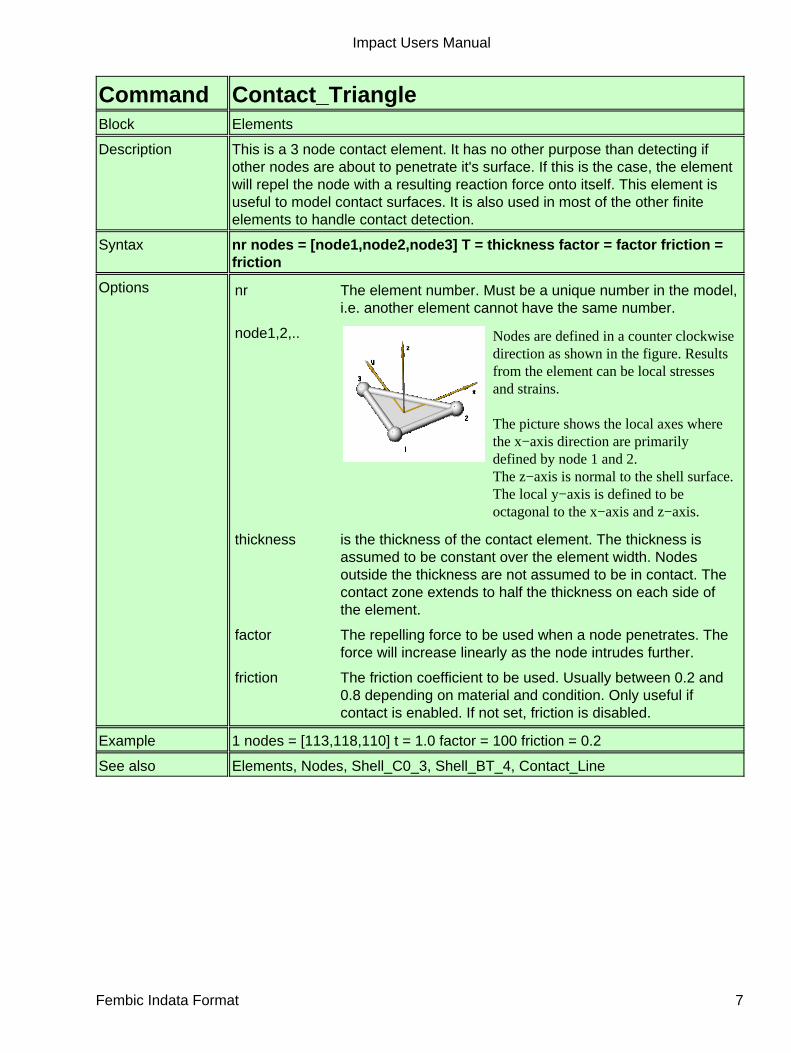
Command Contact_TriangleBlock Elements
Description This is a 3 node contact element. It has no other purpose than detecting ifother nodes are about to penetrate it's surface. If this is the case, the elementwill repel the node with a resulting reaction force onto itself. This element isuseful to model contact surfaces. It is also used in most of the other finiteelements to handle contact detection.
Syntax nr nodes = [node1,node2,node3] T = thickness factor = factor friction =friction
Options nr The element number. Must be a unique number in the model,i.e. another element cannot have the same number.
node1,2,.. Nodes are defined in a counter clockwisedirection as shown in the figure. Resultsfrom the element can be local stressesand strains.
The picture shows the local axes wherethe x−axis direction are primarilydefined by node 1 and 2.The z−axis is normal to the shell surface.The local y−axis is defined to beoctagonal to the x−axis and z−axis.
thickness is the thickness of the contact element. The thickness isassumed to be constant over the element width. Nodesoutside the thickness are not assumed to be in contact. Thecontact zone extends to half the thickness on each side ofthe element.
factor The repelling force to be used when a node penetrates. Theforce will increase linearly as the node intrudes further.
friction The friction coefficient to be used. Usually between 0.2 and0.8 depending on material and condition. Only useful ifcontact is enabled. If not set, friction is disabled.
Example 1 nodes = [113,118,110] t = 1.0 factor = 100 friction = 0.2
See also Elements, Nodes, Shell_C0_3, Shell_BT_4, Contact_Line
Impact Users Manual
Fembic Indata Format 7

Command Contact_LineBlock Elements
Description This element is a two node contact element of a line segment. The elementwill provide contact sensitivity within the diameter of the line. Also ends aredetected within the radius. Contact is sensed against nodes and othercontact_line elements.
Syntax nr nodes = [node1,node2] D=diameter factor = c_factor contact = c_type
Options nr The element number. Must be a unique number in the model,i.e. another element cannot have the same number.
node1,2,.. The number of the first node etc.
diameter the cross section diameter of the element. The cross sectionis solid circular.
c_factor The contact factor. This is the reaction force at fullpenetration of contact node. If nothing is specified, default is10.
c_type Contact type. Can be OFF to disable contact. Default contacttype is BASIC which means that contact sensing is enabled.
Example 1 nodes = [23,24] D = 4.73
See also Elements, Nodes, Shell_C0_3, Shell_BT_4, Contact_triangle
Impact Users Manual
Fembic Indata Format 8

Command Rod_2Block Elements
Description This element is a two node element of a Rod. The cross section will shrink asthe element extends which is important as the rod leaves the elastic state andbecomes plastic.
Syntax nr nodes = [node1,node2] D=diameter material= elmaterial factor =c_factor contact = c_type
Options nr The element number. Must be a unique number in the model,i.e. another element cannot have the same number.
node1,2,.. The number of the first node etc.
diameter the cross section diameter of the rod. The cross section issolid circular.
elmaterial The name of the material that the rod element uses. Thisname must be defined under the material block.
c_factor The contact factor. This is the reaction force at fullpenetration of contact node. If nothing is specified, default isthe same as for the contact_line element.
c_type Contact type. Can be OFF to disable contact. Default contacttype is BASIC which means that a Contact_Line element willrepresent the rod.
Example 1 nodes = [23,24] D = 4.73 material = steel
See also Elements, Materials, Nodes
Impact Users Manual
Fembic Indata Format 9

Command Beam_Spring_2Block Elements
Description This element is a two node beam spring element. Since it is a spring, both thestiffness and damping can be defined in six directions. The element relies on alocal coordinate system which is set up along the element. Therefore, thisspring cannot be used if the nodes are at identical position, i.e. the elementlength is 0. The coordinate system is constantly updated as the elementmoves. Note that time step issues for this element often be related to the factthat inertia has not been defined on both the connecting nodes.
Syntax nr nodes = [node1,node2,node3] material= elmaterial D = diameter factor =c_factor contact = c_type
Options nr The element number. Must be a unique number in the model,i.e. another element cannot have the same number.
node1,2,3 Node 1 and 2 are the start and end nodes respectively. Thethird node is a control node which defines the plane for thelocal y−axis of the element. The local x−axis runs from node1 to node 2. This axis, together with the control node sets upa plane wherein the y−axis will be. The Y−axis is alwaysperpendicular to the x−axis. The local z−axis is thenperpendicular to the plane.
elmaterial The name of the material that the spring element uses. Thismaterial must be of type spring and be defined in the materialblock. The material defines all the stiffness attributes for theelement.
diameter The cross section diameter of the spring. This is only usedfor the contact search. Any node within this diameter will beconcidered in contact. This does not have to be defined ifcontact is not enabled.
c_factor The contact factor. This is the reaction force at fullpenetration of contact node. If nothing is specified, default isthe same as for the contact_line element. This does not haveto be defined if contact is not enabled.
c_type Contact type. Can be set to BASIC to enable contact.Contact is disabled by default for this element.
Example 1 nodes = [23,24,27] material = attrib1
See also Elements, Materials, Nodes
Impact Users Manual
Fembic Indata Format 10
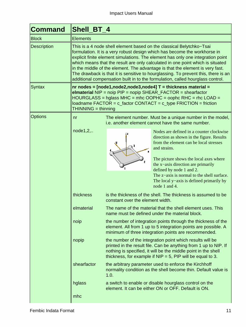
Command Shell_BT_4Block Elements
Description This is a 4 node shell element based on the classical Belytchko−Tsaiformulation. It is a very robust design which has become the workhorse inexplicit finite element simulations. The element has only one integration pointwhich means that the result are only calculated in one point which is situatedin the middle of the element. The advantage is that the element is very fast.The drawback is that it is sensitive to hourglassing. To prevent this, there is anadditional compensation built in to the formulation, called hourglass control.
Syntax nr nodes = [node1,node2,node3,node4] T = thickness material =elmaterial NIP = noip PIP = nopip SHEAR_FACTOR = shearfactorHOURGLASS = hglass MHC = mhc OOPHC = oophc RHC = rhc LOAD =loadname FACTOR = c_factor CONTACT = c_type FRICTION = frictionTHINNING = thinning
Options nr The element number. Must be a unique number in the model,i.e. another element cannot have the same number.
node1,2,.. Nodes are defined in a counter clockwisedirection as shown in the figure. Resultsfrom the element can be local stressesand strains.
The picture shows the local axes wherethe x−axis direction are primarilydefined by node 1 and 2.The z−axis is normal to the shell surface.The local y−axis is defined primarily bynode 1 and 4.
thickness is the thickness of the shell. The thickness is assumed to beconstant over the element width.
elmaterial The name of the material that the shell element uses. Thisname must be defined under the material block.
noip the number of integration points through the thickness of theelement. All from 1 up to 5 integration points are possible. Aminimum of three integration points are recommended.
nopip the number of the integration point which results will beprinted in the result file. Can be anything from 1 up to NIP. Ifnothing is specified, it will be the middle point in the shellthickness, for example if NIP = 5, PIP will be equal to 3.
shearfactor the arbitrary parameter used to enforce the Kirchhoffnormality condition as the shell become thin. Default value is1.0.
hglass a switch to enable or disable hourglass control on theelement. It can be either ON or OFF. Default is ON.
mhc
Impact Users Manual
Fembic Indata Format 11

the Membrane Hourglass Control factor. This factor ismultiplied with the calculated hourglass forces acting in theshell membrane plane. Default is 0.1.
oophc the Out Of Plane Hourglass Control factor. This factor ismultiplied with the calculated hourglass forces acting out ofthe membrane plane, causing ex. twist of the element.Default is 0.1.
rhc the Rotational Hourglass Control factor. This factor ismultiplied with the calculated hourglass moments. Default is0.1.
loadname Name of a load defined under the load block. Pressure ontothe shell element is defined this way.
c_factor The contact factor. This is the reaction force at fullpenetration of contact node.
c_type Contact type. Can be OFF to disable contact. Default contacttype is BASIC which means that two Contact_Triangleelements will represent the surface. This works fine for smalldeformations of the element. ADVANCED will use fourContact_Triangle elements and be able to handle selfcontact within the element itself, but at a cost of calculationtime. EDGE enables edge contact sensitivity along the edgesof the element together with the standard surface contactsensitivity. ADVANCED_EDGE does the latter but togetherwith the advanced contact surface model which uses fourContact_Triangle elements.
friction The friction coefficient to be used. Usually between 0.2 and0.8 depending on material and condition. Only useful ifcontact is enabled. If not set, friction is disabled.
thinning Determines if the shell should reduce thickness at largestrains. Useful in pressing simulations. Default is ON. It canbe disabled by setting equal to OFF.
Example 1 nodes = [113,118,110,106] nip = 5 t = 1.0 material = steel load = pres
See also Elements, Materials, Nodes, Shell_C0_3
Impact Users Manual
Fembic Indata Format 12

Command Shell_C0_3Block Elements
Description This is a 3 node shell element based on the classical C0 formulation byBelytchko et. al. It complement the BT_4 shell and is common in explicit finiteelement simulations. The element has only one integration point which meansthat the result are only calculated in one point which is situated in the middleof the element. The advantage is that the element is very fast. Unlike the BT_4element, this element does not need hourglass control. Triangulars arehowever by it's nature stiffer than the BT_4 element which means it should beused with care.
Syntax nr [node1,node2,node3] T = thickness material = elmaterial NIP = noip PIP= nopip LOAD = loadname FACTOR = c_factor CONTACT = c_typeFRICTION = friction THINNING = thinning
Options nr The element number. Must be a unique number in the model,i.e. another element cannot have the same number.
node1,2,.. Nodes are defined in a counter clockwisedirection as shown in the figure. Resultsfrom the element can be local stressesand strains.
The picture shows the local axes wherethe x−axis direction are primarilydefined by node 1 and 2.The z−axis is normal to the shell surface.The local y−axis is defined to beoctagonal to the x−axis and z−axis.
thickness is the thickness of the shell. The thickness is assumed to beconstant over the element width.
elmaterial The name of the material that the shell element uses. Thisname must be defined under the material block.
noip the number of integration points through the thickness of theelement. All from 1 up to 5 integration points are possible. Aminimum of three integration points are recommended.
nopip the number of the integration point which results will beprinted in the result file. Can be anyting from 1 up to NIP. Ifnothing is specified, it will be the middle point in the shellthickness, for example if NIP = 5, PIP will be equal to 3.
loadname Name of a load defined under the load block. Pressure ontothe shell element is defined this way.
c_factor The contact factor. This is the reaction force at fullpenetration of contact node.
c_type Parameter to set contact sensitivity type. Can be set to OFFto disable contact. If unspecified, contact is enabled forsurface only. If set to EDGE, the surface contact will be
Impact Users Manual
Fembic Indata Format 13

complemented with edge contact sensitivity.
friction The friction coefficient to be used. Usually between 0.2 and0.8 depending on material and condition. Only useful ifcontact is enabled. If not set, friction is disabled.
thinning Determines if the shell should reduce thickness at largestrains. Useful in pressing simulations. Default is ON. It canbe disabled by setting equal to OFF.
Example 1 nodes = [113,118,110] nip = 5 t = 1.0 material = steel load = pres
See also Elements, Materials, Nodes, Shell_BT_4
Impact Users Manual
Fembic Indata Format 14

Command Solid_Iso_6Block Elements
Description This is a simple isoparametric solid element with eight integration points asshowed in the figure. The element is available with either one integration pointwhich is then situated in the middle of the element, or eight integration points.The benefit of having eight points are the the element will be more stablesince hourglass modes cannot occur. At the time of writing, there is nohourglass control algorithm implemented which enables a stable use of oneintegration point which means that this configuration is currently notrecommended. The results from the element are stresses and strains in globaldirections.
Syntax nr [node1,node2,node3,node4, node5,node6,node7,node8] material=elmaterial NIP=noip
Options nr The element number. Must be a unique number in the model,i.e. another element cannot have the same number.
node1,2,.. Nodes are defined as shown in thefigure where the local axes areshown as well. Results from theelement can be local stresses andstrains.
Other types of solid elements canbe created by collapsing theelement edges. This is achieved byassigning the same node number tothe original nodes on the cubeelement. For example, the wedgewould be achieved by assigningnode nr 1 on position 1 and 2 forthe solid element.
In general, the collapse of elementsare not as good as rewriting themfrom scratch. They are howeverpossible to use, but will not giveoptimal results, so be aware of thiswhen using them.
Impact Users Manual
Fembic Indata Format 15

noip the number of integration points in the element; can either be1 or 8. This will also change the result files since results arecalculated in each integration point and the data from eachpoint will then be printed.
elmaterial The name of the material that the rod element uses. Thisname must be defined under the material block.
Example 1 nodes = [23,24,34,42,65,76,89,33] material = steel nip = 82 nodes = [23,23,34,42,65,65,89,33] material = steel nip = 8
See also Elements, Materials, Nodes
Command NodesBlock Nodes
Description The node block starts with the keyword nodes on a single line. The followinglines should then specify the nodes with one node per line. Impact is designedfor three dimensional space problems which means that for each node, allthree space coordinates must be defined at all times. If a two dimensionalproblem is to be solved, each node must be constrained from movement in thethird dimension.
Syntax Nodes
Options −
Example Nodes
See also Node
Impact Users Manual
Fembic Indata Format 16
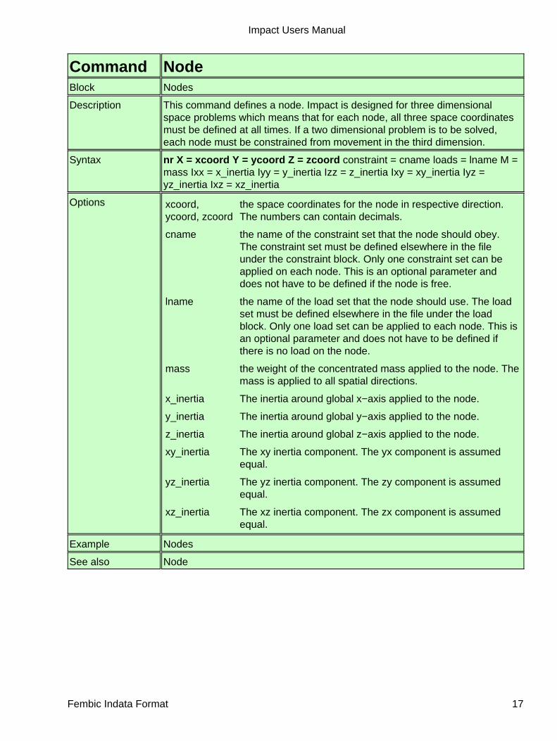
Command NodeBlock Nodes
Description This command defines a node. Impact is designed for three dimensionalspace problems which means that for each node, all three space coordinatesmust be defined at all times. If a two dimensional problem is to be solved,each node must be constrained from movement in the third dimension.
Syntax nr X = xcoord Y = ycoord Z = zcoord constraint = cname loads = lname M =mass Ixx = x_inertia Iyy = y_inertia Izz = z_inertia Ixy = xy_inertia Iyz =yz_inertia Ixz = xz_inertia
Options xcoord,ycoord, zcoord
the space coordinates for the node in respective direction.The numbers can contain decimals.
cname the name of the constraint set that the node should obey.The constraint set must be defined elsewhere in the fileunder the constraint block. Only one constraint set can beapplied on each node. This is an optional parameter anddoes not have to be defined if the node is free.
lname the name of the load set that the node should use. The loadset must be defined elsewhere in the file under the loadblock. Only one load set can be applied to each node. This isan optional parameter and does not have to be defined ifthere is no load on the node.
mass the weight of the concentrated mass applied to the node. Themass is applied to all spatial directions.
x_inertia The inertia around global x−axis applied to the node.
y_inertia The inertia around global y−axis applied to the node.
z_inertia The inertia around global z−axis applied to the node.
xy_inertia The xy inertia component. The yx component is assumedequal.
yz_inertia The yz inertia component. The zy component is assumedequal.
xz_inertia The xz inertia component. The zx component is assumedequal.
Example Nodes
See also Node
Impact Users Manual
Fembic Indata Format 17

Command ConstraintsBlock Constraints
Description Under this block heading, the constraint sets are defined. Each set must bedefined on a single line.
Syntax Constraints of type ctype
Options ctype Any type of constraint: Boundary_Condition, Rigid_Body
Example Constraints of type Boundary_Condition
See also Constraint, Node, Load
Command Boundary_ConditionBlock Constraints
Description Defines a boundary condition constraint. A constraint controls movement forthe nodes in different directions by setting the acceleration and velocity for thenode. Any given combination can be set. There is no need to define all thevariables. If none is set, the default value is that the node will be uncontrolledin that direction.
Syntax name ax = value ay = value az = value vx = value vy = value vz = value arx =value ary = value arz = value vrx = value vry = value vrz = value axis =[node1,node2,node3] update = upd
Options name Name of the constraint. Must be unique.
value Value of the constraint. Can be either a simple number(constant) or alternatively a variable over time definedas [t1,y1,t2,y2,...,tn,yn] where y1 is the value at time t1and so on. At this stage, y1 can also be off whichmeans that the constraint will not be effective from thistime forward until a new value is set.
node1,node2,node3 These nodes set up the local coordinate system for theboundary condition. If these are specified, the valuesspecified in the constraint will be assumed to be relatingto this local coordinate system. The local x−axis of thesystem runs from node1 to node2. Local z−axis is thennormal to the plane defined by this x−axis and a vectorfrom node1 to node3. Finally, the y−axis is normal to thex− and z−axis.
upd The update option is connected to the axis option. If thelocal coordinate system is defined and update is set toON, the nodes defining the coordinate system will becontinuosly scanned and the system updated. Thismeans the system can rotate over time.
Example exampleconstraint ax = [0,0,1,1.5,5,off,6,3,100,3] ay = 3.0 az = 0.0
See also Node, Load
Impact Users Manual
Fembic Indata Format 18

Command Rigid_BodyBlock Constraints
Description Defines a rigid body constraint. The nodes referring to this constraint are allconsidered part of a single rigid body. They are all connected to the masternode. If specified, the master node can automatically be placed in the centreof gravity for the body. The movement of the body will be controlled from themaster node, on which an ordinary boundary condition or load can be placed.The master node will automatically be given the mass and inertia for the rigidbody, based on the slave nodes mass, inertia and position.
Syntax name master_node = nnum update_position = updt
Options name Name of the constraint. Must be unique.
nnum Node number of the master node. The node will be movedautomatically to the centre of gravity of the rigid body beforethe solution starts.
updt If this is set to ON, the master node will automatically bemoved to the centre of mass for the rigid body before thesolution starts.
Example rb1 master_node = 25
See also Boundary_Condition, Node
Command LoadsBlock Loads
Description Under this block heading, the load sets are defined. Each set must be definedon a single line.
Syntax Loads
Options −
Example Loads
See also Load, Node, Constraint
Impact Users Manual
Fembic Indata Format 19

Command LoadBlock Loads
Description The loads block is initiated by the heading above on a single line. The loadsthemselves follows, defined one per line. A load set is applied on nodes orsome elements. It consists of concentrated forces in any direction defined bytheir x,y and z components. Accelerations, such as gravity can also be definedhere. Pressure can also be defined.
Syntax name fx = value fy = value fz = value mx = value my = value mz = value ax =acc ay = acc az = acc arx = acc ary = acc arz = acc p = pressure
Options name Name of the load. Must be unique.
value Value of the load. Can be either a simple number (constant)or alternatively a variable over time defined as[t1,y1,t2,y2,...,tn,yn] where y1 is the value at time t1 and soon. At this stage, y1 can also be off which means that theload will not be effective from this time forward until a newvalue is set.
acc Value of the acceleration. Accelerations are added to theload on a node which makes this the way to simulate gravity.Acceleration can be either a simple number (constant) oralternatively a variable over time defined as[t1,y1,t2,y2,...,tn,yn] where y1 is the acceleration at time t1and so on. At this stage, y1 can also be off which means thatthe acceleration will not be effective from this time forwarduntil a new value is set.
pressure Value of the pressure. Can be either a simple number(constant) or alternatively a variable over time defined as[t1,y1,t2,y2,...,tn,yn] where y1 is the pressure at time t1 andso on. At this stage, y1 can also be off which means that thepressure will not be effective from this time forward until anew value is set.
Example exampleload ax = [0,0,1,1.5,5,off,6,3,100,3] p = 3.0
See also Node, Load
Impact Users Manual
Fembic Indata Format 20

Command MaterialsBlock Materials
Description A specific material is defined by setting the parameters of a specific materiallaw. There are several material laws available, depending on material choice.There are laws that are suitable for metals and other more suitable for foams,which may behave differently. The material law is then assigned to one orseveral elements in the element definition.
Syntax Materials of type mtype
Options mtype The name of a specific material law. After each blockheading, the specific materials are listed with the parametersdefined. One material per line.
Example Materials of Type Elastic
See also Elastic, Elastoplastic
Command ElasticBlock Materials
Description This is a simple elastic material law.
Syntax name E = yvalue RHO = dvalue NU = nuvalue FAILURE_STRAIN = fstrainFAILURE_STESS = fstress
Options name Name of the material. Must be unique.
yvalue Young's modulus for the material.
dvalue The density of the material.
nuvalue Poisson's constant of the material.
fstrain The strain at which the material fractures. If an elementreaches this strain, it will be removed from the simulation.
nuvalue The stress at which the material fractures. If an elementreaches this stress, it will be removed from the simulation.
Example steel E = 210 D = 0.0000078 NU = 0.3
See also Elements, Materials, Elastoplastic
Impact Users Manual
Fembic Indata Format 21

Command ElastoplasticBlock Materials
Description This is an isoparametric elasto−plastic material law. The elastic Young'smodulus defines the stress−strain relation up to the yield stress. Above yieldstress, there are several options. The plastic behaviour can be described bythe plastic modulus (EP) which defines a linear relation between the stressand effective plastic strain. This relation can also be a curve, defined by arange of stress/strain coordinates. The EP in this case has no function andcan be omitted. Finally, the relation can also be dependent on the strain rate inwhich several stress/strain curves are defined together with a parametersetting the velocity for which each curve is representative. The stress for acertain effective strain value is detemined as a linear interpolation from thesecurves.
Syntax name E = yvalue RHO = dvalue NU = nuvalue YIELD_STRESS = svalueEP = fvalue Y1,Y2.. Y9 = svalue V1,V2..V9 = vvalues FAILURE_STRAIN =fstrain FAILURE_STESS = fstress
Options name Name of the material. Must be unique.
yvalue Young's modulus for the material.
dvalue The density of the material.
nuvalue Poisson's constant of the material.
svalue The yield stress of the material. If this is a single number, theEP variable must be set in order to define a linear plasticrelation. The second option is to define the yield stress as arange of strain/stress coordinate pairs. Example is[eps0,stress0,eps1,stress2,....,epsn,stressn]. Remember thatthe strain is effective plastic strain which is equal to zero atinitial yield. When the Y1,2... parameters are used, thisstress/strain curve is defined for a certain strain rate, definedin the corresponding vvalue
fvalue is the plastic modulus or tangent modulus in the plasticregion. If a curve is defined for the yield stress, thisparameter is not needed.
vvalue is the strain rate for which the Yx curve is defined. The V1value defines the strain rate for Y1 and so on. Thestress/strain curve for a zero velocity is defined in theordinary YIELD_STRESS parameter.
fstrain The strain at which the material fractures. If an elementreaches this strain, it will be removed from the simulation.
nuvalue The stress at which the material fractures. If an elementreaches this stress, it will be removed from the simulation.
Example epsteel E = 210 RHO = 0.0000078 NU = 0.3 YIELD_STRESS = 0.180 EP =0.1steel2 E = 210 RHO = 0.0000078 NU = 0.3 YIELD_STRESS =[0,0.180,0.3,0.220,2.0,0.250]
Impact Users Manual
Fembic Indata Format 22

v_steel E = 210 RHO = 0.0000078 NU = 0.3 YIELD_STRESS =[0,0.180,0.3,0.220] V1 = 0.2 Y1 = [0,0.200,0.3,0.240]
See also Elements, Materials, Elastic
Impact Users Manual
Fembic Indata Format 23
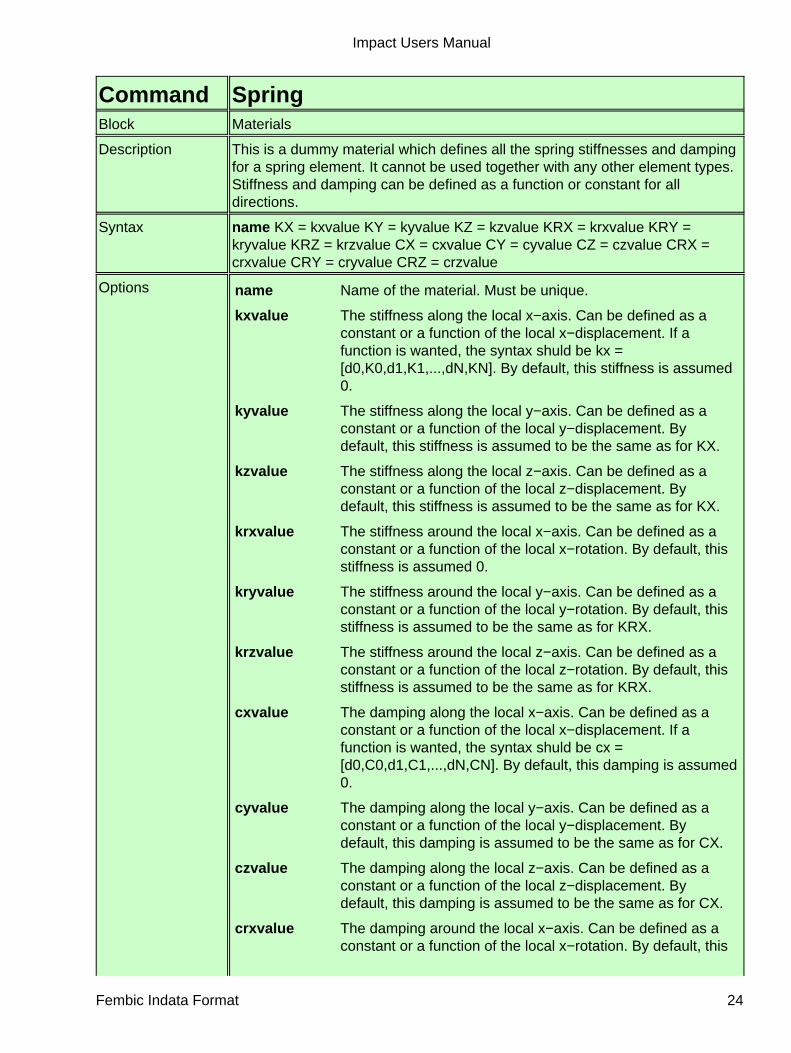
Command SpringBlock Materials
Description This is a dummy material which defines all the spring stiffnesses and dampingfor a spring element. It cannot be used together with any other element types.Stiffness and damping can be defined as a function or constant for alldirections.
Syntax name KX = kxvalue KY = kyvalue KZ = kzvalue KRX = krxvalue KRY =kryvalue KRZ = krzvalue CX = cxvalue CY = cyvalue CZ = czvalue CRX =crxvalue CRY = cryvalue CRZ = crzvalue
Options name Name of the material. Must be unique.
kxvalue The stiffness along the local x−axis. Can be defined as aconstant or a function of the local x−displacement. If afunction is wanted, the syntax shuld be kx =[d0,K0,d1,K1,...,dN,KN]. By default, this stiffness is assumed0.
kyvalue The stiffness along the local y−axis. Can be defined as aconstant or a function of the local y−displacement. Bydefault, this stiffness is assumed to be the same as for KX.
kzvalue The stiffness along the local z−axis. Can be defined as aconstant or a function of the local z−displacement. Bydefault, this stiffness is assumed to be the same as for KX.
krxvalue The stiffness around the local x−axis. Can be defined as aconstant or a function of the local x−rotation. By default, thisstiffness is assumed 0.
kryvalue The stiffness around the local y−axis. Can be defined as aconstant or a function of the local y−rotation. By default, thisstiffness is assumed to be the same as for KRX.
krzvalue The stiffness around the local z−axis. Can be defined as aconstant or a function of the local z−rotation. By default, thisstiffness is assumed to be the same as for KRX.
cxvalue The damping along the local x−axis. Can be defined as aconstant or a function of the local x−displacement. If afunction is wanted, the syntax shuld be cx =[d0,C0,d1,C1,...,dN,CN]. By default, this damping is assumed0.
cyvalue The damping along the local y−axis. Can be defined as aconstant or a function of the local y−displacement. Bydefault, this damping is assumed to be the same as for CX.
czvalue The damping along the local z−axis. Can be defined as aconstant or a function of the local z−displacement. Bydefault, this damping is assumed to be the same as for CX.
crxvalue The damping around the local x−axis. Can be defined as aconstant or a function of the local x−rotation. By default, this
Impact Users Manual
Fembic Indata Format 24

damping is assumed 0.
cryvalue The damping around the local y−axis. Can be defined as aconstant or a function of the local y−rotation. By default, thisdamping is assumed to be the same as for CRX.
crzvalue The stiffness around the local z−axis. Can be defined as aconstant or a function of the local z−rotation. By default, thisdamping is assumed to be the same as for CRX.
Example attrib KX = 10 CX = [0,0,1,20,2,off,3,30,45,0]
See also Elements, Materials, Elastoplastic
Command TrackersBlock Trackers
Description The trackers are used to track result data from a solution. There are severaldifferent trackers, each specially tailored for different results.
Syntax Trackers of Type ttype
Options ttype Any type of tracker: Nodeforce, Sectionforce, etc
Example Trackers of Type Nodeforce
See also Nodeforce, Sectionforce
Impact Users Manual
Fembic Indata Format 25

Command NodeforceBlock Trackers
Description This tracker reads the forces from one or several nodes and plots the resultinto a file. The file is currently readable by the GID pre/postprocessor but thetracker can also print in a different fileformat. This is controlled by theTrackwriter command. Target is a value set by the user. If this value isreached during simulation, a file will be written (with extension .target). This isuseful when debugging new versions of Impact.
Syntax nr nodes = [tnode,tnode,...,tnode] DIRECTION = dir FILENAME = fnameTARGET = [ttime,timetol,tvalue,valuetol]
Options nr The tracker number. Must be a unique number in the model,i.e. another nodetracker cannot have the same number.
tnode The number of the node to track forces from.
dir The direction of the force to track. Can be either 'X', 'Y' or 'Z'.It is also possible to select components thereof by adding a −or +, i.e. 'X+' will plot the component acting in the positive Xdirection. If only X is used, the sum of the positive andnegative component will be plotted.
filename The name of the file of which the nodetracker should write.Must be a unique name for each nodetracker.
ttime The time where the target is to be checked.
ttol The tolerance for the target time
tvalue The target value.
valuetol The tolerance for the target value
Example 1 nodes = [23] direction = x+ filename = nodeforce.trk
See also Trackwriter, Sectionforce, Trackers
Impact Users Manual
Fembic Indata Format 26

Command NodemomentBlock Trackers
Description This tracker reads the moments from one or several nodes and plots the resultinto a file. The file is currently readable by the GID pre/postprocessor but thetracker can also print in a different fileformat. This is controlled by theTrackwriter command. Target is a value set by the user. If this value isreached during simulation, a file will be written (with extension .target). This isuseful when debugging new versions of Impact.
Syntax nr nodes = [tnode,tnode,...,tnode] DIRECTION = dir FILENAME = fnameTARGET = [ttime,timetol,tvalue,valuetol]
Options nr The tracker number. Must be a unique number in the model,i.e. another nodetracker cannot have the same number.
tnode The number of the node to track moments from.
dir The direction of the moment to track. Can be either 'X', 'Y' or'Z'. It is also possible to select components thereof by addinga − or +, i.e. 'X+' will plot the component acting in the positiveX rotation direction. If only X is used, the sum of the positiveand negative component will be plotted.
filename The name of the file of which the nodetracker should write.Must be a unique name for each nodetracker.
ttime The time where the target is to be checked.
ttol The tolerance for the target time
tvalue The target value.
valuetol The tolerance for the target value
Example 1 nodes = [23] direction = x+ filename = nodemoment.trk
See also Trackwriter, Nodeforce, Sectionforce, Trackers
Impact Users Manual
Fembic Indata Format 27

Command NodeDisplacementBlock Trackers
Description This tracker reads the displacement of a single node and plots the result into afile. The file is currently readable by the GID pre/postprocessor but the trackercan also print in a different fileformat. This is controlled by the Trackwritercommand. Target is a value set by the user. If this value is reached duringsimulation, a file will be written (with extension .target). This is useful whendebugging new versions of Impact.
Syntax nr node = [tnode] DIRECTION = dir FILENAME = fname TARGET =[ttime,timetol,tvalue,valuetol]
Options nr The tracker number. Must be a unique number in the model,i.e. another nodetracker cannot have the same number.
tnode The number of the node to track displacement from.
dir The direction of the displacement to track. Can be either 'X','Y' or 'Z'
filename The name of the file of which the nodetracker should write.Must be a unique name for each nodetracker.
ttime The time where the target is to be checked.
ttol The tolerance for the target time
tvalue The target value.
valuetol The tolerance for the target value
Example 1 node = [23] direction = z filename = nodedisp.trk
See also Trackwriter, Sectionforce, Trackers
Impact Users Manual
Fembic Indata Format 28

Command NodeAccelerationBlock Trackers
Description This tracker reads the acceleration of a single node and plots the result into afile. The file is currently readable by the GID pre/postprocessor but the trackercan also print in a different fileformat. This is controlled by the Trackwritercommand. Target is a value set by the user. If this value is reached duringsimulation, a file will be written (with extension .target). This is useful whendebugging new versions of Impact.
Syntax nr node = [tnode] DIRECTION = dir FILENAME = fname TARGET =[ttime,timetol,tvalue,valuetol]
Options nr The tracker number. Must be a unique number in the model,i.e. another nodetracker cannot have the same number.
tnode The number of the node to track acceleration from.
dir The direction of the acceleration to track. Can be either 'X','Y' or 'Z'
filename The name of the file of which the nodetracker should write.Must be a unique name for each nodetracker.
ttime The time where the target is to be checked.
ttol The tolerance for the target time
tvalue The target value.
valuetol The tolerance for the target value
Example 1 node = [23] direction = z filename = nodeacc.trk
See also Trackwriter, Sectionforce, Trackers
Impact Users Manual
Fembic Indata Format 29

Command SectionforceBlock Trackers
Description This tracker collects the nodal forces from a range of nodes. The first three ofthe nodes is the basis of a plane of which a normal axis is calculated. Theforce from each node is calculated in this direction, summarised and thenplotted. A minimum of three nodes must be specified.This tracker is suitable for measuring the load through a cross section of amember or a beam.
Syntax nr nodes = [node1,node2,node3,nodeN] direction = dir filename = fname
Options nr The tracker number. Must be a unique number in the model,i.e. another sectionforcetracker cannot have the samenumber.
node1,2,.. The number of the first node etc. The first three nodes aremandatory. The rest are optional.
dir The direction of the forces to be collected. Can only be equalto "negative". When set, all the forces acting in the oppositedirection to the section normal will be summed. If thisparameter is not specified at all, the forces acting in thesame direction as the section normal will be summed(default).
filename The filename of the result file of which the tracker shouldprint the results. Must be unique for each tracker.
Example 1 nodes = [23,24,12,34,15] filename = sectionforce_1.trk
See also Nodeforce, Trackwriter, Trackers
Impact Users Manual
Fembic Indata Format 30

Command EnergyBlock Trackers
Description This tracker reads the energy from the model and plots it. There are severaldifferent energy types that can be plotted, but only one per tracker
Syntax nr TYPE = ttype FILENAME = fname TARGET =[ttime,timetol,tvalue,valuetol]
Options nr The tracker number. Must be a unique number in the model,i.e. another nodetracker cannot have the same number.
ttype The type of energy to plot. Can be one of
contact − for contact energy.• external − for external applied energy.• internal − for internal absorbed energy.• hourglass − for hourglass energy used to stabilizesome elements.
•
filename The name of the file of which the energytracker should write.Must be a unique name for each energytracker.
ttime The time where the target is to be checked.
ttol The tolerance for the target time
tvalue The target value.
valuetol The tolerance for the target value
Example 1 type = external filename = energy_external.trk
See also Trackwriter, Sectionforce, Trackers
Impact Users Manual
Fembic Indata Format 31

Command NodeDistanceBlock Trackers
Description This tracker calculates the distance between two nodes and plots it as afunction of time into a selected file. The distance is the shortest spacedistance.
Syntax nr node = [node1,node2] FILENAME = fname TARGET =[ttime,timetol,tvalue,valuetol]
Options nr The tracker number. Must be a unique number in the model,i.e. another NodeDistance tracker cannot have the samenumber.
node1,node2 The number of the nodes to track distance between.
filename The name of the file of which the tracker should write. Mustbe a unique name for each tracker.
ttime The time where the target is to be checked.
ttol The tolerance for the target time
tvalue The target value.
valuetol The tolerance for the target value
Example 1 node = [23,15] filename = nodedist.trk
See also Trackwriter, Sectionforce, Trackers
Command RodForceBlock Trackers
Description This tracker reads the local force from a given Rod_2 element. The force isthen plotted into a file as a function of time. Note that the force is always localand not plotted in any global direction.
Syntax nr element = [telem] FILENAME = fname TARGET =[ttime,timetol,tvalue,valuetol]
Options nr The tracker number. Must be a unique number in the model,i.e. another RodForce tracker cannot have the same number.
telem The number of the Rod_2 element to track force from.
filename The name of the file of which the tracker should write. Mustbe a unique name for each tracker.
ttime The time where the target is to be checked.
ttol The tolerance for the target time
tvalue The target value.
valuetol The tolerance for the target value
Example 1 element = [23] filename = rodforce.trk
See also Trackwriter, Sectionforce, Trackers
Impact Users Manual
Fembic Indata Format 32

Command BeamSpringBlock Trackers
Description This tracker reads the local force from a given Beam_Spring_2 element. Theforce or moment is then plotted into a file as a function of time. Note that theforce or moment is always local and not plotted in any global direction.
Syntax nr element = [telem] FILENAME = fname COMPONENT = comp TARGET =[ttime,timetol,tvalue,valuetol]
Options nr The tracker number. Must be a unique number in the model,i.e. another BeamSpring tracker cannot have the samenumber.
telem The number of the Beam_Spring_2 element to track force ormoment from.
filename The name of the file of which the tracker should write. Mustbe a unique name for each tracker.
comp Sets which component to track. Can be one of: FX, FY, FZ,MX, MY, MZ. If nothing is set here, the default is to track theFX component.
ttime The time where the target is to be checked.
ttol The tolerance for the target time
tvalue The target value.
valuetol The tolerance for the target value
Example 1 element = [23] filename = beamspring_mz.trk component = mz
See also Trackwriter, Sectionforce, Trackers, Beam_Spring_2
Command ControlsBlock Controls
Description The control block is initiated with the word control on a single line. There canonly be one control block in any give indata file. All commands designed tocontrol the solution process is defined here. One command with it's associatedparameters is defined on each line.
Syntax Controls
Options
Example Controls
See also Run, Print
Impact Users Manual
Fembic Indata Format 33

Command RunBlock Controls
Description This command controls the solution process. The starting time and the endtime are mandatory while control of the step size is optional. if this is left blank,impact will choose the most optimal step size for each step during the solutionprocess.
Syntax Run from svalue to evalue step stpvalue
Options svalue Start time for the solution
evalue End time for the solution.
stpvalue Stepsize for the solution. Specifying this value disablesautostep.
Example Run from 0.0 to 1.2 step 0.0001
See also Controls, Print
Command PrintBlock Controls
Description This command controls the print process during the solution. The commandcan also be repeated with the tracker word if the printing interval is to be setspecifically for the trackers. Impact will print the results with the intervalspecified. Depending on how the element perform it's internal calculations, theoutput may be local or global stresses and strains. Displacements of nodesare also printed so that mesh deformation can be followed. If no specificinterval will be set for the trackers, they will print at the same time as thegeneral printing occurs.
Syntax print tracker every value step
Options value Step time for printing.
Example Print every 0.01 step
See also Controls, Run
Impact Users Manual
Fembic Indata Format 34
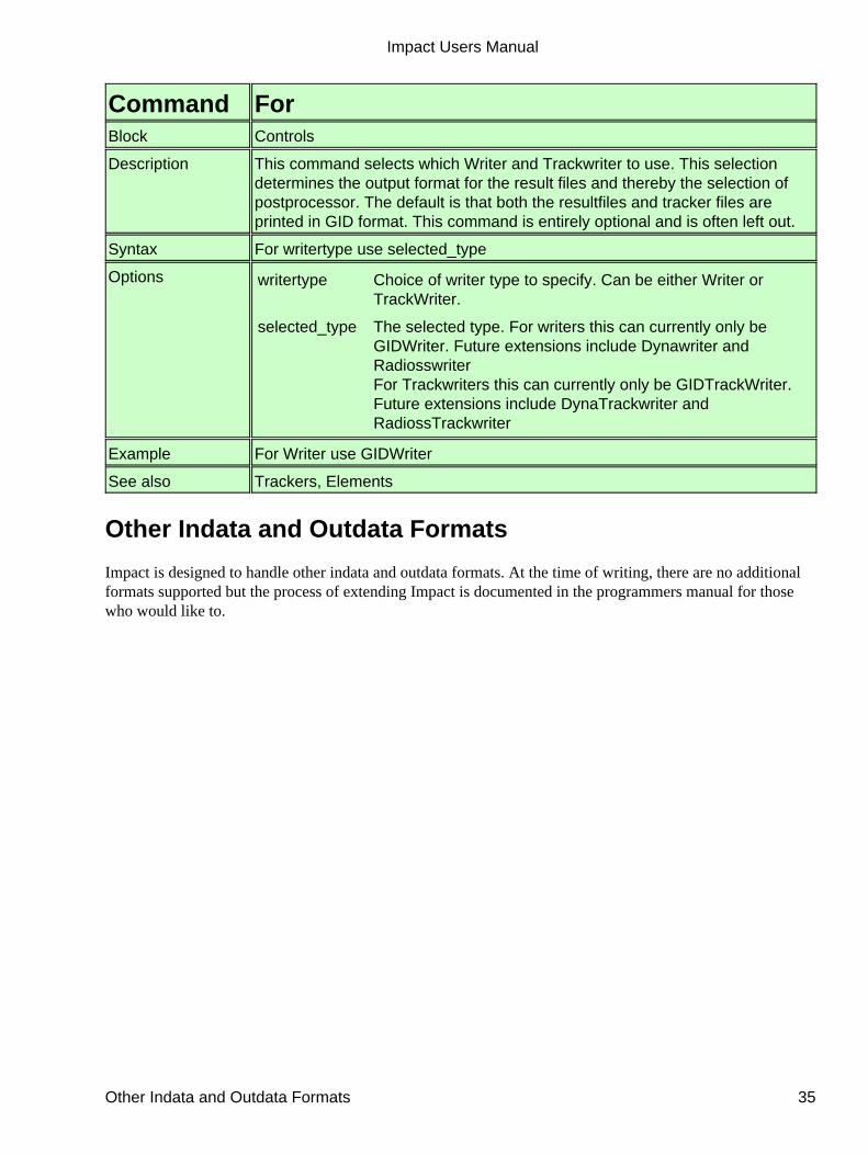
Command ForBlock Controls
Description This command selects which Writer and Trackwriter to use. This selectiondetermines the output format for the result files and thereby the selection ofpostprocessor. The default is that both the resultfiles and tracker files areprinted in GID format. This command is entirely optional and is often left out.
Syntax For writertype use selected_type
Options writertype Choice of writer type to specify. Can be either Writer orTrackWriter.
selected_type The selected type. For writers this can currently only beGIDWriter. Future extensions include Dynawriter andRadiosswriterFor Trackwriters this can currently only be GIDTrackWriter.Future extensions include DynaTrackwriter andRadiossTrackwriter
Example For Writer use GIDWriter
See also Trackers, Elements
Other Indata and Outdata Formats
Impact is designed to handle other indata and outdata formats. At the time of writing, there are no additionalformats supported but the process of extending Impact is documented in the programmers manual for thosewho would like to.
Impact Users Manual
Other Indata and Outdata Formats 35