impedance bridge impedance bridge.pdf · 1.4 series and parallel parameters. an impedance that is...
TRANSCRIPT
INSTRUCTION MANUAL
TYPE 1608-A
IMPEDANCE BRIDGE
GENERAL RADIO COMPANY
c
-o-0 (X) I
>
OPERATING INSTRUCTIONS
1608-A
IMPEDANCE BRIDGE Form 1608-0100-C
Jan uar , 1967
Copyright 1962 by General Radio Company West Concord, Massachusetts, USA
GENERAL R A D I 0 COMPANY WEST CONCORD, MASSACHUSETTS, USA
TABLE
Section 1. INTRODUCTION
1.1 Purpose. . . . . . 1.2 Description • . . .
OF CONTENTS
1.3 Symbols, Abbreviations, and Definitions 1.4 Series and Parallel Parameters • 1.5 Accuracy of Measurements . . .
Section 2. OPERATING PROCEDURE .
2.1 Installation • . . . . . . . . 2.2 Interpretation of "X" in Read-out 2.3 DC Resistance Measurements .. 2.4 AC Measurements using Internal Generator. 2. 5 AC Measurements with External Generator •
Section 3. SPECIAL MEASUREMENTS . . . . . .
1
1 1 1
. 4
. 4
9
9 9
. 9
. 12 . . 19
• 22
3.1 Application of DC Bias to Unknown . . . . . . . . 22 3.2 Measurements on Shielded Three-'! ermmal Components • . . 26 3.3 Remote Measurements . . . . . . . . . . 26 3.4 Use of Type 1650-Pl Test Jig • . . . . . . . . . • . . 27 3.5 Measurements on Grounded Components • • . • . . . . • . 27 3. 6 Limit Testing . . . . . • . . . . . • . . . . . . . . 27 3. 7 Measuring Resonant Frequency and Resonant Impedance of
Tuned Circuits . . . 27 3.8 Measurement of Rp. . . . . . . • . . • . . . • . . . . .28
Section 4. PRINCIPLES OF OPERATION
4.1 Bridge Circuits •..... 4.2 Bridge Sources and Detectors •. 4.3 Bridge Switching . . . . • . . . 4.4 Centade Operation . . • . . . . 4.5 Phase-Compensation Techniques.
Section 5. SERVICE AND MAINTENANCE
5.1 General. . . . • . 5.2 Calibration Checks. . . . 5.3 Adjustments. . . . • .' . • 5.4 Replacing Indicator Lamps • 5.5 Trouble-Shooting Suggestions •. 5.6 Tables of Test Voltages
. . • 28
. 28
. 28
. 29
. 29
. 30
. . 31
. 31
. 31 • 32
. . . 33 . 33
• . 34
SPECIFICATIONSI
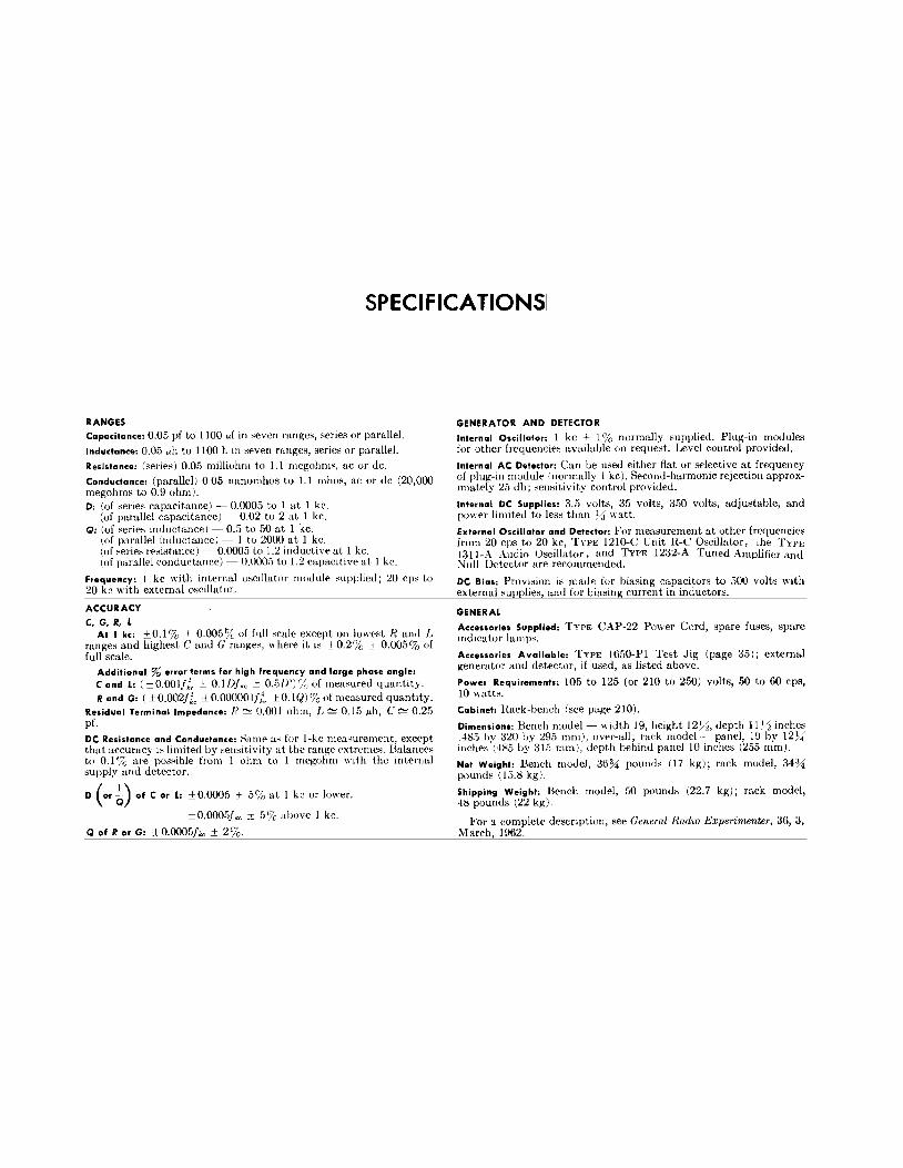
RANGES Capacitance: 0.05 pf to 1100 ,..r in seven ranges, series or parallel.
Inductance: 0.05 l'h to 1100 h in seven ranges, series or parallel. Resistance: (series) 0.05 milliohm to 1.1 megohms, ac or de. Conductance: (parallel) 0.05 nanomhos to 1.1 mhos, ac or de (20,000 megohms to 0.9 ohm). 0: (of series capacitance)- 0.0005 to 1 at 1 kc.
(of parallel capacitance) - 0.02 to 2 at 1 kc. Q: (of series inductance)-· 0.5 to 50 at 1 kc.
(of parallel inductance)- 1 to 2000 at 1 kc. (of series resistance)- 0.0005 to 1.2 inductive at 1 kc. (of parallel conductance)- 0.0005 to 1.2 capacitive at 1 kc.
Frequency: 1 kc with internal oscillator module supplied; 20 cps to 20 kc with external oscillator.
ACCURACY
C, G, R, L At 1 kc: ± 0.1% ± 0.005% of full scale except on lowest R and L
ranges and highest C and Granges, where it is ±0.2% ± 0.005% of full scale.
Additional % error terms for high frequency and large phase angle: C and L: ( ±0.001fi, ± 0.11Jfkc ::':: 0.5/)2)'/n of measured quantity. Rand G: (±0.002Ji, ±O.OOOOOIJZ, ±0.1Q)%ofmeasuredquantity.
Residual Terminal Impedance: H ~ 0.001 ohm, L ~ 0.15 l'h, C ~ 0.25 pf.
DC Resistance and Conductance: Same m; for I-ke measurement, except that accuracy b limited by sensitivity at the ran~~:e extremes. Balances to 0.1% are possible from 1 ohm to 1 megohm with the internal supply and detector.
D (or~) of Cor L: ±0.0005 ± 5% at I kc or lower.
±0.0005fkc ± 5% above 1 kc.
Q of R or G: ±0.0005fk, ± 2%.
GENERATOR AND DETECTOR
Internal Oscillator: 1 kc ± 1% normally supplied. Plug-in modules for other frequencies available on request. Level control provided.
Internal AC Detector: Can be used either flat or selective at frequency of plug-in module (normally 1 kc). Second-harmonic rejection approximately 25 db; sensitivity control provided.
Internal DC Supplies: 3.5 volts, 35 volts, 350 volts, adjustable, and power limited to less than Ya watt.
External Oscillator and Detector: For measurement at othE>r frequencies from 20 cps to 20 kc, TYPE 1210-C Unit l{-C Oscillator, che TYPJo; 1311-A Audio Oscillator, and TYPE 1232-A Tuned Amplifier and ~ull Detector are recommended.
DC Bias: Provision is made for biasing capacitors to 500 volts with external supplies, and for biasing current in inductors.
GENERAL
Accessories Supplied: TYPE CAP-22 Power Cord, spare fuses, spare indicator lamps.
Accessories Available: TYPE 1650-Pl Test Jig (page 35); external generator and detector, if used, as listed above.
Power Requirements: 105 to 125 (or 210 to 250) volts, 50 to 60 cps, 10 watts.
Cabinet: Hack-bench (see page 210).
Dimensions: Bench model-- width 19, height 12~~. depth 11!/:1 inches (485 by 320 by 295 mm), over-all; rack model- panel, 19 by 12~ inches (485 by 315 mm), depth behind panel 10 inches (255 rnm).
Net Weight: Bench model, 36% pounds (17 kg); rack model, 34% pounds (15.8 kg).
Shipping Weight: Bench model, 50 pounds (22. 7 kg); rack model, 48 pounds (22 kg).
For a complete description, see General Radio Experimenter, 36, 3, March 1962.
6
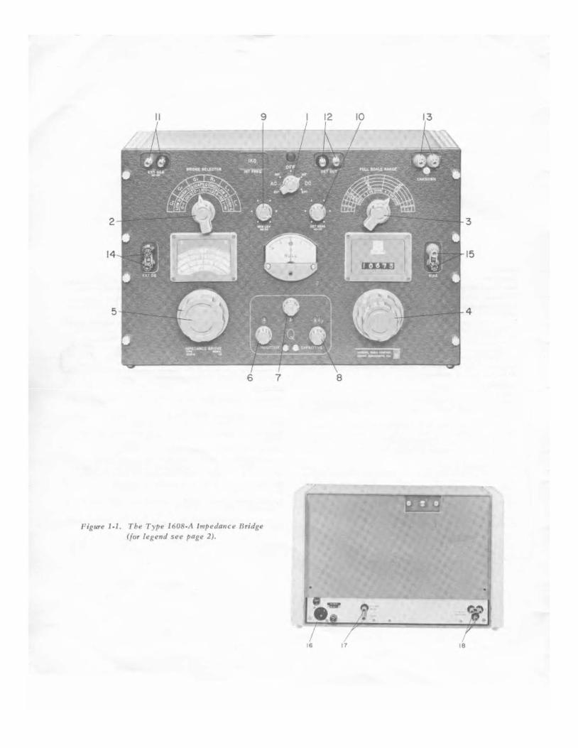
Figll1'«' J.J. The T)pe 1608-A Impedance llridge ({or legend Sl'l' pag" 2).
7
t 6
3
15
4
8
17 18
'IN T R 0 DUCT I 0 N
SECTION 1
INTRODUCTION
1.1 PURPOSE.
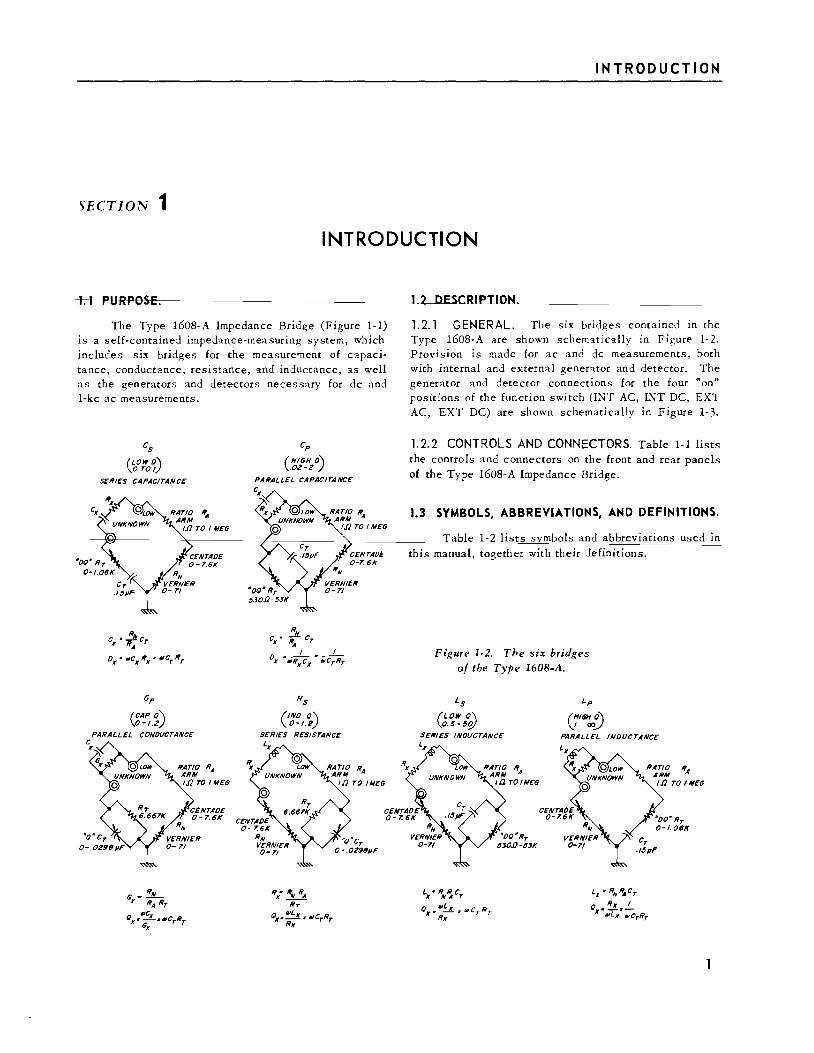
The Type 1608-A Impedance Bridge (Figure 1-1) is a self-contained impedance-measuring system, which includes six bridges for the measure'llent of capacitance, conductance, resistance, and inductance, as well as the generators and detectors necessary for de and 1-kc ac measurements.
cs
(LOW O\ 0 TO!)
SERIES CAPACITANCE
ex ·~Cr A
OX • IIICXRX • IIICTRT
Gp
(CAP()) 0-1.2
CONOIICTANCE
Cp
(HIGH 0\ .02-2 J
PARALLEL CAPACITANCE
Rs
(/NO C\ 0-1.2)
SERIES RESISTANCE
1 2 DESCRIPTION
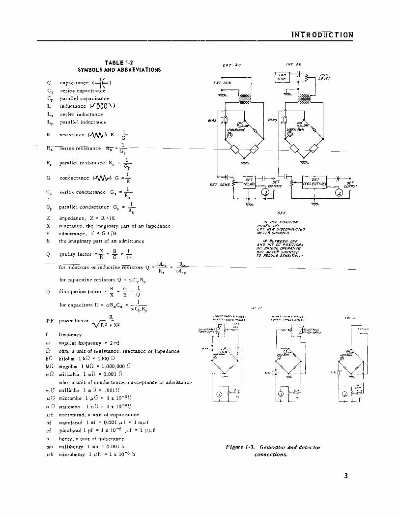
1.2.1 GENERAL. The six bridges contained in the Type 1608-A are shown schematically in Figure 1-2. Provision is made for ac and de measurements, both with internal and external generator and detector. The generator and detector connections for the four "on" positions of the function switch (INT AC, INT DC, EXT AC, EXT DC) are shown schematically in Figure 1-3.
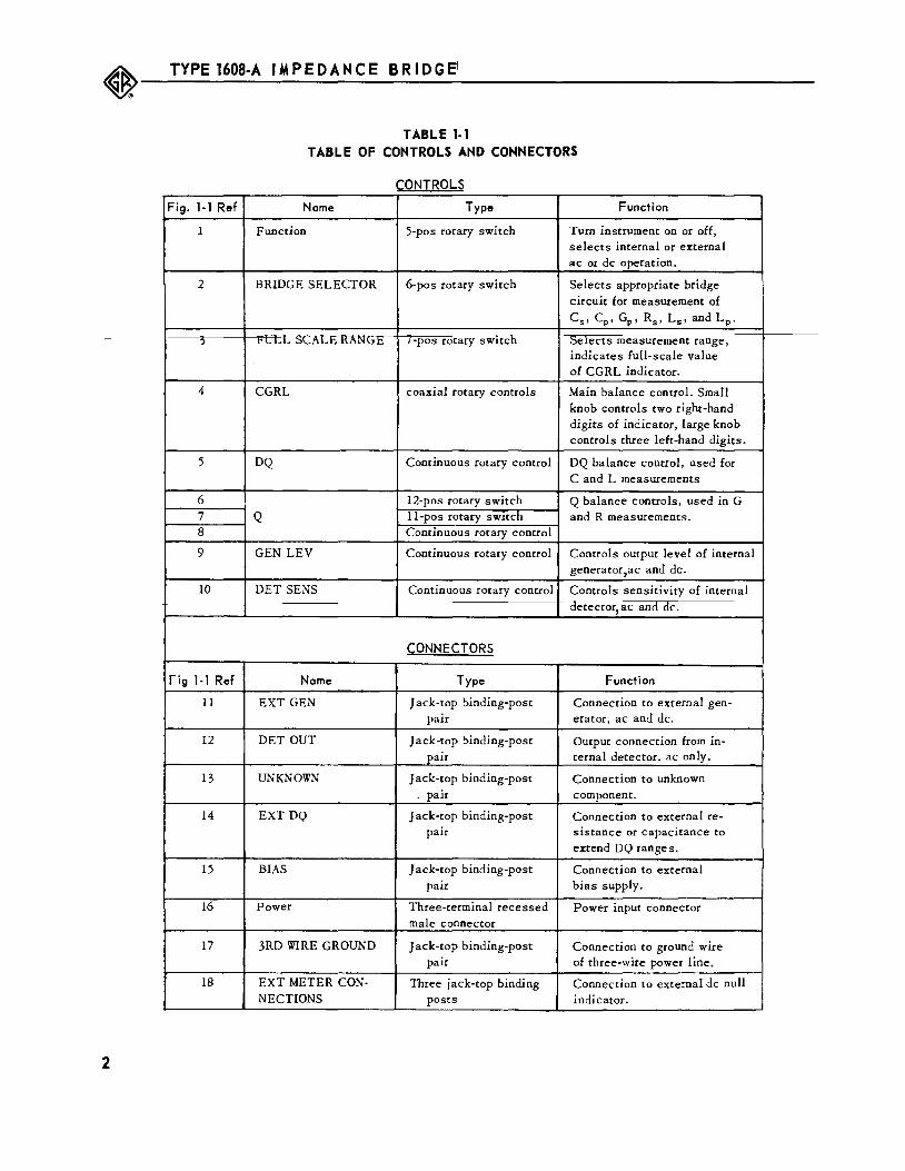
1.2.2 CONTROLS AND CONNECTORS. Table 1-1 lists the contro Is and connectors on the front and rear panels of the Type 1608-A Impedance Bridge.
1.3 SYMBOLS, ABBREVIATIONS, AND DEFINITIONS.
Table 1-2 lists s mbols and abbreviations used in this manual, together with their definitions.
Figure 1-2. The six bridges of the Type 1608-A.
Ls
GLOW C\ 0.$- $g/
SERIES INOIICTANCE
Lx• RN~CT
Ox" IIILx • t~~CrRr Rx
Lp
(HIGH C\ 1- oo..J
PARALLEL INOIICTANCE
Lx • RN~CT
ox.'!.!..:.:_:_ OJLx .,crRr
~---T_Y_PE __ 16_08_-A __ I_M_P_E_D_A_N_C_E __ B_R_ID_G_E_1
__________________________ ___
TABLEl-1 TABLE OF CONTROLS AND CONNECTORS
CONTROLS Fig. 1· 1 Ref Name Type Function
1 Function 5-pos rotary switch Tum instrument on or off, selects internal or external ac or de operation.
2 BRIDGE SELECTOR 6-pos rotary switch Selects appropriate bridge circuit for measurement of
C 8 , CP, GP, R8 , L 5 , and LP.
::> t'ULL :::>1...1\Lt Kl\l'H:rt i·pos rotary switch ::Selects measurement range, indicates full-scale value of CGRL indicator.
4 CGRL coaxial rotary controls Main balance control. Small knob controls two right-hand digits of indicator, large knob controls three left-hand digits.
5 DQ Continuous rotary control DQ balance control, used for C and L measurements
6 12-pos rotary switch Q balance controls, used in G 7 Q ll·pos rotary switch and R measurements. 8 Continuous rotary control
9 GEN LEV Continuous rotary control Controls output level of internal generator,ac and de.
10 DET SENS Continuous rotary control Controls sensitivity of internal detector, ac and de.
CONNECTORS
Fig 1-1 Ref Name Type Function
11 EXT GEN J ack·top binding-post Connection to external gen-pair erator, ac and de.
12 DET OUT J ack·top binding· post Output connection from in-pair ternal detector. ac only.
13 UNKNOWN Jack-top binding-post Connection to unknown . pair component.
14 EXT DQ J ack·top binding-post Connection to external re-pair sistance or capacitance to
extend DQ ranges.
15 BIAS Jack-top binding-post Connection to external pair bias supply.
16 Power Three-terminal recessed Power input connector male connector
17 3RD WIRE GROUND Jack-top binding-post Connection to ground wire pair of three-wire power line. -
18 EXT METER CON- Three jack-top binding Connection to external de null NECTIONS posts indicator.
2
c
R
G
TABLE 1-2 SYMBOLS AND ABBREVIATIONS
capacitance ( --1 t-) series capacitance
parallel capacitance
inductance (~)
series inductance
parallel inductance
resistance (-'\JV\r) R
senes resistance
parallel resistance RP
=-G
c;; 1
conductance (-w.,-) G = R
1 series conductance G5 = -
Rs
GP parallel conductance GP
impedance, Z = R +jX z X
y reactance, the imaginary part of an impedance
admittance, Y = G + jB
B the imaginary part of an admittance
Q . X B
qua !tty factor = R = G 1 D
for inductors or inductive resistors Q
for capacitive resistors Q = cuCPRP
D d" . . f R G 1 Issipatton actor =x = B = Q
PF
for capacitors D
R power factor ~
frequency
cu angular frequency = 2 nf
1
cuCp~
0 ohm, a unit of resistance, reactance or impedance
kO kilohm 1 kO = 1000 0
MO megohm 1 MO = 1,000,000 0
mO milliohm 1 mO = 0.001 0
mho, a unit of conductance, susceptance or admittance
m 0 millimho 1 m 0 = .0010 f.1 0 micromho 1 f.1 0 1 x 10⁻⁶ 0
n 0 nanomho 1 n 0
f.1 f microfarad, a unit of capacitance
nf nanofarad 1 nf = 0.001 j.lf = 1 mj.lf
pf picofarad 1 pf = 1 x 10⁻⁶ f.1 f = 1 f.lf.l f
h henry, a unit of inductance
mh millihenry 1 mh = 0.001 h
f.lh microhenry 1 f.lh = 1 X lQ-6 h
INTRODUCTION
EXT AC
LOWEST THREE R RANG£$ HIGHEST FOUR G flANGES
/NT AC
OFF
IN OFF POSITION POWER OFF EXT GEN 0/SCONNECTEO METER SHUNTEO
IN BETWEEN OFF ANO /NT OC POSITIONS OC BR/OGE OPERATIVE BUT METER SHUNTEO TO REOUCE SENSITIVITY
HIGHEST FOUR R RANGES LOWEST THREE GRANGES
Figure 1-3. Generator and detector connections.
3

~---T_YP_E_1_6_08_-A __ I_M_P_E_D_A_N_C_E __ B_R_ID_G_E_1
__________________________ __
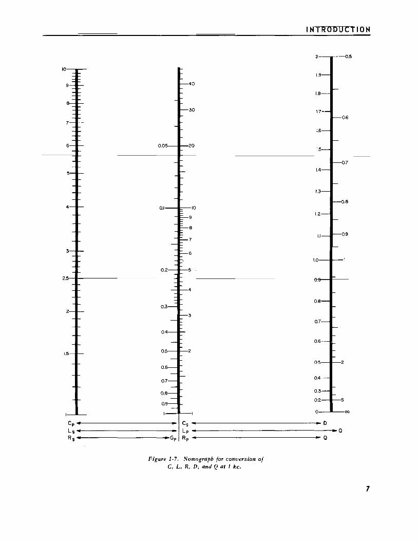
1.4 SERIES AND PARALLEL PARAMETERS.
An impedance that is neither a pure reactance nor a pure resistance can be represented at any specific frequency by either a series or a parallel combination of resistance and reactance. The values of resistance andreactance used in the equivalent circuit depend on whether a series or parallel representation is used. The equiv
alent circuits are shown in Figure 1-4. A nomograph for series-parallel conversion is given in Figure 1-7. The relationships between the various circuit elements are as follows:
I{ eststance and Inductance
1 1 +Q2 LP ; L = --L = (1 + D2 )L
1 +D2 P Q2 s s
Resistance and Capacitance
4
D2 1 1
Rs = 1 +D2 RP = 1 +Q2 RP (1 +Q2)GP
Ls
Rs
1c5
Rp Cp Lp Gp Rs
Figure 1-4. Equivalent circuits for complex impedance.
1.5 ACCURACY OF MEASUREMENTS.
Rp Gp
1.5. 1 CGRL ACCURACY AT 1 KC. The basic bridge accuracy is 0.1%. This is a function of the accuracy of the adjustment and stability of the bridge arms. The instrument is initially calibrated to an accuracy of ±0.05% or better and should hold the 0.1% accuracy for well beyond the two-year warranty period. A simple calibration check procedure is given in Section 5. 2.
The lowest-resistance (1-ohm) resistance ratio arm is the most difficult ratio arm to set ac.furately, is the most affected by switch and lead resistance, and has slightly poorer stability than the other arms. Therefore, the accuracy specification for the lowest impedance range for each bridge is 0. 2%.
The fixed error of ±0.005% of full scale or onehalf a digit on the counter read-out allows for backlash in the adjustment and for the limitations of linearity and resolution of the vernier rheostat. This fixed error gives an over-all accuracy at 1 kc (on all but the lowest range)

of 0.105% at full scale and 0.15% at one-tenth of full
scale. Therefore, the final balance should be made with
as many digits on the counter as possible.
1.5.2 TEMPERATURE COEFFICIENT. The over-all temperature coefficient of the instrument is less than 30 ppm/ °C This means that there may be a 0 03% change in reading for a temperature change of 10°C (50 °F). This change is usually negligible compared with the change in the unknown component for a similar tern-perature change. For the most accurate measurements, rne oriage ana co " <u uc ~uvw"u "''-
stabilized at a temperature near 23 ° C (7 3 ° F).
1.5.3 ADDITIONAL ERRORS FOR HIGH D CAPACI-TORS, LOW Q INDUCTORS, AND HIGH Q RESISTORS. The OQ dial adjustments used for phase balance on the C and L bridges are wire-wound rheostats. When lossy (high 0 or low Q) components are measured, the limited resolution of these adjustments prohibits balance of the c or L adjustment to its full resolution. A term of 0. 5%02 is added to the specifications to allow for this
effect, but somewhat better accuracy is possible with extreme care. Precision components generally have a low enough 0 or a high enough Q to make this term neg-ligible (see Figure 1-5).
10
'lJ /
O.OIL.--L---L--L---L----L_L-_ _,___....._ __ .._______,
100 Ike IOke FREQUENCY
Figure 1-5. Capacitance and inductance errors vs frequency.
IOOke
'INTRODUCTION
The Q adjustment for the Rs and Gp bridges consists of two decades of mica capacitors and a variable capacitor with infinite resolution. Losses in the mica capacitors appear as an R or G error when Q is relatively large, and the added error term of 0.1%Q is therefore necessa~y (see Figure 1-6).
100
10
~I
0.1
0.01 100
1 ff
r; I J v
jj VII
-;!; / TOTAL ERROR 0•1 ~ --~ w /~oo,(ffir tOTAL ER!OR 0• 0 ~ v;
I 011%/ 1/ I
I I 0002 (f.,)
2-i I I I
lL 1/ Ike IOke
FREQUENCY
Figure 1-6. Resistance and conductance errors vs frequency.
100
1.5.4 FREQUENCY ERRORS. The main cause of additional error on the C and L bridges at higher frequencies is the inductance of the bridge wiring in series with the standard capacitor, effectively increasing its value. This error is proportional to f2, and is accounted for in the added error term 0.001% (f/1 kc)2. This term, which amounts to a 0.1% error at 10 kc and a 0.4% error at 20 kc, is large enough to account for other smaller sources of error (see Figure 1-5).
For high D (low Q) measurements at high frequencies, there is an added error term due to the inductance of the OQ rheostats. This term is 0.10 (f/ 1 kc). (See Figure 2-7.) The series rheostat (Cs and Lp bridges) is phase-compensated to a large degree, but neverthe-
s

~---T_YP_E_1_6_08_-A __ IM_P __ E_D_A_N_C_E_B_R_I_D_G_E_I ----------------------------
less adds inductance in series with the standard capacitor. The inductance of the parallel rheostat (Cpand Ls bridges) is placed in parallel with the standard capacitor, and at high enough D values effectively reduces the capacitance of this bridge arm. The error on the Cp and Ls bridges is somewhat less, and these bridges have more useful D and Q ranges at high frequencies (see Figure 2-7).
A frequency-dependent error term is necessary for the resistance and conductance bridges because of a network built into the standard resistance arm to compensate for stray capacitance (refer to paragraph 4. 5). The effective resistance of this arm has one term proportional w £2 and ont: prgpertieaal te £4, req11iring the added error terms ±0.002 (f/1 kc)2 and ±0.000001 (f/1 kc)4. The first term is more important up to 45 kc, and adds an extra 0. 2% error at 10 kc and 0.8% error at 20 kc (see Figure 1-6).
1.5.5 RESIDUAL TERMINAL IMPEDANCE. The accuracy specifications are valid only if the effect of the residual terminal impedance of the UNKNOWN connection is considered. The residual resistance and capacitance can be easily measured and subtracted from the final measured value. At high frequencies somewhat more complicated corrections are necessary, particularly at the range extremes, and correction formulae are given in Table 2-5 .
1 56 D AND Q ACCURACY. The 5 percent term in the D and Q accuracy specifications for C and L measurements depends upon the tracking accuracy of the DQ
7i
rheostats with the dial calibration. The fixed terrrt, ±0.0005, depends upon the phase angle of each arm of
the bridge, and many compensating components are required to achieve this accuracy (refer to paragraph 4.5).
This specification of ±0.0005 holds for measurements made down to 1/20 of the full-scale CGRL counter reading. Below this reading, the phase angle of the vernier CGRL adjustment (R4), even though compensated for, can add additional DQ error. This could amount to an error of 0.001 at 1/100 of full scale and 0.005 at 1/1000 of full scale. The detector sensitivity is also a Hmiting factor here. Lower CGRL ranges should be used to achieve better D and Q accuracy.
At high frequencies the DQ error increases because the phase angles of the bridge arms increase with
f. Therefore, this fixed error term is 0.0005 1 ~c above
1 kc. At frequencies below 1 kc, the D accuracy cannot be improved because it is limited by the D of the standard capacitor.
The percent term in the Q accuracy for Rs and Gp bridges is ±2%, which is limited by the accuracy of the capacitance decades used for Q adjustment. The fixed term is ±0.0005 at 1 kc, just as in the L and C bridges, since the same phase angle considerations apply. However, for the Rs and Gp bridges, this term is ±0.0005
rk at higher and at lower frequencies. This gives ex
tremely good Q accuracy at low frequencies, but does not help 10 the measurement of the time constant (Q/ CtJ) of resi~tors, which is independent of frequency (except at very high frequencies).
IINTRODUCTION
2 0.5
0.6
0.7
0.8 0.1 10
9
8 0.9
7
6
0.2 5
4
0.3
3
0.4
0.5 2
2 0.6
0.7
0.8
5 0.9
I 0 00
Cp Cs D Ls Lp a Rs Gp Rp a
Figure 1-7. Nomograph for conversion of C, L, R, D, and Q at 1 kc.
7
~--T_Y_P_E_1_60_8-_A_I_M_P_E_D_A_N_C_E __ B_R_ID_G_E~I __________________________ ___
8
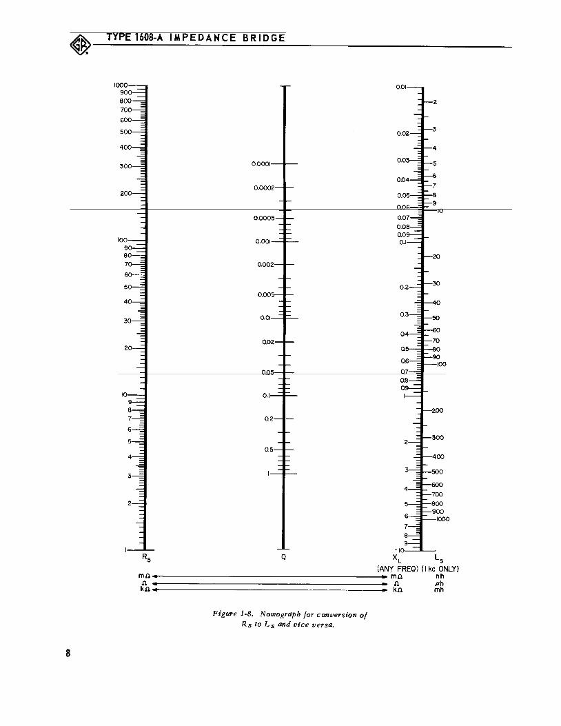
-10>-_._-Q XL Ls
(ANY FREQ) (I kc ONLY) mfi~-----------------------~ mfi nh fi fi Ph kn kfi mh
Figure 1-8. Nomograph for conversion of Rs to Ls and vice versa.

SECTION 2 OPERATING
2.1 INSTALLATION.
2.1.1 POWER CONNECTIONS. Connect the bridge to a suitable power source as indicated on the plate above the power receptacle on the rear of the instrument (115 or 230v, 50-60 cps). A three-wire power cord is supplied.
2.1.2 GROUNDING. The bridge should generally be operated with the bridge chassis grounded except in specific cases where the unknown component or a de bias supply should be grounded (refer to paragraphs 3.1. 5 and 3.5). The ground connection is made through the threewire power cord to the 3RD WIRE GROUND terminal on the rear of the instrument. This terminal should be connected to the adjacent CHASSIS terminal unless the bridge must be ungrounded. If the three•wire power cord is not used, this connection should be made externally.
2.1.3 MOUNT lNG. The instrument is available as either the Type 1608-AM, for bench mounting, or Type 1608-AR, for relay-rack mounting. The bench-mounting model is equipped with aluminum end frames, while the Type
1608-AR includes mounting brackets for relay-rack installation. Instructions for assembly accompany these brackets, which may be ordered separately (Type ZSU-6-7) to convert from bench to rack use.
Type ZSU-6-7 mounting brackets are of a uniquE
General Radio design which permits the instrument to be
pulled out on slides for service. Either chassis or cabinet
can be removed from the rack independently of the other.
2.2 INTERPRETATION OF •x• IN READ-OUT.
The main CGRL indication consists of up to five digits displayed in an in-line read-out. The three lefthand digits are controlled by the larger of ;he two concentric CGRL controls; the two right-hand digits are controlled by the smaller (vernier) control. To provide an overlapping transition from full-scale vernier reading (99) to the next higher coarse step, the vernier read-out extends beyond 99, up to 106. To avoid the ambiguity of two digits on the same counter, an X is used in place of the number 10. To interpret a reading containing an X, simply substitute 0 for the X and add 1 to the digit immediately to the left of the X. For example, 102X3 = 10303; 99X2 =10002.
The letter X is also used on two of the three Q
OPERATING PROCEDURE
PROCEDURE
dials used with the Rs and Gp bridges. Here again, substitute 0 in place of the X and add 1 to the digit to the left of the X. For example, .1X4 =.204; .2XX =.310.
Users may find it helpful to record measurement data exactly as it appears on the bridge read-out, in-cludmg any X' s that appear. In that way, any possible error in the interpretation of the X can be rechecked.
2.3 DC RESISTANCE MEASUREMENTS.
2.3.1 PROCEDURE. a. With the function switch (1, Figure 1-1) off,
check the NULL meter mechanical zero position, and, if necessary, center the pointer with the screw-driver adjustment on the meter.
b. Turn the DET SENS control almost fully counterclockwise.
. c. Set the BRIDGE SELECTOR switch to Rs for resistance measurements from 0 to 1.1 MD and Gp for resistance mea snrements above 1 MD and for conductance
measurements from 0 to 1.1 mho.
d. Connect the resistor to be measured to the UNKNOWN terminals.
e. Turn the function switch to lNT DC.
NOTE
As the function switch is rotated from OFF to INT DC, it passes through an undetented position where the circuit is operative but the meter sensitivity is greatly reduced. A pre
liminary balance may be made with the switch in this position instead of with the DET SENS control turned down.
f. Adjust the FULL SCALE RANGE switch and the concentric CGRL balancing controls for a zero (center) reading, and adjust the DET SENS and GEN LEV controls for increased sensitivity as necessary. A meter deflection to the right indicates that the unknown is larger than the indicated CGRL dial setting. For greatest accuracy the reading should have at least four digits showing. If not, turn to the next lower range.
g. The value of the UNKNOWN is read directly on the counter with the decimal point correctly located and the unit illuminated above. The meaning of an X indica
tor is explained in paragraph 2.2.
9

~---T_YP_E_l_6_08_-A __ IM_P_E_D_A_N_C __ E_B_R_I_D_G_E __________________________ ___
2.3. 2 ACCURACY. The accuracy of de resistance and conductance measurements is ±0.1%, ±0.005% of full sea e ( h. h I f h d. · ) ll b h W lC is ±1 2 0 t e ast lglt on a ut t e lowest R and highest G ranges as long as there is suf-ficient sensitivity. On the lowest R and highest G range the accuracy is limited by the sensitivity to ±1/2% ±1 m.O,
For low-resistance measurements, short, heavy leads should be used as connections to the unknown component. Measure the zero resistance of the lead!; and terminals by connecting the free ends together, and subtract this amount from the bridge reading with the un-known 1n place. For best connection to the bridge, screw the binding post hard enough to notch the wire inserted in the hole.
2.3.3 INTERNAL VOLTAGE APPLIED TO THE UN-KNOWN. There are three internal de supplies, each hav-ing a limiting resistor to limit the available power to 1/2 watt or less to avoid damage to the bridge compon-en~s or to the unknown. They are all controlled by the GEN LEV panel control. The lowest voltage supply, ap-proximating 3. 5 volts open circuit, is applic:d "horizon-
tally" to the bridge (see Figure 1-3) and the 35-volt and 350-volt supplies are applied "vertically". The FULL SCALE RANGE switch selects the optimum supply for each range as given in Table 2-1.
Because of the limiting resistor, the maximum vouage app1iea ro rne unKnown is usuauy or mucn re:s:s than the open-circuit value. Figure 2-1 shows the ac-tual voltage applied to any unknown resistor when meas-ured on the R bridge (with a 115-volt line voltage).
EIA specifications for testing different types of resistors are summarized in Tables 2-2 and 2-3. Figure 2-1 shows that these standard voltages can be supplied from the internal power supplies over most of the resis-tance range. For low-resistance measurements the GEN LEV control can be set for the desired test voltage by use of a high-impedance de voltmeter connected directly w the UNKNOWN terminals. For high-resistance meas-urements, where the voltage is applied vertically, the
ratio between the voltage across the unknown and that across the whole bridge is fixed over each range at null and therefore the voltmeter can be placed across the bridge input (LOW UNKNOWN terminals to chassis) and the GEN LEV control set to give the "bridge voltage" given in Tables 2-2 and 2-3.
2.3.4 EXTERNAL DC DETECTOR. The internal de supplies and the internal detector permit measurements from 1 ohm to 1 megohm to 0.1% when the GEN LEV and DET SENS controls are at maximum. If accurate measurements beyond this range are desired or if it is necessary to make measurements at lower voltages, an exter-
10
000 I
I I
I I
~;-k """ TO IM IOOv
If 100
I ...,.,.,. ~ I v I 1/f IOk TO lOOk 30 v r
'Y i""""""" elk TO IOk 10 v
10 , I I I I ~ -v d 100.0. TO lk .0. 2.5 TO 3 v
I I I
li ~~~ -I ...,,- ,oo~ o:oL~ -I ~~o~,o~ I I / // b 1.0. TO 10.0. I ~
/ [; --~ ,.,.,... -'t ~
)~ Va 0.1 TO 1.0.
o.1 I I
/ V"
I I Jy
0.01 0
I I I I 2 3 4 5 6 7 8
Figure 2-1. De voltage applied to unknown resistor (115-v line).
10

OPERATING PROCEDURE
TABLE 2-1 DC SOURCE AND DETECTOR CONNECTIONS
FULL SCALE RANGE 1100 mD j 11 D 11100 1100 D j 11 kD 110 kD f 1100 kD
Rs VERTICAL METER MVS HVS
Bridge HORIZONTAL LVS METER
GP FULL SCALE RANGE 1100nU In flu !no flu 1100 fLU In mU 110 mU j1100 mU
Bridge VERTICAL HVS
HORIZONTAL METER MVS
HVS HIGH-VOLTAGE SUPPLY - 35G" gp€:n-Giwdt MVS MEDIUM-VOLTAGE SUPPLY 35v open-circuit LVS LOW-VOLTAGE SUPPLY 3.5v oyen-circuit
TABLE 2-2 EIA STANDARD TEST VOLTAGES
Fixed Composition Resistors (RS172)
METER
LVS
RESISTANCE BRIDGE RANGE EIA TEST VOLTAGE BRIDGE VOLTAGE*
2.7-9.9 D
10-99 D
100-999 D
1000-9999 D
10- 99k D
100kD-1MD
1 MD-up
RESISTANCE
less tha"n 10 D
10- 99 D
100- 999 D
10oo- 9999 D
10- 99kD
100kD- 1MD
1MD- up
Rs
Rs
Rs
Rs
Rs
Rs
GP
llD 0. 5 - 1 v
llOD 0.5 - 1 v
llOOD 2.5 - 3 v
llkD 8- 10 v
llOkD 24 - 30 v
llOOkD 80- 100v
1 n U 80- 100 v
TABLE 2-3 EIA STANDARD TEST VOLT AGES
Fixed Film Resistors (RS-196)
Low-Power Wire-Wound Resistors (REC-117 up to 9999 D)
BRIDGE RANGE EIA MAX VOLTAGE
Rs 11.1"2 0.3 v
Rs 1100 h
Rs 1100 D 3v
Rs llkD 10v
Rs llOkD 30v
Rs 1100kD 100v
Gp 1 nU 100v
•• •• 19.2- 23v
13.4-16.7v
25.6- 32 v
81 - 101 v
81 - 101 v
MAX BRIDGE VOLTS*
•• •• 23v
16.7 v
32v
101 v
100v
* This is the voltage from the LOW UNKNOWN terminal to chassis. In the EXT DC position, this is also the voltage at the EXT GEN terminals.
* * This voltage varies with the resistance of the unknown (see paragraph 4. 3).
11

~---TY_P_E_l_60_8_-A __ IM_P_E_D_A_N_C_E __ B_R_I_D_G_E __________________________ ___
EXT METER
(a)
EXT METER
TO BRIDGE
(b)
EXT METER
~· (c)
Figure 2-2. External meter connections.
nal detector with increased sensitivity can be used. The external detector can be connected in series with the internal meter, in parallel with the meter, or in place of the meter by appropriate connection to the EXT METER CONNECTIONS on the rear of the instrument as shown in Figure 2-2.
2.3.5 .EXTERNAL DC SUPPLY. If higher voltage is required on the unknown resistor, an external supply may be used. The EXT GEN terminals are connected directly across the vertical bridge diagonal in the EXT DC position of the function switch and the detector is across the horizontal diagonal on the top four ranges. Be careful not to exceed the maximum voltage or current given in Table 2-4 in order to avoid damage to the bridge components.
When an external supply or detector is used, the measurement procedure is the same as that with the internal supply and detector except that the GEN LEV
control does not control the level of an external supply and the OET SENS control does not control the sensitivity of an external detector.
2.4 AC MEASUREMENTS USING INTERNAL GENERATOR.
2.4.1 1-KC CAPACITANCE MEASUREMENT.
2.4. 1.1 Procedure.
a. Set the GEN LEV control fully clockwise.
b. Set the BRIDGE SELECTOR to: Cs - if the series capacitance is desired and D is less
than 1. Cp - if the parallel capacitance is desired and D is be
tween 0.02 and 2.
(Note: Cs = Cp within 0.1% if 0( 0.03.) Gp - if D is greater than 2 (measure as a conductance,
Cp = Q~e_).
TABLE 2-4
MAXIMUM EXTERNAL DC BRIDGE VOLTAGE AND CURRENT
BRIDGE RANGE E MAX I MAX TERMINALS
Rs llOOm.O 1.4v 710ma BIAS
Rs 11.12 4.5 v 223ma BIAS
Rs 110.12 14.2v 71ma BIAS
Rs 1100.0 22v 17.2ma EXT GEN
Rs llkD 71v 17.2ma EXT GEN
Rs llOkD 223v 17.2ma EXT GEN
Rs llOOkD 400v 17.2ma EXT GEN
GP lOOOnU 400v 17.2ma EXT GEN
12
c. Set the function switch to INT AC.
d. Connect the unknown capacitor to the UN-
KNOWN terminals.
e. If the proper range setting of the FULL SCALE RANGE is not known, set the concentric CGRL controls
for a reading somewhere near 5000, adjust the DET SENS control for an upscale meter reading and set the FULL SCALE RANGE switch for a minimum meter de
flection.
f. Adjust the concentric CGRL controls and the DQ control for minimum meter deflection. The DET
SENS eeatrel may have te be readjust€:d t9 gi"€: gr€:at€:r sensitivity as balance is approached.
g. The capacitance of the unknown is indicated
directly on the counter readout with the correct decimal
point and unit illuminated. The D of the unknown is in
dicated directly on the illuminated scale on the DQ dial.
The meaning of an X indicator is explained in para
graph 2.2.
2.4.1.2 Accuracy. The accuracy of the C reading is ±0.1% ·of the reading ±0.005% of full scale (which is ± 1/2 of the last digit) on all but the highest capacitance range, where the accuracy is ±0.2% of the reading ±0.005% of full scale. On the lowest C range it is necessary to subtract the residual ("zero") capacitance of the bridge terminals, approximately 0. 25 pf, from the reading to determine the correct value of the unknown capacitor. If external leads are used to connect the unknown, this zero capacitance is increased and should be subtracted from the reading. The error caused by capacitance between the terminals and leads may be removed by means of a three-terminal shielded capacitance measurement (refer to paragraph 3.2).
The residual resistance and inductance of the bridge have negligible effect on the C or D accuracy except for a slight D error on the highest C range (D error = 0.006 when Cx = 1000 pf). However, if long leads are used when measurements are made on large capacitors, a correction for the lead resistance and inductance may be necessary. The correction terms are given in Table 2-5.
When capacitors with high D's are measured, an additional error of ±(0.5%) o2 is added to the specification (refer to paragraph 1.5.3). This error is negligible when Dis less than 0.2.
2.4.2 1-KC INDUCTANCE MEASUREMENT.
2.4.2. 1 Procedure.
a. Set the GEN LEV control fully clockwise.
OPERATING PROCEDURE
Note: For some iron-cored inductors the inductance measured will depend upon the excitation level (refer to paragraph 2.4.5.4).
b. Set the BRIDGE SELECTOR to~ L s - if the series inductance is desired and Q is be
tween 0.5 and 50. Lp - if the parallel inductance is desired and Q is greater
than 1. (Note: Ls = Lp within 1% if Q )32)
Rs - if Q is less than 0. 5 (measure Rs and Q;
Ls =~ refer to paragraph 2.4.3). liJ
c. Set the function switch to INT AC.
d. Connect the inductor to be measured to the UN
KNOWN terminals.
e. If the proper range setting of the FULL SCALE RANGE is not known, set the concentric CGRL controls for a reading somewhere near 5000, adjust the DET
SENS control for an upscale reading, and set the FULL SCALE RANGE switch for a minimum meter deflection.
f. Adjust the concentric CGRL controls and the DQ control for minimum meter deflection. The DET SENS control may have to be readjusted to give greater
sensitivity as balance is approached.
g. The inductance of the unknown is indicated directly on the counter readout with the correct decimal point and unit illuminated. The Q of the unknown is in
dicated directly on the illuminated scale of the DQ dial.
The meaning of an X indicator is explained in paragraph
2. 2.
2.4.2.2 Accuracy. The accuracy of the L reading is ±0.1% of the reading ±0.005% of full scale (which is ± 1/2 of the last digit) on all but the lowest ranges, where the accuracy is ±0.2% of the reading ±0.005% of full scale. When Q is low there is an additional error
of 0.5% ~2, which is negligible when Q is approximately
5 or higher.
On the lowest range, the residual inductance of the binding posts (0.14 fLh) must be subtracted from the reading in order to obtain full accuracy. If external leads are used to connect the unknown inductor to the bridge, then the residual inductance should be measured and subtracted from the L reading. To measure this lead inductance, short the leads together, mea sure the imped-
ance on the Rs bridge, and calculate Ls = Q:s. Be
careful to keep the lead configuration the same for the residual inductance measurement and the total inductance measurement, since an increase in the area between the leads would increase the residual inductance.
13

~---TY_P_E_1_60_8_-A __ IM_P_E_D_A_N_C_E __ B_R_I_D_G_E ____________________________ _
The residual resistance of the bridge is approximately 0.9mD. This can cause a small Q error when Lx is small. If long leads are used, the Q error becomes more important {see Table 2-5). The residual bridge capacitance of 0.25 pf can cause an L error when Lx is
very large. However, this capacitance is usually negligible compared with the capacitance of a large inductor. Long leads to the inductor may appreciably change
the total capacitance. The corrections for these lead effects are given in Table 2-5.
14
When inductors with low Q' s are measured, an ad
ditional error term of ±0. 5% ~ 2
is added to the specifi-
cations (refer to paragraph 1. 5. 3). This error is negligible when Q is greater than 5.
TABLE 2-5 CORRECTIONS FOR ERRORS CAUSED BY TERMINAL AND LEAD IMPEDANCES
(Add or subtract from the measured value as indicated.)
Measured Series Resistance Series Inductance Parallel Capacitance R0 =0.9mD +leads L0 =0.14 ,uh +leads C0 = 0.25 pf + leads
Cs NO ERROR -u:2LoCx2 -CoO -Dx2)
D -u.;CxRo -w2LoCxDx co
+ D - (1 + D 2) X CX X
cp +2RoDxu.;Cx2 -w2LoCx2(1- Dx2) -Co
D -wCxRo(l + Dx2) -w2LoCxDx(l + Dx2) +Co Dx
Cx
GP +Gx2Ro(l + Qx2) +u.;2L 2G 3(1- ~) o x u.;GxLo
NO ERROR
Q +QxGxRo(l- Qx 2) +wL0 Gx {1 + Q/) -wC0
Gx
Rs 2Qx
-Ro NO ERROR +u.;2 C 2R 3(1- --) 0 X u.;CORX
Ro _ cvL0 + u.; Co Rx ( 1 + Qx 2) Q QxR
Rx X
Ls NO ERROR -Lo 1
-w2C L 2(1- -) o x Qx2
Q 2 Ro - Lo 1
+Qx wL LX
Qx +w2CoLx(Qx +Qx) X
2R0 1 LP +- -L (1- -) -u;2 CoLx 2
Qu.; o Qx2
Q Ro Lo 1
+ -- (1 + Q2) - (Qx + Q} +w2CoLxQx wLx LX
2.4.3 1-KC RESISTANCE AND CONDUCTANCE MEASUREMENTS. 2.4.3.1 Procedure.
a. Set the GEN LEV control fully clockwise.
b. Set the BRIDGE SELECTOR to: Rs - if series resistance is desired, and the resistance of the unknown is between 0 and 1 MD or if the unknown is inductive. Gp - if parallel conductance is desired, and the conductance of the unknown is between 0 and 1 mho or if the
unknown is capacitive. (Refer to Section 3.8 for RP measurement.)
(Note: Any resistor small enough to require use of the Rs bridge because of value will be inductive; likewise, any resistor large enough to require use of the Gp bridge will be capacitive. In the range between 1 D and 1 MD the phase of the resistor will determine which bridge is required unless Q is small enough to permit use of either bridge. Rs may be calculated from Gp, and
vice versa, from the formula Rs = _........., __ _ (1 t Q2) Gp
c. Set the function switch to INT A C. d. Connect the unknown resistor to the UNKNOWN
terminals. e. If the proper range setting of the FULL SCALE
RANGE is not known, set the concentric CGRL controls for a reading somewhere near 5000, adjust the DET SENS control for an upscale meter reading and set the FULL SCALE RANGE switch for a minimum meter deflection.
f. Adjust the concentric CGRL controls and the three Q controls for the be£t minimum meter deflection. The DET SENS control may have to be readjusted to give greater sensitivity as balance is approached.
g. The resistance or conductance of the unknown is indicated directly on the counter readou~ with the decimal point and unit illuminated. The Q of the unknown is read directly on the Q readout and is inductive or capacitive as indicated by the lights (unless the Q balance is less than 0, in which case the opposite is true). Note the. decimal point in the first (coarsest) adjustment, which makes major divisions on the vernier dial steps of 0.00 1. The meaning of an X indicator is explained
in paragraph 2. 2.
2.4.3.2 Accuracy. The accuracy of the R or G reading is ±0.1% of the reading ±0.005% of full scale (which is ± 1/2 of the last digit) on all but the lowest R and highest G ranges where the accuracy is ±0.2% of the reading ±0.005% of full scale.
On the lowest R range the residual resistance of the bridge (approximating 0.9 mD) should be subtracted
OPERATING PROCEDURE
from the measured resistance. Use short, heavy leads to connect the unknown resistor, measure the resistance of these leads by connecting the free ends together, and subtract this value from the measured value.
Residual inductance and capacitance affect only the Q of the resistor. Corrections for these effects are given in Table 2-5. When resistors with high Q' s are measured, an additional error term of 0.1%Q is added to the specification (refer to paragraph 1. 5. 3). This term is practically negligible when Q is less than 0.2.
2.4.4 MEASUREMENTS USING INTERNAL GENERATOR AT FREQUENCIES OTHER THAN 1 KC. If an os-cillator-detector tuning unit other thaa the 1 kc uait usually supplied is used, the operating procedure is the same as for 1-kc measurements, but the accuracy specifications and D and Q ranges are the same as those for an external generator at the same frequency (refer to Section 2. 5). The plug-in unit gives the DQ multiplier required for the various bridges so that it does not have to be calculated (refer to paragraph 2. 5.1).
2.4.5 NOTES ON AC MEASUREMENTS.
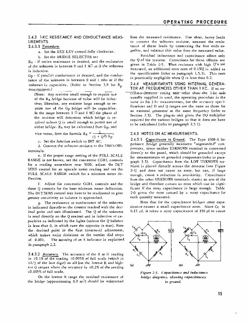
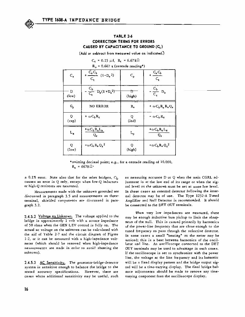
2.4.5. 1 Capacitance to Ground. The Type 1608-A Impedance Bridge generally measures "ungrounded" components, since neither UNKNOWN terminal is connected directly to the panel, which should be grounded except for measurements on grounded components (refer to paragraph 3.5). Capacitance from the LOW UNKNOWN terminal is placed directly across the detector (see Figure 2-3) and does not cause an error, but can, if large enough, cause a reduction in sensitivity. Capacitance from the other UNKNOWN terminals shunts an arm of the bridge and therefore causes an error which can be significant if the stray capacitance is large enough. Table 2-6 gives the error caused by a stray capacitance for each quantity measured.
Note that for the capacitance bridges stray capacitance causes a small capacitance error. Since Ct is 0.15 p.J, it takes a stray capacitance of 150 pf to cause
Figure 2-3. Capacitance and inductance bridge diagrams, showing capacitances
to ground.
15
~---T_Y_PE __ 16_D_8-_A_I_M_P_E_D_A_N_C __ E_B_R_I_D_G_E_' ____________________________ ___
TABLE 2-6 CORRECTION TERMS FOR ERRORS
CAUSED BY CAPACITANCE TO GROUND (Cb)
(Add or subtract from measured value as indicated:)
Cc = 0.15 f.J..f, Rc = 6.67kD
R 0 = 0.667 x (centade reading*)
CxCb Cs +---
ct (1-Dx 2)
cb u - Ux\J. ·ux·J
(low) ct
GP NO ERROR
Q + cuCbRt (cap)
Ls +UJCbRnLx
Qx
Q -u.;CbRn Qx 2
(low)
*omittin g decimal p oint· e. g' R0 = 66700•
a 0.1% error. Note also that for the other bridges, Cb causes an error in Q only, except when low-Q inductors or high-Q resistors are measured.
Measurements made with the unknown grounded are discussed in paragraph 3.5 and measurements on threeterminal, shielded components are discussed in para
graph 3.2.
2.4.5. 2 Voltage on Unknown. The voltage applied to the bridge is approximately 1 volt with a source impedance of 50 ohms when the GEN LEV control is fully on. The actual ac voltage on the unknown can be calculated with the aid of Table 2-7 and the circuit diagram of Figure 1-2, or it can be measured with a high-impedance voltmeter (which should be removed when high-impedance measurements are made in order to avoid shunting the unknown).
2.4.5.3 AC Sensitivity. The generator-bridge-detector system is sensitive enough to balance the bridge to the stated accuracy specifications. However, there are cases where additional sensitivity may be useful, such
16
cp CxCb
+--Cc
cb u - Ux
(high) ct
Rs + cuCb~ RxQx
Q - cuCbRn (in d)
+cuCbRnLx LP
Qx
Q -cuCbRn Qx2 (high)
for a centade readin g of 10.000
as measuring accurate D or Q when the main CGRL adjustment is at the low end of its range or when the signal level on the unknown must be set at some low level. In these cases an external detector following the internal detector may be of use. The Type 1232-A Tuned Amplifier and Null Detector is recommended. It should be connected to the DET OUT terminals.
When very low impedances are measured, there may be enough inductive hum pickup to limit the sharpness of the null. This is caused primarily by harmonics of the power-line frequency that are close enough to the tuned frequency to pass through the selective detector. In some cases a small "beating" on the meter may be noticed; this is a beat between harmonics of the oscillator and line. An oscilloscope connected to the DET OUT terminals may be used to advantage in such cases. If the oscilloscope is set to synchronize with the power line, the voltage at the line frequency and its harmonic
will be a fixed display pattern and the bridge output signal will be a time-varying display. The final bridge balance adjustments should be made to remove any timevarying component from the oscilloscope display.

OPERATING PROCEDURE
TABLE 2-7 BRIDGE COMPONENT RATINGS
FULL-SCALE RANGE setting Ra Ra Max Ra Max
c G R L Value Voltage Current
1100 fl£ llOOmU 1100mD 1100 flh 1D 0.71 v 710ma
110 fl£ llOmU 11D llmh 10D 2.2v 220ma
11 fl£ 11mU llOD 110mh lOOD 7.1 v 71ma
1100 nf 1100 flU 11000 1100mh lkD 22v 22ma
110nf 110 flU 11kD llh 10kD 71v 7.1ma
11 nf 11 flU 110kD 110h 100kD 220v 2.2ma
llOOpf llOOnU 1100kD llOOh 1MD 500v 0.7ma
CENT ADE - Rn (R1): 30 rna STANDARD RESISTOR Rt (R3): 58v, 86ma.
STA...~DARD CAPACITOR, Ct (C1): 600v peak (425v rms). DETECTOR INPUT CAPACITOR (C556): 400 v peak (280 v rms).
2.4.5.4 Effect of Level an Iron-Cored Inductor Measurements. Iron-cored inductors are nonlinear devices whose inductance depends on the level of the applied voltage. If measurements are to be repeatable, the signal level must be specified. The "initial permeability" inductance, or inductance at "zero level", is often used as a reference (as on General Radio Type 1481 Inductors). To obtain this value, plot L vs applied voltage and extrapolate to zero voltage. The GEN LEV control permits such measurements, and it 1s often useful to make a level change in order to see if the unknown inductance depends on the signal level.
2.4.6 DIFFERENCES BETWEEN AC AND DC RESISTANCE MEASUREMENTS.
2.4.6.1 General. The ac resistance bridge of the Type 1608-A Impedance Bridge provides a means for extending the range and sensitivity of resistance measurements over that possible with de, without using a higher applied voltage or a sensitive de amplifier. The ac resistance of a resistor can differ from the de value for a number of reasons. However, most of those are negligible at 1000 cps, and in some cases the use of ac avoids undesirable effects that can cause errors in de
!Ileasurement.
2.4.6.2 Frequency Effects.
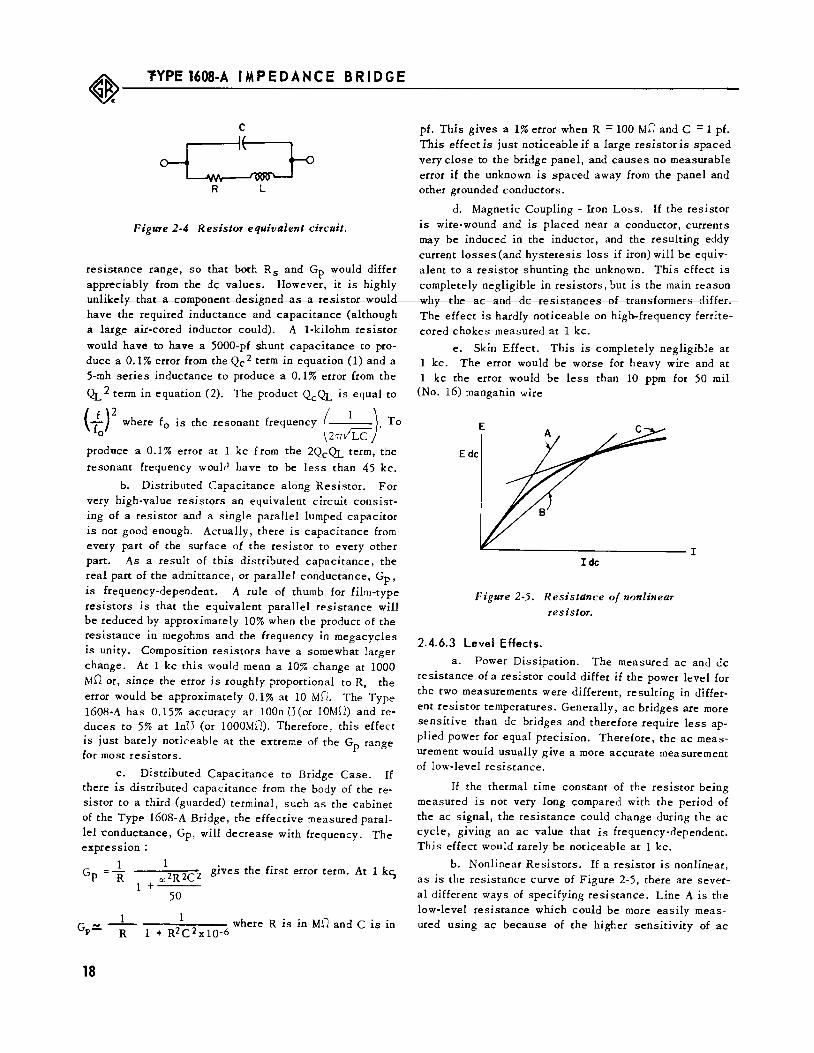
a. Series Inductance and Parallel Capacitance. At audio frequencies almost all resistors except those
of very high value (see b and c below) can be accurately represented by the equivalent circuit of Figure 2-4. In this circuit the resistor is a pure resistance and equal to the low-level de value unless some other effect is
appreciable. If we let QL =~and Qc = UJRc, then the R
effective series resistance of this equivalent circuit is
R (1)
and the effective parallel conductance is
1 1 Gp =R X 1 +QL2
(2)
Low-valued resistors have a completely negligible Qc but QL can become appreciable, particularly for wirewound resistors. Since Qc is negligible, the value of Rs is equal to the de value, but the value of Gp is not equal
1 to Rdc. However, on the Type 1608-A, if the resistor is
inductive, it can be balanced only on the Rs bridge, where there is no error.
High-valued resistors have a negligible QL but Qc is appreciable even if the parallel capacitance is small. If the unknown resistor is capacitive, it can be measured only on the Gp bri~ge where there is no error due to lumped parallel capacitance.
It is conceivable that both .QL and Qc could be large enough to have an appreciable effect in the middle
17
~---~_YP_E_1_60_8_-A __ IM_P_E_D_A_N_C_E __ B_R_I_D_G_E ____________________________ _
c
R L
Figure 2-4 Resistor equivalent circuit.
resistance range, so that both Rs and Gp would differ appreciably from the de values. However, it is highly nolikely that a cornpooer:Jt desigoed as a resistor would have the required inductance and capacitance (although a large air-cored inductor could). A 1-kilohm resistor
would have to have a 5000-pf shunt capacitance to produce a 0.1% error from the Qc 2 term in equation (1) and a 5-mh series inductance to produce a 0.1% error from the
Qr. 2 term in equation (2). The product QcQL is equal to
{f)2 where f0 is the resonant frequency (
1 )·To 0 2~/LC:
produce a 0.1% error at 1 kc from the 2QcQL term, the
resonant frequency woulrl have to be less than 45 kc.
b. Distributed Capacitance along Resistor. For very high-value resistors an equivalent circuit consisting of a resistor and a single parallel lumped capacitor is not good enough. Actually, there is capacitance from every part of the surface of the resistor to every other part. As a result of this distributed capacitance, the real part of the admittance, or parallel conductance, Gp, is frequency-dependent. A rule of thumb for film-type resistors is that the equivalent parallel resistance will be reduced by approximately 10% when the product of the resistance in megohms and the frequency in megacycles is unity. Composition resistors have a somewhat larger change. At 1 kc this would mean a 10% change at 1000 MD or, since the error is roughly proportional to R, the error would be approximately 0.1% at 10 MD. The Type 1608-A has 0.15% accuracy at lOOn (J(or 10M.0) andreduces to 5% at 1nU (or 1000M.0). Therefore, this effect is just barely noticeable at the extreme of the Gp range for most resistors.
c. Distributed Capacitance to Bridge Case. If there is distributed capacitance from the body of the resistor to a third (guarded) terminal, such as the cabinet of the Type 1608-A Bridge, the effective measured parallel 'Conductance, Gp, will decrease with frequency. The expression :
1 Gp = R "' 2R 2C 2 gives the first error term. At 1 kc,
1 + 50
1 1 where R is in MD and C is in Gl>~ R 1 + R2C2x10-6
18
pf. This gives a 1% error when R = 100 MD and C = 1 pf. This effect is just noticeable if a large resistor is spaced very close to the bridge panel, and causes no measurable error if the unknown is spaced away from the panel and other grounded conductors.
d. Magnetic Coupling - Iron Loss. If the resistor is wire-wound and is placed near a conductor, currents may be induced in the inductor, and the resulting eddy current losses (and hysteresis loss if iron) will be equivalent to a resistor shunting the unknown. This effect is completely negligible in resistors, but is the main reason why the ac aad de resistaaces ef traasfermers differ. The effect is hardly noticeable on high-frequency ferritecored chokes measured at 1 kc.
e. Skin Effect. This is completely negligible at 1 kc. The error would be worse for heavy wire and at 1 kc the error would be less than 10 ppm for 50 mil
(No. 16) mangallin wire
Ide
Figure 2-5. Resistance of nonlinear resistor.
2.4.6.3 Level Effects.
a. Power Dissipation. The measured ac and de resistance of a resistor could differ if the power level for the two measurements were different, resulting in different resistor temperatures. Generally, ac bridges are more sensitive than de bridges and therefore require less applied power for equal precision. Therefore, the ac measurement would usually give a more accurate measurement of low-level resistance.
If the thermal time constant of the resistor being measured is not very long compared with the period of the ac signal, the resistance could change during the ac cycle, giving an ac value that is frequency-dependent. This effect would rarely be noticeable at 1 kc.
b. Nonlinear Resistors. If a resistor is nonlinear, as is the resistance curve of Figure 2-5, there are several different ways of specifying resistance. Line A is the low-level resistance which could be more easily measured using ac because of the higher sensitivity of ac

bridges. Line B is the de resistance at a given voltage,
Edc· Another value, line C, is the incremental value using a low-level ac signal superimposed on a de bias (refer to paragraph 3.1.3).
c. Thermal Voltages. If the two connections to
the unknown are not at the same temperature, a small de thermocouple voltage is induced that can cause an error in de measurements. The error varies with the applied de level.
2.5 AC MEASUREMENTS WITH EXTERNAL GENERATOR
2.5.1 PROCEDURE. The procedure for making measurements with an external generator is the same as that with the internal 1-kc oscillator except for the following:
a. Connect the external oscillator to the instn!ment as described in paragraph 2.5.3. (Note that the GEN LEV control does not control the level of an externally applied signal.)
b. Set the function switch to EXT AC (this con
nects the EXT GEN terminals to the bridge input transformer and switches the detector to a flat frequency
characteristic).
c. Multiply the D and Q readings by the following factors to determine the value at the test frequency, f.
Bridge Multiplying Factor
Cs LOW D f/1 kc
Cp HIGH D 1 kc/f
Gp Q f/1 kc
Rs Q f/1 kc
Ls LOW Q f/1 kc
Lp HIGH Q 1 kc/f
If the presence of a nonlinear unknown causes distortion in the detector, the best meter null may not give the correct value. Also, excess noise may limit the null ob
tainable. Earphones (connected to the DET OUT terminal) are helpful in distinguishing a null at the fundamental frequency, or an external selective amplifier, such as the Type 1232-A Tuned Amplifier and Null Detector, can be used. In extreme cases, distortion or noise could have enough amplitude to overdrive the in
ternal detector when the function switch is at EXT AC and could thus give erroneous readings on a selective detector connected to the DET OUT terminals. In such cases, the external detector should be connected from the LOW UNKNOWN terminal to panel ground.
2.5.2 ACCURACY. The accuracy of measurements made with an external generator is the same as that with the internal oscillator except that the following frequency
dependent terms are added to the specifications:
OPERATING PROCEDURE
L and C measurements:
±0.001% ( _!__) 2, f \l kc ±0. 1% D 1 kc
R and G Measurements:
±0.002% ( _f_) 2
' ±0.000001 (-f- )4
1 kc 1 kc
These extra terms and the total error are shown
diagrammatieally ia Figures 1 5 aad 1 6. Ia erder te achieve this accuracy, it is necessary to correct for the effect of the residual impedances of the terminals and connecting leads, which become more important at higher
frequencies (refer to paragraph 2.5.7). For Rs and G measurements there is a slight error if more than ~ volts is applied by the external generator.
The percent D or Q error is 5% for L and C measurements at any frequency, but the fixed error term be-
comes 0.0005 1 ~cor 0.0005, whichever is larger. For
Rs and Gp measurements the Q accuracy ls ±2% ±0.0005 f/1 kc. For large applied voltages, a somewhat larger Q error may be caused by saturation of the phase-compensating inductor. This error may be as large as 0.005 f/1 kc.
2.5.3 CONNECTION OF EXTERNAL GENERATOR. In most cases when an external generator is used it should be connected to the EXT GEN terminals. In this connection, the external generator is connected directly to the internal bridge transformer when the function switch is in the EXT AC position, and the low generator terminal is connected to the bridge chassis (which should be grounded; refer to paragraph 2.1. 2). A second ground connection to the generator should be avoided.
If the external generator can be overdriven when connected to a low-impedance load, it is generally desirable to place a resistor in series with the ungrounded generator connection to the bridge. This resistor should be large enough to prevent distortion even when the bridge input is short-circuited. The bridge input impedance at the EXT GEN terminals is a minimum of 30 ohms
(resistive) at 1 kc when the bridge is set to measure a short circuit on the UNKNOWN terminals. This is shunted by the inductance of the primary of the bridge transformer, which is approximately 0.25 henry.
In some cases where more input power is required, particularly in measurements of low impedance, a match
ing transformer between generator and bridge is useful. This tran·sformer need not be shielded.
When the desired bridge voltage is higher than can
19
~---T_Y_PE __ 16_68_-A ____ I_M_P_E_D_A_N_C_E_B_R_I_D_G_E_' -----------------------------------------
be applied by the internal bridge transformer, the generator can be connected directly in the bridge circuit by
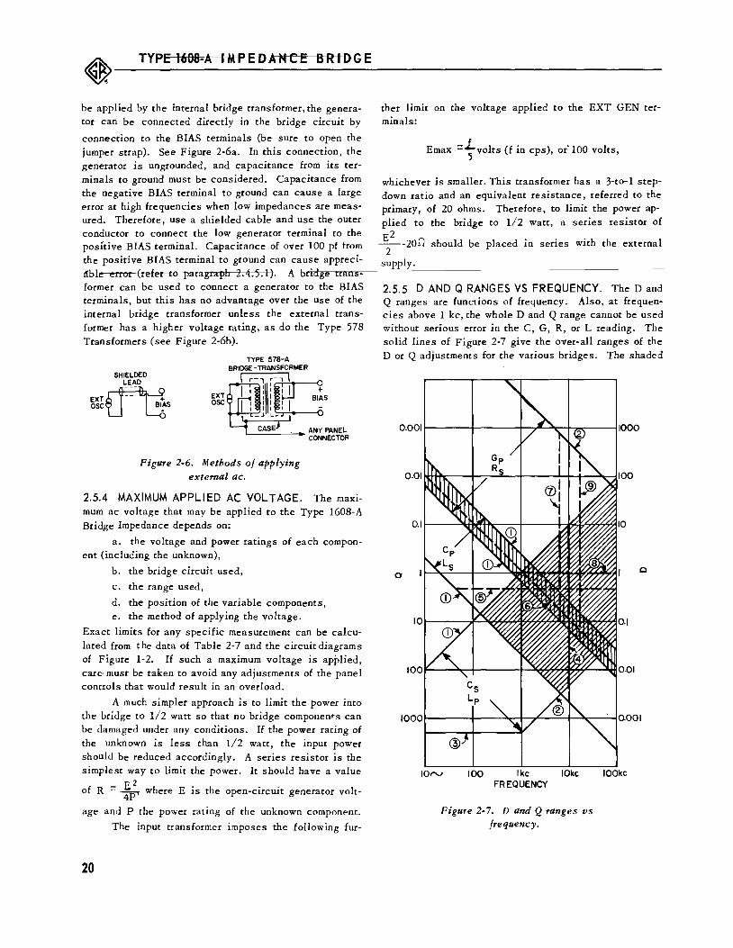
connection to the BIAS terminals (be sure to open the jumper strap). See Figure 2-6a. In this connection, the generator is ungrounded, and capacitance from its terminals to ground must be considered. Capacitance from the negative BIAS terminal to ground can cause a large error at high frequencies when low impedances are measured. Therefore, use a shielded cable and use the outer conductor to connect the low generator terminal to the positive BIAS terminal. Capacitance of over 100 pf from the positive BIAS terminal to ground can cause appreci-dble error (refer to paragraph 2.4.5.1). A bridge transformer can be used to connect a generator to the BIAS terminals, but this has no advantage over the use of the internal bridge transformer unless the external transformer has a higher voltage rating, as do the Type 578 Transformers (see Figure 2-6b).
SHIELDED
EXT~ OSCL_j ~S
EXT osc
Figure 2-6. Methods of applying external ac.
2.5.4 MAXIMUM APPLIED AC VOLT AGE. The maximum ac voltage that may be applied to the Type 1608-A Bridge Impedance depends on:
a. the voltage and power ratings of each compon-ent (including the unknown),
b. the bridge circuit used,
c. the range used,
d. the position of the variable components, e. the method of applying the voltage.
Exact limits for any specific measurement can be calculated from the data of Table 2-7 and the circuitdiagrams of Figure 1-2. If such a maximum voltage is applied, care· must be taken to avoid any adjustments of the panel controls that would result in an overload.
A much simpler approach is to limit the power into the bridge to 1/2 watt so that no bridge components can be damaged under any conditions. If the power rating of the unknown is less than 1/2 watt, the input power should be reduced accordingly. A series resistor is the simplest way to limit the power. It should have a value
of R = 4 where E is the open-circuit generator volt-4P
age and P the power rating of the unknown component.
The input transformer imposes the following fur-
20
ther limit on the voltage applied to the EXT GEN terminals:
Emax =+volts (fin cps), oi 100 volts,
whichever is smaller. This transformer has a 3-to-1 stepdown ratio and an equivalent resistance, referred to the primary, of 20 ohms. Therefore, to limit the power applied to the bridge to 1/2 watt, a series resistor of E2
---20.0 should be placed in series with the external 2
supply.
2.5.5 D AND Q RANGES VS FREQUENCY. The D and Q ranges are functions of frequency. Also, at frequencies above 1 kc, the whole D and Q range cannot be used without serious error in the C, G, R, or L reading. The solid lines of Figure 2-7 give the over-all ranges of the D or Q adjustments for the various bridges. The shaded
IOrv 100 Ike IOkc FREQUENCY
Figure 2-7. D and Q ranges vs frequency.
IOOkc

areas show where the ranges of two bridges overlap and in the cross-hatched area all three bridges could be used.
Superimposed in this plot are heavy dashed lines which show where an extra 0.1% error occurs on the C, G, R, or L reading due to one of the frequency or D or Q
dependent error terms (refer to Section 1. 5).
The numbers on the various lines refer to the ex
planation below:
1. end of the adjustment (full scale),
2. first division of the adjustment (100% D or Q
error),
3. 188% D 01 Q error (8.8805) at lew ffequeaey (ae C, G, R, or L error),
4. the 0.001% (..;_)2 error inLand C, 1 KC
5. the 0.5% o2 error in L and c,
6. the 0.1% D (1
fkc) error inLand c,
7. the 0.002% (1 fkc~ 2 error in G and R,
8. the 0.1% Q error in G and R'
9. the 0.000001% (1 ~c)4 error in G and R (this
error becomes large quickly above this line).
2.5.6 EXTENDING D AND Q RANGES AT LOW FREQUENCIES. Below 140 cps part of the DQ range is not covered by any of the bridges of the Type 1608-A. In this range, an external adjustment can be used to extend the D or Q range of the various bridges. For the Cs, Cp, Ls, and Lp bridges, this adjustment should be a decade resistance box or a calibrated rheostat connected to the
OPERATING PROCEDURE
EXT DQ terminals of the bridge. For the Gp and Rs bridges, a decade capacitance box should be connected from either EXT DQ terminal to chassis (the two terminals should be shunted together).
The readings on the external adjustments can be converted to give D or Q by means of the following formulas where R is in k.O, f in kc, and C in J-Lf:
Cs bridge, -LOW D D = £(internal dial reading + 0.942 RExT)
Cp bridge, HIGH D (set internal dial to read 0.02)
D = 1.091 f(REX I + 0.5:36)
Gp bridge, capacitive Q Q = £(internal adjustment reading + 41.9 C)
Rs bridge, inductive Q Q = £(internal adj~.tstment reading + 41.9 C)
Ls bridge, LOW Q Q = £(internal dial reading + 0.942 R)
Lp bridge, HIGH Q (set internal dial to read oo)
Q = 1.091 f REXT
2.5.7 CORRECTIONS FOR RESIDUAL AND LEAD IMPEDANCES. At high frequencies, the errors resulting from the residual bridge impedances and from the connecting lead impedances become more important, often reqwnng corrections. Corrections are given m Table 2-5. These corrections give the first-order terms only, and in the corrections, the measured value of the unknown is assumed equal to the true value of the unknown, and either value may be used to evaluate the error.
21
~---T_Y_P_E_I_6_us_-A __ I_M_P_E_D_A __ N_C_E __ B_R_I_D_G_E ______________________________ __
SECTION 3 SPECIAL MEASUREMENTS
3.1 APPLICATION OF DC BIAS TO UNKNOWN.
3.1.1 APPLICATION OF DC BIAS TO CAPACITORS (OPERATION WITH INTERNAL OSCILLATOR). Up to 500 volts of de bias may be applied to the unknown capa-
citor by any of several methods. The simplest method can be used only for measuring series capacitance; fortunately, this is how most capacitors are specified.
WARNING
Charged capacitors form a shock hazard, and care should be taken to ensure personal safety during measurement and to·be sure that the capacitors are discharged after measurement. The external de supply should also be carefully handled and connecting leads insulated wherever possible.
It is' advisable to limit the power that can be drawn from the external de supply to 1/2 watt (by a resistor, fuse, or circuit breaker) in order to protect the bridge components in case the unknown is short-circuited.
The various methods of applying de bias to capacitors are described below, along with suggestions for their use:
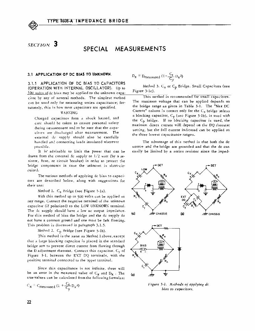
Method 1. Cs Bridge (see Figure 3-1a).
With this method up to 500 volts can be applied on any range. Connect the negative terminal of the unknown
capacitor (if polarized) to the LOW UNKNOWN terminal. The de supply should have a low ac output impedance. For this method of bias the bridge and the de supply do
not have a common ground and one must be left floating. This problem is discussed in paragraph 3.1. 5.
Method 2. Cp Bridge (~ee Figure 3-1b).
This method is the same as Method 1 above, except
that a large blocking capacitor is placed in the standard bridge arm to prevent direct current from flowing through the D adjustment rheostat. Connect this capacitor, Cy of Figure 3-1, between the EXT DQ terminals, with the positive terminal connected to the upper terminal.
Since this capacitance is not infinite, there will be an error in the measured value of Cx and Dx . The true values can be calculated from the following formulas:
c - c (1 +~o 2) x - measured c x y
22
Dx = Dmeasured (1- ~t Dx 2)
.Y
Method 3. Cs or Cp Bridge. Small Capacitors (see Figure 3-1c).
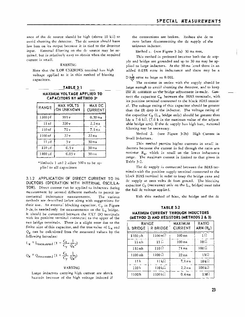
This method is recommended for small capacitors. The maximum voltage that can be applied depends on the bridge range as given in Table 3-1. The "Max DC Current" column is correct only for the Cs bridge unless a blocking capacitor, Cy (see Figure 3-lb), is used with
the Cp bridge. If no blocking capacitor is used, the maximum direct current will depend on the DQ rheostat
setting, but the full current indicated can be applied on the three lowest capacitance ranges.
The advantage of this method 1s that both the de source and the bridge are grounded and that the de can easily be limited by a series resistor since the .imped-
(a) CHASSIS
Figure 3-1. Methods of applying de bias to capacitors.
ance of the de source should be high (above 10 kO) to avoid shunting the detector. The de source should have low hum on its output because it is tied to the detector input. External filtering on the de source may be required, but is relatively easy to obtain when the required
current is small.
WARNING
Note that the LOW UNKNOWN terminal has high voltage applied to it in this method of biasing
capacitors.
TABLE 3-1
MAXIMUM VOLTAGE APPLIED TO CAPACITORS BY METHOD 3*
RANGE MAX VOLTS MAX DC
ON UNKNOWN CURRENT
1100 pf 393 v 0.39 rna
11 nf 220v 2.2ma
llO nf 7lv 7.1 rna
1100 nf 22v 22ma
11 j.1f 3v 30ma
110 j.1f 0.3 v 30ma
1100 j.1f 0.03 v 30ma
* Y.ethod s 1 and 2 allow '500 v to be applied to all capacitors
3.1.2 APPLICATION OF DIRECT CURRENT TO INDUCTORS (OPERATION WITH INTERNAL OSCILLATOR). Direct current can be applied to inductors during measurement by several different methods to permit increr..ental inductance measurements. The various methods are described below along with suggestions for their use. An external blocking capacitor, Cy in Figure 3-2a, is needed only for measurements on the Ls bridge. It should be connected between the EXT DQ terminals with its positive terminal connected to the upper of the two bridge terminals. There is a slight error due to the finite size of this capacitor, and the true value of Lx and
Qx can be calculated from the measured values by the following formulas:
Lx = Lmeasured ( 1 + Ct _!_2) Cy Qx
( + Ct 1 Qx = Qmeasured 1 C n+lQ )
y X
WARNING
Large inductors carrying high current are shock hazards because of the high voltage induced if
SPECIAL MEASUREMENTS
the connections are broken. Reduce the de to zero before disconnecting the de supply of the unknown inductor.
Method .i. (see Figure 3-2a) 30 rna max..
This method is preferred because both the de supply and bridge are grounded and up to 30 rna may be applied to large inductors. At the 30-ma level there is an added 0.03% error in inductance and there may be a
1 D tQ' error as large as 0.001.
The resistor in series with the supply should be large enough to avoid shunting the detector, and to keep the de constant as the bridge adjustment is made. Cel'lnect the capacitor Ce between the BIAS terminals, with its positive terminal connected to the black BIAS terminal. The voltage rating of this capacitor should be greater than the IR drop in the inductor. The voltage rating of
the capacitor Cy (Ls bridge only) should be greater than Ide x 7.6 k.O. (7.6 k is the maximum value of the adjustable bridge arm). If the de supply has high hum, external filtering may be necessary.
Method 2. (see Figure 3-2b) High Current in Small Inductors.
This method permits higher currents in small inductors because the current is fed through the ratio arm resistor Ra, which is small on the lower inductance range. The maximum current is limited to that given in Table 3-2.
The de supply is connected between the BIAS terminals with the positive supply terminal connected to the black BIAS terminal in order to keep the bridge case and de supply at zero volts de from ground. The blocking capacitor Cy (necessary only on the Ls bridge) must take the full de voltage applied.
With this method of bias, the bridge and the de
TABLE 3-2 MAXIMUM CURRENT THROUGH INDUCTORS
(METHOD 2) AND RESISTORS (METHODS 2 & 3)
RANGE MAXIMUM RATIO L BRIDGE R BRIDGE CURRENT ARM (Ra)
1100 f-Lh 1100 m.O 100ma 1.0
11 mh 11.0 100ma 10.0
110 mh 110.0 71ma 100.0
1100 mh 1100.0 22ma 1k.O
llh 11 k.O 7.1 rna 10 k.O
llOh 110 k.O 2.2ma 100 k.O
1100h 1100 k.O 0.4ma 1MD
23
~---T_YP_E_l_6_08_-A __ I_M_P_E_D_A_N_C_E __ B_R_ID_G_E_' ____________________________ _
supply do not have a common ground and one must be
left floating. This problem is further discussed in para
graph 3.1. 5.
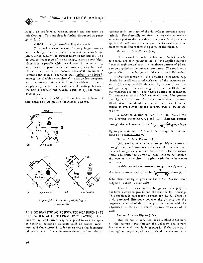
Method 3. Large Currents (Figure 3-2c).
This method must be used for very large currents and the bridge does not limit the amount of current applied, since none of the current flows in the bridge. The ac source impedance of the de supply must be very high, since it is in parallel with the unknown. An inductor, La, very large compared with the unknown, may be used. Often it is possible to resonate this shunt inductor to increase the source impedance still further. The imped-
ance of the blocking capacitor, Cf, must be low compared with the unknown since it is in series with it. If the de supply is grounded there wifl be a de voltage between the bridge chassis and ground, equal to Ide (de resist
ance of Lx).
The same grounding difficulties are present for this method as are present for Method 2 above.
DET
Figure 3-2. Methods of applying de to inductors.
3.1.3 DC BIAS FOR AC RESISTANCE MEASUREMENTS (OPERATION WITH INTERNAL OSCILLATOR). A de bias voltage and current may be applied to various types of nonlinear resistive elements such as diodes, varistors, and thermistors in order to measure the incremental resistance. For voltage-sensitive devices, the ac
24
resistance 1s the slope of the de voltage-current characteristic. For thermally sensitive devices the ac resistance is equal to the de value if the same total power is applied in both cases (as long as the thermal time constant is much longer than the period of the signal).
Method 1. (see Figure 3- 3a).
This method is preferred because the bridge and de source are both grounded and all the applied current flows through the unknown. A maximum current of 30 rna may be applied to the unknown resistors. The total voltage applied to the bridge should not exceed 400 volts.
The impedance of the blocKing capacitor, Cd, should be small compared with that of the unknown resistor (this may be difficult when Rx is small), and the voltage rating of Cd must be greater than the IR drop of the unknown resistor. The voltage rating of capacitor, Ce, connected to the BIAS terminals should be greater than Ide x 7.6 kD and the capacitance should be over 50 flf. A resistor should be placed in series with the de supply to avoid shunting the detector with a low ac Impedance.
A variation in this method is to short-circuit the
two blocking capacitors, Cd and Ce· Then the current
through the unknown will be Iinput (Ra ~a Rx), where
Ra is given in Table 3-2, and the voltage and current
Method 2. (see Figure 3-3b).
This method can be used to get higher currents through small unknown resistors, and the current limit for each range is given in Table 3-2. The maximum voltage is limited to 71 volts. Also, this method avoids the use of a capacitor in series with the unknown or ratio arm.
In this method the current through the unknown is
the total current multiplied by ( Rt ), where Rt is Ra + Rt
6667 ohms and Ra is given in Table 3-2. On the lower ranges this ratio is near unity.
Also, for this method the bridge and de supply do not have a common ground and one must be left floating. This problem is discussed in paragraph 3.1. 5. There is a de potential difference between the chassis and the negative terminal of the de supply that varies with the adjustment of the CGRL control up to a maximum of 37 volts.
Method 3. (see Figure 3-3c).
This method is very similar to Method 2 but here all the current flows through the unknown and a very low-impedance de supply is required. If the de supply has high ac output impedance, it should be shunted with

a large capacitor since it is 1n senes with the unknown resistor.
With this method the bridge and de supply do not have a common ground and one must be left floating. This problem is discussed in paragraph 3.1. 5. There will be a de potential between the chassis and negative terminal of the de supply, equal to approximatell' Ide Ra.
Method 4. (see Figure 3-3d).
With this method any amount of de may be supplied to the unknown resistor because none of the current flows through the bridge and the applied voltage is limited only by the voltage rating of the blocking ca-pacitor.
Here the de supply shunts the unknown, and it is necessary to use a series resistor or inductor with an impedance much larger than that of the unknown. Therefore, this method is limited to relatively small resistors. Also, for this method there is a grounding problem since the bridge and the de supply do not have a common ground. See paragraph 3.1.5. There will be a de potential between the chassis and negative terminal of the de supply, equal to approximately Ide Rx.
DET
(d) CHASSIS
Figure 3-3. Methods of applying de to resistors for ac resistance
measurements.
SPECIAL MEASUREMENTS
3.1.4 APPLICATION OF DC BIAS WITH EXTERNAL AC GENERATOR. When an external generator is used, the grounding problem (see paragraph 3.1. 5) becomes even more serious since the internal detector is not selective in the EXT AC position and the hum pickup is unattenuated. In many cases it will be necessary to use an external selective detector, such as the Type 1232-A Tuned Amplifier and Null Detector. In some cases the induced hum may overload the internal detector, causing erroneous readings, in which case the external detector should be connected between the LOW UNKNOWN terminal and the bridge panel rather than to the DET OUT terminals. In extreme cases, the bridge may be discon-nected from the power line, thus removing all internal source of hum. This has the disadvantage of turning off all the indicator lights.
For those biasing methods where the de supply and the bridge have a common ground, the external ac supply should be connected to the EXT GEN terminals which have the same common ground. With those methods that do not have a common ground between the bridge and de supply, it is generally best to ground the external de and ac supplies at the same point, as shown i.n Figures 3-4a and 3-4b, and ungroul'ld the bridge. A resistor should be put in parallel with the ac generator to provide a de path. When the bridge is floating and an external detector is used, this detector is also floating and should be battery operated (as is the Type 1232-A) to avo1
3. 1.5 GROUNDING PROBLEMS WITH DC BIAS. For those biasing methods described above that do not have a ground in common with the bridge chassis, it is necessary to float (unground) either the de supply or the bridge. This results in two difficulties. First, there is
CAPACITANCE BRIDGE (METHOD 2)
INDUCTANCE BRIDGE (METHOO 2)
Figure 3-4. Connections of external ac and de supplies.
25

~---T_Y_P_E_1_60_8_-A __ IM_P __ E_D_A_N_C_E __ B_R_ID_G_E_1
____________________________ __
capacitance from the floating bridge or power supply to ground, which can cause an error if it is placed across a bridge arm. Second, there is generally capacitive coupling between the floating bridge de supply and the ac
line, which causes hum pickup in the detector, resulting in a residual deflection.
If the de supply is self-powered, it should be left
floating and spaced a way from any ground, and the bridge should be grounded. If the de supply is lineoperated, it will probably have more capacitance to ground and to the power line than has the bridge, and
therefore the supply should be grounded and the bridge tmgroundc d. To disconnect the 'or idge from ground, open the link between the rear terminal labeled 3RD WIRE GROUND and the adjacent CHASSIS terminal. The 3RD WIRE GROUND terminal will be grounded if a three-wire power cord is used and should be grounded externally if a two-wire cord is used.
When the bridge is floating, there is approximately 300 pf between the case and the 3RD WIRE GROUND internally. External capacitance from the case to ground will increase this total value somewhat. If the BIAS terminals or the UNKNOWN terminal not marked LOW is grounded, this capacitance will be placed across the standard capacitor for capacitance measurements, across the fixed standard resistor, R, for conductance measure
ments, and across the CGRL adjustment for resistance and inductance measurements. The error due to this
capacitance can be computed from the equations of Table 2-6. For 300 pf, the main errors are a 0. 2% error in capacitance measurements, a Q error of- 0.013 for Gp measurements, a maximum Q error of + 0.013 for Rs measur.emenJs (dependent upon the CGRL counter set-
. ) d 0 ~ 0 ung an a maxrmum D 'CJ' error of - 0.013 for mductance
measurements (dependent upon the CGRL control setting).
If the bridge is grounded at the LOW UNKNOWN terminal, this capacitance is placed across the detector where it causes no error.
The residual deflection caused by hum pickup can seriously limit the accuracy obtainable, particularly if the detector is not selective as it is when an external geqerator is used (refer to paragraph 3.1. 4). The hum pickup will be about the same when either UNKNOWN terminal or the BIAS terminals are grounded when low impedances are measured, but can be much worse when high impedances are measured and the LOW UNKNOWN terminal is grounded. Earphones may be helpful in detecting the null of the fundamental in the presence of hum. In extreme cases, the bridge can be disconnected from the power line and a battery-operated selective detector, such as the Type 1232-A Tuned Amplifier and Null Detector, can be used to avoid all internal hum pickup.
26
3.2 MEASUREMENTS ON SHIELDED THREE-TER-MINAL COMPONENTS.
When the unknown component is shielded, and the shield is not tied to either unknown terminal, a threeterminal component is formed (see Figure 3-5). The impedance, Z, of the component itself is the direct imped
ance of the three-terminal system. To measure the direct impedance, connect the shield (third terminal) to the bridge chassis, using any grounded terminal or a ground lug held by the screw directly below the UNKNOWN ter
minals. Connect the UNKNOWN terminal with the larger capacitance to ground to the LOW UNKNOWN terminal, because capacitance from the other UNKNOWN terminal to ground may cause an error if it is large enough. See Table 2-6 and paragraph 2.4.5.1.
Often the shield of an inductor is not connected to either terminal. When the inductance and frequency are so low that stray capacitance across the inductor causes negligible error, the shield should be connected to the LOW UNKNOWN terminal. When the inductance (or frequency) is high, the effective inductance is increased because of the shunting capacitance. The error is + 100 ( u.:2L xCx)% (refer to paragraph 2.4. 2. 2). To avoid an inductance error, the shield may be tied to the panel of the bridge. The inductor terminal that has the large capacitance to the shield should be tied to the LOW UNKNOWN terminal. A Q error results from the capacitance from the other UNKNOWN terminal to the shield (Cb in Figure 2- 3) but a better measurement of Lx is possible (this connection does not affect the winding capacitance itself).
3.3 REMOTE MEASUREMENTS. Because of the small effect of capacitance to
ground, particularly for capacitance measurements (refer
to paragraph 2.4.5.1), the unknown may be placed some distance from the bridge. At least one of the connecting leads should be shielded to avoid the errors due to capacitance between the leads shunting the unknown. The shielded lead should be connected to the LOW UNKNOWN terminal and its shield tied to the bridge chassis. The other lead may also be shielded, but this will increase the capacitance to ground, causing an error (see Table 2-6 and paragraph 2.4.5.1). When low-impedance meas-
Pigure 3-5. Shielded three-terminal
impedance.

urements are made, the effects of lead resistance and inductance should be considered (see Table 2-5).
3.4 USE OF TYPE 1650-Pl TEST JIG.
3.4.1 GENERAL. The Type 1650-P1 Test Jig provides a means of making quick connections to the bridge with a pair of conveniently located clip terminals. When the Type 1650-A is set up for limit measurements (refer to paragraph 3.6), the combination facilitates the rapid sorting of electrical components.
The jig is also useful for measurements on small capacitors because of its small zero capacitance and because the unknown component is positioned and shielded to make repeatable measurements possible.
3.4.2 INSTALLATION. The test jig is connected to the bridge UNKNOWN terminals by means of the shielded Type 27 4 Connector attached to the jig. A three-terminal connection is necessary. The third connection is made by means of the screw, located directly below the UNKNOWN terminals, and the lug on the shield of the connector. This screw makes the ground connection to the jig and also holds the connector in place.
The leads of the test jig can be routed through cable clamps secured by the fluted panel screws so that the jig can be located directly in front of the bridge without interference from the leads.
3.4.3 RESIDUAL IMPEDANCES OF TEST JIG. The residual resistance of the leads is about 80 milliohms (total) and the inductance is about 2 ph. The zero ea pacitance, when the leads are connected to the bridge, is approximately 0.2 pf. The shielded leads cause a capacitance to ground of about 100 pf each. Corrections may be necessary for the residual resi~tance and inductance when measurements are made on low impedances (see Table 2-5). The capacitances to ground cause an error of 0.07% for capacitance measurements, but can
1 cause a D (Q) error up to about 0.004 for inductance
measurements (see Table 2-6).
3.5 MEASUREMENTS ON GROUNDED COMPONENTS. If the component to be measured is grounded, the
cabinet of the Type 1608-A must be disconnected from
ground. To do this, open the !.ink between the rear ter
minal labeled 3RD WIRE GROUND and the adjacent ter
minal tied to the chassis. The 3RD WIRE GROUND
should be grounded externally if an ungrounded, two-wire
power cord is used (refer to paragraph 2.1. 2).
If the LOW UNKNOWN terminal is grounded there is no error due to the capacitance of the bridge to ground, but there is a residual meter deflection due to internal hum pickup in the bridge as well as external hum pickup to the bridge chassis which can usually be removed by grounding of nearby equipment. This hum pickup can become very large when high-impedance components are measured.
~PECIAL MEASUREMENTS
There is less hum pickup in the measurement of high-impedance components if the other (unlabeled) UNKNOWN terminal is grounded. However, the internal capacitance of the bridge chassis to ground (approximately 300 pf), plus any external capacitan.ce from the chassis to ground, will shunt one arm of the bridge, causing an error given in Table 2-6.
Even when the bridge is floating, the bridge chassis can be used as a guard terminal for three-terminal or remote measurements.
3.6 LIMIT TESTING. The Type 1608-A can be set up to provide a go-no
go indication useful fer eempenent setting The panel meter is used as the indicator. The procedure is as follows:
a. Balance the bridge with one of the components to be measured (preferably one within tolerance).
b. Offset the CGRL setting by the desired tolerance, if the tolerance is symmetrical, or by one half of the total allowable spread if unsymmetrical.
c. A~just the DET SENS control for five-divi-sion meter deflection.
d. Set the CGRL dial to the center value (the nominal value if the tolerance is symmetrical).
e. Connect each component to the bridge (or Type 1650-P 1 Test Jig). If the meter deflection is less than five divisions, the component is within limits.
When the unknown has a tolerance greater than ± 10%, the limits may be ia errer by mart> than 1% if the above method is used. A sure method is to set the CGRL dial so that unknown components at both limits give the same deflection.
3.7 MEASURING RESONANT FREQUENCY AND RESONANT IMPEDANCE OF TUNED CIRCUITS.
The resonant frequency of a series or parallel tuned circuit can be found with the use of an external vari
able-frequency oscillator. Either the Gp or Rs bridge may be used (depending upon the desired quantity). Connect
the external generator to the EXT GEN terminals and set the function switch to EXT AC. Set the Q balance adjustment to zero, and null the bridge using the con· ceD;tric CGRL controls and the frequency adjustment on the oscillator.
~t null the bridge reads th~ effective Rs or Gp of the tuned circuit at that frequency where the tuned circuit is resistive. The resonant frequency is indicated by the variable-frequency oscillator. The accuracy of the Rs or Gp reading depends on the test frequency (refer to paragraph 2. 5. 5) and the accuracy of the resonant frequency depends on the Q of the tuned circuit, and is limited to the frequency change that would give a measurable change in the bridge Q adjustment ( ±0.0005
f 1 kc' above 1 kc).
27

~--~T_Y_P_E_16_0_8-_A_I_M_P_E_D_A_N_C_E __ B_R_I_D_G_E __________________ ~----------
3.8 MEASUREMENT OF Rp·
To measure the parallel resistance of capacitive resistors directly (rather than measuring Gp and inverting) place an external capacitor, Cn, across Rn
of the 1\, bridge (see Figure l-2). Set the internal Q adjustment, Ct, for a zero reading and balance the bridge with Rn and the external capacitor. At balance, the main
SECTION 4
PRINCIPLES OF
4.1 BRIDGE CIRCUITS.
Figure l-2 shows the six bridge circuits used in the Type 1608-A Impedance Bridge as well as the balance equations. These six bridges completely cover the passive half of the complex impedance plane as shown in Figure 4-1. There is considerable overlap between the . .
urement of series or parallel C or L over a wide range. Ls and Cp can each be measured over a full 90 degrees. The D coverage extends down to 0.02 (Q to 50), and at D's below 0.02 Lp = Ls and Cs = Cp to 0.04%, and at high D's or low Q's, the unknown can be measured as a resistance or conductance and Ls and Cp can be calculated from R or G and Q. Both ac and de measurements can be made on the R and G bridges.
The coaxial CGRL balancing controls consist of a 114-position detented switch and a continuously adjustable vernier, wire-wound rheostat. The switch introduces in the variable bridge arm fixed steps of resistance proportional to the first three digits of the indicating counrer that it drives. This adjustment is called a "centade," because it is similar to a decade-resistance unit but with approximately 100 positions. It uses precision wire-wound resistors (details of its operation are discussed in paragraph 4. 4). The vernier sets the last" two digits of the counter and adds resistance proportional to this reading in series with the resistance of the centade.
The ratio-arm resistors, which range from 1 ohm to 1 megohm, are all General Radio precision wire-wound resistors. The two ganged DQ adjustments are wirewound rheostats with a 40-db logarithmic range.
28
readout indicates Rp and the capacitance across the unkno'Ml is
To evaluate Rn multiply the indication of the main readout by 2/3 (neglect the decimal point).
OPERATION
The standard capacitor is specially constructed for low temperature coefficient. Most of its capacitance Is that of a General Radio silvered-mica unit, which has
""" 0=0.02
Figure 4·1. DQ coverage chart.

a positive temperature coefficient of approximately 35 ppm. A small, stabilized, polystyrene capacitor is in parallel with the mica unit to reduce the over-all temperature coefficient.
4.2 BRIDGE SOURCES AND DETECTORS. There are three de sources of approximately 3.5,
35 and 350 volts open-circuit that are connecte::l to the
bridge for de resistance and conductance measurements
according to the scl.edule of Table 2-1. Resistors in series with these sour.ces limit the power supplied to the bridge to less than 1/2 watt to avoid damaging the internal bridge resistors or the unknown
The de detector is a panel meter, with a sensitiVity of 1 ,Ua/mm near zero and a shaped characteristic to facilitate balancing. Its resistance is approximately 500 ohms. A more sensitive null indicator can be connected if desired, through connectors qn the rear panel (refer to paragraph 2. 3.4).
The ac generator is a 1-kc, two-stage, transistor RC oscillator. This drives a 3-to-1-stepdown shielded bridge transformer, with a maximum output of approximately I volt behind. 50 ohms. The GEN LEV control adjusts the voltage to the primary of the transformer.
The ac detector is a high-gain transistor amplifier with a twin-T in a feedback loop for selectivity at 1 kc. The DET SENS control on the input adjusts the gain. The range switch causes the gain to be increased on the two extreme bridge ranges, and a eempressiea cir cuit is used to reduce the necessity for constant readjustment of the DET SENS control during balance. This amplifier drives the pane I meter and has an auxiliary DET OUT connection.
In the EXT DC position of the function switch, the EXT GEN terminals are connected across the vertical diagonal of the bridge (see Figure 1-3) (with no series resistor), and the internal de detector is in place: When EXT AC is used, the EXT GEN terminals· are connected directly to the bridge transformer (see Figure 1-3) and the twin-T is removed from the detector to give it a flat frequency characteristic.
When other plug-in frequency modules replace the 1-kc module supplied, the selective circuits for the oscillator and detector are changed to produce the desired signal frequency and to provide selective amplification at that frelluency (refer to paragraph 2.4.4).
4.3 BRIDGE SWITCHING. The FULL-SCALE RANGE switch (Sl) changes
the ratio-arm resistor of the bridge. Two separate rotors are used so that a clockwise rotation will increase the size of the unit for all six bridges. Both ends of the resistors are switched out, and the unused resistors are grounded to reduce stray capacitance. The range switch
also positions the decimal point on the main readout, de-
1 PRINCIPLES OF OPERAT!ON
termines which de supply wi!l be used for de G or R
measurements and whe~e the supply and meter will be connected to the bridge, and increases the ac gain on the extreme bridge ranges.
The BRIDGE SELECTOR switch (S2) switches the internal bridge components to form the six bridges of Figure 1-2. It also connects the appropriate set of rotors for the range switch, determir.es which type of unit is Illuminated above the main readout, indicates the correct D or Q scale or type of resistance Q, and permits de to be applied to the b::idge only when it is in the G or R positions.
The function switch (S3) connects the appropriate generator and detector for internal and external ac and de measurements. In the EXT DC position the EXT GEN terminals are connected directly to the bridge, and in the EXT AC position they are connected directly to the primary of the bridge transformer.
All switches used in the bridge have solid sih er contacts, and double contacts are used on the range switch for low contact resistance.
4.4 CENTADE OPERATION. The adJustment for the first three digits of the
counter used as the CGRL readout places in the bridge circuit 114 precise steps of resistance. These steps
increase or decrease continuously with no discontinuity in the switching, other than the increase or decrease from one fixed value to the other, in order to avoid Sllddea aridge llRaalaaces that WQillG mgmentarily de-fleet the panel meter. A binary scheme, using only
seven resistors, could be switched to give 128 fixed
values, but there would be many places over the range where two switching operations would have to occur
at exactly the same moment to avoid a large transient. Or, 114 precision wire-wound resistors could be connected in series on a simple selector switch with a shorting rotor (as in a decade box) to give the desired operation, but would be quite expensive. To effect a 114-position decade-type switch (which we call a "centade") using fewer resistors, a scheme using three rotor contacts is used.
The operation of the centade is best explained by an examination of Figure 4-2. Briefly, fixed values in between the values of the series-resistor chain are obtained first by the shunting of one s~ries resistor with two resistors that will reduce it to 1/3 of its value. In the next step, one shunting resistor is removed, increasing the resistance to 2/3. In the third step, the series resistor is unshunted giving its full value, and the shunting resistors are moved into position to shunt the next series resistor on subsequent steps.
With this scheme, the number of series resistors is reduced to one third of 114 and two resistors are added to the rotor. This idea could be extended to reduce the number of resistors even further, but the number of
29
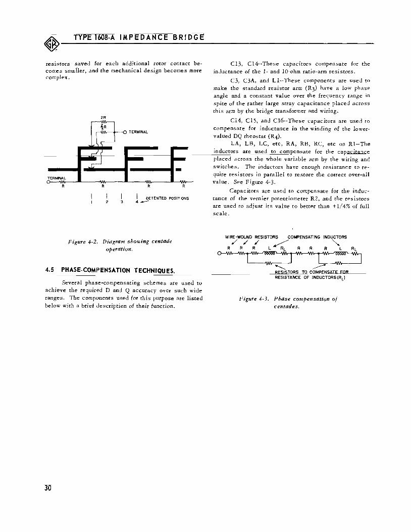
~---T_YP_E __ l6_08_-A __ I_M_P_E_D_A_N_C_E __ B_R_ID_G_E ________________________________ _
resistors saved for each additional rotor contact becomes smailer, and the mechanical design becomes more complex.
TERMINAL
R
2R
R
I 2 3
R R
DETENTED POSITIONS 4---
Figure 4-2. Diagram showing centade operation.
4.5 PHASE-COMPENSATION TECHNIQUES.
Several phase-compensating schemes are used to
achieve the required D and Q accuracy over such wide ranges. The components used for this purpose are listed
below with a brief description of their function.
Cl3, Cl4--These capacitors compensate for the inductance of the 1- and 10-ohm ratio-arm resistors.
C3, C3A, and Ll--These components are used to make the standard resistor arm (R3) have a low phase angle and a constant value over the frequency range in spite of the rather large stray capacitance placed across this arm by the bridge transformer and wiring.
Cl4, Cl5, and Cl6--These capacitors are used to
compensate for inductance in the winding of the lowervalued DQ rheostat (R4).
LA, LB, LC, etc, RA, RB, RC, etc on Rl--The inductors are used to com ensate for the ca acit ::1
placed across the whole variable arm by the wiring and
switches. The inductors have enough resistance to require resistors in parallel to restore the correct over-all value. See Figure 4-3.
Capacitors are used to compensate for the inductance of the vernier potentiometer R2, and the resistors are used to adjust its value to better than ± 1/4% of full scale.
WIRE-WOUND RESISTORS COMPENSATING INDUCTORS
R / R/ ~ l < R R R "'L
_____., RESISTORS TO COMPENSATE FOR RESISTANCE OF INDUCTORS(RL)
Figure 4-3. Phase compensation of centades.

SECTION 5 SERVICE AND
5.1 GENERAL. The two-year warranty given with every General
Radio instrument attests the quality of materials and
workmanship in our products. When difficulties do occur, our service engineers will assist in any way possible.
In case of difficulties that cannot ue eliminated by the use of these service instructions, please write or phone our Service Department, giving full information of the trouble and of steps taken to remedy it. Be sure to mention the serial and type numbers of the instrument.
Before returning an instrument to General Radio for service, please write to our Service Department or nearest district office (see back cover), requesting a Returned Material Tag. Use of this tag will insure proper handling and identification. For instruments not covered by the warranty, a purchase order should be forwarded to avoid unnecessary delay.
5.2 CALIBRATION CHECKS.
5.2.1 FIXED BRIDGE COMPONENTS. A calibration check of the fixed-bridge components in the Type 1608-A
1 SERVICE AND MAINTENANCE
MAINTENANCE
Impedance Bridge can be made by the series of measurements listed below.
The accuracy of this calibration check depends on the accuracy of the internal standards used. A General Radio Type 1409-T Standard Capacitor is recommended as a capacitance standard. 'fhis capacitor is calibrated
to ±0.03%. Type 500 Resistors are recommended as the resistance standards. Their accuracy is 0.05% (except for the 1-ohm unit, whose accuracy is 0.15%). More accurate resistors should be used if available, or Type 500 Resistors can be measured to greater accuracy if a suitable bridge is available.
a. Check of Rt (Standard Resistor). Measure a 10-kD resistor on both the Rs bridge (11-kD range) and the G bridge (110-flU range). The average of these t"\\U r!adings, neglecting decimal points, should be 10000, and the difference from this value indicates the error in Rt. (Actually,, it is the difference between the centade, Rn, and Rt.) (If this error is greater than 0.05% (that is, if the average of the two readings is less than 9995 or more than 10005), adjust Rt with the potentia-meter, Rl6 (see Figure 5-4).)
TABLE 5-1
EXT STD
ID
IOD
IOOD
lk
1k
lOk
lOOk
IMD
RATIO ARM CHECKING PROCEDURE
(Refer to paragraph 5.2.1 .)
BRIDGE RANGE Ra RESISTOR
Rs llOOMD R7
Rs llD R8*
Rs llOD R9*
Rs 11000 RIO*
GP uoo flu Rl4
Gp llOJ.LU R15
GP u flu Rll
GP llOOnU R13
+ERROR MEANS Ra
too small
too small
too small
too small
too large
too large
too large
too large
*Actually, the ratio arms for these ranges are the sum of several resistors, but if the previous measurement is correct, the indicated resistor is the component in error.
31

~---T_Y_P_E_16_0_8-_A_I_M_P_E_D_A_N_C_E __ B_R_I_D_G_E ____________________________ __
obtain the correct value if it is too high. If Rt is too
low, place small resistors in series with Rr; an easy
way of doing this is to connect them to L1 with short
leads.
b. Ratio Arms (Ra). If Rt is of the correct value, the ratio-arm resistors can be checked by the
series of measurements given in Table 5-l. Note that the same set of ratio arms is used on all bridges except that there are two 1-k resistors (see Table 2-7). The C
and G bridges use R14 as a 1-k ratio arm and the L and
R bridges use the series sum of R7 + RS + R9 + RIO. The ratio arms may be double-checked by measurement of each external standard (when possible) on both the Rs
and Gp bridges.
c. Check of Ct (Standard Capacitor). To check the standard capacitor, Ct, measure any capacitor of known value. For best resolution, choose the value of the capacitor and range of the bridge for a full-scale indication. Before measuring the capacitor, check the ratioarm resistor for the range used (refer to Table 2-7 for ratio-arm values). If the bridge indication is in error by more than 0.05%, adjust Ctwith the variable capacitor, C17 (see Figure 5-4), or, if necessary, change the values of the radding capacitors.
Note that if a General Radio Type 1401 Air Capacitor is used for accuracy checks on the lowest capacitance range, the bridge indication will be about 0.3 pf high even after th€ f€siclual zers capacitance is sub-tracted from the measured value. This discrepancy occurs because the Type 1401 is calibrated with a grounded measurement, whereas the Type 1608 Bridge measures the capacitor with neither terminal grounded.
5.2.2 CHECK OF CENT ADE ACCURACY. It is not nec
essary to check the total value of the centade, since if
it is slightly in error, a correction of Rt and Ct will give the correct bridge readings (see above). However,
the centade must have good linearity. It can be checked
over its range by measurement of a decade resistor on the bridge as it is adjusted over the range. A General
Radio Type 1432-K is recommended, and this should be
adjusted in 10-ohm steps to check each step of the centade. Actually, it is necessary to check only those cent
ade positions that are divisible by three once the first
two steps have been checked (refer to paragraph 4.4).
5.2.3 CHECK OF CGRL VERNIER ADJUSTMENT (R2). The vernier rheostat adjustment can be checked by meas
urement of a 1-k decade resistor (Type 1432-K) on the
110- kD Rs bridge range. The shaft position of this potentiometer should be set to give a correct reading at 1 (10 ohms on the Type 1432-K), and the padding resistors should be adjusted for best accuracy over the rest of the range.
32
5.2.4 DQ CHECKS. D and Q scale checks can be made by calculation of D and Q of series or parallel RC com
binations of precision components. Checking the two
capacitance bridges is much easier than checking the inductance bridges, and checks on both are not necessary since the DQ scales depend upon the same compo
nents for both bridges (see Figure 1-2). Likewise, it is
easier to check the Gp bridge than the Rs bridge.
The fixed phase-shift error (±0. 0005) can be checked •.Jn the C bridge by measurement of capacitors with low,
known D values. The D error on the lowest C range depends somewhat on the position of rhe 1-M ratio arm
(R13). The fixed Q error on th~ Rs and Gp bridges can
be set by adjustment of C3 (just below the standard capacitor) to give a zero Q reading when a 1-k composition or film resistor is measured.
5.3 ADJUSTMENTS.
5.3.1 OSCILLATOR OUTPUT CONTROL (R529). This
control, on the rear of the printed wiring board at the top
of the instrument, controls the maximum output level of the internal RC oscillator. It should be set to give an
unclipped output at anchor terminals 32 and 31 when the GEN LEV control is fully off (counterclockwise).
5.3.2 CEI'-ITADE ADJUSTME~HS. Thc mechanical ad-justments of the centade should not be necessary unless
the centade assembly has been taken apart. If adjust
ment i~ necessary, it should be done carefully and in the correct sequence.
First, adjust the posrtion of the detent block so that the digits of the counter readout are centered in the window. To do this, siightly loosen the hex-head nuts
on the rear of the subpanel and rotate the detent block.
Next, connect a component of known value to the bridge and set the FULL SCALE RANGE switch and CGRL control to the correct value. Then balance the bridge by positioning the rotor of the centade. This setting should be accurately made since the centade should change
value halfway between the detented steps. Tighten the rotor set screws. It is best to check the centade adjust
ments at several points of its range. Finally, loosen the centade knob (the larger knob)
and set it so that a zero reading appears when the knob
hits the stop, which is on the dress panel under the knob.
The pressure for the centade detent is adjusted by
the screw on the detent block directly behind the front
panel. The setting of this pressure is a matter of personal preference. Too tight an adjustment will make the control difficult to rotate, and too· loose an adjustment will not give the necessary detent action to ensure that the centade rests on a detented position.

5.3.3 ADJUSTME~T OF CGRL VERNIER CONTROL. The procedure for setting the vernier CGRL control with respect w the counter reading is given in paragraph 5. 2. 3 above. The stop for this control, mounted on the front of the plate holding die vernier rheostat (see Figure 5 ),should be set to give a zero reading when the potentiometer is
fully counterclockwise. To do this, slightly loosen the hex-head screws and push the detent block in or out as necessary.
5.3.4 DQ RHEOSTAT ADJUSTMENT. The ganged DQ rheostats (R4 and R5) should be set to gi'le the best o'ler-all tracking with the DQ dial, as determined by measurement of RC networks with known D values (see paragraph 5. 2.4). The dial should be positioned to give the best tracking with the inner rheostat (R4, LOW D). Then the rotor of the rear rheostat (R5, HIGH D) should be set on the shaft to give the best tracking with the dial.
5..4 REPLACING INDICATOR LAMPS.
The indicator lamps are operated well below their rated voltage and should last for many years. If they do require replacement, the pilot light and the two lamps labeled INDUCTIVE and CAPACITIVE can easily be replaced after their lenses are unscrewed. To replace the other lamps, it is necessary- to rernove the dress ranel.
ISERVICE AND MAINTENANCE
To do this, remove the eight panel screws at the edges, the two screws directly below the meter, and all knobs
except the DQ knob.
In order to replace the lamps under the DQ dial, the dial must be removed. Before removing the dial, make a note of its setting so that it can be replaced accurately. The unit dial mu~;t be removed to replace the unit indicating lamps and should be replaced in the same position. To replace the lamps held in place by insulating washers, it is easier to unsolder the connection on the pin coming through the washer. Be careful not to let solder or rosin rwt down this pin and ptevent its ftee movement in the washer.
All lamps are GE Type 327 miniature lamps and are a\lail:o.ble in most hardware or hobby stores. If unavailable locally, they are available from General Radio Company (our Type 2LAP-7).
A schematic diagram o( the lamp circuits is shown in Figure 5-12.
5.5 TROUBLE-SHOOTING SUGGESTIONS.
5.5.1 BRIDGE PROPER. a. Bridge Error. Refer to paragraph 5.2 for a cali
bration procedure that will locate any bridge component that is in error.
TABLE 5-2
DC VOLTAGES ON OSCILLATOR-DETECTOR-AMPLIFIER CIRCUIT BOARD CONTROL SETTINGS: DET SENS: fully clockwise
GEN LEVEL: fully clockwise Power: AC INT BRIDGE SELECTOR: Rs
TRANSISTOR PIN DC VOLTS
TRANSISTOR (TYPE) (TYPE)
E 11.4 Q552 Q525 B 11.2 (2N445A) (2N520A) c 6.4
E 10.6 Q553 Q526 (2N520A) B 11.0
(2N 1415) c 4.7
E 0.57 Q554
Q550 (2N445A) B 0.61
(TRl) c 1.62 Q555
E 1.95 (2N520) Q551
B 1.62 OSC OUTPUT (2N445A) c 3.77 DC .L."l"PUT
RANGE: 1100 mO CGRL: maximum UNKNOWN terminals open
PIN DC VOLTS
E 1.82
B 1.67 c 4.95
E 2.88
B 3.77 c 1.68
E 7.0 B 6.3 c 7.9
E 8.1 B 7.9 c 6.6
32 2.5 vac 42 14.0 vdc
33
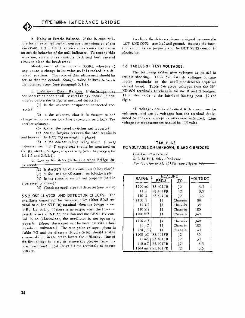
~---T_Y_P_E_l_60_B-_A __ IM_P_E_D_A_N_C_E __ B_R_I_D_G_E_' ------------------------------
b. Noisy or Erratic Balance. If the instrument is idle for an extended period, surface contamination of the wire-wound DQ or CGRL vernier adjustments may cause an erratic behavior of the null indicator. To remedy this situation, rotate these controls back and forth several times to clean the brush track.
Misalignment of the centade (CGRL adjustment) may cause a change in its value as it is rocked in a detented position. The rotor of this adjustment should be set so that the centade changes value halfway between the detented steps (see paragraph 5.3.2).
c. Inability to Obtain Balance. If the bridge does not seem to balance at all, several things should be considered before the bridge is assumed defective.
(1) Is the unknown component connected cor-reedy?
(2) Is the unknown what it is thought to be? (Large inductors can look like capacitors at 1 kc.) Try another unknown.
(3) Are all the panel switches set properly? ( 4) Are the jumpers between the BIAS terminals
and between the EXT DQ terminals in place? (5) Is the correct bridge being used? (Low Q
inductors and high D capacitors should be measured on the Rs and Gp bridges, respectively (refer to paragraphs 2.4.1.1 and 2. 4. 2. 1).
d. Low or No Meter Deflection when Bridge Un-
balanced. (1) Is theGEN LEVEL control on (clockwise)? (2) Is the DET SENS control on (clockwise)? (3) Is the function switch set properly (and in
a detented position)? (4) Check the oscillator and detector (see below).
5.5.2 OSCILLATOR AND DETECTOR CHECKS. The oscillator output can be measured from either BIAS terminal to either EXT DQ terminal when the bridge is set to Rs, Ls, or Lp. If there is no output when the function
switch is in the INT AC position and the GEN LEV control is on (clockwise), the oscillator is not operating properly. (Note: the output will be very low with a lowimpedance unknown.) The test point voltages given in Table 5-2 and the diagram (Figure 5-16) should enable anyone skilled in the art to locate the difficulty. One of the first things is to try to remove the plug-in frequency board and bend up (slightly) all the terminals to ensure
contact.
34
To check the detector, insert a signal between the LOW UNKNOWN terminal and ground. Be sure the function switch is set properly and the DET SENS control is clockwise.
5.6 TABLES OF TEST VOLTAGES.
The following tables give voltages as an aid in trouble-shooting. Table 5-2 lists de voltages at transistor terminals on the oscillator-detector-amplifier etched board. Table 5-3 gives voltages from the UNKNOWN terminals to chassis for the R and G bridges ] 1 in this table is the left-hand binding post, J 2 the right.
All voltages are as measured with a vacuum-tube voltmeter, and are de voltages from the terminal designated to chassis, except as otherwise indicated. Line voltage for measurements should be 115 volts.
TABLE 5-3 DC VOLTAGES ON UNKNOWN, RAND G BRIDGES
Centade at maximum
CF!N LEVEL fully clockrl'ise
Fgr /gcatifm ef S3, 401 FR. see Figm e 5-1.
RANGE MEASURE VOLTS DC FROM ..IQ_
1100 mD S3,401FR ]2 3.5 11 D S3,401FR ]2 3.5
110 D S3,401FR ]2 3.5 1100.0 ]1 Chassis 30
11 kD J1 Chassis 35 llOkD ]1 Chassis 180
1100 kD Jl Chassis 340
1100 nU Jl Chassis 340 11 f-llJ ]1 Chassis 180
110 f-llJ ]1 Chassis 40 1100 f-llJ S3,401FR ]2 35
11 mU S3,401FR ]2 30 110m7J S3,401FR ]2 3.5
1100 mU S3,401FR ]2 3.5
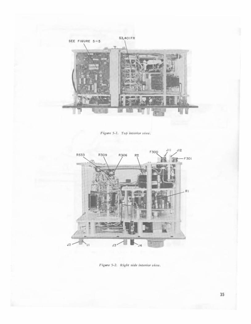
S3,401 FR
FigUT~ 5·1. Top interior t·i~u .
Fig'"~ 5·2. Right sid~ int~rior vi~u-.
35
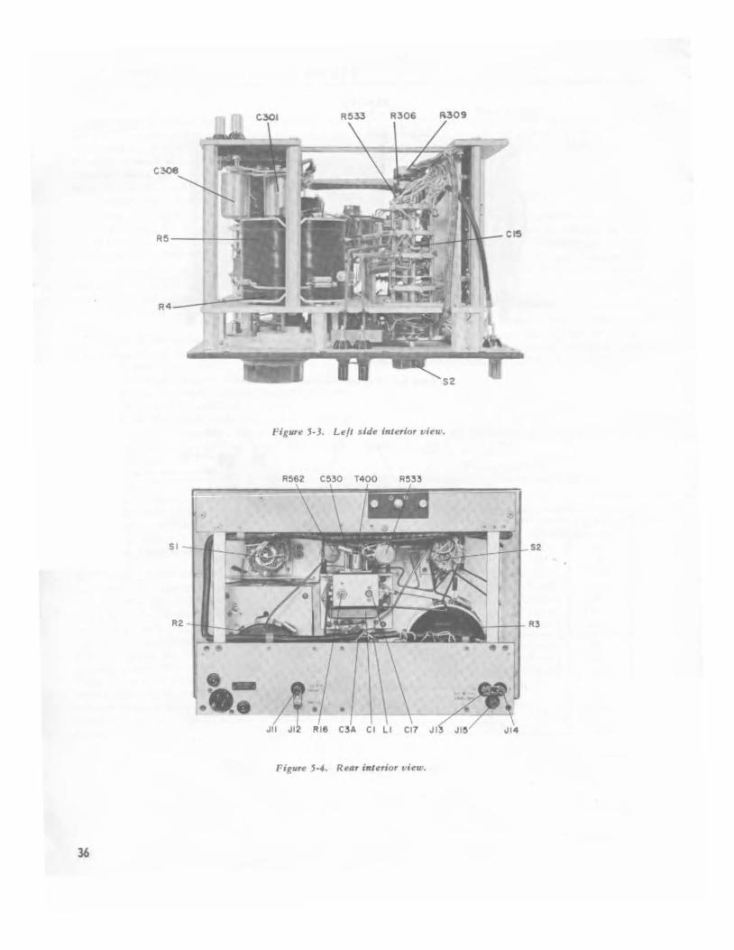
,..·;gurf! 5-3. Lf!/1 :sidf! inlf!rlor vi~w.
36

,
Figure 5·5. F. lcbed board la}oul.
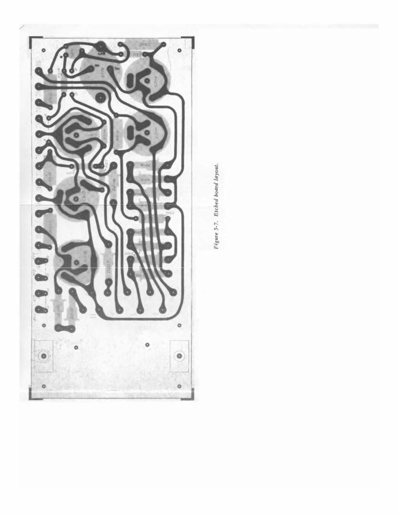
/
0 0
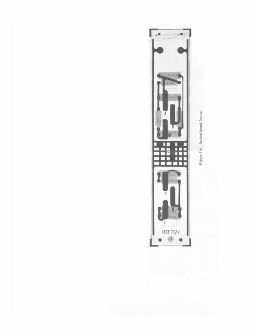
I~
I f
1608·73/ 2
L· ~ .

Lp HIGH Q, 1- oo
PARALLEL INOI/CTANCE
OET S3,204F
204F,R S2 vT
2'}jF.R
SIO!fR S2
307"F,R
RO
CENTAOE 0-7".5K.!J
RN
BR
VERNIER 0-71.2.!J
Lp = RNRACr
Rx I Qx"--=---
(;)Lx (;)CTRT
Gp
(CAP Q, 0-1.2)
PARALLEL CONDI/CTANCE
215F,R ETC
:;~1,; RA S~06F,R RATIO ARM
203F,R
cT o-.0298pF
RN Gx = RA Rr
RI3,1M.!J
S3
CCW VERNIER o.-71.2.!J
Ox= (;)Cx = (;)CTRT Gx
RA RATIO ARM
"DO"RT
Figure 5-B. Simplified scpematic diagram showing bridge circuits.
38
3/0F,R S2
'Vo"
OET
OET
~s fLOWO, 0-IJ
SERIES CAPACITANCE
S3,204F
WH 2/0F,R S2
20/F,R
0 Jl LOW
BL
IWF.~ ~ Sl
2~~~~ RATIO ARM
lii3,1M./2
:g~~~ Sl
413/iR 414F,R
S2,103R Y"E ~~~~-;oo.~oo~~.-~~-~~~~306F,R
RN Cx = RA CT
4/0R 40/R S2
CENTAOE 0-7.5K/2
R2 ccw RN
VERNIER 0-71.2./2
Dx = (;)CxRx" (;)CrRr
Rs
fiNO Q, 0-1.2 J
SERIES RESISTANCE
0£ 53,2<
"Do•
Rr R 0-52.~
Cx =~ I
Dx
Ls (LOW Q
SERlE~ INOI/CTA
OET
S3,204F
RO ccw Rl
CENTAO£ 0-7.5KJ'I
RN
VERNIEfi 0-71.2.!J
204F,R 52
20/F,R
ccw R2
RA RATIO ARM
"o• Cr o-.0298pF
BRIDGE GROUND
~ = CHASSIS GROUND
3/0F,R S2
307"F,R
RO
BR
VERNIER o.-71.2.!J
Cl.
409F::
T400
ATS~
A. 51
Lx = RN RA C
Ox" wLx
Rx
Sl, FULL SCALE RANGE SWITCH: COUNTERCLOCKWISE (LOW~ 53, GENERATOR SELECTOR SWITCH: COUNTERCLOCKWISE ( AC
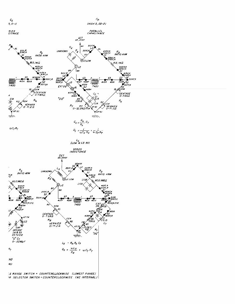
Cs !:1, 0-1)
RIES CITANCE
,R
BL
OET S3,204F
Cp
(HIGH 0, .02-2)
PARALLEL CAPACITANCE
S2 BL
:;~;;~ Sl
RA RATIO ARM
t'H 2/0F,R
RX 20/F,R
GY.
2t3F,R R 2sJ F,R RA'Ito ARM
2~1~~ 1113,/MIJ
~g~~~ St
413/;R 414F,R
S2,103R I'E ooc~r--4~--~~~.-~306~R
4/0R 40/R 52
CIA
~ R2
2 AT 50
RA
ccw CENT ADE O-T.6K.f2
ccw RN
VERNIER 0-71.2/J
''oo•
OET
Cx= RN CT RA
R2
ox=-~--GJCx Rx = c.J CTRT
Ls (LOW Q 0.5-50)
SERIES INOI./CTANCE
RA
~~~~ Rl3, IM.fJ
ccw VERNIER 0-71.2.fJ
403F;R 406F,R
I
RATIO ARM RATIO ARM
R7,Q982.11
412F,R 4/SF,R
514811,% 52
CAPT" OECAOE $4855 C5 TOC/2
C2
"o" cT o-.0298pF
'NO
NO
3/0F,R 52
307F,R
RO
BR
CENTAOE 0-7.6K.fJ
RN VERNIER o.-71.2.fJ
Lx = RN RA CT
Ox= wLx Rx
RT "oo"
~E RANGE SWITCH= COUNTERCLOCKWISE (LOWEST RANGE) 'R SELECTOR SWITCH= COUNTERCLOCKWISE (AC INTERNAL)
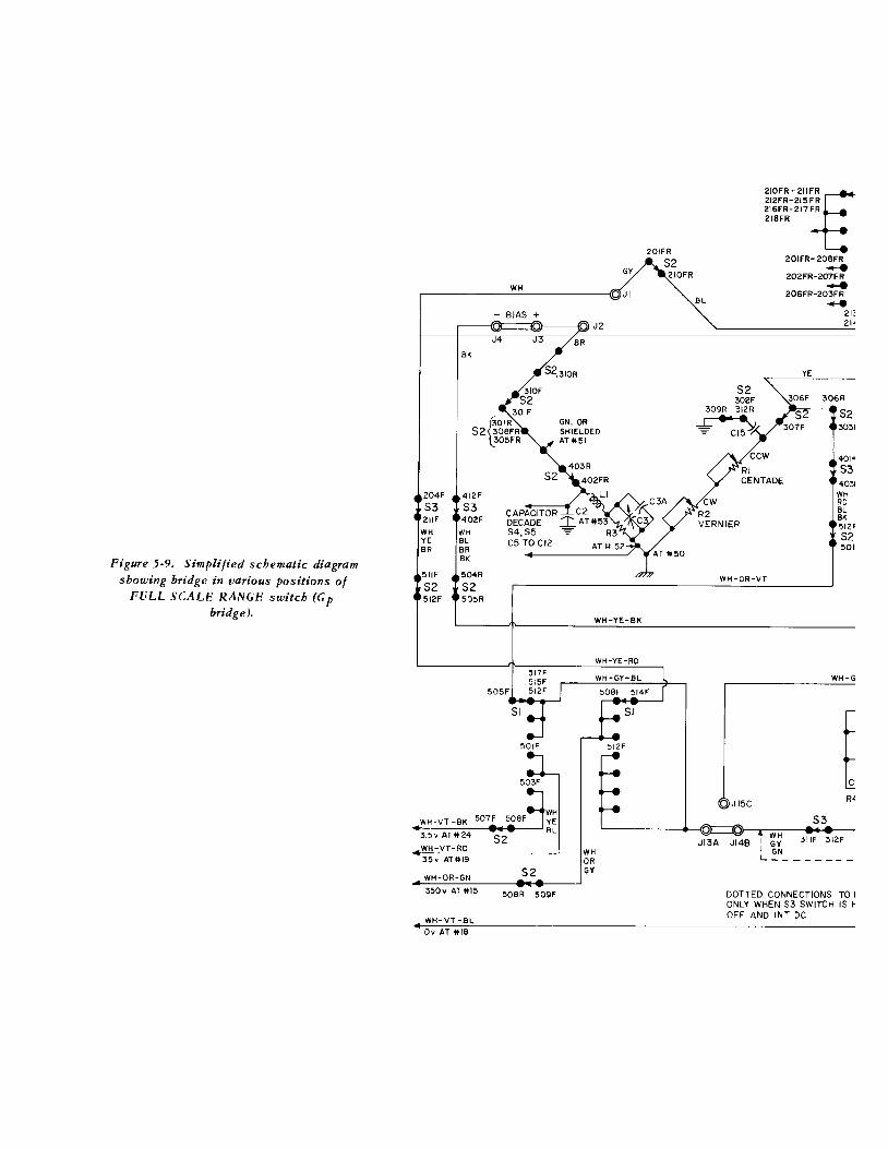
Figure 5-9. Simplified schematic diagram showing bridge in various positions of
p bridge).
BK
WH
- BIAS
J4
301F
~QIR
52 308FR 305FR
GN, OR SHIELDED AT4151
204F
53 211F
WH YE
412F
53 402F
WH
CAPACITOR C2 DECADE ~ AT4153 54,55 ~ R3
BR
511F
52 512F
BL BR BK
504R
52 505R
C5 TO Cl2
505F
51
50 IF
WH WH ·VT -BK 507F 508F YE
.,:_3:..:..5:..:.v:..:.A.,cT-41-'-::'24.,.-~·5•2•----' B L
WH-VT-RD 35v AHII9
WH-OR-GN 52 350v AT 4115 50BR 509F
WH-VT-BL
Ov AT 4118
WH-YE-BK
WH OR GY
512F
BL
CW
210FR-211F=E 212FR·215FR 216FR-217FR 218FR
201FR-208FR __. 202FR-207FR ..... 206FR-203FR ......
21: 21'
YE
52 3031
40\f'
53 4031
R2 VERNIER
WH RD BL BK 512f' 52 5011
JI3A
WH-OR-VT
WH-G
a Jl5c
53
Jl48 I WH 3IIF 312F I ~~ L--------
DOTTED CONNECTIONS TO I ONLY WHEN 53 SWITCH IS ~ OFF AND INT DC
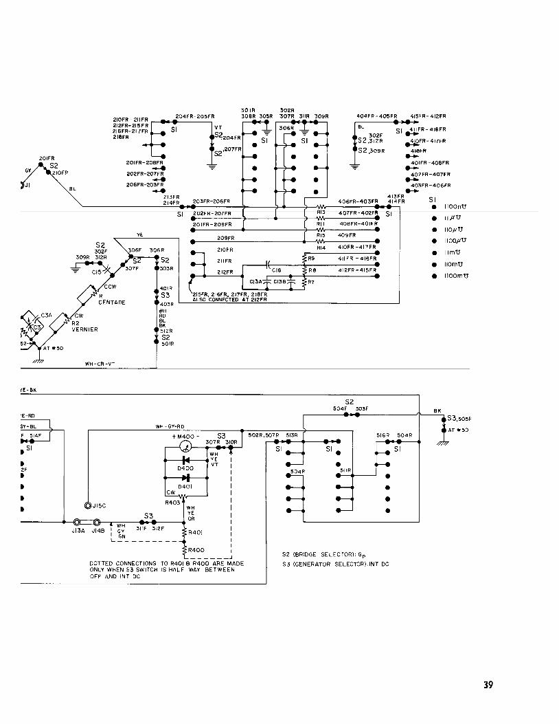
GY
Jl
IE-BK
• 51
• 2F • • • •
201FR
52 210FR
BL
0 JI5C
2IOFR _ 211 F R .--........ .._20_4_F_R_-_2_05_F...,R
:~~~~=~:~~~ 51 VT 218FR 5~204FR
201FR-208FR ...... 202FR-207FR ..... 206FR-203FR ......
213FR 214FR
YE
306R
52
303R
401R
53 403R WH RD BL BK 512R 52 501R
51
D401 cw
203FR-206FR
201FR-208FR
R401
301R 302R 308R 305R 307R 311R 309R
Rl5
Rl4
R9
RB
R7
502R,507R 513R
51 51
404FR- 405FR 415FR-412FR
BL
409FR
410FR -417FR
411 FR -416FR
412FR-415FR
52 504F 503F
• • 511R
51 ~R-416FR
~FR-417FR
418FR ... 401FR -408FR ... 402FR-407FR ..... 403FR -406FR .....
413FR 414FR 51
•
516R 504R
51
• • • •
• • • • • •
IIOOnU
li.UU
IIOpU
IIOO.UU
11mU
IIOmU
IIOOmU
R400 52 (BRIDGE SELECTOR): Gp
DOTTED CONNECTIONS TO R401 a R400 ARE MADE ONLY WHEN 53 SWITCH IS HALF WAY BETWEEN OFF AND INT DC
53 (GENERATOR SELECTOR): INT DC
39

506F
WH OR VT
507F WH-VT·BK
505F
WH-VT-RD
+35v AT #J9
WH-OR-GN
+350vAT#I5
WH -VT-BL
Ov AT#IB
40
ZOIFR S2 204FR
WH
R2 VERNIER
502R 512F
S2 509FR
WH-OR-GY 508F 514F
204FR·205FR
210FR, 211FR a 212FR} ALSO CONNECTED AT 215FR
VT
BL
CAPACITOR DECADE 54, 55 C5 TO Cl2
512R WH-RD-BL-BK
WH-GY-RD
0 Jl5 c S3
312R S2 303R
401R S3 403R
D400
cw D401
R403 WH YE
215FR
218FR
201FR- 208FR
WH-YE-GN
L_~~~--~~AwH~~~ OR
I I I
Jl3 A
R401 I I I
R400 :
-------- _j
DOTTED CONNECTIONS TO R401 8 R400 ARE MADE ONLY WHEN 53 SWITCH IS HALF WAY BETWEEN OFF AND INT DC
CI3A CI3B
502R 507R 513R
R7 412FR•
RB 411FR•
R9 410FR
RIO
Rl5 408FR•
Rll 407FR•
Rl3 406FR·
309R
213FR· 214FR 203FR·~
202FR-< ~ 201FR -2 ........ 209FR-; ~
:r210 21< 216 21E
• • • •
CHASSIS GROUND
AT #50 BRIDGE GR
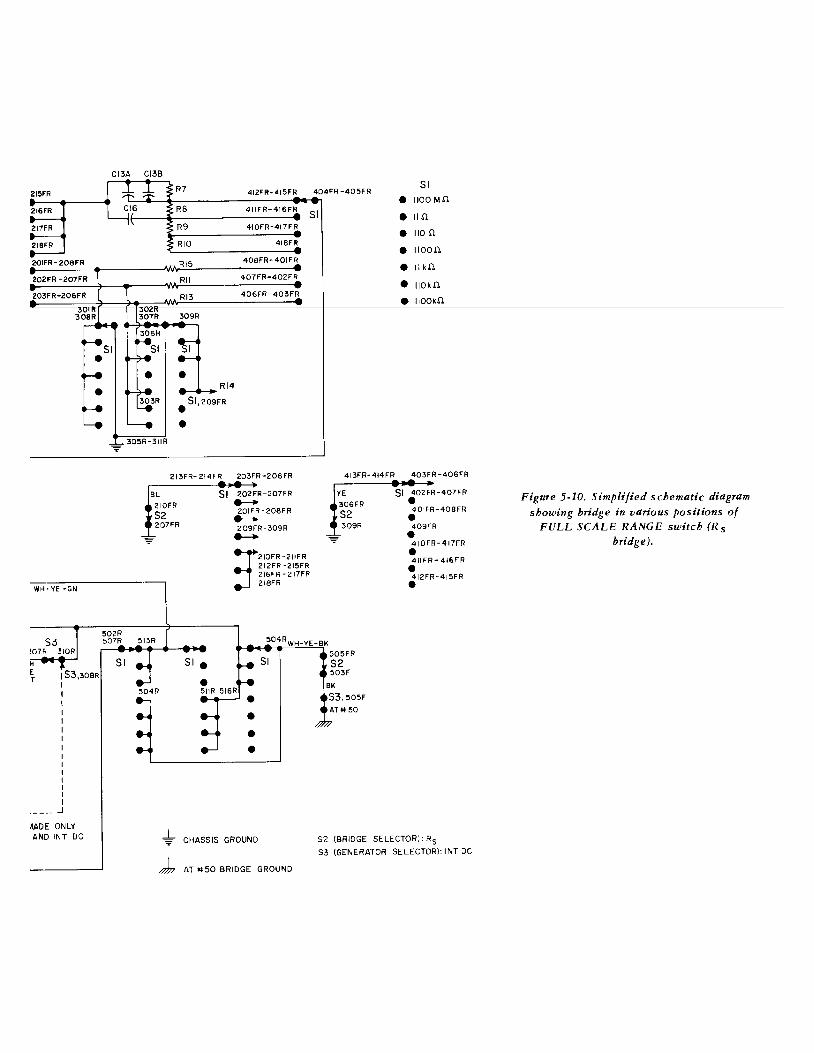
215FR
216FR
201FR- 208FR
WH·YE -GN
I I I I
·--- _j
MOE ONLY AND INT DC
CI3A CI3B
R7 412FR· 415FR 404FR·405FR Sl
• IIOOM.O. RB 411FR-416FR
Sl • 11.0. R9
RIO
213FR- 214FR
BL Sl 210FR
S2 207FR
410FR-417FR
418FI'!
408FR- 401 FR
407FR-402FR
406FR-403FR
203FR-206FR
202FR-207FR ~ 201FR-208FR ......... 209FR-309R ._
:f"'" _, "" 212FR-215FR 216FR-217FR 218FR
• • • •
CHASSIS GROUND
AT #50 BRIDGE GROUND
• 110 .0.
• 1100.0.
• II k.O.
• IIOk.O.
• IIOOk.O.
413FR-414FR 403FR-406FR
YE Sl 402FR-407FR • 401FR-408FR • 309R 409FR • q IQF!l-417f!l
• 411 FR- 416FR
• 412FR-415FR •
52 (BRIDGE SELECTOR): R5 53 (GENERATOR SELECTOR): INT DC
Figure 5-10. Simplified schematic diagram showing bridge in various positions of
FULL SCALE RANGE switch (Rs bridge!

Figure 5-11. Simplified schematic diagram showinf! bridf!e in various Positions of
SJ (function switch).
53 J 7 RD 504F -506f 506R-510R @~~--_.~----~~----
EXT GEN e 508R
@ • • JB
205R DE.T ATIO 37
203R DET AT +I 38
• • •
osc OUTPUT AT If 32
53 DET 304F 306F
AMP OUTPUT WH :J AT 1040 GN
8~ • • •
53 53 312F
AC EXT • --AC INT • • OFF • •
1 DC INT • ~ pc EXT • L~
CHASSIS GROUND
AT tt 50, BRIDGE GROUND
53 505R
S3,303R
Sl (FULL SCt
52 (BRIDGE S

4 I
I
: I I T400 I I I
>4 2
53 505R 5
AToll 51
- 52,305FR
t~530
~~ . GEN '33
LEVEL 09R AC·DC
-017
WH·YE-GY
03'l
AT#60
AT#62
WH·YE·OR
FULL SCALE RANGEl: 1/00m.O.
BRIDGE SELECTOR): R5
52 51 52 512R- 502R 514F-508F 509FR·507F
WH·RD·BL·BK WH·YE·RD WH·OR·GY WH·VT·BK AT #24 +3.5DC
504F ~04R-506R 513R· 507R
WH·BL·BR·BK WH·YE·GN WH·VT·BL AT +118 -35DC - - -
53 52 51 410R • 401R
L;
Ao • WH 403R - Jl
~ 406R - 0 J2
BIAS 52,303R
53 - + 409F -412F BK
J4 J3
~ -@:::::@-
• AT +I 50 ~
r .-7,;77
53 C5,76 206F - 204F
R~~2 T - -DET
~~~~T-= DET -SENS • AHI33 m.~(AC) 211F
~R 52 51 Jl3 Jl4
1 511F -501FR 505F-515F A B 0 0
WH WH WH
~ YE OR GY BR VT BL
c
M400 53 307R 305R DET
~- WH·YE·VT e • :J • AMP OUTPUT WH AT*41 RD D~OO ~~ WH 51 AT +161 .....
D401 • GY ....._ _310R RD 516R
..... AT#63 51/R
CWR403 301R
DET SENS (DC) : 308R
l ~53,309F I
..... ___________ ..J
R401 R400 DOTTED CONNECTIONS TO R401 6 R400 ARE MADE ONLY WHEN 53 SWITCH IS HALF WAY BETWEEN OFF AND INT DC
504R WH YW BK
WH·GY·GN
WH GY GN
53 52 BK 505F
505FR 50~
41

Cs •
Cp e Gp e
Rs •
Ls •
Lp e
42
AT *125 +4-~~----------------------,
IO~F ~OIF 104F POWER SUPPLY 20V DC
WH-BR
PI ~ON-OFF WH-BK
-~ AT#26
~
WH GN-BR
AC EXT
AC INT
OFF • • DC INT
DC EXT • • R303
t53,102F WH-YE
112R IIUbH
~:--..... R302
53 ~IOSF ~
-
WH GN BK
IV.,r IU.OI WH-OR
ALL NEGATIVE LAMP TERMINALS ARE COMMON
AND GROUNDED
,-------------W~H~-B~L~-~B~K ___________________ I_OI~~ 52 WH - T ~~ • 52 ..._J
WH -BL
WH-BL-BR
IP2 P3
~ ~ ~ '
P4 --- ~ / __ ,
P5 --, P6 7 --
/ " ' -3:S P7 "
/,...- "
~ IOBR -109R
I lOR
MU
GY VT
IIOOpF
II nF IIOnF
IIOOnF II )iF
IIO)JF
IIOO)JF
P9
PB
"' INDUCTIVE
~
----
115F
• •
II OF
107F
114F
WH-GN
WH-RD
WH-GY-BR
P13
Pl4 ~ L----'-P-'-15~------..-1~14-------+-.---J Pl6
Ill llollolloiiGII ~ ;> "
WH-GY-BK PIO Pll P12\
51e--~1-IZ~F~-----~W~H~-~R~D-~B~R~-------~ 113F WH-RD-BL
Q CAPACITIVE )
Figure 5-12. Simplified schematic diagram showing light circuits.
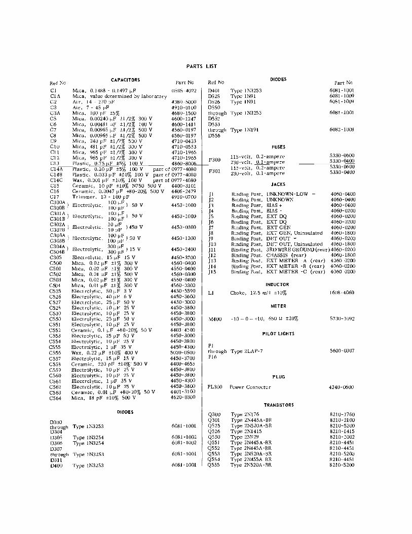
PARTS LIST
Ref No
Cl CIA C2 C3 C3A cs C6 C7 C8 C9 ClO Cll Cl2 Cl3
CAPACITORS
Mica, 0.1488 - 0.1497 jJF Mica, value determined by laboratory Air, 14 - 270 pF Air, 7 - 45 pF Mica, 100 pF ±5% Mica, 0. 00240 jJF ±l/2% 300 V Mica, 0.00481 jJF ±l/2% 100 V Mica, 0.00965 jJF ±1/2% 500 V Mica, 0.00965 jJF ±1/2% 500 V Mica, 240 pF ±1/2% 500 V Mica, 481 pF ±1/2% 300 V Mica, 965 pF ±l/2% 300 V Mica, 965 pF ±l/2% 300 V Plastic, 0. 7 5 F +5 100 V
Part No
0505-4022
4380-5000 4910-0100 4680-1500 4600-1247 4600-1411 4560-0197 4560-0197 4710-0423 4710-0553 4710-1965 4710-1965
Cl4A Cl4B Cl4C CIS Cl6 Cl7 C300A} C300B
Plastic, 0.20 jJF ±5% 100 V part of 0977-4080 Plastic, 0.033 jJF ±10% 100 V part of 0977-4080 Wax, 0.001 jJF ±10% 100 V part of 0977-4080 Ceramic, 10 pF ±10% N750 500 V 4400-3101 Ceramic, 0.0047 jJF +80-20% 500 V 4406-2479 Trimmer, 10 - 100 pF 4910-0700
Electrolytic, 100 !JF} 50 V 4450-1000 100 jJF
C30lA } Electrolytic, C301B
100 !JF} SO V 100 !JF
C302A . C302B } Electro! yt1c, 10 !JF }450 V
10 jJF C303A . C303B } Electrolync, 100 !JF} SO V
100 jJF
C304A } Electrolytic, C304B
300 !JF} IS V 300 jJF
C305 csoo C501 C502 C503 C504 C525 C526 C527 C528 C530 C550 C551 C552 C553 C554 C555 C556 C557 C558 C559 C560 C561 C562 C563 C564
D300 through D304 D305 D306 D307 through D311 D400
Electrolytic, 15 jJF 15 V Mica, 0.02 jJF ±1% 300 V Mica, 0.02 jJF ±1% 300 V Mica, O.Ol!JF ±1% SOOV Mica, 0.02 jJF ±1% 300 V Mica, 0. 01 jJF ±1% 500 V Electrolytic, 50 jJF 3 V Electrolytic, 40 jJF 6 V Electrolytic, 25 jJF 50 V Electrolytic, 10 jJF 25 V Electrolytic, 10 jJF 25 V Electrolytic, 25 jJF 50 V Electrolytic, 10 jJF 25 V Ceramic, 0.1 jJF +80-20% 50 V Electrolytic, 25 jJF 50 V Electrolytic, 10 jJF 25 V Electrolytic, 1 jJF 35 V Wax, 0.22 jJF ±10% 400 V Electrolytic, 15 jJF 15 V Ceramic, 220 pF ±10%" 500 V Electrolytic, 10 jJF 25 V Electrolytic, 10 jJF 25 V Electrolytic, 1 jJF 35 V Electrolytic, 10 jJF 25 V Ceramic, 0.01 !JF +80-20% 50 V Mica, 18 pF ±10% 500 V
Type 1N3253
Type 1N3254 Type 1N3254
Type 1N3253
Type 1N3253
DIODES
4450-1000
4450-0300
4450-1000
4450-2400
4450-3700 4560-0400 4560-0400 4560-0300 4560-0400 4560-0300 4450-5590 4450-3600 4450-3000 4450-3800 4450-3800 4450-3000 4450-3800 4403-4100 4450-3000 4450-3800 4450-4300 5020-0500 4450-3700 4400-4655 4450-3800 4450-3800 4450-4300 4450-3800 4401-3100 4620-0300
6081-1001
6081-1002 6081-1002
6081-1001
6081-1001
Ref No
D401 D525 D526 D550
Type 1N3253 Type 1N91 Type 1N91
DIODES
through Type 1N3253 D552 D553 through Type 1Nl91 D556
F300
F301
FUSES
115-volt, 0.2-ampere 230-volt, 0.1-am ere US-volt, 0.2-ampere 230-volt, 0.1-ampere
JACKS
Part No
6081-1001 6081-1009 6081-1009
6081-1001
6082-1008
5330-0600 5330-0400 5330-0600 5330-0400
Jl Binding Post, UNKNOWN-LOW 4060-0400 ]2 Binding Post, UNKNOWN 4060-0400 ]3 Binding Post, BIAS + 4060-0400 ]4 Binding Post, BIAS - 4060-0200 JS Binding Post, EXT DQ 4060-0200 ]6 Binding Post, EXT DQ 4060-0200 ]7 Binding Post, EXT GEN 4060-0200 ]8 Binding Post, EXT GEN, Uninsulated 4060-1800 ]9 Binding Post, DET OUT - 4060-0200 JlO Binding Post, DET OUT, Uninsulated 4060-1800 Jll Binding Post, 3RDWIREGROUND(rear)4060-0200 }12 Binding Post, CHASSIS (rear) 4060-1800 }13 Binding Post, EXT METER -A (rear) 4060-0200 Jl4 Binding Post, EXT METER -B (rear) 4060-0200 Jl5 Binding Post, EXT METER -C (rear) 4060-0200
Ll
INDUCTOR
Choke, 12.5 mH ±10%
METER
M400 -1o- o- +IO, 650 n ±20%
PILOT LIGHTS
Pl through Type 2LAP-7 Pl6
PL300 Power Connector
PLUG
TRANSISTORS
Q300 Q301 Q525 Q526 Q550 Q551 Q552 Q553 Q554 Q555
Type 2Nl76 Type 2N445A- BR Type 2N520A-BR Type 2Nl415 Type 2N929 Type 2N445A -BR Type 2N445A-BR Type 2N520A-BR Type 2N455A -BR Type 2N520A-BR
1608-4060
5730-1092
5600-0307
4240-0600
8210-1760 8210-2100 8210-5200 8210-1415 8210-1002 8210-4451 8210-4451 8210-5200 8210-4451 8210-5200

Ref No
Rl R2 R3 R4
RS
R6 R7 R8 R9 RIO R11 Rl3
RlS R16 R300 R301 R302 R303 R304 R306 R307 R309 R310 R311 R312 R314 R315 R316 R400 R401 R403 RSOO RSOl R502 R503 R,:>04 RSOS R525 R526 R527 R528
PARTS LIST (cont)
RESISTORS Part No
Assembly, 0- 7.6 kQ ±0.05% Assembly, 0 - 71.2 n ±2% Wire-Wound, 6.65 kQ ±0.05% POTENTIOMETER, 0 - 1.062 kQ ±2%
1608-2 700 1608-2070 0510-3940
part of 0977-4080 POTENTIOMETER, 0- 52.5 kQ ±2%
Film, 536 n Wire- Wound, Wire- Wound, Wire-Wound, Wire- Wound, Wire- Wound, Wire- Wound,
±1% 0.982 n ±O.OS% 9.o n ±0.02% 90 n ±0.02% 900 n ±0.02% 100 kQ ±0.02% 1 MQ ±0.025%
0
part of 0977-4080 6450-0536
part of 1608-2060 part of 1608-2060
1608-2060 part of 1608-2060
0510-3600 0510-3040
Wire-Wound, 10 kQ ±0.025% 0602-3052 POTENTIOMETER, 25 n ±10% 6050-0650 Composition, 10 n ±10% 1 W 6110-0109 Composition, 51 n ±5% 2 W 6120-0515 Composition, 270 n ±5% 1 W 6110-1275 Composition, 100 n ±5% 1/2 W 6100-11 OS Composition, 390 n ±5% 1/2 W 6100-1395 Composition, 250 kQ ±10% part of 1608-4040 Composition, 100 kQ ±5% 2 W 6120-4105 Composition, 2.5 kQ ±10% part of 1608-4040 Composition, 20 kQ ±5% 1/2 W 6100-3205 Composition, 2.4 kQ ±5% 1/2 W 6100-2245 Composition, 1 kQ ±5% 2 W 6120-2105 Composition, 22 kQ ±5% 1/2 W 6100-3225 Composition, 100 n ±5% 1/2 W 6100-1105 Composition, 10 n ±5% 2 W 6120-0105 Composition, 4.7 kQ ±5% 1/2 W 6100-2475 Composition, 47 kQ ±5% 1/2 W 6100-3475 POTENTIOMETER. 5 kQ ±5% 0971-4210 Film, 8.25 kQ ±1% 1/4 W 6350-1825 Film, 7.68 kQ ±1% 1/4 W 6350-1768 Film, 15.8 kQ ±1% 1/4 W 6350-2158 Film, 15.8 kQ ±1% l/4 W 6350-2158 Film, 7.87 kQ ±1% 1/4 W 6350-1780 POTENTIOMETER, 1 kQ ±20% 6040-0400 Composition, 3 kQ ±5% 1/2 W 6100-2305 Composition, 22 kQ ±5% 1/2 W 6100-3225 Composition, 62 n ±5% 1/2 W 6100-0625 Composition, !SOn ±5% 1/2W 6100-1155
Ref No
R529 R530 R531 R532 R533 RSSO RSSl R552 R553 R554 RSSS R556 R557 R558
R560 R561 R562 R563 R564 R565 through R568 R569 R570 R571 R572 R573 R574 R575 R576
S1 S2 S3 S4 ss
T300 T400
RESISTORS Part No
POTENTIOMETER, 1 Hl ±20% 6040-0400 Composition, 62 n ±5% 1/2 W 6100-0625 Composition, 22 kQ ±5% 1/2 W 6100-3225 Composition, 6.8 kQ ±5% 1/2 W 6100-2685 Composition, 500 n ±10% part of 1608-4040 Composition, 100 kQ ±5% 1/2 W 6100-4105 Composition, 47 kQ ±5% 1/2 W 6100-3475 Composition, 20 kQ ±5% 1/2 W 6100-3205 Composition, 1 kQ ±5% 1/2 W 6100-2105 Composition, 10 kQ ±5% 1/2 W 6100-3105 Composition, 4.7 kQ ±5% 1/2 W 6100-2475 Composition, 10 kQ ±5% 1/2 W 6100-3105 Composition, 100 kQ ±5% 1/2 W 6100-4105 Composition, 10 kQ ±5% 1/2 W 6100-3105
Composition, 100 kQ ±5% 1/2 W Composition, 22 kQ ±5% 1/2 W POTENTIOMETER, 50 kQ ±10% Composition, 100 kQ ±5% 1/2 W Colllposition, 1 kQ ±5% 1/2 W
Composition, 4.7 kQ ±5% 1/2 W
Composition, 1 kQ ±5% 1/2 W Composition, 150 kQ ±5% 1/2 W Composition, 18 kQ ±5% 1/2 W Composition, 4. 7 kQ ±5% 1/2 W Composition, 4.7 kQ ±5% 1/2 W Composition, 10 kQ ±5% 1/2 W Composition, 10kQ ±5% l/2W Composition, 1 kQ ±5% 1/2 W
SWITCHES
Rotary Wafer, BRIDGE SELECTOR Rotary Wafer, FULL SCALE RANGE Rotary Wafer, Function Rotary Wafer, GEN LEV Rotary Wafer, DET SENS
TRANSFORMERS
6100-4105 6100-3225 6030-0350 6100-4105 6100-2105
6100-2475
6100-2105 6100-4155 6100-3185 6100-2475 6100-2475 6100-3105 6100-3105 6100-2105
7890-2100 7890-2110 7890-2120 7890-2130 7890-2140
0345-4790 0746-4360
Rotary switch sections are shown as viewed from the panel end of the shaft. The first digit of the contact number refers to the section. The section nearest the panel is 1, the next section back is 2, etc. The next two digits refer to the contact. Contact 01 is thefirstpositionclockwise from a strut screw (usually the screw above the locating key), and the other contacts are numbered sequentially (02, 03, 04, etc), proceeding clockwise around the section. A suffix F or R indicates that the contact is on the front or rear of the section, respectively.

ro S3, 4t2F OWG 1608-60)
Figure 5·13. Schematic diagram of bridge circuits.
ro S3 ,204F --w""H~ (SE£ OWG 1608-60)
BIAS
52,30/R
BR
RO
$2 3/0R
3/0F
204FBR vr

vr
C/3 :;;~ R7 ,7S ~982
RIS IOK
,___.._____.
Rll lOOK . R/3 IM
~C/6
0047 _ll /I
R8 9 •
R9 90 •
RIO 900
-
L.------~'r--------'1~1~~~~,~~-~~---~--~ '-----'l~Jl~~~~qj~~~~~y~~-~---~ ~ "
~ . - -------- -- --- -- -- -- - ------ ,J
-
f!Jl" .... o _____ r---__ G_N __ ..,. TO S3,401R
(SHI£L0£0 LEADS) ol ~OR \J 306R !t--ATS/
----Jfl..--------------4 52, 305F8R
o r 1 o
R/4 IK
Sf
/;'b,.. ~1XTDO / ~- r;;\ o JS 21/F ;;\....,_. ____________ ....,
) 0 404 ,[]")+!~ ~)if\ 0'Y FSR J6 ~~ 202F
,o;T\/. C6 ~;._/1.,. o
0
. 00481 "'o'/Cf-'<' o" ( c\J~
$4111/R
I CS-::
.00240,...._ I
I IS4
I I
I ~~~20~/~R------~--~ I o\ I f/o loA.' -'- 203R
~~- ,(1 -t2o4R
I "'c{ 71 C7 :::(:::: V ~ .... P ~ ' Jeo96ti
•J C8 iT . 0096S S4
I02R
S4,104R S4,103R
BL
Y£
21/F "~~T 1" ._ \_ 'K_. 202F 0 0
.... z .... :; w...<l ----;:
r/j ~0 :;:::;: CIO (, \ 1 P
481 J
SS,IIIR
I I I iSS I I
C9 ;:~ 240
I ~'·2~0~/~R---------'l'~~ I o \ T (/o 1
0'-, -'- -"203R
: ~: -<)
1204R
Vo"'\l.?~o •J -,-
CI21CII,. .... 96S 96S
S5,104R S5,103R S5,102R
43
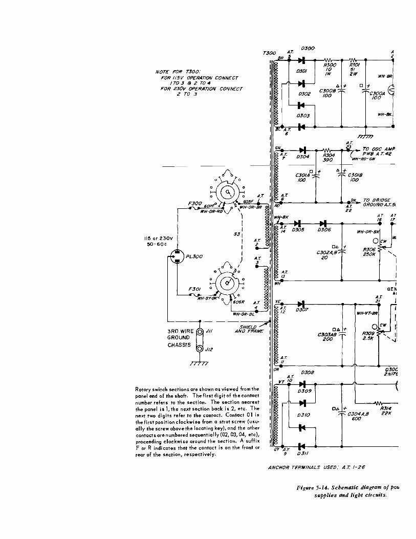
lJ.J(}G-T300 A.T. A
$ 2
NOT£ FOR T300: FOR IISV OPERATION CONNECT
IT03 8 2 T04 FOR 230V OPERATION CONNECT
2 TO 3
115 or 230V 50-60C
3RD WIRE GROUND
CHASSIS
SHIELD AND FRAME
Rotary switch sections are shown as viewed from the panel end of the shaft. The first digit of the contact number refers to the section. The section nearest the panel is 1, the next section back is 2, etc. The next two digits refer to the contact. Contact 01 is the first position clockwise from a strut screw (usually the screw above the locating key), and the other contacts are numbered sequentially (02, 03, 04, etc), proceeding clockwise around the section. A suffix For R indicates that the contact is on the front or rear of the section, respectively.
BR
A.Z"
0301
D302 C3008
D303
C301A0 +
100
100
t:. +
t:. +
a
C3018 /00
WH-BR
+ C300A 100
WH-
':tB._ ____ .._ ___ ._e!!B!!,1(~ TO BRIDGE RO A.T GROUNDA.T.Sj
22 A.T. A.7
lllrLe---l~---l~-~~----~1e6 17
WH
A.T 13
A.T. II
OR A.T.
vr to
Gr A.T
D308
D309
D310
D306
Ct. + C302A,B
20
Ct. + C303AB
200
Ct. +
R306 250K
A.T: 21
' ' I
I I I
GEN AC
Q30G 2NI7f
R314 C304A,B 22K
600
9 D311
ANCHOR TERMINALS USED: A.T. 1-26
Figure 5-14. Schematic diagram of por. supplies and light circuits.
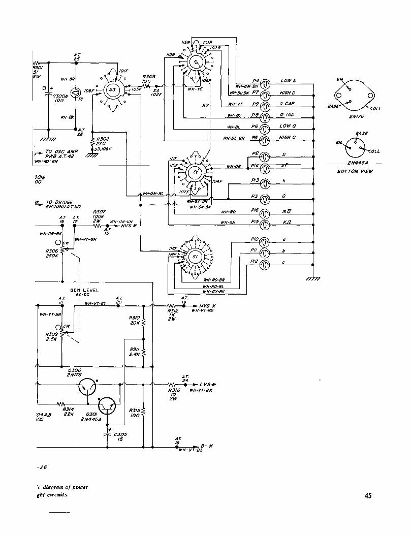
9301 51 ew
A.T. 25
WH-BR
a + C300A 100
WH-8/(._
1---+-------A.T. 26
.,....- TO OSC AMP PWB A.T.42
"WH-RO-GN
~OIB 00
~K TO BRIDGE -- GROUNDA.T.50
R307 A.T A.T. lOOK /6 17 2W WH-OR-GN
___ __. ._--Wv-.__HVS * WH-OR-BK
Ocw R306 250K
A.T
WH-VT-GN
I GEN LEVEL
A C-DC
A.T 15
21 WH-VT-GY
WH-VT-BR
0 cw R309 ....
' I 2.5K -.J
()300 2NI76
"04A,B 100
-26
!c diagram of power ght circuits.
A.T. 20
R310 20K
R311 2.4K
R315 100
P4 LOWD
Q WH-6N-BR S3 WH-BL-BK P7 HIGHD 102F
WH-VT P9 Q CAP BAS OLL
WH-GY P8 () IND 2NI76
WH-BL P6 LOW Q
WH·BL-BR P5 HIGH()
~ OLL
BOTTOM VIEW
WH-GN-BL
a
" c
WH-Ro-BL WH-GY-BK
A.T. 19
MVS Jf R312 WH-VT-RO IK
2W
A.T. 24
LVS* R316 WH-VT-BK 10
2W
A.T. 18
45
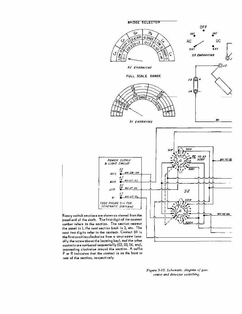
BRIDGE SELECTOR
52 ENGRAVING
FULL SCALE RANGE
S/ ENGRAVING
POWER SUPPLY 8 LIGHT CIRCUIT
A.r
HVS '! WH-OR-GN -A.T
MVS '! WH- VT-!TD
A.T
LVS 2..4 WH-VT·BK
A.T
B- '1. WH-VT-BL
(SEE FIGURE 5-11 FOR SCHEMATIC OfA(;frAM)
are shown as viewed from the Rotary switch sections panel end of the shaft. number refers to the s the panel is 1, the next next two digits refer to the first posit ion clockw ally the screw above th
The first digit of the contact ection. The section nearest section back is 2, etc. The the contact. Contact 01 is i se from a strut screw ( usu-
e locating key), and the other contacts are numbered sequentially (02, 03, 04, etc), proceeding clockwise around the section. A suffix F or R indicates that the contact is on the front or rear of the section, respectively.
INT • OFF •
AC /
EXT
INT • DC
• EXT
5.3 ENGRAVING
r---------{0 .12
.1.3 +
.14
BK
51/F i.~-;\ 50/F ~ 11 ,.0
:£~~TOS3 WH-Y£-Rl ~ ~~-~ S05F .------4; ~·
/•./ly~~ / 1\
(
S2
"\ 50/R
~~ ,~
~,.~ WH-Y£-GN y,_
/ \ -v/ '\ 506R
Figure 5-15. Schematic diagram of generator and detector switching.

IIOGE SELECTOR
ENGRAVING
.L SCALE RANGE
' ENGRAVING
I·GN
·liD
·BK
'•BL
)mthe mtact tarest • The 01 is (usuother
, etc), suffix ont or
INT • •
AC /
EXT
DC
• EXT
53 ENGRAVING
J3 +
J4
BK
WH·YE-RD
BRIDGE
(SEE 1608-4D FOR 52, DETAIL OF BRIDGE) 3031f
WH-YE-BR
(t---~--------~~~1U~--------~W~H~-Y.~~~-~8~L------~~_j WH-OR-GY
WH-GY·RD
WH-OR-VT
S2
Figure 5-15. Schematic diagram of generator and detector switching.
HIH-81..- BR-BK
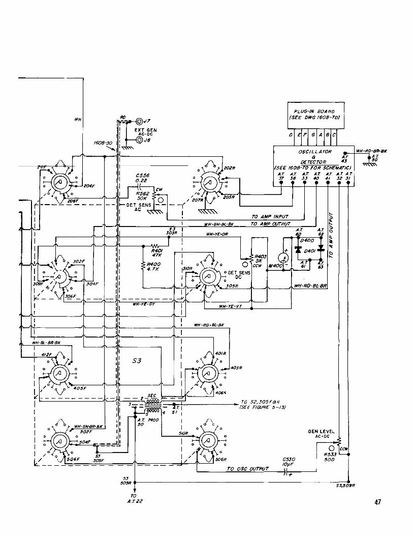
-----------------
-..
WH ;..,.-@J7 :I EXT GEN 1 r ~-DC
PLUG-IN BOARD (SEE DWG 1608-7D)
1608-30 1 : r 4 Js ~~~~~ OSCILLATOR -e-+W;;..:.H:....-:..:.;RD-BR-BK
DETE~TOR :J J1f ,/\, I I f' I (SEE 1608-70 FOR SCHEMATIC)
A.T. A.T. A.T. A.T. A.T. A.T. A.T. .y 38 3! 40 41 32 31
~H-Bl.- BR-BK
,, I
I I
: "" J"-,J ::
WH-YE-GY
S3
,. • I' ' 4' ' I
WH-YE-VT
WH-RD-BL-BK
~~:'®-; ii I 6< .~~-------J~~~--------_J~~ I ./ \../ 405F I I it - - - - - - - - - - -- ~~ I ,, I 'I I 'I I 0 '\ i"\.,. WH-GN-BR-BK. : I I \ I,. 502F ,,
I ~- ~\~504F J: I o ... ~ 1 - =~ I /o<q o S3
lL"-- ~ 506F 505F
SEC -- 2 :-iln'Mn ,_
3 .~ ~r-~
r--4~;vvvv 4
A.T. 7"400 50
• TO S2,305F8R (SEE FIGURE 5-13)
TO OSC OUTPUT
C530 /OpF \I II+
GEN LEVEL A C-DC
0 ccw R533 '--500
53 505R.---------------------------------------------------------S-~-5409R
TO A.T22 47
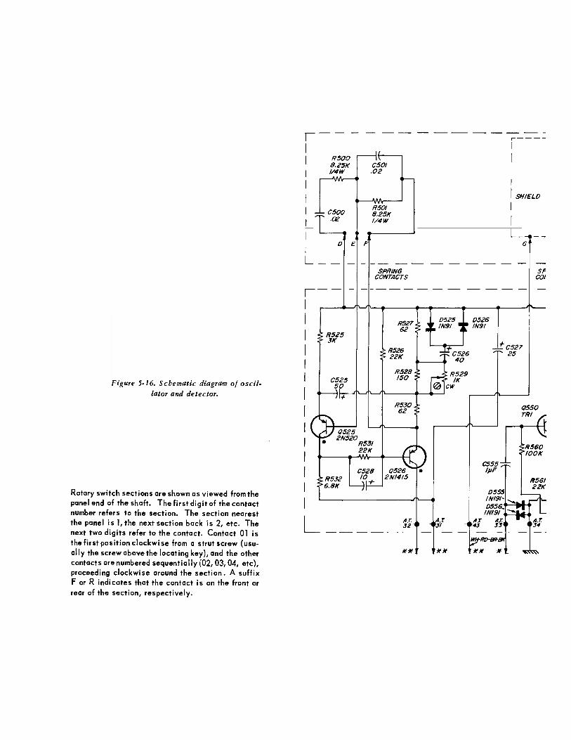
Figure 5-16. Schematic diagram of oscillator and detector.
Rotary switch sections are shown as viewed from the panel end of the shaft. The first digit of the contact number refers to the section. The section nearest the panel is 1, the next section back is 2, etc. The next two digits refer to the contact. Contact 01 is thefirstpositionclockwise from a strut screw (usually the screw above the locating key), and the other contacts are numbered sequentially (02, 03, 04, etc), proceeding clockwise around the section. A suffix For R indicates that the contact is on the front or rear of the section, respectively.
,---------1
I
I I L
RSOO 8.25K I/4W
0 £
CSOI .02
RSOI 8.25K 1/4W
SPRING CONTACTS ,--
1
I I I I I I I I I I I I I
R525 3K
C525 50
+
()525 2N520
R531 22K
C528 10
+
R526 22K
()526 2N/415
L A.T. :J2
------
**
+C526 40
R529 IK
CW
0526 IN91
A.T A.T 31 >6
** **
r----
1
I
I
I SHI£LO
I I L_
G
+cs27 25
SP co~
()550 TRI
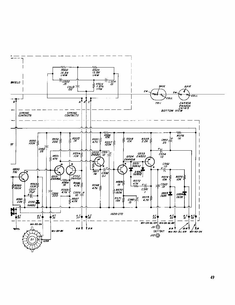
, __
IHIELO
G
SPRING CONTACTS
R550 lOOK
A.T. 36
R502 15.8K 1/4W
C502 .01
C503 .02
A
SPRING CONTACTS
A.T. 37'
** WH-BR-IJK
c
A.r. 38
R503 15.8K I/4W
)flf
C504 .01
1608-272
BASE
TR-1 2N445A 2N520A 2NI415
BOTTOM VIEW
R576 C553 + IK 25
A.r. 40
A.T. 41
WH-GN·m;:R Q WH-GN-:·;K ~ ~
DETOUT WH·RO-BL-BR WH·RD-GN
Jlo@
49