imperial rear-engine riders - ariensapache.ariens.com/manuals/02758400b_eng.pdf · embrayage de...
TRANSCRIPT

ENGLISH
FRANÇAIS
ESPAÑOL
Owner/Operator Manual
Models
927046 - RM1028927055 - RM1332927056 - RM1330
02758400B 4/02Supercedes 02758400,A
Printed in USA
Imperial
™
Rear-Engine Riders
3
ENGLISH
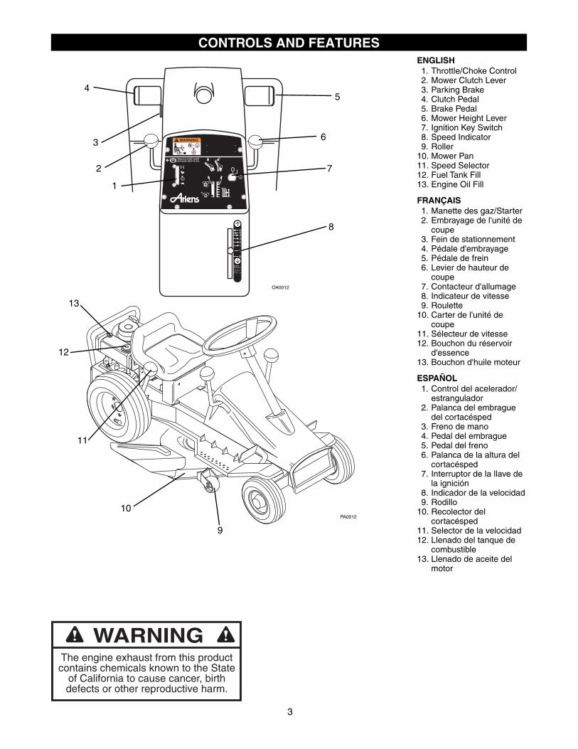
1. Throttle/Choke Control2. Mower Clutch Lever3. Parking Brake4. Clutch Pedal5. Brake Pedal6. Mower Height Lever7. Ignition Key Switch8. Speed Indicator9. Roller
10. Mower Pan11. Speed Selector12. Fuel Tank Fill13. Engine Oil Fill
FRANÇAIS
1. Manette des gaz/Starter2. Embrayage de l'unité de
coupe3. Fein de stationnement4. Pédale d'embrayage5. Pédale de frein6. Levier de hauteur de
coupe7. Contacteur d'allumage8. Indicateur de vitesse9. Roulette
10. Carter de l'unité de coupe
11. Sélecteur de vitesse12. Bouchon du réservoir
d'essence13. Bouchon d'huile moteur
ESPAÑOL
1. Control del acelerador/estrangulador
2. Palanca del embrague del cortacésped
3. Freno de mano4. Pedal del embrague5. Pedal del freno6. Palanca de la altura del
cortacésped7. Interruptor de la llave de
la ignición8. Indicador de la velocidad9. Rodillo
10. Recolector del cortacésped
11. Selector de la velocidad12. Llenado del tanque de
combustible13. Llenado de aceite del
motor
CONTROLS AND FEATURES
R
N
123456
SpeedSelectorLocated onr ight handside ofdr iver 's seat
Depress clutch pedaland push latch to set.P
WARNING
2
3
45
6
7
8
9
10
11
12
13
OA0012
PA0012
1
The engine exhaust from this productcontains chemicals known to the State
of California to cause cancer, birthdefects or other reproductive harm.
WARNING

GB - 4
Controls and Features . . . . . . . . . . . . . . . . . . . . . 3
Safety . . . . . . . . . . . . . . . . . . . . . . . . . . . . . . . . . . 5
Operation . . . . . . . . . . . . . . . . . . . . . . . . . . . . . . . 9
Service and Adjustments . . . . . . . . . . . . . . . . . 12
Storage . . . . . . . . . . . . . . . . . . . . . . . . . . . . . . . . 21
Troubleshooting . . . . . . . . . . . . . . . . . . . . . . . . . 22
Service Parts . . . . . . . . . . . . . . . . . . . . . . . . . . . 22
Attachments . . . . . . . . . . . . . . . . . . . . . . . . . . . . 22
Accessories . . . . . . . . . . . . . . . . . . . . . . . . . . . . 22
Specifications. . . . . . . . . . . . . . . . . . . . . . . . . . . 23
Warranty . . . . . . . . . . . . . . . . . . . . . . . . . . . . . . . 24
THE MANUAL
Before operation of unit, carefully and completely read your manuals. The contents will provide you with an understanding of safety instructions and controls during normal operation and maintenance.
All reference to left, right, front, or rear are given from operator sitting in operation position and facing the direction of forward travel.
MODEL AND SERIAL NUMBERS
When ordering replacement parts or making service inquiries, know the Model and Serial numbers of your unit and engine.
Numbers are located on the product registration form in the unit literature package. They are printed on a serial number label, located on the frame of your unit.
• Record Unit Model and Serial numbers here.
• Record Engine Model and Serial numbers here.
PRODUCT REGISTRATION
A warranty registration card must be filled out, signed, and returned at time of purchase. This card activates the warranty. Claims meeting requirements during limited warranty period will be honored.
UNAUTHORIZED REPLACEMENT PARTS
Use only Ariens replacement parts. The replacement of any part on this vehicle with anything other than an Ariens authorized replacement part may adversely affect the performance, durability, or safety of this unit and may void the warranty. Ariens disclaims liability for any claims or damages, whether warranty, property damage, personal injury or death arising out of the use of unauthorized replacement parts.
For a brief list of replacement parts see
Service Parts
in this manual. To obtain a complete parts manual, find your model and serial number. Then go to www.ariens.com or call 1-800-678-5443.
DISCLAIMER
Ariens reserves the right to discontinue, make changes to, and add improvements upon its products at any time without public notice or obligation. The descriptions and specifications contained in this manual were in effect at printing. Equipment described within this manual may be optional. Some illustrations may not be applicable to your unit.
DELIVERY
Customer Note:
If you have purchased this product without complete assembly and instruction by your retailer, it is your responsibility to:
1. Read and understand all assembly instructions in this manual. If you do not understand or have difficulty following the instructions, contact your nearest Ariens Dealer for assistance.
Make sure all assembly has been properly completed.
NOTE:
To locate your nearest Ariens Dealer, call 1-800-678-5443 or go to www.ariens.com on the inter-net.
TABLE OF CONTENTS
INTRODUCTION
Transfer model & serial number label from product registration
here.
Serial Number Label
OA0041Figure 2

GB - 5
2. Understand all Safety Precautions provided in the manuals.
3. Review control functions and operation of the unit. Do not operate unit unless all controls function as described in this manual.
4. Review recommended lubrication, maintenance and adjustments.
5. Review Limited Warranty Policy.
6. Fill out Original Purchaser Registration Card and return the card to Ariens Company.
SAFETY ALERTS
Look for these symbols to point out important safety precautions. They mean:
Attention!
Personal Safety Is Involved!
Become Alert!
Obey The Message!
The safety alert symbols above and signal words below are used on decals and in this manual.
Read and understand all safety messages.
NOTATIONS
NOTE:
General reference information for proper opera-tion and maintenance practices.
IMPORTANT:
Specific procedures or information required to prevent damage to unit or attachment.
PRACTICES AND LAWS
Practice usual and customary safe working precautions, for the benefit of yourself and others. Understand and follow all safety messages. Be alert to unsafe conditions and the possibility of minor, moderate, or serious injury or death. Learn applicable rules and laws in your area. Always follow the practices set forth in this manual.
REQUIRED OPERATOR TRAINING
Original purchaser of this unit was instructed by the seller on safe and proper operation by the seller. If unit is to be used by someone other than original purchaser; loaned, rented or sold, ALWAYS provide this manual and any needed safety training before operation.
SAFETY DECALS AND LOCATIONS
ALWAYS replace missing or damaged Safety Decals. Refer to figure below for Safety Decal locations.
1. WARNING
Be sure speed selector is in Neutral (N) and Mower
Clutch is disengaged ( ) before starting engine ( ).
2. DANGER!
Always keep feet and hands away from rotating parts.
Always stand clear of the discharge area when operating this unit.
WARNING:
Improper assembly or adjustments can cause serious injury.
SAFETY
DANGER:
IMMINENTLY HAZARDOUS SITUATION! If not avoided, WILL RESULT in death or serious injury.
WARNING:
POTENTIALLY HAZARDOUS SITUATION! If not avoided, COULD RESULT in death or serious injury.
CAUTION:
POTENTIALLY HAZARDOUS SITUATION! If not avoided, MAY RESULT in minor or moderate injury. It may also be used to alert against unsafe practices.
OA0032
WARNING/AVERTISSEMENT/ADVERTENCIADo not operate mowerunless guards are inoperating position orbagger is attached.
Ne jamais utiliserla tondeuse sansprotecteur sur lecanal d'ejection ousans le bac monte.
No operar segadora amenos que las defensasesten en posicion deoperacion o elrecogedor este fijo.07742300B
DANGER/PELIGRO
07731400D
DANGER/PELIGRO
07731400D
DANGER / PELIGRO
TO AVOID SERIOUS INJURY OR DEATH
POUR EVITER LES BLESSURES GRAVES OU LA MORT
PARA EVITAR DAÑOS SERIOS O LA MUERTE• Leer el manual del operador.• Mantenga la unidad alejada de los niños u otras personas cuando esté en
funcionamiento.• Antes y durante retroceso mirar hacia abajo y detras.• Nunca monten niños.• Remueva objetos que puedan ser lanzados por la cuchilla.• Suba y baje pendientes, no transversalmente.• Si la maquina se detiene subiendo cuesta, desactive la cuchilla y baje
lentamente.• Evite viradas subitas.• Mantenga artefactos de seguridad (defensas, protectores, interruptores,
etc.) en su lugar y trabajando.• Verifique en el manual el sistema de engranar antes de usar.• Tenga conocimiento de funciones y localizaciones de todos los controles.
• Lire le manuel d'utilisation.• Éloigner les enfants et toute autre personne pendant le fonctionnement de la
machine.• Regardez derriere et sur les cotes lorsque vous reculez.• Ne transportez jamais dénfant.• Ne jamais décharger directement en direction de quelqu’un. Des particules
projetées peuvent provoquer des blessures.• Tondez toujours de haut en bas et inversement jamais le long des pentes.• Si la machine sárrete en montee. Debrayez la lame et redescendez
doucement.• Evitez les virages brusques.• Maintenez toujours en place tous les elements de securite (protecteurs,
interupteurs, etc.).• Controlez le bon fonctionnement des interrupteurs de securité avant
utilisation tel q'uindiqué dans le manuel d'utilisation.• Comprenez bien la fonction et la situation de chacun des leviers et boutons de
commande.
MAX 1
• Read the operator's manual.• Keep children and others away from unit while operating.• Look down and behind before and while backing.• Never carry children.• Never direct discharge toward other people. Thrown objects
can cause injury.• Go up and down slopes, not across.• If machine stops going uphill, stop blade and back down slowly.• Avoid sudden turns.• Keep safety devices (guards, shields,switches, etc.) in place and working.• Check interlock system per manual before use.• Understand location and function of all controls.
0773
9000
B
WARNINGAVERTISSEMENTADVERTENCIA
08093500
Figure 3
1
2
4
3
2
WARNINGAVERTISSEMENTADVERTENCIA
OL3030
OL0910
GB - 6
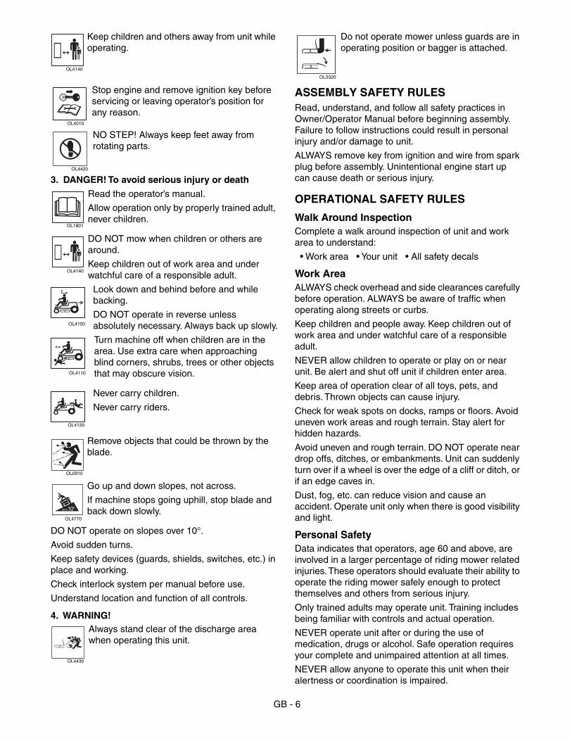
Keep children and others away from unit while operating.
Stop engine and remove ignition key before servicing or leaving operator’s position for any reason.
NO STEP! Always keep feet away from rotating parts.
3.
DANGER! To avoid serious injury or death
Read the operator’s manual.
Allow operation only by properly trained adult, never children.
DO NOT mow when children or others are around.
Keep children out of work area and under watchful care of a responsible adult.
Look down and behind before and while backing.
DO NOT operate in reverse unless absolutely necessary. Always back up slowly.
Turn machine off when children are in the area. Use extra care when approaching blind corners, shrubs, trees or other objects that may obscure vision.
Never carry children.
Never carry riders.
Remove objects that could be thrown by the blade.
Go up and down slopes, not across.
If machine stops going uphill, stop blade and back down slowly.
DO NOT operate on slopes over 10°.
Avoid sudden turns.
Keep safety devices (guards, shields, switches, etc.) in place and working.
Check interlock system per manual before use.
Understand location and function of all controls.
4. WARNING!
Always stand clear of the discharge area when operating this unit.
Do not operate mower unless guards are in operating position or bagger is attached.
ASSEMBLY SAFETY RULES
Read, understand, and follow all safety practices in Owner/Operator Manual before beginning assembly. Failure to follow instructions could result in personal injury and/or damage to unit.
ALWAYS remove key from ignition and wire from spark plug before assembly. Unintentional engine start up can cause death or serious injury.
OPERATIONAL SAFETY RULES
Walk Around Inspection
Complete a walk around inspection of unit and work area to understand:
• Work area • Your unit • All safety decals
Work Area
ALWAYS check overhead and side clearances carefully before operation. ALWAYS be aware of traffic when operating along streets or curbs.
Keep children and people away. Keep children out of work area and under watchful care of a responsible adult.
NEVER allow children to operate or play on or near unit. Be alert and shut off unit if children enter area.
Keep area of operation clear of all toys, pets, and debris. Thrown objects can cause injury.
Check for weak spots on docks, ramps or floors. Avoid uneven work areas and rough terrain. Stay alert for hidden hazards.
Avoid uneven and rough terrain. DO NOT operate near drop offs, ditches, or embankments. Unit can suddenly turn over if a wheel is over the edge of a cliff or ditch, or if an edge caves in.
Dust, fog, etc. can reduce vision and cause an accident. Operate unit only when there is good visibility and light.
Personal Safety
Data indicates that operators, age 60 and above, are involved in a larger percentage of riding mower related injuries. These operators should evaluate their ability to operate the riding mower safely enough to protect themselves and others from serious injury.
Only trained adults may operate unit. Training includes being familiar with controls and actual operation.
NEVER operate unit after or during the use of medication, drugs or alcohol. Safe operation requires your complete and unimpaired attention at all times.
NEVER allow anyone to operate this unit when their alertness or coordination is impaired.
OL4140
OL4010
OL4420
OL1801
OL4140
OL4100
OL4110
OL4120
OL0910
10°MAX
OL4770
OL4430
OL3320

GB - 7
Wear adequate safety gear and protective gloves. Wear proper footwear to improve footing on slippery surfaces.
DO NOT wear loose clothing or jewelry and tie back hair that may get caught in rotating parts.
Protect eyes, face and head from objects that may be thrown from unit. Wear appropriate hearing protection. Always wear safety goggles or safety glasses with side shields when operating mower.
Avoid sharp edges. Sharp edges can cut. Moving parts can cut off fingers or a hand.
ALWAYS keep hands and feet away from all rotating parts during operation. Rotating parts can cut off body parts.
ALWAYS keep hands away from all pinch points.
DO NOT touch unit parts which might be hot from operation. Allow parts to cool before attempting to maintain, adjust or service.
NEVER place your hands or any part of your body or clothing inside or near any moving part while unit is running.
NEVER direct discharge towards persons or property that may be injured or damaged by thrown objects. Use extreme caution on gravel surfaces. Stay alert for hidden hazards or traffic.
ALWAYS stand clear of the discharge area.
Fumes from engine exhaust can cause injury or death. DO NOT run engine in an enclosed area. Always provide good ventilation.
ALWAYS disengage attachment, stop unit and engine, remove key and allow moving parts to stop before leaving operator’s position.
Operation
Understand:
• How to operate all controls• The functions of all controls• How to STOP in an Emergency• Braking and steering characteristics• Turning radius and clearances
Disengage PTO when attachment is not in use.
DO NOT operate unit if safety interlock system is damaged or disabled. Check safety interlock before each use (see
Operation
).
ALWAYS disengage PTO, stop unit and engine, remove key, engage parking brake and allow moving parts to stop before leaving operator’s position.
ALWAYS remove key to prevent unauthorized use.
Only allow responsible adults who are trained and familiar with the instructions to operate the machine. Training includes actual operation.
DO NOT operate at too fast a rate. DO NOT change engine governor settings or over-speed engine. Slow down before turning.
DO NOT mow near dropoffs, ditches or embankments. The mower could suddenly turn over if a wheel is over the edge of a cliff or ditch, or if an edge caves in.
Stop engine before removing grass catcher or unclogging chute.
DO NOT mow on wet grass. Reduced traction could cause sliding.
DO NOT try to stabilize the machine by putting your foot on the ground.
Know the weight of loads. Limit loads to those you can safely control and the unit can safely handle.
ALWAYS keep protective structures, guards and panels in good repair, in place and securely fastened.
Do not operate without either entire grass catcher or the discharge guard in place.
DO NOT operate in reverse unless absolutely necessary. ALWAYS look down and behind before and while backing.
Watch for holes, ruts, or bumps. Uneven terrain could overturn the machine.
Be aware of the mower discharge direction and DO NOT point it at anyone.
Follow the manufacturer’s recommendations for wheel weights or counterweights to improve stability when using attachments.
NEVER carry passengers.
Follow the manufacturer’s recommendation for wheel weights or counterweights.
Use extra care when approaching blind corners or objects that may obscure vision.
Hazardous Slopes
If you cannot back up a slope or you feel uneasy on it, do not mow it.
Mow up and down slopes, not across them.
Use slow speed on any slope. Choose a low gear so that you will not have to stop or shift while on the slope. Tires may lose traction on slopes even though the brakes are functioning properly.
Keep all movements on the slope
slow
and
gradual.
DO NOT make sudden changes in speed or direction.
Avoid starting or stopping on a slope. If tires lose traction, disengage the blades and proceed slowly
straight
down the slope.
DO NOT operate on slopes over 10˚.
DO NOT park on slopes unless necessary. When parking on slope always chock or block wheels. Always set parking brake.
DO NOT shift to neutral and coast downhill.

GB - 8
TOWING
Tow only with a machine that has a hitch designed for towing. Do not attach towed equipment except at the hitch point.
Follow the manufacturer’s recommendations for weight limits for towed equipment and towing on slopes.
NEVER allow children or others in or on towed equipment.
On slopes, the weight of the towed equipment may cause loss of traction and loss of control.
Travel slowly and allow extra distance to stop.
Transport
Use extra care when loading or unloading unit onto trailer or truck.
Secure unit chassis to transport vehicle. NEVER secure from rods or linkages that could be damaged.
DO NOT transport machine while engine is running.
Cleaning
Keep unit free of debris. Clean up oil or fuel spills.
Keep muffler area free of grass clippings, leaves and other debris.
Spark Arrester
This product is equipped with an internal combustion type engine. DO NOT use unit on or near any unimproved, forest-covered or brush covered land unless exhaust system is equipped with a spark arrester meeting applicable local, state or federal laws. A spark arrester, if it is used, must be maintained in effective working order by operator.
FUEL SAFETY RULES
Fuel is highly flammable and its vapors are explosive. Handle with care. Use an approved fuel container.
NO smoking, NO sparks, NO flames. ALWAYS allow engine to cool before servicing.
NEVER fill fuel tank when engine is running or hot from operation.
NEVER fill or drain fuel tank indoors.
Replace fuel cap securely and clean up spilled fuel.
NEVER fill containers inside a vehicle or on a truck or trailer bed with a plastic liner. Always place containers on the ground away from your vehicle before filling.
When practical, remove gas-powered equipment from the truck or trailer and refuel it on the ground. If this is not possible, then refuel such equipment on a trailer with a portable container, rather than from a gasoline dispenser nozzle.
Keep the nozzle in contact with the rim of the fuel tank or container opening at all times until fueling is complete. Do not use a nozzle lock-open device.
If fuel is spilled on clothing, change clothing immediately.
BATTERY SAFETY RULES
Avoid Electric Shock. Objects contacting both battery terminals at the same time may result in injury and unit damage. DO NOT reverse battery connections.
Explosive Gases from battery can cause death or serious injury. Poisonous battery fluid contains sulfuric acid and its contact with skin, eyes or clothing can cause severe chemical burns.
NO flames, NO sparks, NO smoking near battery.
ALWAYS wear safety glasses and protective gear near battery.
DO NOT TIP battery beyond a 45˚ angle in any direction.
ALWAYS keep batteries out of reach of children.
Battery posts, terminals and related accessories contain lead and lead compounds, chemicals known to the State of California to cause cancer and reproductive harm. Wash hands after handling.
Reverse connections may result in sparks which can cause serious injury. Always connect positive (+) lead of charger to positive (+) terminal, and negative (-) lead to negative (-) terminal.
ALWAYS connect positive (+) cable FIRST, and negative (-) cable SECOND.
A frozen battery can explode and result in death or serious injury. DO NOT charge or jump start a battery containing frozen fluid. Thaw the battery before putting on a charger or jump starting.
Battery Electrolyte First Aid
Follow First Aid directions for contact with battery fluid.
• External Contact: Flush with water.
• Eyes: Flush with water for at least 15 minutes and get medical attention immediately!
• Internal Contact: Drink large quantities of water. Follow with Milk of Magnesia, beaten egg or vegetable oil. Get medical attention immediately!
In case of internal contact, DO NOT induce vomiting!
MAINTENANCE AND SERVICE SAFETY RULES
ALWAYS keep protective structures, guards, and panels in good repair, in place and securely fastened. NEVER modify or remove safety devices.
DO NOT change engine governor settings or over-speed engine.
Fumes from engine exhaust can cause injury or death. DO NOT run engine in an enclosed area. Always provide good ventilation.
ALWAYS maintain unit in safe operating condition. Damaged or worn out muffler can cause fire or explosion.

GB - 9
Stop and inspect equipment if you strike an object. Repair, if necessary, before restarting. Never make adjustments or repairs with the engine running.
Mower blades are sharp and can cut you. Wrap the blade(s) or wear gloves, and use extra caution when servicing them.
Check brake operation frequently. Adjust and service as required.
Keep all hardware properly tightened.
Stored energy in springs can cause injury.
Maintain or replace safety and instruction labels, as necessary.
STORAGE SAFETY RULES
Never store the machine or fuel container inside a building where there is an open flame, such as a water heater.
Allow engine to cool completely before storing in closed area or covering unit.
For extended storage, clean unit thoroughly. See Engine Manual for proper storage.
ACCESSORY AND ATTACHMENT SAFETY RULES
Use only attachments or accessories designed for your unit.
Check attachment components frequently. If worn or damaged, replace with manufacturer’s recommended parts.
STANDARD CONTROLS
See Figure 1 for all Controls and Features locations.
Throttle/Choke
Throttle/Choke lever controls engine speed (to increase, push up – to decrease, pull down) and activates choke (push lever up and to right past offset).
To start a cold engine move lever to “CHOKE” position and after engine has started, gradually pull lever down to open choke and allow engine to warm up at 1/2 throttle setting. (It should not be necessary to choke a warm engine).
Ignition
The Ignition Switch is operated by a removable Key. It has three positions:
1.Stop
2.Run
3.Start
Electric Start (Optional)
The Electric Starter will start a properly choked and cranked engine when the key is turned to the “Start” position.
Recoil Starter Handle
Pull handle to start engine (see Manual Start).
Brake Pedal
When Brake Pedal is depressed (with clutch pedal depressed), brake band on friction wheel hub stops riding lawn mower.
Clutch Pedal
When Clutch Pedal is depressed, transmission is disengaged from engine, permitting shifting from neutral (N) to desired direction of travel. With Speed Selector in 1st or 2nd speed, release Clutch Pedal slowly for smooth acceleration and remove foot from pedal.
IMPORTANT:
Do not leave foot on pedal during operation as belt slippage may occur.
When unit is in motion, use of Clutch Pedal is not required when shifting between forward travel speeds.
Depressing Clutch Pedal beyond clutching point will activate brake.
OPERATION
CAUTION:
DO NOT change engine governor setting or over speed engine.
OT0690
21
3
OT0681
CAUTION:
Brake will not stop riding mower without depressing Clutch Pedal. To stop unit in an emergency, fully depress clutch pedal, then depress brake pedal.
If unit rolls backward down a slope, with Speed Selector in forward speed, fully depress clutch pedal then depress brake to stop. DO NOT release clutch pedal until unit has stopped rolling and Speed Selector has been moved to first or second speed.
GB - 10
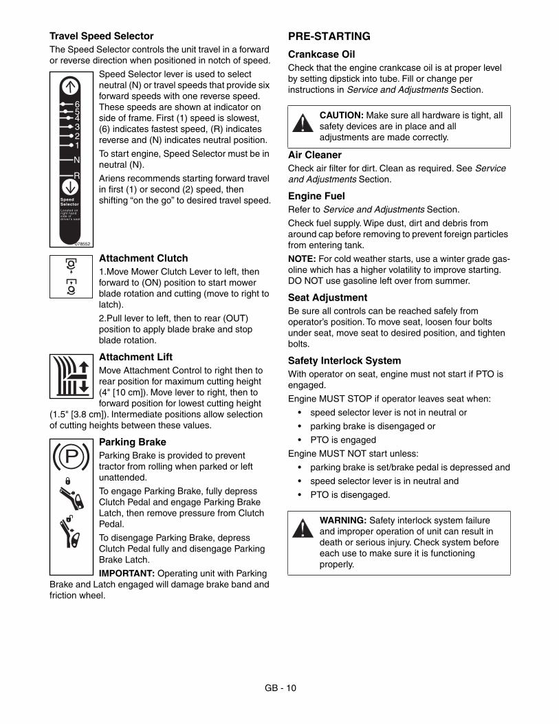
Travel Speed Selector
The Speed Selector controls the unit travel in a forward or reverse direction when positioned in notch of speed.
Speed Selector lever is used to select neutral (N) or travel speeds that provide six forward speeds with one reverse speed. These speeds are shown at indicator on side of frame. First (1) speed is slowest, (6) indicates fastest speed, (R) indicates reverse and (N) indicates neutral position.
To start engine, Speed Selector must be in neutral (N).
Ariens recommends starting forward travel in first (1) or second (2) speed, then shifting “on the go” to desired travel speed.
Attachment Clutch
1.Move Mower Clutch Lever to left, then forward to (ON) position to start mower blade rotation and cutting (move to right to latch).
2.Pull lever to left, then to rear (OUT) position to apply blade brake and stop blade rotation.
Attachment Lift
Move Attachment Control to right then to rear position for maximum cutting height (4" [10 cm]). Move lever to right, then to forward position for lowest cutting height
(1.5" [3.8 cm]). Intermediate positions allow selection of cutting heights between these values.
Parking Brake
Parking Brake is provided to prevent tractor from rolling when parked or left unattended.
To engage Parking Brake, fully depress Clutch Pedal and engage Parking Brake Latch, then remove pressure from Clutch Pedal.
To disengage Parking Brake, depress Clutch Pedal fully and disengage Parking Brake Latch.
IMPORTANT:
Operating unit with Parking Brake and Latch engaged will damage brake band and friction wheel.
PRE-STARTING
Crankcase Oil
Check that the engine crankcase oil is at proper level by setting dipstick into tube. Fill or change per instructions in Service and Adjustments Section.
Air CleanerCheck air filter for dirt. Clean as required. See Service and Adjustments Section.
Engine FuelRefer to Service and Adjustments Section.
Check fuel supply. Wipe dust, dirt and debris from around cap before removing to prevent foreign particles from entering tank.
NOTE: For cold weather starts, use a winter grade gas-oline which has a higher volatility to improve starting. DO NOT use gasoline left over from summer.
Seat AdjustmentBe sure all controls can be reached safely from operator’s position. To move seat, loosen four bolts under seat, move seat to desired position, and tighten bolts.
Safety Interlock SystemWith operator on seat, engine must not start if PTO is engaged.
Engine MUST STOP if operator leaves seat when:
• speed selector lever is not in neutral or
• parking brake is disengaged or
• PTO is engaged
Engine MUST NOT start unless:
• parking brake is set/brake pedal is depressed and
• speed selector lever is in neutral and
• PTO is disengaged.
078552
R
N
123456
SpeedSelectorLocated onr ight handside ofdr iver 's seat
P
CAUTION: Make sure all hardware is tight, all safety devices are in place and all adjustments are made correctly.
WARNING: Safety interlock system failure and improper operation of unit can result in death or serious injury. Check system before each use to make sure it is functioning properly.
GB - 11
STARTING AND SHUT OFF
Electric StartSee Figure 1 for all Controls and Features locations.
1. Place mower unit on level ground.
2. Place Speed Selector in neutral (N).
3. Place Mower Clutch Lever in disengaged (OUT) position.
4. Depress both Brake and Clutch Pedals to prevent rolling.
5. Insert key into ignition switch.
6. Set throttle to “Choke” position.
7. Turn key to “Start” position to crank engine and release when engine starts.
IMPORTANT: DO NOT operate starter motor more than 15 seconds per minute, as overheating and damage can occur.
8. Set throttle to Part Throttle or Slow position for adaptation to ambient temperature or transport. Once achieved, set throttle to Fast position for normal operation.
9. Select Speed Control range.
Manual Start1. Follow the previous starting steps 1-3.
2. Engage Parking Brake.
3. Turn key to Run position.
4. Set throttle to “Choke” position.
5. Grasp starter handle and pull rope out slowly until it pulls harder, this is compression stroke, let rope rewind slowly.
6. Pull rope with a rapid continuous full arm stroke. Let rope rewind slowly.
IMPORTANT: DO NOT let Starter Handle snap against Starter.
7. Repeat until engine starts. (If engine does not start, refer to Engine Manual).
8. Follow the previous starting steps 8-9.
STOPPING1. Depress clutch/brake pedal, disengage
Implement Power (lever OUT), lower attachment, fully depress clutch pedal and engage parking brake latch and then remove pressure from pedal.
2. Turn Ignition Key counterclockwise to stop engine.
3. Remove key.
PARKING
To park, stop the unit on level ground and engage the Parking Brake. Always take all possible precautions when leaving equipment unattended.
MOWING TIPSThe following tips will help you to mow safely, achieve maximum performance from your unit and maintain the desired appearance of the lawn.
NOTE: Clean mower pan after each use. DO NOT allow grass clumps or a coating of grass and debris to collect inside of mower pan. Avoid operation over bare ground intermittent with grass cutting as this causes dirt and grass to collect and cake under pan surface.
Grass should be cut when it is dry, not when it is wet from dew, rain or from watering. Wet grass tends to pack inside mower pan and will not discharge, mulch or bag properly, especially if height of cut is set low.
Keep mower blades sharp. Dull blades will tear grass and a white cast will result over a freshly cut lawn. The tips of the grass blades will then turn brown. A new lawn has soft blades of grass and a high moisture content.
Proper leveling and pitch of the rotary mower pan is needed for a smooth even lawn. If the pitch of the mower pan is in reverse or inadequate, grass will be cut twice, resulting in frayed grass ends. Too much pitch causes an uneven cut.
Upon first use of mower, cut the grass at a longer length. This will prevent scalping due to the irregularities in lawn.
To insure most complete and even cut, overlap each swath.
CAUTION: DO NOT attempt to start unit at this time. Read and understand entire manual before starting unit.
CAUTION: MACHINE ROLL AWAY can cause injury or death. ALWAYS engage parking brake when leaving unit unattended.
Stop engine, and remove key before cleaning or servicing unit.
WARNING: MOVING PARTS can cut or amputate body parts.
NEVER attempt to clear rotary mower pan or discharge while engine is running.
ALWAYS stop engine, remove key, and wait for moving parts to stop before clearing rotary mower.
CAUTION: Stay alert for holes, rocks, roots and hidden hazards in area of operation. Exercise extreme caution when operating on or crossing gravel surfaces. Stay alert for traffic.
GB - 12
Plan your cutting so that you always trim with the left side of the mower pan.
Following the same pattern each time you mow the lawn can develop ridges. Change direction in mowing pattern (when possible) to prevent ridges.
Generally, grass should be cut at about 1-1/2" (3.8 cm) long in the spring, and not less than 2" (5.1 cm) long in the hot summer weather.
Lower speed at turns to prevent scuffing.
If grass is high, or if it contains a high degree of moisture, cut it first with the mower pan set high. Cut the grass a second time, with the mower pan set lower, for a better distribution of clippings and a cleaner cut.
For thick, lush or heavy growth lawns do not set the cutting height too low. Grass cut too short may die.
When the blade is set too low, the mower pan will drag on the grass and restrict air flow, causing a reduction in the discharge of grass clippings.
Discharge grass clippings away from borderline objects (sidewalks, driveways, fences) when cutting grass. Discharge grass clippings over cut grass when not cutting borderlines. This will prevent a buildup of grass clippings on uncut grass area.
Adjust anti-scalp wheels properly for smooth appearance in cut.
Mow with engine set at full throttle to maintain proper blade speed and air flow for discharge of clippings.
Ariens Dealers will provide any service or adjustments which may be required to keep your unit operating at peak efficiency. Should engine service be required, contact an Ariens dealer or an authorized engine manufacturer's service center.
SERVICE POSITIONPlace unit on a flat level surface. ALWAYS stop engine and disengage clutches. Tip up on the service bar for ease of access during some procedures. Assure unit is secure and will not tip over. Strap and clamp onto lift if used.
IMPORTANT: When unit is tipped up onto its service bar, undrained gasoline drawn into cylinder may wash cylinder wall and shorten engine life.
FILLING FUEL TANK
To add fuel to Fuel Tank (figure 4):
1. ALWAYS place unit in open or well ventilated area.
2. Stop engine and allow to cool for 2 minutes.
3. Clean Fuel Cap and surrounding area to prevent dirt from entering Fuel Tank.
4. Remove Cap.
IMPORTANT: DO NOT use gasohol or gasoline containing alcohol. Alcohol will cause internal parts to deteriorate. See Engine Manual for correct type and grade of fuel.
5. Fill fuel tank to within 1/2" (1.3 cm) below bottom of filler neck with unleaded gasoline.
6. Replace Fuel Cap and tighten.
7. ALWAYS clean up any spilled fuel.
CAUTION: Grass catcher components are subject to wear, damage, and deterioration which could expose moving parts or allow objects to be thrown. Frequently check components and replace with manufacturer’s recommended parts when necessary.
SERVICE AND ADJUSTMENTS
WARNING: ACCIDENTAL ENGINE START UP can cause death or serious injury. ALWAYS stop engine, remove key, wait for moving parts to stop and remove wire from spark plug before adjusting or servicing.
HOT SURFACES can cause death or serious injury. DO NOT TOUCH parts which are hot from operation. ALWAYS allow parts to cool.
ROTATING PARTS can cut off body parts. Keep hands and feet away. Loose clothing, long hair or scarves can get caught in rotating parts and cause death or serious injury.
CAUTION: Remove enough fuel so that no spillage will occur. Remove battery to prevent spillage of electrolyte.
WARNING: FLAMMABLE FUEL and its EXPLOSIVE VAPORS can result in death or serious injury.
Handle fuel with care. ALWAYS use an approved fuel container.
No Smoking! No Lighted Materials!
No Open Flame!
Allow engine to cool before any service.
GB - 13
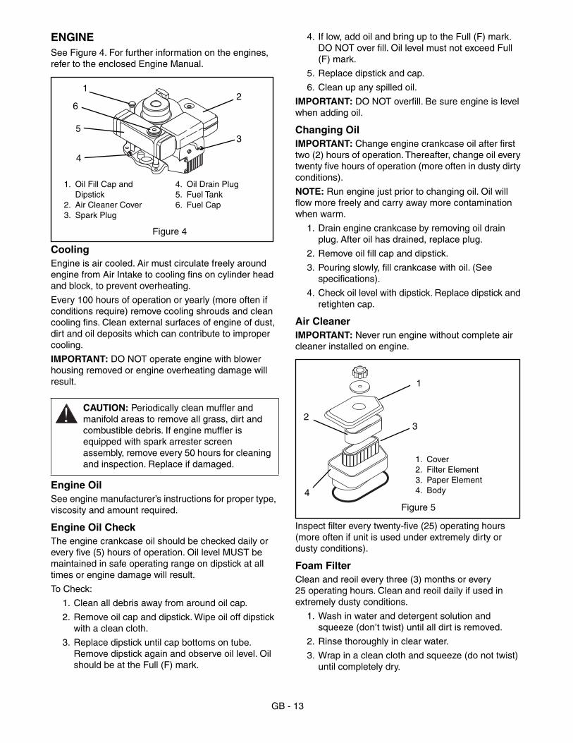
ENGINESee Figure 4. For further information on the engines, refer to the enclosed Engine Manual.
CoolingEngine is air cooled. Air must circulate freely around engine from Air Intake to cooling fins on cylinder head and block, to prevent overheating.
Every 100 hours of operation or yearly (more often if conditions require) remove cooling shrouds and clean cooling fins. Clean external surfaces of engine of dust, dirt and oil deposits which can contribute to improper cooling.
IMPORTANT: DO NOT operate engine with blower housing removed or engine overheating damage will result.
Engine OilSee engine manufacturer’s instructions for proper type, viscosity and amount required.
Engine Oil CheckThe engine crankcase oil should be checked daily or every five (5) hours of operation. Oil level MUST be maintained in safe operating range on dipstick at all times or engine damage will result.
To Check:
1. Clean all debris away from around oil cap.
2. Remove oil cap and dipstick. Wipe oil off dipstick with a clean cloth.
3. Replace dipstick until cap bottoms on tube. Remove dipstick again and observe oil level. Oil should be at the Full (F) mark.
4. If low, add oil and bring up to the Full (F) mark. DO NOT over fill. Oil level must not exceed Full (F) mark.
5. Replace dipstick and cap.
6. Clean up any spilled oil.
IMPORTANT: DO NOT overfill. Be sure engine is level when adding oil.
Changing OilIMPORTANT: Change engine crankcase oil after first two (2) hours of operation. Thereafter, change oil every twenty five hours of operation (more often in dusty dirty conditions).
NOTE: Run engine just prior to changing oil. Oil will flow more freely and carry away more contamination when warm.
1. Drain engine crankcase by removing oil drain plug. After oil has drained, replace plug.
2. Remove oil fill cap and dipstick.
3. Pouring slowly, fill crankcase with oil. (See specifications).
4. Check oil level with dipstick. Replace dipstick and retighten cap.
Air CleanerIMPORTANT: Never run engine without complete air cleaner installed on engine.
Inspect filter every twenty-five (25) operating hours (more often if unit is used under extremely dirty or dusty conditions).
Foam FilterClean and reoil every three (3) months or every 25 operating hours. Clean and reoil daily if used in extremely dusty conditions.
1. Wash in water and detergent solution and squeeze (don’t twist) until all dirt is removed.
2. Rinse thoroughly in clear water.
3. Wrap in a clean cloth and squeeze (do not twist) until completely dry.
CAUTION: Periodically clean muffler and manifold areas to remove all grass, dirt and combustible debris. If engine muffler is equipped with spark arrester screen assembly, remove every 50 hours for cleaning and inspection. Replace if damaged.
1. Oil Fill Cap and Dipstick
2. Air Cleaner Cover3. Spark Plug
4. Oil Drain Plug5. Fuel Tank6. Fuel Cap
Figure 4
21
6
3
4
5
1. Cover2. Filter Element3. Paper Element4. Body
Figure 5
1
32
4
GB - 14
4. Saturate with engine oil and squeeze (do not twist) to distribute oil and remove excess oil.
Paper FilterDo not attempt to clean or oil filter. Replace once a year or every 100 operating hours, more often if used in extremely dusty conditions.
Clean inside of cover and body of filter holder. Replace filter and cover and secure.
Spark PlugSpark plug should be cleaned or replaced (if necessary) and gap reset to .030" every 100 hours of operation or yearly whichever comes first.
To clean:
1. Remove debris from area around spark plug base.
2. Remove spark plug from engine.
3. Scrape and wash spark plug with a commercial solvent. DO NOT blast clean.
4. Replace spark plug.
NOTE: Sparking can occur if wire terminal does not fit firmly on spark plug. Replace terminal if damaged.
MufflerWorn out mufflers should be replaced immediately. Continued use could result in fire or explosion.
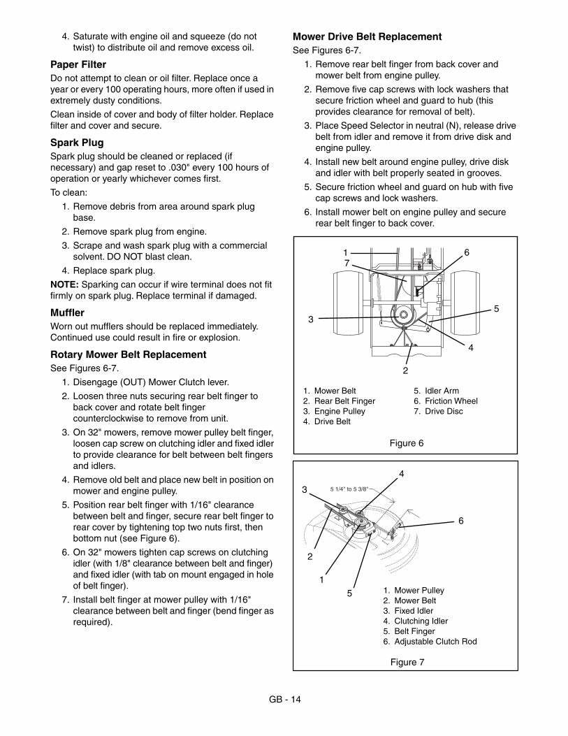
Rotary Mower Belt ReplacementSee Figures 6-7.
1. Disengage (OUT) Mower Clutch lever.
2. Loosen three nuts securing rear belt finger to back cover and rotate belt finger counterclockwise to remove from unit.
3. On 32" mowers, remove mower pulley belt finger, loosen cap screw on clutching idler and fixed idler to provide clearance for belt between belt fingers and idlers.
4. Remove old belt and place new belt in position on mower and engine pulley.
5. Position rear belt finger with 1/16" clearance between belt and finger, secure rear belt finger to rear cover by tightening top two nuts first, then bottom nut (see Figure 6).
6. On 32" mowers tighten cap screws on clutching idler (with 1/8" clearance between belt and finger) and fixed idler (with tab on mount engaged in hole of belt finger).
7. Install belt finger at mower pulley with 1/16" clearance between belt and finger (bend finger as required).
Mower Drive Belt ReplacementSee Figures 6-7.
1. Remove rear belt finger from back cover and mower belt from engine pulley.
2. Remove five cap screws with lock washers that secure friction wheel and guard to hub (this provides clearance for removal of belt).
3. Place Speed Selector in neutral (N), release drive belt from idler and remove it from drive disk and engine pulley.
4. Install new belt around engine pulley, drive disk and idler with belt properly seated in grooves.
5. Secure friction wheel and guard on hub with five cap screws and lock washers.
6. Install mower belt on engine pulley and secure rear belt finger to back cover.
1. Mower Belt2. Rear Belt Finger3. Engine Pulley4. Drive Belt
5. Idler Arm6. Friction Wheel7. Drive Disc
Figure 6
1
2
3
76
5
4
5 1/4" to 5 3/8"
1. Mower Pulley2. Mower Belt3. Fixed Idler4. Clutching Idler5. Belt Finger6. Adjustable Clutch Rod
Figure 7
4
3
6
5
1
2

GB - 15
MOWER BLADE
See figure 8.
Regularly check mower blades for wear and that lock washer is fully compressed by hardware.
28" and 32" decks: torque cap screw to 25-30 lbf-ft (34-47 N•m).
30" decks: torque nut to 50-60 lbf-ft (68-81 N•m).
When blade needs sharpening:
1. Block blade to prevent rotation.
2. Remove hardware and blade from shaft.
3. Sharpen the beveled edges of the blades in a straight line. Do not change the angle of the beveled edge.When blade becomes less than 2.00" wide, discard the blade. Make sure the sharpened blades are balanced. Balance must be held within 1.3 inch ounces.
4. Install blade, lock washer, and tighten hardware to torque listed above.
IMPORTANT: If mower is used under sandy soil conditions, replace blades when air lifts become eroded.
IMPORTANT: On 28" & 32", when replacing blade, blade should be 3/8" (9 mm) above flange. To position, turn cap screws on each end of blade tray until both tips of blade clear flange by 3/8" (9 mm) all the way around pan.
Mower Pan RemovalSee Figure 9.
1. Remove rear belt finger from back cover and mower belt from engine pulley (See Mower Belt section).
2. Position mower on flat level surface. Lower mower pan with Height Control lever. (Lowering mower pan down on blocks will relieve weight on linkage and make removal of pins easier).
3. Remove hair pin and rear hanger pin from swivel bracket to disconnect rear link.
4. Remove cotter pin from clutch rod and rod from clutch link.
5. Remove hair pin and front hanger pin to disconnect front linkage.
6. On 32" mower, remove hair pins and positioning arms from front mounting bracket.
7. Remove mower pan from rider.
8. Install mower pan on rider in reverse order.
BATTERYWhen Charging battery remove it from the unit first.
CAUTION: Replace bent, worn or damaged blades.
1. Cutting Edge2. Square Corner3. Air Lift Erosion
4. Air Lift5. Cap Screw6. Tip of Blade
Figure 8
12
3 4
5
6
WARNING: ELECTRIC SHOCK may result in injury and/or damage to unit.
DO NOT allow objects to come into contact with both terminals at the same time.
REVERSE CONNECTIONS may result in sparks which can cause death or serious injury. ALWAYS connect positive (+) lead of charger to positive (+) terminal, and negative (–) lead to negative (–) terminal.
ALWAYS connect positive (+) cable FIRST, and negative (–) cable SECOND.
1. Hairpin2. Front Hanger Pin3. Rear Links4. Swivel Bracket5. Rear Hanger Pin &
Hair Pin
6. Coupling Nut7. Jam Nut8. Upper Jam Nut9. Lower Jam Nut10. Lift Rod
Figure 9 OM0180
B. Rear Hanger
A. Front Hanger
1
2
3
4
5
76
9
8
10

GB - 16
Battery Electrolyte First AidFollow First Aid directions for contact with battery fluid.
• External Contact: Flush with water.• Eyes: Flush with water for at least 15 minutes and get
medical attention immediately!• Internal Contact: Drink large quantities of water.
Follow with Milk of Magnesia, beaten egg or vegetable oil. Get medical attention immediately!
IMPORTANT: In case of internal contact, DO NOT induce vomiting!
Cleaning Terminals
Keep battery and its terminals clean. Inspect monthly to maintain best performance.
Remove corrosion from battery terminals and cable connections with a wire brush, then wash with a weak baking soda solution.
After cleaning, apply a thin coat of grease or petroleum jelly to terminals and cable ends to retard corrosion.
Electrolyte LevelEvery 25 hours or each week check electrolyte level of each cell by removing caps one at a time. The electrolyte level should be at level indicator. Use distilled water to fill each cell if needed.
IMPORTANT: When distilled water is added to battery during freezing weather, it must be charged to mix water with electrolyte or water will remain at top and freeze.
ChargingALWAYS follow information provided on battery by battery manufacturer. Contact battery manufacturer for extensive instructions to charge battery.
Place unit on a level surface, shut off engine and open battery compartment to gain access to battery.
1. Disconnect negative (–) cable first, then positive (+) cable.
2. Loosen strap and remove battery.
3. Place Battery on bench or other well ventilated place where electrolyte spill will not create damage.
4. Remove caps and fill each cell to level indicated with electrolyte at 1.265±.05 specific gravity and 80°F (27°C).
5. Let battery stand for one half hour.
6. Check electrolyte level and add more if necessary.
7. Connect positive (+) lead of charger to positive (+) terminal, and negative (–) lead to negative (–) terminal.
8. Charge the battery at two and a half amps for ten hours or until all cells are gassing freely and the specific gravity is constant over three 30 minute intervals.
9. Immediately after charging, check electrolyte level. If low, add distilled water to bring cell up to required level.
10. Replace caps finger tight, wash off and dry battery.
11. Reinstall battery into unit and connect positive (+) cable first, then negative (–) cable.
Battery ChargerUnder normal conditions the engine alternator will have no problem keeping battery charged. When unit has set for an extended period of time without operation and the battery has been completely discharged, a battery charger will be required for recharging.
Before using a charger, an attempt can be made to recharge the battery using the engine alternator by jump starting the unit and allowing the to engine run.
JUMP STARTINGJump starting, battery charging or replacement is required when the starter motor will not crank the engine.
To jump start battery:
1. Ensure battery is not frozen. If the fluid is frozen, remove battery from unit and allow it to thaw before charging.
2. The unit used for jump starting should have a 12 volt battery with at least 500 cold cranking amperes, and a negatively grounded system.
WARNING: EXPLOSIVE GASES from battery can cause death or serious injury. ALWAYS keep open flames, sparks, or smoking materials away from batteries.
POISONOUS BATTERY FLUID contains sulfuric acid and its contact with skin, eyes or clothing can cause severe chemical burns. ALWAYS wear safety glasses and protective gear near battery.
DO NOT TIP any battery beyond 45° angle in any direction.
ALWAYS KEEP BATTERIES OUT OF REACH of children.
WARNING: Battery posts, terminals and related accessories contain lead and lead compounds, chemicals known to the State of California to cause cancer and reproductive harm. Wash hands after handling.
CAUTION: FROZEN BATTERIES CAN EXPLODE and result in death or serious injury.
DO NOT charge a frozen battery. Let the battery thaw out before putting on a charger.

GB - 17
3. Connect the positive (+) jumper cable to the positive terminal of the discharged battery.
4. Connect the other end of the same jumper cable to the positive (+) terminal of the booster battery.
5. Connect one end of the second jumper cable to the negative (–) terminal of the booster battery.
6. Make the final jumper cable connection to the engine block or the furthest ground point away from the discharged battery.
7. Follow steps in “Starting and Shut OFF”.
8. Remove jumper cables in the reverse order of their connection: Remove cable from ground point, the negative (–) terminal of the booster battery, the positive (+) terminal of the booster battery, and then the positive (+) terminal of the discharged battery.
IMPORTANT: DO NOT fast charge. Charging at higher rate will damage or destroy battery.
TIRESNOTE: Keep tires properly inflated at all times. For proper tire inflation when working under various condi-tions, refer to chart below. Use a low pressure tire gauge for accurate pressure readings.
Check tire pressure at least once a month. Over inflation may cause operator discomfort and excessive tire tracks on lawns or soft surfaces, while under inflation causes short tire life.
NOTE: After checking and/or inflating, replace and tighten valve caps to prevent air loss.
SEATClean seat regularly, using a vinyl cleaner (not solvent). Extreme temperatures can damage seat when left unprotected against weather. If seat should tear, apply vinyl repair tape to protect damaged area.
GENERAL LUBRICATIONIMPORTANT: Wipe each grease zerk fitting clean before and after lubrication. Keep grease and oil off belts to avoid slippage and deterioration.
Apply Sten Mix Hi-Temp Grease or equivalent to the lube fittings. Order P/N: 00036800 - three pack of 3 oz. cartridges or 00036700 - ten pack of 14 oz. cartridges.
Apply oil at lubrication points.
The steering system, front wheels, left rear wheel and linkage pivot points (figure 11) should be lubricated every 25 hours of operation, or twice each season, whichever occurs first.
WARNING: UNIT MOVEMENT can result in death or serious injury. NEVER jump start unit directly to the starter or starter solenoid. Unit can move forward or backward and injure the person jump starting unit.
CAUTION: REVERSE CONNECTIONS may result in sparks which may result in injury. ALWAYS connect/disconnect cables in proper order.
1. Battery2. Battery Cover3. Battery Strap
4. Positive Terminal (+)5. Negative Terminal (–)6. Filler Caps
Figure 10
1
3
2
5
6
4
Front 14 psi
Back 14 psi
GB - 18
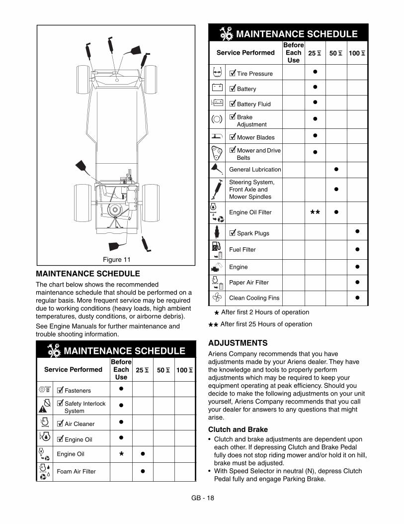
MAINTENANCE SCHEDULEThe chart below shows the recommended maintenance schedule that should be performed on a regular basis. More frequent service may be required due to working conditions (heavy loads, high ambient temperatures, dusty conditions, or airborne debris).
See Engine Manuals for further maintenance and trouble shooting information.
After first 2 Hours of operation
After first 25 Hours of operation
ADJUSTMENTSAriens Company recommends that you have adjustments made by your Ariens dealer. They have the knowledge and tools to properly perform adjustments which may be required to keep your equipment operating at peak efficiency. Should you decide to make the following adjustments on your unit yourself, Ariens Company recommends that you call your dealer for answers to any questions that might arise.
Clutch and Brake• Clutch and brake adjustments are dependent upon
each other. If depressing Clutch and Brake Pedal fully does not stop riding mower and/or hold it on hill, brake must be adjusted.
• With Speed Selector in neutral (N), depress Clutch Pedal fully and engage Parking Brake.
MAINTENANCE SCHEDULE
Service PerformedBefore Each Use
25 50 100
Fasteners •Safety Interlock System •Air Cleaner •Engine Oil •
Engine Oil •Foam Air Filter •
Figure 11
*
Service PerformedBefore Each Use
25 50 100
Tire Pressure •Battery •Battery Fluid •Brake Adjustment •Mower Blades •Mower and Drive Belts •
General Lubrication •Steering System, Front Axle and Mower Spindles
•
Engine Oil Filter •
Spark Plugs •Fuel Filter •Engine •Paper Air Filter •Clean Cooling Fins •
MAINTENANCE SCHEDULE
**
***
GB - 19
• Adjust double nuts on clutch rod until carrier yoke clears neutral stop by 1/8 to 1/4 inch (3–6 mm).
• Release Parking Brake and turn both rear wheels by hand. They should rotate freely in neutral (N) but not rotate with Speed Selector in any other position.
• Using two 1/2" wrenches (to avoid twisting or distorting brake band), hold inner adjusting nut with one wrench and loosen outer lock nut with the other.
• Turn rear wheel by hand while tightening inner adjustment nut until brake band just binds on hub. Back off adjusting nut by 1-1/2 turns and secure with locknut.
• Test by fully depressing Clutch Pedal and trying to turn wheels by hand. They should not turn.
Mower BeltAdjust mower belt after first five (5) hours of operation.
To adjust 28" and 30" mowers:
1. Place height control lever in midnotch position, depress spring clip and tighten yoke on front of unit with a 3/4" socket wrench (Figure 13).
2. When tightening cap screw, hold Mower Clutch lever so that front edge of lever is positioned in line with rear edge of forward notch of quadrant.
3. Tighten belt just enough to prevent slippage under load. Mower Clutch lever (when tightening cap screw) will move slightly to rear of this point when tension is correct.
To adjust the 32" mower:
1. The 32" mower belt clutch rod should be adjusted so the compressed spring length is from 5-1/4" to 5-3/8" (13.3–13.7 cm) when belt is engaged (See Figure 7 on page 14).
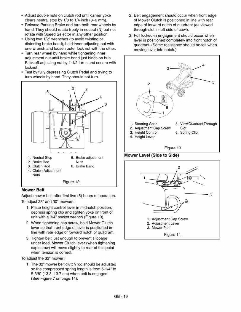
2. Belt engagement should occur when front edge of Mower Clutch is positioned in line with rear edge of forward notch of quadrant (as viewed through slot in left side of cowl).
3. Full locked-in engagement should occur when lever is positioned completely into front notch of quadrant. (Some resistance should be felt when moving lever into notch.)
Mower Level (Side to Side)1. Neutral Stop2. Brake Rod3. Clutch Rod4. Clutch Adjustment
Nuts
5. Brake adjustment Nuts
6. Brake Band
Figure 12
12 3
6
45
1. Steering Gear2. Adjustment Cap Screw3. Height Control4. Height Lever
5. View Quadrant Through Slot
6. Spring Clip
Figure 13
1
2
34
5
6
1. Adjustment Cap Screw2. Adjustment Lever3. Mower Pan
Figure 14
1
2
3

GB - 20
NOTE: A wood block (about 1" square by 5" long) may be used under pan for blade measurement. Wrap block with masking tape, mark tape with cutting edge of blade and measure distance from end of block to mark(s). This method avoids errors by having to read any measurements under pan.
NOTE: These adjustments should be made on a level surface with the tires inflated to the correct air pres-sure.
Cutting height range is 1.5" to 4.25" (3.8 –10.8 cm). Place Tractor on a smooth, flat, level surface. Do the following:
1. With blade(s) positioned side to side, measure distance of blade(s) tips to floor at right and left side of mower pan.
2. Rotate blade(s) 180° and check again. The measurement should be equal within 1/8" side to side.
To correct for difference in height of blade tips from side to side,
1. Loosen nuts on adjustment levers (Figure 14).
2. Turn adjustment cap screw clockwise on low side of mower pan to raise low side one half the difference in height.
3. Turn adjustment cap screw counterclockwise on high side to lower high side the other one half of the height difference.
4. Tighten nuts on adjustment levers.
Mower Pitch and HeightProper blade pitch is when the blade tip, measured from the bottom surface (Figure 16), is 1/4" to 3/8" (6–9 mm) lower at front of mower pan than when same tip is at rear of mower pan.
Adjusting front lift link raises or lowers front of mower pan and changes both cutting height and pitch (Figure 9).
To adjust:
1. Loosen jam nut on front link to allow for movement of coupling nut.
2. Turn coupling nut clockwise to raise and counterclockwise to lower front of mower pan.
3. Secure coupling in position by tightening jam nut.
Adjusting rear lift links raises or lowers rear of mower pan and changes both cutting height and pitch (Figure 9).
To adjust:
1. Loosen both lower jam nuts to allow for movement of upper jam nuts on lift rods.
2. Turn both upper jam nuts on each lift rod equally to raise or lower rear of pan.
3. Secure lift rods in position by tightening lower jam nuts.
If proper pitch cannot be obtained with front and rear lift links:
1. Loosen nut on carriage bolt and remove cap screw holding lift strap and adjustment strap together (Figure 17).
2. Slide lift strap and adjustment strap together to raise, or apart to lower rear of pan.
3. Select tapped hole in lift strap that provides proper adjustment, install cap screw in tapped hole and tighten nut on carriage bolt to secure.
CAUTION: Rotate mower blade with Mower Clutch disengaged (OUT) and take measurements with Mower Clutch engaged (ON).
1 2
OT0860
1. Cutting Tip2. Mower Pan3. Blade
4. Ground Level5. Cutting Height6. Discharge Chute
6
3 4
5
Figure 15
Figure 16
2
OT0130
1. Blade Cutting Edges2. Ground Level3. Front Blade Height4. Rear Blade Height
Front of Unit
1
34

GB - 21
Anti-Scalp RollersSee figure 1 for Controls and Features.
Secure rollers in middle position for average lawn mowing.
1. Use lowest roller position when mowing in higher cutting heights and rough terrain to guard against most scalping.
2. Use highest roller position when cutting at lowest cutting height.
For smoothest appearing cut when using frame suspended models with anti-scalp rollers, keep anti-scalp rollers adjusted to the minimum 1/2" (13 mm) above flat hard smooth surface after setting height of cut.
NOTE: The rollers are intended for anti-scalping, not for controlling cutting height.
IMPORTANT: DO NOT clean with a high pressure wash or store unit outdoors to aid in prevention of rust or corrosion. Water can seep into sealed bearings, which are sealed against dirt and debris only, causing reduced component life.
Keep all nuts, bolts and screws tight and know unit is in safe working condition. Check all hardware at regular intervals.
InspectionInspect unit for visible signs of wear, breakage or damage. Order any parts required and make necessary repairs to avoid delays when beginning use again.
Grass BagRemove Grass Bag and clean out all debris prior to storage. Grass Bag may be stored in position on mower. Keep Grass Bag dry during storage.
BatteryFully charge battery and store in a cool dry location.
EngineWhen storing mower for an extended period, refer to engine instruction for proper engine storage procedures.
CleaningUse a mild soap on a damp cloth to thoroughly clean unit of soil buildup. Touch up all areas to prevent rust. Matching touch up paint is available from your Ariens Dealer. Store mower in a cool, dry protected location.
Figure 17
1. Lift Strap2. Cap Screw - Remove to Adjust3. Carriage Bolt4. Adjustment Strap
12 3 4
STORAGE

GB - 22
TROUBLE SHOOTINGProblem Probable Cause
Starter will not operate when the ignition key is turned to the "S" position
Shift lever in gear (no spark).
PTO engaged.
Defective solenoid switch.
Blown Fuse.
Discharged battery.
Loose battery cables.
Defective starter.
Faulty interlock switch.
Solenoid switch clicks but starter will not operate when the ignition is turned to the “S” position.
Discharged battery.
Defective starter.
Loose battery cable.
Engine starter operates but engine will not start when the ignition switch is turned to the “S” position.
Fuel tank empty.
Fuel shut-off valve at the fuel tank turned off.
Engine failure - See Engine Manual.
Shift lever in gear (no spark).
PTO engaged (no spark).
Engine starts but runs roughly.
Engine choke in “ON” position.
Restricted air cleaner element.
Restricted fuel cap vent.
Engine carburetor malfunction - See Engine Manual.
Engine electrical system trouble - See Engine Manual.
Engine stops when PTO or Fwd-Rev is engaged.
Operator presence seat switch not pressed.
Faulty seat switch.
Wiring to PTO switch incorrect.
The tractor will not move when the direction control lever or pedal is moved to “FORWARD” or “REVERSE” position.
Gear shift lever in “NEUTRAL” position.
Fwd-Rev clutch needs adjustment.
Transmission disconnect is in the disengaged position.
Attachment will not operate.
PTO belt is off.
SERVICE PARTSPart No. Qty. Description
02749400 1 Battery
07216900 1 PTO Belt (Engine to 28”, 30” Decks)
07215500 1 PTO Belt (Engine to 32” Deck)
07211200 1 Transmission Belt
00300300 1 Friction Disk
02749300 1 Blade 28”
02728700 1 Blade 30”
02747000 1 Blade 32”
ATTACHMENTS82702000 2 Bucket Bagger 26"/30" Mowers
82702600 2 Bucket Bagger 28"/32" Mowers
ACCESSORIESSee your authorized dealer to add the additional accessories available for your unit.
70398500 Tire Chains
72701300 Dethatcher
72701600 Front Weight
72703400 Leaf Mulcher 30"
72703500 28" Mulching Kit
72703600 32"Mulching Kit

GB - 23
SPECIFICATIONSModel Number 927046 927055 927056
Description RM1028 RM1332 RM1330
Length - cm (in) 159 (62.5)
Height - cm (in) 99 (39)
Width - cm (in) 89 (35) 99 (39) 104 (41)
Actual Weight - kg(lbs) 168 (370) 170 (375) 168 (370)
Battery 180 CCA
Brakes Drum
Steering Gear & Pinion
Turning Radius - cm (in.) 66 (26)
Max. Angle of Slope Operation Not to exceed 10°
Tire Size Front - cm (in.)Rear - cm (in)
4.10-3.50x4.0016x6.5x8.00
Engine Briggs & Stratton
HP 10 HP 13 HP
Starting System Electric
Fuel Tank Cap. (2.84L) 3 Qt.
Fuel Unleaded
Idle RPM 1800
Governed RPM 3250
Crank Case Cap. (1.66L) 56 Oz.
Air Cleaner Paper Element/Foam Precleaner
Engine Oil Type SAE 30
Spark Plug - mm (in.) 0,76 (0.30)
Transmission Sealed Case
Speed - Forward Max. MPH (km/hr)Reverse Max. MPH (km/hr)
1.6-5.5 (2.6-8.8)2.7 (4.3)
Transmission Lube 150 Grease
Drive Clutch Disc-O-Matic
Tire Pressure - FrontRear
1414
Lift System Manual
Power Take-off Manual
Mower Deck - Flex & Float Standard
High Performance Standard
Cutting Width - cm (in.) 71.1 (28) 81.3 (32) 76.2 (30)
Cutting Height - cm (in.) 3.8-10.8 (1.5-4.25)
Cut Increments - cm (in.) 1.27 (0.5)

GB - 24
2 Year Limited WarrantyAriens Company warrants to the original purchaser that consumer products manufacturedby Ariens Company will be free from defects in material and workmanship for a periodof two (2) years after the date of purchase, and will repair any defect in material orworkmanship, and repair or replace any defective part, subject to the conditions, limitationsand exclusions set forth herein.
The two year duration of this warranty applies only if the product is put to ordinary,reasonable, and usual personal, family, or household uses. If the product is put to anybusiness, commercial, or industrial use such as, but not limited to, commercial landscaping,mowing or snow removal services, or golf course or park maintenance, or agriculturalor farmstead use, then the duration of this warranty is ninety (90) days after the dateof purchase, or one (1) year after the date of purchase if the product is labeled as aProfessional/Commercial Product. If any product is rented or leased, then the durationof this warranty is ninety (90) days after the date of purchase.
Genuine Ariens service parts and accessories not purchased with the product coveredby this warranty, but which are later purchased and used with that product, are warrantedto be free from defects in material and workmanship for a period of ninety (90) daysafter date of purchase, and Ariens Company will repair or replace any such part oraccessory free of charge, except for labor, during that period.
Ariens Company655 West Ryan StreetP.O. Box 157Brillion, WI 54110-0157920-756-2141Fax 920-756-2407www.ariens.com
This warranty is subject to the following conditions, limitations, and exclusions:
This warranty is valid only if the following conditions aremet:
• The warranty registration card must be completed andreturned to Ariens Company.
• The purchaser must perform maintenance and minoradjustments explained in the owner’s manual.
• The purchaser must promptly notify Ariens Company or anauthorized Ariens service representative of the need forwarranty service.
This warranty is subject to the following limitations:• The purchaser must transport the product to and from the
place of warranty service.• Warranty service must be performed by an authorized Ariens
service representative. (To find an authorized Ariens servicerepresentative, contact Ariens Company at the number oraddress above.)
• Batteries are warranted only for a period of twelve (12)months after date of purchase, on a prorated basis. For thefirst ninety (90) days of the warranty period, a defectivebattery will be replaced free of charge. If the applicablewarranty period is more than 90 days, Ariens Company willcover the prorated cost of any defective battery, for up totwelve(12) months after the date of purchase.
The following items are not covered by this warranty:• Engines and engine accessories are covered only by the
warranty made by the engine manufacturer, and are notcovered by this warranty.
• If the product is equipped with a Peerless gearbox and/ortransmission, the gearbox and/or transmission are coveredonly by the warranty made by Peerless, and are not coveredby this warranty.
• If the product is equipped with a Hydro-Gear transmissionand/or Hydro-Gear drive components, the Hydro-Geartransmission and/or drive components are covered only bythe warranty made by Hydro-Gear, and are not covered bythis warranty.
• Parts that are not genuine Ariens service parts are notcovered by this warranty.
• Shoes, runners, scraper blades, shear bolts, string trimmerheight guide, mower blades, mower vanes, trimmer line,headlights, light bulbs, are not covered by this warranty.
• Any defect which is the result of misuse, alteration, improperassembly, improper adjustment, neglect, or accident, is notcovered by this warranty.
• Products which were not purchased in the United States,Puerto Rico, or Canada are not covered by this warranty. Inall other countries, contact place of purchase.
Form: ALW2-112701
DISCLAIMER OF FURTHER WARRANTYAriens Company makes no warranty, expressor implied, other than what is expressly madein this warranty. If the law of your state providesthat an implied warranty of merchantability, oran implied warranty of fitness for particularpurpose, or any other implied warranty, appliesto Ariens Company, then any such impliedwarranty is limited to the duration of thiswarranty. Some states do not allow limitationson how long an implied warranty lasts, so theabove limitation may not apply to you.
LIMITATION OF REMEDY AND DAMAGESAriens Company’s liability under this warranty, and under anyimplied warranty that may exist, is limited to repair of anydefect in workmanship, and repair or replacement of anydefective part. Ariens Company shall not be liable for incidental,special, or consequential damages (including lost profits).Some states do not allow the exclusion of incidental orconsequential damages, so the above limitation or exclusionmay not apply to you.
This warranty gives you specific legal rights, and you may also have other rightswhich vary from state to state.

Ariens Company655 West Ryan StreetP.O. Box 157Brillion, WI 54110-0157920-756-2141Fax 920-756-2407