implant fundamentals part 2: surgical … part ii of implant fundamentals, participants will learn...
TRANSCRIPT

1 CECredit
IMPLANT FUNDAMENTALS PART 2: Surgical Techniques for Implant Placement & Prosthetic Selection
A Peer Reviewed Publication by Hu-Friedy

22
SOLUTIONS OVERVIEWIMPLANT FUNDAMENTALS
Prof. Mauro Labanca
Private practice, Milan, Italy Consulting Professor of Anatomy, University of Brescia.
© 2016 by Hu-Friedy Mfg. Co., LLC
First EditionAll rights reserved. No part of this publication may be reproduced, stored in a retrieval system or transmitted in any form or by any means, electronic, mechanical, photocopying, recording or otherwise without written permission from the publisher.
Dr. Carlos Quinones
Associate Professor, Department of Surgical Sciences, Division of Periodontics, University of Puerto Rico School of Dental Medicine Private practice, San Juan, Puerto Rico.
Dr. Lee Silverstein
Associate Clinical Professor of Periodontics at the Georgia Health Sciences University, College of Dental MedicineKennestone PeriodonticsMarietta, GA
SCIENTIFIC REVIEWERS
Dr. István Urbán
Associate Professor, Department of Periodontology, University of Szeged, HungaryPrivate practice, Budapest, Hungary
Hu-Friedy Mfg. Co., LLC is designated as an Approved PACE Program Provider by the Academy of General Dentistry. The formal continuing education programs of this program provider are accepted by the AGD for Fellowship, Mastership and membership maintenance credit. Approval does not imply acceptance by a state or provincial board of dentistry or AGD endorsement. The current term of approval extends from 6/1/2015 to 5/31/2019. Provider ID# 218966.

Abutment Typespage 16
Flap Designpage 5
ABSTRACTIn Part II of Implant Fundamentals, participants will learn different surgical techniques for implant site preparation and review considerations and importance of implant abutment options. Requirements and types of connection designs and abutment types will also covered.
OBJECTIVESAt the conclusion of Part II, participants will be able to:
• Understand the use and benefit of surgical templates
• List and describe flap designs and flapless surgery techniques
• List and describe implant placement techniques
• Understand prosthetic selection and requirements for implant/abutment connections
• Know the differences between fixed cement and screw retained restorations
COMMERCIAL DISCLAIMER
This education program is made possible through the continued support of Hu-Friedy Mfg. Co., L.L.C. The author(s) is a Hu-Friedy employee and/or consultant for different companies and organizations within the dental industry and received payment and/or product as compensation for the time involved in the development this course.
This course was written for dentists and dental professionals from novice to skilled.
Educational Methods: This course is a self-instructional journal and web activity.
Educational Disclaimer: Completing a single continuing education course does not provide enough information to result in the participant being an expert in the field related to the course topic. It is a combination of many educational courses and clinical experience that allows the participant to develop skills and expertise. Participants must always be aware of the hazards of using limited knowledge in integrating new techniques or procedures into their practice. Only sound evidence-based dentistry should be used in patient therapy.
Requirements for Successful Completion: To obtain 1 CE credit for this educational activity you must review the material, complete the course evaluation and obtain a score of at least 70% on the examination. Upon attaining a passing score, you will receive an emailed copy of your certificate of completion for 1 CE or you may print it immediately. This course is provided at no charge.

4
CHAPTER 1: SURGICAL TECHNIQUES FOR IMPLANT PLACEMENT
Implant surgery has evolved considerably since the original Branemark procedure and its delayed approach on the edentulous jaw (Branemark et al 1977). Not only have computers and digital treatment planning concepts been introduced to the field, but the implant components themselves have evolved and now feature innovative geometry, surface coatings (etched, blasted, coated, oxidized), and prosthetic connections that aid clinicians pursuing optimal outcomes—with less invasiveness—on behalf of their patients. Whereas Branemark defined separate surgical and prosthetic phases for his approach, dentists today can choose between two-stage, one-stage, and immediate implant placement techniques according to the conditions and needs of each patient.
The members of the interdisciplinary team must meet this increase in treatment flexibility with equal consideration. Working in concert with one another, they must determine the most appropriate protocol in terms of number of implants, flap design, and phases of implant treatment in order to achieve currently held criteria for success with dental implants (Albrektsson et al 1986; Smith/Zarb 1989).
THE SURGICAL TEMPLATE IS KEYA prefabricated surgical template is used to guide implant placement in the proper three-dimensional position according to the anatomic, prosthetic, and aesthetic requirements evident in the individual patient (Misch et al 2014; Singh, Cranin 2010; Arfai et al 2007).
• Single-tooth replacement between natural teeth: Teeth on either side of the implant site will stabilize the template, which is placed into position over the alveolar bone after flap reflection (Cranin 1999; Singh, Cranin 2010) (Figure 3.1).
• Free-end “saddle” edentulous areas: As for single teeth, but with the template extended anteriorly (4 teeth ideally) to the edentulous area and posteriorly past the anticipated distal extent of the incision line (Cranin: 1999; Singh, Cranin 2010) (Figure 3.2).
• Fully edentulous sites: A new denture should be fabricated at least to the wax try-in stage or converted from the patient’s existing removable denture, cutting away the lingual and occlusal aspects of the teeth to leave a “U-shaped trough” into which implant placement should be conducted (Cranin 1999; Singh, Cranin 2010).
Consisting of guiding cylinders and a contact surface (e.g., fitting the patient’s bone or teeth), the surgical template directs the implant drilling system and provides accurate placement of the implant(s) according to the surgical treatment plan. While the fabrication process associated with each is beyond the scope of the present discussion, it is important to know the “free-hand”, “milling”, and “computer-aided design / computer-assisted manufacturing” techniques are commonly used for preparing the guide holes according to the experience and preferences of the interdisciplinary team (Arfai, Kiat Amnuay 2007; Ramasamy et al 2013). The reliability and precision of these techniques are currently subjects of debate among learned practitioners, particularly in edentulous situations and flapless procedures.
Figure 3.1 Surgical guide applied at extraction site to guide implant positioning.
Figure 3.2 Computer-milled template showing guidance of implant drilling.

5
FLAP DESIGNIn the placement of dental implants, surgical flaps are generally elevated to permit better visualization of the bone ridge and reduce the potential of bone fenestration or perforation (Chrcanovic et al 2014). Flap procedures are designed to preserve and distribute keratinized tissue around the buccal, palatal, and interproximal areas (Anitua 1998).
Every surgical flap, regardless of the selected design, should always be as conservative as possible in order to promote optimal healing at the treatment site. At the same time, the design must provide the surgical team with a means of determining the morphology, size, and angulation of the alveolar bone.
Full-Thickness FlapsMucoperiosteal flaps, whether conducted on the buccal, lingual, or crestal aspect, are among the most common of designs and may or may not include vertical releasing incisions. When adjacent teeth are present, it is important to avoid the interproximal papillae in the flap design, as they can be virtually impossible to recover if damaged during the procedure (Figure 3.3). One must take steps to reduce surgical trauma to the tissues and to maximize their preservation wherever possible—including the techniques used for flap closure and stability. Additionally, the flap design needs to account for the blood supply, in order to prevent major damage of the vessels.
Partial-Thickness FlapsIn some instances, it is possible to take a more conservative approach to flap design (Figure 3.4). “Mini-flaps” are restricted to the area of implantation—such as a buccal flap for single-tooth replacement—and may reduce the potential of undesired scarring postsurgery (Ahmad 2012). Recent analysis in pigs (Lazic et al 2014) has suggested that a “mini incision,” compared to conventional flap surgery, provides better vascularization of the peri-implant mucosa after three months of healing. Similar histopathological analysis (Vlahovic et al 2014) confirms a decreased peri-implant inflammatory reaction as well. These investigations echo findings of previous investigators who have employed microsurgical techniques as means of reducing trauma at the site and promoting less tension in the closed tissues.
Tissue PunchThe tissue punch has been used for exposing the underlying bone in a “flapless” approach to implant placement (Salinas 1998). This approach has several specific requirements to use, including the presence of broad, flat ridges with adequate gingiva, no need for osseous contouring, and no need for GBR at the time of implant placement.
Figure 3.3 Diagram showing incorrect use of full-thickness flap, which includes the interproximal papillae in its design.
Figure 3.4 Diagram of a full-thickness flap, which protects the papillae during the surgical procedure.

6
Flapless SurgeryGiven that better visualization of the implant recipient site is inherent to flap design and elevation, any flapless method is essentially performed “blind” but is obviously the least invasive as well. When adequate volume of bone and attached gingiva are present (as determined via bone sounding, CT scan, panoramic radiographs, etc.), however, a flapless approach can be used. In such instances, a surgical template is imperative to precisely guide implant placement to the predetermined position three-dimensionally. The fixture head should be non-submerged, and a transmucosal healing abutment should be placed to sculpt the soft tissue to the proper contour (Ahmad 2012). Due to the inherent lack of visualization afforded to the operator and the potential for inadvertent perforation, a flapless approach should be attempted only by experienced clinicians (Anitua 1998).
TWO-STAGE IMPLANT PLACEMENTAlso known as the “submerged” or “delayed” approach, two-stage implant placement was the original Branemark procedure and advocated by this pioneer as a way of promoting stress-free integration of implants within the mandible (Branemark et al 1977). The implant was inserted in a first surgery (Figures 3.5 through 3.10), and submerged for three to six months to permit osseointegration. In a second surgical procedure, the implant was exposed, its cover screw removed, and the implant was then fitted with an abutment and the prosthetic phase of treatment was completed.
Figure 3.5 Case 1. Preoperative view of tooth #7 that will be replaced with an implant delivered in a two-stage approach.
Figure 3.7 Buccal view of the grafted maxillary lateral incisor site after six months.
Figure 3.6 Grafting and coverage of the extraction site with a barrier membrane, which is secured with a cross-mattress suture.
Figure 3.8 Implant placement in optimal position to support the definitive restoration.

7
The two-stage approach is sometimes uncomfortable for the patient but has a proven record of success over time (Adell et al 1981; Byrne 2010). It continues to be a valuable surgical option when primary stability cannot be achieved, or if extensive pre-surgical or concurrent bone augmentation is required. Research has shown, however, that osseointegration can also be achieved in a one-stage technique—provided bone of good quality exists—that simplifies and shortens treatment for the patient’s benefit (Hatano et al 2003; Byrne 2010; Esposito et al 2009; Garg et al 2011).
Figure 3.9A Preoperative x-ray shows lesion and moderate bone loss.
Figure 3.10 Three-month postoperative view of the single-unit implant restoration delivered via the staged approach.
Figure 3.9B Postoperative radiograph of definitive restoration.

8
ONE-STAGE IMPLANT PLACEMENTWhen aesthetics are not of concern, the cover screw or healing cap of the dental implant may be left exposed after the one-stage surgery, i.e., during osseointegration (Figures 3.11 through 3.14). After a suitable healing period, the cover screw is recovered—absent of a second surgical procedure. Based on extensive research, one-stage implant surgery has become a viable option for specific indications (Anitua 1998), though several prerequisites must guide proper patient selection for this approach:
• The patient must have bone quality (ideally type I or II) and quantity sufficient to ensure primary stabilization (the initial engagement between the bone and implant), i.e., no GBR required. The ISQ system is essential to confirm stability in this instance.
• An adequate circumferential zone of keratinized gingival tissue must be present.
• The abutment must precisely fit the implant.
• The abutment must be tightened to the proper torque value as dictated by the implant manufacturer. Torque values are measured in N/cm and are different for each dental implant system. Using the proper torque value is critical in order to prevent undue loosening.
• Abutment height must not compromise occlusion, and absolutely no contact or loading with the opposing dentition.
Figure 3.11 Case 2. Preoperative appearance of maxillary tooth #8 that will be replaced with a one-stage implant approach.
Figure 3.12 Two months following surgery, note the soft tissue response around the exposed healing abutment.
Figure 3.14 Facial view of the implant-supported crown and its integration with the adjacent natural teeth.
Figure 3.13 Postoperative radiograph of the implant-supported crown restoration on tooth #8.

9
Provided these criteria are addressed, this single-stage procedure permits early loading, is patient friendly, and is more economical than a two-stage approach (Ahmad 2012). Adequate oral hygiene counseling for the patient is also required to prevent and manage peri-implantitis and peri-mucositis, respectively.
IMMEDIATE POSTEXTRACTION IMPLANT PLACEMENTImplant placement following tooth extraction has also been advocated as a method of reducing treatment time, reducing the number of surgical protocols involved, and reducing the duration required for aesthetic rehabilitation (Huys 2001; Saadoun AP 2002; Saadoun AP 2004)—thus reducing costs for the patient as well. High survival rates have been reported in immediate implant placement, though bone resorption and gingival recession are complications that must be closely monitored to prevent tissue loss and/or exposure of the implant (Wohrle 1998; Schropp et al 2004). At present, indications for this approach include tooth fracture, radicular caries, and non-restorable crowns.
Bone augmentation, as noted previously, is often performed in conjunction with immediate implant placement due to the size discrepancy that exists between the extraction socket and dental implants (Chen et al 2004; Lang et al 2007) (Figures 3.15 through 3.20). Particulate grafts are used to maintain the necessary alveolar support at the site while simultaneously providing a scaffold for new bone growth.
Grasp and Stabilize Soft Tissue and Barrier Membranes During Suturing
Tissue pliers achieve superior grasp for enhanced tissue management during clinical procedures.
• Tungsten carbide inserts provide increased longevity
• Multiple designs accommodate clinician preference and different procedures
• Ideal for Guided Tissue Regeneration procedures
Figure 3.16 A sulcular incision separated the failing tooth from the periodontal tissue.
Figure 3.15 Case 3. Radiograph of horizontal root fracture apical to the alveolar crest.

10
Create Incisions WIth Periodontal Knives
Sharper instrument edges ensure precise incisions and efficient soft tissue recontouring
• End-cutting blades easily excise intrasulcular tissues
• Oval blades are ideal for initial gingivectomy incisions
SUMMARYThe goal of every treatment with dental implants, regardless of how the protocol is devised, is to create a functional and aesthetic outcome that is similar to that of the natural dentition. Importantly, fulfillment of this objective also ensures that the resorptive process of bone loss will be significantly reduced. Depending on the available bone present at the recipient site, the members of the treatment team have several options available for restoring the patient to an optimal result, and thorough communication among these individuals is critical for the best possible outcome.
Survival rates of >94.5% have been reported in the literature with this technique (Lang et al 2007; Schwartz-Arad et al 2007). Immediate postextraction implant placement affords the patient and interdisciplinary team alike the opportunity to undergo just a single surgical procedure, provides an immediate provisional restoration, and minimizes the potential for hard and soft tissue recession and concomitant loss of bone height and width. As such, it is a valuable part of contemporary implant dentistry and can be used to great effect.
Figure 3.18 Implant uncover at 6 months postsurgery permitted final impression making.
Figure 3.19 Postoperative radiograph demonstrates preservation of the alveolar bone housing.
Figure 3.20 Definitive implant restoration as delivered via immediate postextraction technique.
Figure 3.17 Implant placement in the curetted and debrided site; primary implant stability was achieved.

11
Adell R, Lekholm U, Rockler B, et al. A 15-year study of osseointegrated implants in the treatment of the edentulous jaw. Int J Oral Surg 1981;10:387-416.
Albrektsson T, Zarb GA, Worthington P, Erkisson AR. The long-term efficacy of currently used dental implants: A review and proposed criteria for success. Int J Maxillofac Impl 1986;1:11-25.
Anitua E. Implant Surgery and Prosthesis: A New Perspective. Evagraf, S. Coop Ltda., Vitoria, Spain, 1998. Translated by Lee, EA.
Arfai NK, Kiat-Amnuay S. Radiographic and surgical guide for placement of multiple implants. J Prosthet Dent 2007;97:310–312.
Brånemark PI, Hansson BO, Adell R, et al. Osseointegrated implants in the treatment of the edentulous jaw. Experience from a 10- year period. Scand J Plast Reconstr. 1977;16:1–132.
Byrne G. Outcomes of one-stage versus two-stage implant placement. J Am Dent Assoc 2010;141:1257-1258.
Chen ST, Wilson TG Jr, Hammerle CH. Immediate or early placement of implants following tooth extraction: Review of biologic basis, clinical procedures, and outcomes. Int J Oral Maxillofac Impl 2004;19:12–25.
Chrcanovic BR, Albrektsson T, Wennerberg A. Flapless versus conventional flapped dental implant surgery: A meta-analysis. Published online Jun 20, 2014. doi: 10.1371/journal.pone.0100624 PMCID: PMC4065043. Accessed August 26, 2014.
Cranin AN, Klein M, Simons A, eds. Atlas of Oral Implantology, 2nd ed. Mosby. 1999.
Esposito M, Grusovin MG, Chew YS, et al. One-stage versus two-stage implant placement. A Cochrane systematic review of randomised controlled clinical trials. Eur J Oral Implantol 2009;2(2):91-99.
Garg R, Borle RM, Datarkar AN. Clinical and radiological evaluation of two stage implant in a single stage procedure and two stage procedure—A comparative study. Archives Dental Res 2011;1(1):25-30.
Hatano N, Yamaguchi M, Suwa T, Watanabe K. A modified method of immediate loading using Branemark implants in edentulous mandibles. Odontology 2003;91(1):37-42.
Huys LW. Replacement therapy and the immediate post-extraction dental implant. Implant Dent.2001;10:93–102.
Lang NP, Tonetti MS, Suvan JE, et al. Immediate implant placement with transmucosal healing in areas of aesthetic priority: A multicentre randomized-controlled clinical trial I. Surgical outcomes. Clin Oral Implants Res 2007;18:188-196.
Lazi Z, Golubovi M, Markovi A, et al. Immunohistochemical analysis of blood vessels in peri-implant mucosa: A comparison between mini-incision flapless and flap surgeries in domestic pigs. Clin Oral Impl Res 00,2014, 1–5.
Manikandan Ramasamy G, Raja R, Subramonian, et al. Implant surgical guides: From the past to the present. J Pharm Bioallied Sc 2013;5(Suppl1):S98-S102.
Misch CE. Dental Implant Prosthetics. 2nd ed. St. Louis, MO: Elsevier, 2014.
REFERENCES

1212
REFERENCES
Saadoun AP. Immediate implant placement and temporization in extraction and healing sites. Compend Contin Educ Dent 2002;23:309–326.
Saadoun AP, Le Gall MG, Touati, B. Current trends in implantology: Part II—Treatment planning, aesthetic considerations, and tissue regeneration. Pract Proced Aesthet Dent 2004;16(10):707-714.
Salinas T. Soft tissue punch technique for aesthetic implant dentistry. Pract Periodont Aesthet Dent 1998;10(4):434.
Schwartz-Arad D, Laviv A, Levin L. Survival of immediately provisionalized dental implants placed immediately into fresh extraction sockets. J Periodontol 2007;78:219–33.
Schropp L, Isidor F, Kostopoulos L, et al. Patient experience of and satisfaction with, delayed-immediate vs. delayed single-tooth implant placement. Clin Oral Res 2004;15:498–503.
Singh P, Cranin N. Hard tissue surgery and bone grafting. In: Atlas of Oral Implantology, 3rd. Ed. Mosby, 2010.
Smith GD, Zarb GA. Criteria for success of osseointegrated endosseous implants. J Prosthet Dent 1989;62:567-572.
Vlahovic Z, Markovic A, Golubovic M, et al. Histopathological comparative analysis of peri-implant soft tissue response after dental implant placement with flap and flapless surgical technique. Experimental study in pigs. Clin Oral Impl Res 00, 2014, 1–6 doi:
Wohrle PS. Single-tooth replacement in the aesthetic zone with immediate provisionalization: Fourteen consecutive case reports. Pract Periodontics Aesthet Dent 1998;10:1107–1014.
Images presented with permission of the copyright holder and courtesy of Dr. Joseph Kan, Dr. Perry Klokkevold, Dr. Michael Klein, Dr. John Kois, and Dr. Adilson Torreao.

13
CHAPTER 2: PROSTHETIC SELECTION
Prosthetic considerations for the implant patient should dictate the surgical approach determined during treatment planning. As outlined in Part 1, it is the impression, bite registration, and diagnostic cast that allow the interdisciplinary treatment team to check occlusion, wax the intended result, and produce the master model that will enable fabrication of the radiographic stent and surgical stent that will guide implant placement. Consequently, the prosthetic outcome is the key consideration. Since there are various prosthetic options available, it is important to understand differences in abutment material composition, design characteristics, and suitability for implant rehabilitation.
The patient’s perception of the intended outcome is an important consideration in implant treatment and is closely connected to the provisionalization phase (Figures 4.1 to 4.3). After implant placement or guided bone regeneration, the surgical site must be protected from pressure or any loading in order to prevent bone loss or implant failure. While there are numerous techniques available for provisionalization, each must address the following requisites (Misch et al 2014):
• Provide patient comfort throughout the osseointegration period;
• Restore function to the patient;
• Achieve an aesthetic outcome, whether a single- or multiple-unit prosthesis;
• Protect the seated implant fixture or graft site from contact; and
• Maintain longevity, as healing may require six to nine months.
This section of the book presents considerations related to the selection of the implant/abutment connection, abutment design, laboratory communication, and screw versus cement retention concepts.
Figure 4.1 View of existing restoration (#9) that will be replaced due to mobility and carious lesion below the crown.
Figure 4.2 View of the provisional restoration in place immediately following implant insertion.
Figure 4.3 Postoperative view six months following cementation of definitive implant crown restoration.
14
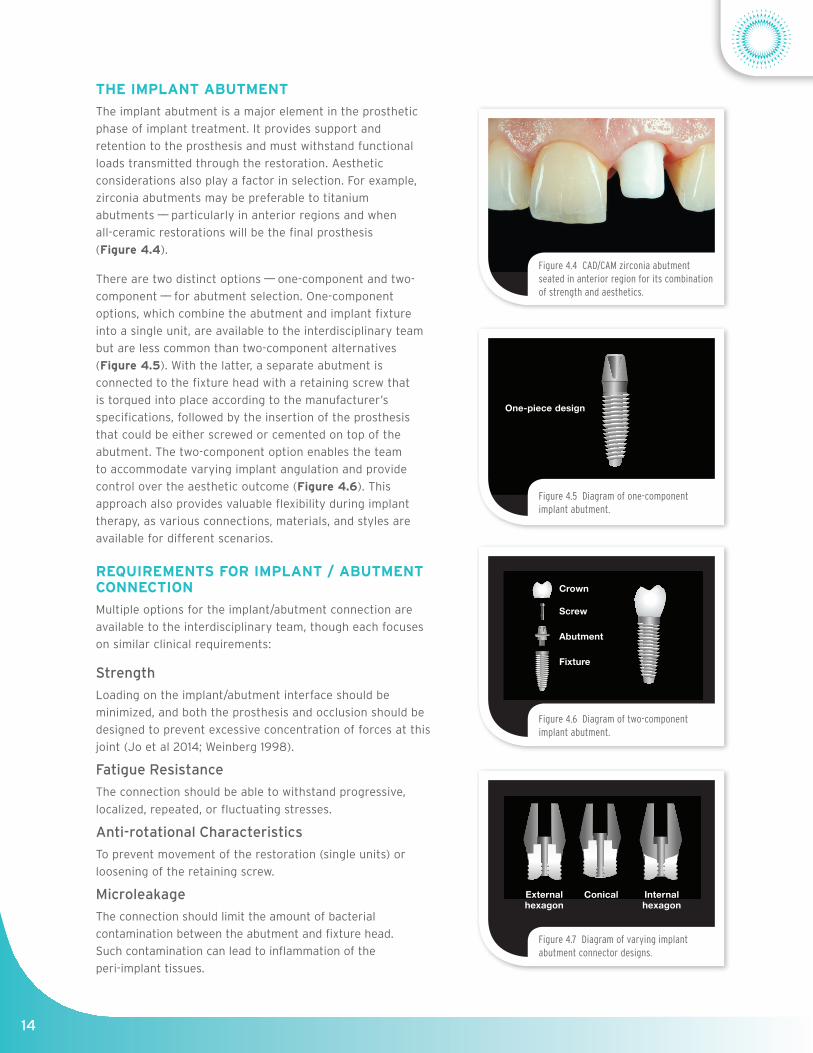
THE IMPLANT ABUTMENTThe implant abutment is a major element in the prosthetic phase of implant treatment. It provides support and retention to the prosthesis and must withstand functional loads transmitted through the restoration. Aesthetic considerations also play a factor in selection. For example, zirconia abutments may be preferable to titanium abutments —— particularly in anterior regions and when all-ceramic restorations will be the final prosthesis (Figure 4.4).
There are two distinct options —— one-component and two-component —— for abutment selection. One-component options, which combine the abutment and implant fixture into a single unit, are available to the interdisciplinary team but are less common than two-component alternatives (Figure 4.5). With the latter, a separate abutment is connected to the fixture head with a retaining screw that is torqued into place according to the manufacturer’s specifications, followed by the insertion of the prosthesis that could be either screwed or cemented on top of the abutment. The two-component option enables the team to accommodate varying implant angulation and provide control over the aesthetic outcome (Figure 4.6). This approach also provides valuable flexibility during implant therapy, as various connections, materials, and styles are available for different scenarios.
REQUIREMENTS FOR IMPLANT / ABUTMENT CONNECTION Multiple options for the implant/abutment connection are available to the interdisciplinary team, though each focuses on similar clinical requirements:
Strength Loading on the implant/abutment interface should be minimized, and both the prosthesis and occlusion should be designed to prevent excessive concentration of forces at this joint (Jo et al 2014; Weinberg 1998).
Fatigue ResistanceThe connection should be able to withstand progressive, localized, repeated, or fluctuating stresses.
Anti-rotational CharacteristicsTo prevent movement of the restoration (single units) or loosening of the retaining screw.
Microleakage The connection should limit the amount of bacterial contamination between the abutment and fixture head. Such contamination can lead to inflammation of the peri-implant tissues.
Figure 4.5 Diagram of one-component implant abutment.
Figure 4.6 Diagram of two-component implant abutment.
Figure 4.4 CAD/CAM zirconia abutment seated in anterior region for its combination of strength and aesthetics.
Figure 4.7 Diagram of varying implant abutment connector designs.
One-piece design
Crown
Screw
Abutment
Fixture
External hexagon
Conical Internal hexagon

15
CONNECTION DESIGNSMore than 20 different types of implant/abutment connections are currently available (Ahmad 2012; Binon and McHugh 1996). Their current designs include external and internal connections (Figure 4.7).
The external hexagon design was the original connection used by Branemark for supporting the metal substructure and prosthesis. This connection was 0.7mm in height and is more appropriate for use with multi-unit implant-supported prostheses, e.g., with a fixed partial denture (Ahmad 2012). Due to its height, this connection is less ideal for single-tooth implants as it is not suited for the intraoral forces directed to an individual implant.
The internal connection concept is derived from two basic designs —— the “butt joint” (two parallel flat connecting surfaces) and the internal “cone-in-cone” design (Ribeiro et al 2011). Internal connections are available with various seating depths (ranging from 1.2mm to 4mm) into the fixture, with different configurations including the conical (i.e., Morse taper), internal hexagon, and tri-corner (Figures 4.8 and 4.9). These configurations provide the anti-rotation characteristic to the prosthetic part.
Most research on the implant/abutment connection involves the external hexagon design, due in part to their tenure in the market, their extensive use, their range of clinical applications, and the level of complications reported (Binon 2000). With regard to internal connection designs, recent studies have suggested a potential mechanical advantage over butt-joint designs (Ribeiro et al 2011), though the type of connection has seemingly less influence on the stresses and strains transferred to the bone (Ahmad 2012).
ABUTMENT TYPES
Material ConsiderationsVarious materials, inclusive of plastic, gold, titanium, and ceramics, have been used to fabricate implant abutments. Plastic copings are generally used during provisionalization, as they provide an inexpensive interim solution while the implants osseointegrate. Customized, cast-gold abutments (such as UCLA abutments) continue to be popular in dentistry because of their contour and flexibility (i.e., in angulation). More recently, dental professionals have had the option too to select CAD/CAM abutments that can be made with excellent accuracy and efficiency (Park et al 2014).
The first CAD/CAM-fabricated abutments were made of alumina. Lately, titanium and zirconia abutments that are less prone to fracture and greater flexural strength have replaced alumina (Figures 4.10 and 4.11). Zirconia abutments are also valuable in anterior regions, providing the combination of machining precision, strength, and aesthetics. Additionally, epithelial tissues adhere well to titanium, alumina, or zirconia abutments (Figure 4.12) (Ahmad 2012), which makes each of these materials a viable alternative to silica or cast gold options.
Figure 4.9 Occlusal view of the tri-corner implant abutment connector design.
Figure 4.11 Zirconia abutment fabricated via CAD/CAM and featuring a concave emergence profile.
Figure 4.10 Titanium abutment, fabricated via CAD/CAM, is connected to the dental implant.
Figure 4.8 Occlusal view of implant abutment connector designs.
External hexagon
Conical Internal hexagon

16
Prefabricated vs. Customized AbutmentsPrefabricated or “stock” abutments are available in various shapes, heights, and angulations. Some of these abutments can be modified chairside to address requirements such as interocclusal clearance and implant position. Prefabricated abutments have also been utilized in platform switching protocols as a way of limiting marginal bone loss at the neck of the implant (Annibali et al 2012).
Cast-gold UCLA abutments, named for their origin at the University of California, Los Angeles, provide the interdisciplinary team with a customizable option to accommodate misaligned implants. The UCLA abutment can be customized by angle, taper, or finish line to achieve the necessary emergence profile for the definitive crown (Figure 4.13). CAD/CAM technology is the latest development in customizable abutments and enables their fabrication from titanium and ceramic materials (such as zirconia) to the precise specifications of the individual case. Although either titanium or zirconia can be used as a single “monoblock” abutment, only zirconia is available in multiple shades in order to achieve the desired aesthetic match to the adjacent dentition.
LABORATORY COMMUNICATIONIt is very important to accurately transfer intraoral data to the laboratory technician fabricating the definitive restoration. These data include the number of implants, their intraoral location, size, and angulation, and the position of the surrounding soft tissues. The position of the opposing dentition and adjacent teeth must also be conveyed (Figure 4.14). Tissue depth and type are also essential communication points for the interdisciplinary treatment team. Occlusal records and facebow records are integral to the communication process, but perhaps of greatest importance is the impression —— whether accomplished via conventional or digital means.
Polyvinylsiloxane (PVS) or polyether impressions are most commonly used for taking fixture-level impressions. The closed or open tray impression techniques are two methods used to take fixture-level impressions utilizing impression copings made of plastic, titanium, or aluminum. If the angle of the implant will hinder the withdrawal of the tray, then an open tray impression technique with PVS material is used to capture the position of the fixture (Figure 4.15). Once transferred to the dental laboratory, implant analogs are seated and connected to the copings, following, by pouring a stone model.
Figure 4.12 Illustration of the adherence that occurs around dental implants versus the attachment observed on natural teeth.
Figure 4.14 Facial view of the implant site as readied for conventional impression.
Figure 4.13 Angled stock abutments enable replication of diverse clinical requirements, such as the emergence profile of the central incisors.
Figure 4.15 Implant analog is inserted into post coping picked up in the impression.

17
The digital approach captures the position of the hard and soft tissues without elastomeric impression materials or the associated tray selection and material dispensing/setting. Digital impressions also eliminate disinfection and shipping processes for conventional approaches and may provide greater patient comfort as well (Papaspryridakos et al 2014). Each method must convey pertinent data to the laboratory regarding implant position, angulation, emergence profile, and intraoral structures necessary to design and mill the required implant restorative components (Figure 4.16).
FIXED CEMENT- AND SCREW-RETAINED RESTORATIONSEither cement or screw retention can be used for a single crown or multiple-unit implant restoration, and Tables 4.1 and 4.2 provide several guidelines as to their selection for a given implant case. Choosing between these alternatives is largely a matter of preference, as the research currently available shows little difference between them in terms of gingival health, peri-implant inflammation, marginal bone loss, or implant survival.
Figure 4.16 Digital impressions provide an efficient and accurate means of transferring clinical data to the dental laboratory.
TABLE 4.1EVALUATING CEMENT-RETAINED RESTORATIONS
Indications Limitations
Single-unit crowns, particularly in the aesthetic zone, and for severely misaligned implants
Situations (e.g., loosening) that require access to the abutment-retaining screw
Patients with thin biotypes Situations with deep (>3mm) subgingival margins
Where screw access holes are undesired Situations with limited interocclusal space
TABLE 4.2EVALUATING SCREW-RETAINED RESTORATIONS
Indications Limitations
Combination of crown/FPD and abutment provides greater strength and stability
The implant head requires vertical orientation based on anterior/ posterior usage
Retrievability, particularly for posterior single units and full-arch fixed restorations
Screw access hole must be masked or properly concealed from view
Limited interocclusal space Prone to gingival inflammation due to the position of the microgap relative to the gingival crest
TAKE THE POST TEST:www.Hu-Friedy.com/ImplantologyTest2

1818
REFERENCES
Ahmad I. Prosthodontics At A Glance. Wiley Blackwell, Oxford, UK. 2012.
Aniballi S, Bignozzi I, Cristalli MP, et al. Peri-implant marginal bone level: A systematic review and meta-analysis of studies comparing platform switching versus conventionally restored implants. J Clin Periodontol 2012;39(11):1097-1113.
Greenstein G, Cavallaro J, Romanos G, Tarnow D. Clinical recommendations for avoiding and managing surgical complications associated with implant dentistry: A review. J Perodontol 2008;79(8):1317-1329.
Binon PP. Implants and components: Entering the new millennium. Int J Maxillofac Implants 2000;15(1):76-94.
Binon PP, McHugh MJ. The effect of eliminating implant/abutment rotational misfit on screw joint stability. Int J Prosthodont 1996;9(6):511-519.
Javed F, Ahmed HB, Crespi R, Romanos G. Role of primary stability for successful osseointegration of dental implants: Factors of influence and evaluation. Interv Med Appl Sci 2013;5(4):162-167.
Jo JY, Yang DS, Huh JB, et al. Influence of abutment materials on the implant-abutment joint stability in internal conical connection type implant systems. J Adv Prosthodont 2014;6(6:491-497.
Misch CE. Dental Implant Prosthetics. 2nd ed. Elsevier, St. Louis, MO. 2015
Papaspryridakos P, Chen CJ, Gallucci GO, et al. Accuracy of implant impressions for partially and completely edentulous patients: A systematic review. J Oral Maxillofac Implants 2014;29(4):836-845.
Park JM, Lee JB, Heo SJ, Park EJ. A comparative study of gold UCLA-type and CAD/CAM titanium implant abutments. J Adv Prosthodont 2014;6(1):46-52.
Ribeiro CG, Maia MLC, Scherrer SS, et al. Resistance of three implant-abutment interfaces to fatigue testing. J Appl Oral Sci 2011;19(4):413-420.
Weinberg LA. Reduction of implant loading with therapeutic biomechanics. Implant Dent 1998;7(4):277-285.
Figures courtesy of Giacomo Fabbri, Ramon Garcia-Adamez Soto, Bernard Touati, and Eric van Dooren. Special thanks to Justin Cruz, Kennesaw State University, Georgia, for assistance with the references cited herein.