implementation and testing of autonomous quad-rotor … · module is set inside the ardupilot which...
TRANSCRIPT
Abstract—In this article self-ruling autonomous quad-rotor,
(AQR) Unmanned Aerial Vehicle (UAV)" system is developed.
It has four rotors or engines and can fly without a pilot. The
controlling and the velocity calculations of the UAV is control of
diverse systems. The self - ruling UAV is accurately made to
keep up harmony between velocity, weight, sound and force. It
abides in four adjustable disperse arms with engines. Changes in
engine velocities are utilized to adjust the position in the desired
manner. All the association has been carried out in the middle of
the UAV. Module is set inside the Ardupilot which is utilized to
send signals to the engine with respect to the estimation of the
sensors like GPS (U-Box GPS v2. 0), Gyro, Accelerometer and
Barometer maintain a particular height. The venture is the
implicit request to make a suitable and programmed flight
starting in one direction, then in the next direction with defined
height and pace. It must be remembered that the procurement of
computations and investigation of the inertial measurement
system must be performed precisely. Basically, this UAV full fill
the needs of any clever gear, which is utilized to screen the
ranges which are not in human reach.
Index Terms—Unmanned aerial vehicle, gyroscope,
Ardu-Pilot.
I. INTRODUCTION
In the course of the most recent few years a rapid
development in the production and offers on remote control
airborne vehicles known as unmanned aerial vehicles (UAVs)
are being used in several typical missions such as, search and
rescue missions, surveillance, inspection, mapping, aerial
cinematography and law enforcement. Many robust control
schemes have been developed for the uncertain nonlinear
systems. Among these control schemes, the sliding mode
control, which has drawn researchers’ much attention, has
been a useful and efficient control technique for handling
systems with large uncertainties, time varying properties,
nonlinearities, and bounded external disturbances [1]-[4].
On the other hand, a conventional aircraft can travel faster,
further and higher than a rotary wing. In order to merge these
benefits on a single air vehicle, vertical takeoff, landing
VTOL aircraft with a fixed wing configuration has been taken
into consideration for over five decades by academicians and
the industry itself [5], [6].
The quad - rotor UAV is the main concern in this paper. It
has four arms and settled contribute propellers which are
Manuscript received October 30, 2015; revised January 13, 2016.
Rana Javed Masood, Wang Dao Bo, and Zain Anwar Ali are with
Nanjing University of Aeronautics and Astronautics, China (e-mail: [email protected]).
Suhaib Masroor is with Shanghai University, China.
Muhammad Shafiq Loya is with the Department of Electronic
Engineering, Sir Syed University of Engineering and Technology, Pakistan.
situated X or + setup with X. Being the favored design. In the
standard arrangement two propellers will turn in a clockwise
direction with the other two turning in an anticlockwise
course permitting to lift vertically, drift noticeable all around
and fly in an assigned heading [7]. The AQR is a basic
configuration with less moving parts and has quickly turned
into a most loved vehicle for remote control fans and is
generally being utilized as a viable Aerial photographic stage.
An extensive larger part of the AQR was initially
manufactured by specialists who comprehend the smoothness
of the vehicle [8], [9].
It includes four engines and four propellers connected to a
lightweight edge built of light wood, carbon fiber, or
fiberglass then interface it to a remote control transmitter
through a little control board fitted with a gyroscopic
adjustment framework. Carrying out tests, the design of
varieties of the AQR by utilizing distinct measures of arms
seen Tri- Hex-Octa.
II. SELECTION OF COMPONENT
A. Frame
The essential and prominent component of AQR is its
frame that supports engines and different hardware and
escapes them from the vibrations. It is really precise when
assembling.
1) The arm
Making of arm from materials like wood, Aluminum,
Stainless Steel or PVC pipes, but it must validate the quality at
the time of ruthless landings. The best weight of AQR frame is
about 195 to 260 grams.
2) Frame centre-plate
It holds the arm of an AQR and different sensors lie on it.
By utilization of glass fiber, wood ply, aluminum, or any
material sheet they are lighter in weight.
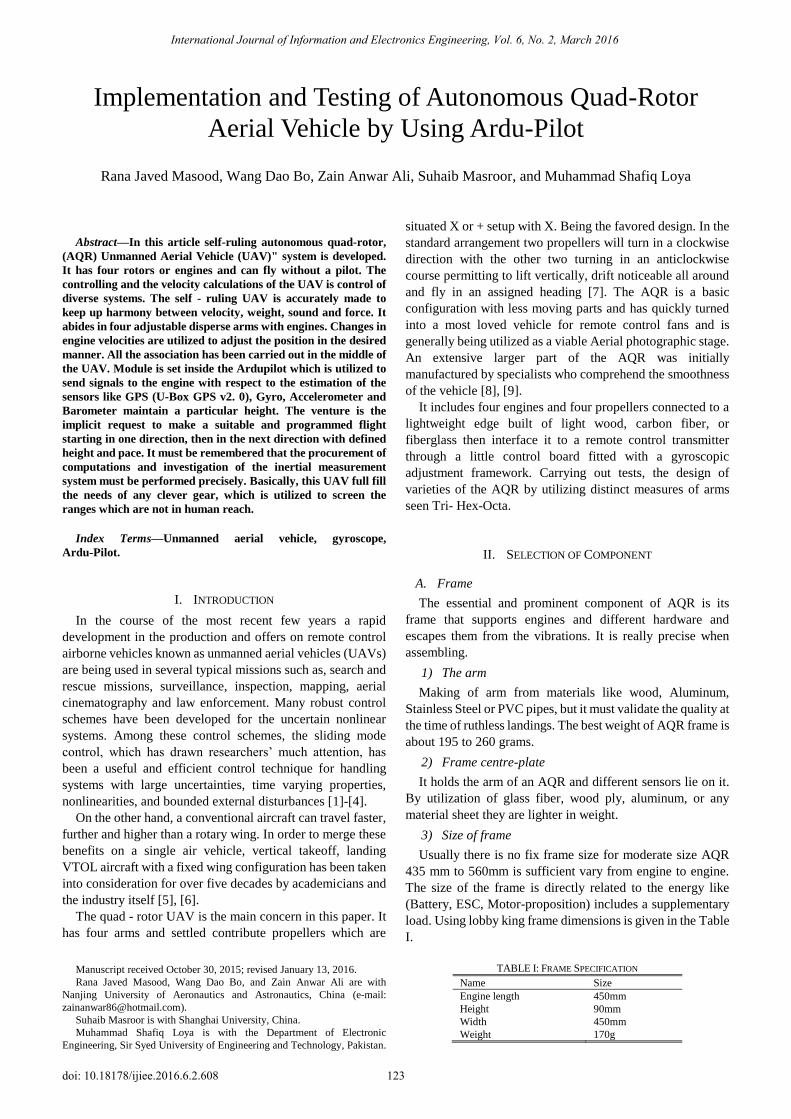
3) Size of frame
Usually there is no fix frame size for moderate size AQR
435 mm to 560mm is sufficient vary from engine to engine.
The size of the frame is directly related to the energy like
(Battery, ESC, Motor-proposition) includes a supplementary
load. Using lobby king frame dimensions is given in the Table
I.
TABLE I: FRAME SPECIFICATION
Name Size
Engine length 450mm
Height 90mm
Width 450mm
Weight 170g
Implementation and Testing of Autonomous Quad-Rotor
Aerial Vehicle by Using Ardu-Pilot
Rana Javed Masood, Wang Dao Bo, Zain Anwar Ali, Suhaib Masroor, and Muhammad Shafiq Loya
International Journal of Information and Electronics Engineering, Vol. 6, No. 2, March 2016
123doi: 10.18178/ijiee.2016.6.2.608

B. Engine
The crucial part of AQR is engine, representing a major
source of power consumption. In this research project we use
the brushless DC motor for AQR. 600 to 1200V rating engine
are suitable for AQR. The Table II represents a necessary
detail to choose the engine with respect to the required
specification.
TABLE II: MOTOR SPECIFICATIONS
Engine Essential Details For Best Results
KV 935
WEIGHT 55g
DIAMETER 27.9 mm
LENGTH 39 mm
BATTERY 3s (Li-PO) 10.45 Prop
MAXIMUM THRUST 850g
ESCRECOMMENDED
(For this Spec) 18A
To elevate or lift about 1000 to 1200 grams AQR will need
a cumulative thrust of about 2000 grams. AQR has four
engines and every engine is supposed to generate thrust as a
minimum as 500 grams to complete the requirement.
1) Propellers
Generally, ignore the piece of plastic in quad-rotor purpose
assurance of propellers is amazing. Information of propellers
is simple and they are spinning and pitch. The nature of the
prop is crucial as well as the contrast of dimension and pitch
on a flight of quad-rotor UAV. For the most part we see the
prop with the determination of 7, 3.5; 8, 4.5; 9, 5; 10, 3.8; 10,
4.5; 10, 6; 11, 4.7; 12, 3.8. (A span or Diameter in inches,
Pitch in inches. Diameter: The Virtual circle that prop
created).
Sum of movement / revolution seen over motor runs at
6660 RPM at no load. Anyway, after mounting the propellers
on it, RPM will be diminished. Now taking the sample of two
propellers 10, 3.8 and 10, 6. When the 10-inch measurement
propeller mounts, the Revolutions per Minute (RPM) of the
engine will be reduced to 3600 RPM. The foremost propeller
is about 3.6-inches of pitch that grip all interruptions so 60 ×
3.8 = 216 Inch/Sec for the trice leg, it has a 6-inch pitch 60 ×
6 = 360 Inch/Sec = 9.1 m/Sec [3].
In the event that 10, 3.8 prop our quad will move noticeable
all around at 5.7 meters/second, while by 10, 6 prop
Ascension rate will be increased to 9.1 meters/second. The
large diameter propeller can create more push/thrust (Table
III).
TABLE III: SYSTEM SPECIFICATIONS
SPECIFICATION’s
6 DOF Acc-Gyro MPU 6000
Barometer (Pressure Sensor)
Arduino Compatible
Open Source AP system
Atmel 's ATMEGA2560-16 au and ATMEGA32U
SPECIFICATION’s
6 DOF Acc-Gyro MPU 6000
Barometer (Pressure Sensor)
Arduino Compatible
Open Source AP system
Atmel 's ATMEGA2560-16 au and ATMEGA32U
2) Electronic speed controller
The electronic speed controller is used to provide the
constant power to the receiving side like servo-motor and the
controller of flight. It has the Battery Eliminated Circuit (BEC)
that requires only 5V. To choose better ESC for AQR, the
current rating must be greater than the power rating of the
motor.
3) The battery
Battery means power or fuel similar to a vehicle petrol tank.
A filled tank will drive the vehicle more. So if we use high
power rating battery in AQR it will fly more. Because AQR
has four engines and in every engine consume 15 Amp of
power, thus the total requirement is about 60 Amp. Where
“C” is the discharging rate of the battery. In this research
project we use 40C battery because if we use 25C the
calculation is about 2.2×25C = 55A that is not enough for our
AQR power that’s why we use 40C×2.2 = 88A which is useful
for our AQR.
4) The flight controller
There are many controller boards; some of them are K.K
Board, Multiwii Board, Naza Board. In this paper, we will
discuss about the features of Ardu Mega Pilot, its
specifications and modes.
III. MOVEMENT OF AUTONOMOUS QUAD-ROTOR VEHICLE
Fig. 1(a). Initial flight mode.
Fig. 1(b). Movement Flight mode.
An AQR acquired three Cartesian coordinates (X, Y, Z)
and 6-DOF via four control parameters. Dynamic inputs
referring (Col, Lat, Lon, Ped.) are altitude, lateral,
longitudinal and angular moments. (p, q, r), (u, v, w) and (θ, φ,
ψ) are the output of the vehicle and called as rotational
velocities, translational velocities and rotational angles.
Aerial robots exhibit a number of important physical effects
such as aerodynamic effects, inertial counter torques, the
gravity effect, gyroscopic effects and friction, etc. Due to
these effects, it is difficult to design a real-time control for
aerial robots. The UAV aerial robot is a highly nonlinear,
multivariable, strongly coupled and under an actuated system
International Journal of Information and Electronics Engineering, Vol. 6, No. 2, March 2016
124
since they have six degrees of freedom [4]. To organize the
strategy of nonlinear sequential control to drive 6-DOF model,
require rotational and translational subsystems. The
movement of pitch, yaw and roll are as follows. Backward
pitch, forward pitch, right roll, left roll, clockwise yaw,
anticlockwise yaw, ascend and descend (see Fig. 1).
IV. TUNING PARAMETERS
A. Pitch Tuning
Tuning the pitch and rate of roll gives most of the data.
Stabilize Roll / Pitch P converts into the pivot rate at the
desired point, which is then strengthened the rate of the
controller. The higher the value makes copter more accessible
to move/pitch, while a lower value makes it smoother. On the
off chance that set excessively high, the copter will waver on
the move and/or pitch pivot on the off chance that set
excessively low the copter will get to be drowsy to inputs.
B. Yaw Tuning
Same like roll and pitch if any one stabilize, the yaw or yaw
rate gets extremely higher and the AQR bearing or direction
waver. At this time, the AQR will not be able to keep up its
altitude.
C. Altitude Tuning
At the altitude hold tuning, the altitude “P” by utilizing and
changing the elevation error between the destination height
and the real height the maximum rate produced will make an
effort to keep up its elevation yet in the event that sets
excessively high prompts an erratic throttle reaction. The rate
of throttle does not require regular tuning or changes over the
drop rate, but require a trip into a desired speed fall and down.
The throttle accelerates the Proportional Integral Derivative
(PID) controller additionally changing the speed (i.e. The
contrast between the desired action and increasing its speed)
into an engine yield. The 1:2 proportional ratio of P and I is
twice the measuring of P has to be kept up of the event that
regulates these three parameters. These qualities have never
to be expanded yet for compelling the AQR may show signs
of improvement and its reaction by decreasing its P & I to
0.5:1.0 (see Fig. 2).
Fig. 2(a). Tuning parameters.
Fig. 2(b). Pitch, yaw and roll controlling.
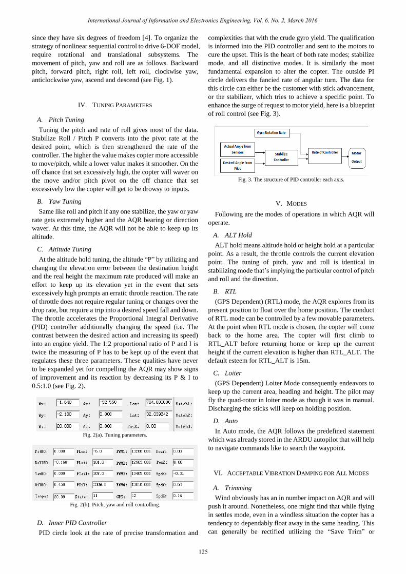
D. Inner PID Controller
PID circle look at the rate of precise transformation and
complexities that with the crude gyro yield. The qualification
is informed into the PID controller and sent to the motors to
cure the upset. This is the heart of both rate modes; stabilize
mode, and all distinctive modes. It is similarly the most
fundamental expansion to alter the copter. The outside PI
circle delivers the fancied rate of angular turn. The data for
this circle can either be the customer with stick advancement,
or the stabilizer, which tries to achieve a specific point. To
enhance the surge of request to motor yield, here is a blueprint
of roll control (see Fig. 3).
Fig. 3. The structure of PID controller each axis.
V. MODES
Following are the modes of operations in which AQR will
operate.
A. ALT Hold
ALT hold means altitude hold or height hold at a particular
point. As a result, the throttle controls the current elevation
point. The tuning of pitch, yaw and roll is identical in
stabilizing mode that’s implying the particular control of pitch
and roll and the direction.
B. RTL
(GPS Dependent) (RTL) mode, the AQR explores from its
present position to float over the home position. The conduct
of RTL mode can be controlled by a few movable parameters.
At the point when RTL mode is chosen, the copter will come
back to the home area. The copter will first climb to
RTL_ALT before returning home or keep up the current
height if the current elevation is higher than RTL_ALT. The
default esteem for RTL_ALT is 15m.
C. Loiter
(GPS Dependent) Loiter Mode consequently endeavors to
keep up the current area, heading and height. The pilot may
fly the quad-rotor in loiter mode as though it was in manual.
Discharging the sticks will keep on holding position.
D. Auto
In Auto mode, the AQR follows the predefined statement
which was already stored in the ARDU autopilot that will help
to navigate commands like to search the waypoint.
VI. ACCEPTABLE VIBRATION DAMPING FOR ALL MODES
A. Trimming
Wind obviously has an in number impact on AQR and will
push it around. Nonetheless, one might find that while flying
in settles mode, even in a windless situation the copter has a
tendency to dependably float away in the same heading. This
can generally be rectified utilizing the “Save Trim” or
International Journal of Information and Electronics Engineering, Vol. 6, No. 2, March 2016
125
“Programmed Trim” capacities (see Fig. 4).
B. Setting Throttle Mid
For checking the results of throttle mid position fly the
copter in a stable mode for at least 30seconds to check, If the
normal throttle is underneath 300 (i.e. 30%) then, one has an
exceptionally overwhelmed copter and it would be best to
include some additional weight (i.e. A greater battery maybe)
or diminishes the force in some other way (Smaller engines,
move from a 4S to a 3S battery, and so forth).
In the event that the normal throttle is over 700 (i.e. 70%)
then one has an exceptionally underpowered copter. One
ought to consider expanding the force of the engines and
ESCs or utilize a higher voltage battery (i.e. Switch from a 3S
to a 4S battery).
Fig. 4. Vibration range.
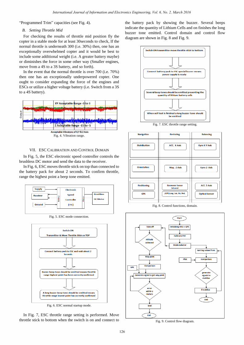
VII. ESC CALIBRATION AND CONTROL DOMAIN
In Fig. 5, the ESC electronic speed controller controls the
brushless DC motor and send the data to the receiver.
In Fig. 6, ESC moves throttle stick on top than connected to
the battery pack for about 2 seconds. To confirm throttle,
range the highest point a beep tone emitted.
Fig. 5. ESC mode connection.
Fig. 6. ESC normal startup mode.
In Fig. 7, ESC throttle range setting is performed. Move
throttle stick to bottom when the switch is on and connect to
the battery pack by showing the buzzer. Several beeps
indicate the quantity of Lithium Cells and on finishes the long
buzzer tone emitted. Control domain and control flow
diagram are shown in Fig. 8 and Fig. 9.
Fig. 7. ESC throttle range setting.
Fig. 8. Control functions, domain.
Fig. 9. Control flow diagram.
International Journal of Information and Electronics Engineering, Vol. 6, No. 2, March 2016
126
VIII. CONTROL FLOWCHART
Step A:
Plug in the battery, turn on the remote.
Step B:
Initialize IMU and GPS. Wait until the IMU’s (FC) and
GPS are ready, you can see the LED status from Blinking to
Stable state.
Step C:
Mode Selection
If Mode 0:
Step 1:
Getting the values from Gyro Accelerate and at the same
time we are getting the Pilot’s input.
Step 2:
Comparing both the values.
Step 3:
After comparing, signals generated to stabilize and go to
that desired location or state or position.
Step 4:
If Copter is stabilized and flying beautifully then ends the
command otherwise feedback the values of sensors to start the
process again.
If Mode 1:
Step 1:
Auto Mode Active
Take Off command active, in which we set the altitude
value (The vehicle will climb straight up from its current area
to the elevation determined (in meters). This ought to be the
first command of almost all missions. In the event that the
mission is started while the copter is flying, the vehicle will
climb straight up to the predetermined height, if the vehicle is
as of now over the predefined elevation the takeoff order will
be overlooked and the mission will move onto the following
summon instantly.)
Step 2:
If Altitude achieved.
Then move to step 3 otherwise repeat step 1.
Step 3 & 4:
Waypoint command
(The vehicle will fly a straight line to the area determined as
a lat, lon and height (in meters)) In this step we are comparing
the values of GPS, location and waypoint values, so it can
send signals to the Ardupilot where copter should move and in
which direction.
Step 5:
The GPS itself has 5~6-meter error, but it depends upon the
value of HDOP and no of satellites, in this step we calculate
the error between the desired locations. We make a circle
from the desired location if the error value lies in the circle,
then move to the next step which is Land command.
NOTE: You can also use the Delay command between
Takeoff, Waypoint & land commands.
IX. ESC CALIBRATION STEPS FOR ARDU-COPTER
1) Turn Transmitter ON and set Throttle to the maximum.
2) Associate the Li-PO battery. The Ardupilot's red, blue
and yellow LEDs will light up in a cyclical example.
This implies that prepared to go into ESC adjustment.
3) With the transmitter throttle stick still high, separate and
reconnect the battery
4) Hold up for ESCs to discharge the musical tone, the
customary number of beeps showing your battery's cell
check (i.e. 3 for 3S, 4 for 4S) and afterward an extra two
beeps to demonstrate that the greatest throttle has been
caught.
5) Now set Throttle to a minimum.
6) The ESCs ought to then discharge a long tone,
demonstrating that the minimum throttle has been caught
and the adjustment is finished.
7) In the event that the long tone, demonstrating fruitful
adjustment was listening, the ESCs is "live" now and on
the off chance that raise the throttle a bit they ought to
turn. Test that the engines turn by raising the throttle a bit
and afterward bringing down it once more.
8) Set the throttle to least and separate the battery to exit
ESC-adjustment mode.
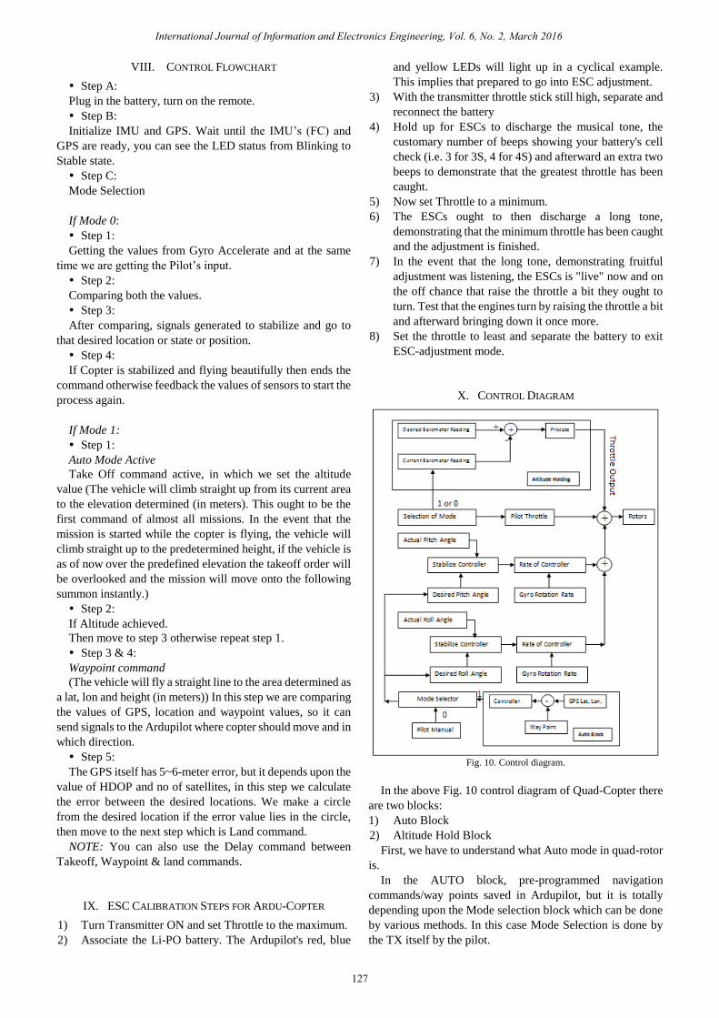
X. CONTROL DIAGRAM
Fig. 10. Control diagram.
In the above Fig. 10 control diagram of Quad-Copter there
are two blocks:
1) Auto Block
2) Altitude Hold Block
First, we have to understand what Auto mode in quad-rotor
is.
In the AUTO block, pre-programmed navigation
commands/way points saved in Ardupilot, but it is totally
depending upon the Mode selection block which can be done
by various methods. In this case Mode Selection is done by
the TX itself by the pilot.
International Journal of Information and Electronics Engineering, Vol. 6, No. 2, March 2016
127
After Arming the Copter it depends on the pilot if the pilot
wants to take a regular stabilize flight by himself, there will be
no signal transmitted through Mode Selection Channel, but if
he wants to make an autonomous flight, mode selection
channel is now High 1 or simply changed from the previous
state.
XI. AUTOMATIC INITIALIZING CONDITIONS
Initially the vehicle is in ground position and the controller
must assure the throttle is down, secondly, it will change into
an auto flight mode after that throttle elevates within a minute
the throttle is heaved more than zero the vehicle starts the
mission. From the beginning of the mission flight mode
switches on the auto mode. If the mission statement changes,
it sends the AQR above the impersonation instruction altitude
and the take-off call will be completed. The vehicle will be in
moving on the desired destination. When we want to control
the vehicle manually convert it into the flight mode and switch
it to alternate the flight mode like loiter or stabilize. Moreover,
when we shift it back on the auto mode again than the mission
statement will again restart from the initial charge.
Throughout the task manually move about throttle and pitch
inputs are ignored at that time yaw can be dominated with the
yaw stick. That will permit for the sudden point the head of
the vehicle has a camera on it as the vehicle flies on the
mission. The autopilot will undertake the yaw governed as the
AQR passes to the destination.
After selecting the mode and starting the mission Stabilize
and Rate PID (Desired Angle and Rotation Rate) starts doing
their magic to stabilize the copter and error rate.
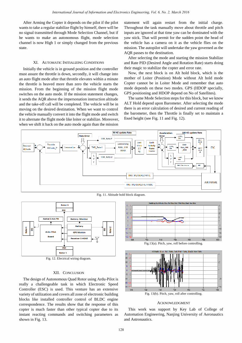
Now, the next block is on Alt hold block, which is the
mother of Loiter (Position) Mode without Alt hold mode
Copter cannot be in Loiter Mode and remember that auto
mode depends on these two modes. GPS (HDOP specially,
GPS positioning and HDOP depend on No of Satellites).
The same Mode Selection steps for this block, but we know
ALT Hold depend upon Barometer. After selecting the mode
there is an error calculation of desired and current reading of
the barometer, then the Throttle is finally set to maintain a
fixed height (see Fig. 11 and Fig. 12).
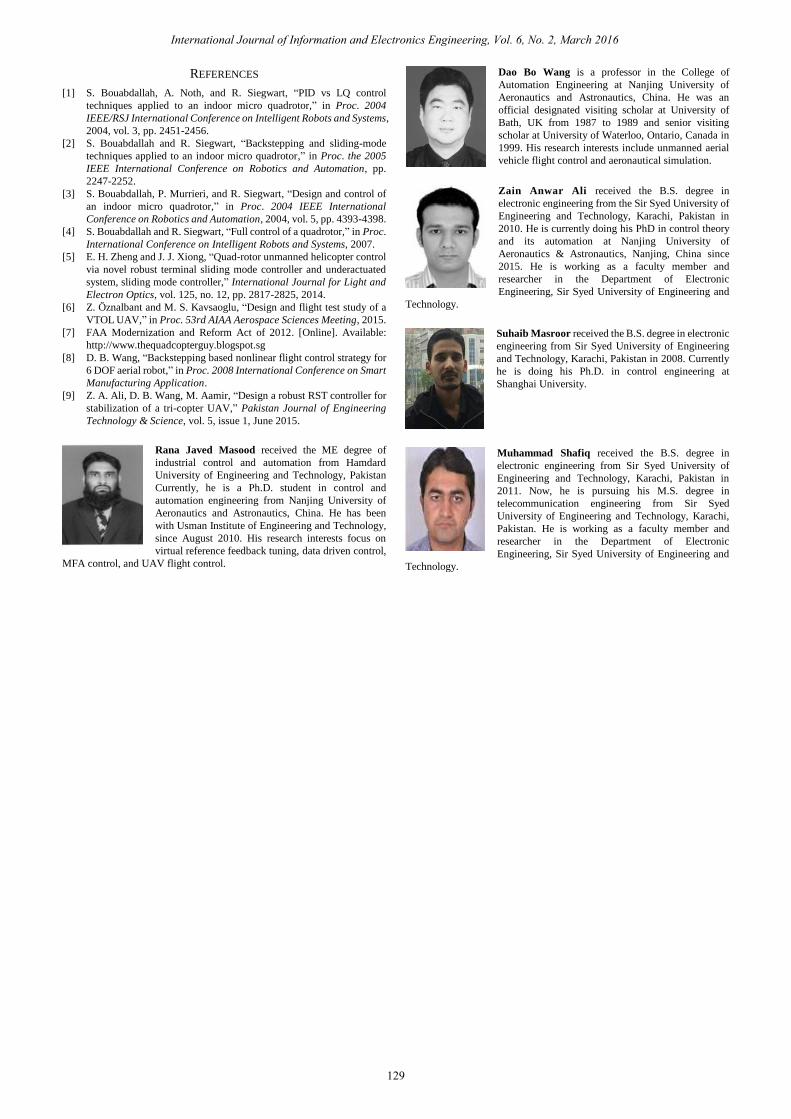
Fig. 11. Altitude hold block diagram.
Fig. 12. Electrical wiring diagram.
XII. CONCLUSION
The design of Autonomous Quad Rotor using Ardu-Pilot is
really a challengeable task in which Electronic Speed
Controller (ESC) is used. This venture has an extensive
variety of utilization and covers all zone of electronic building
blocks like installed controller control of BLDC engine
correspondence. The results show that the response of this
copter is much faster than other typical copter due to its
instant reacting commands and switching parameters as
shown in Fig. 13.
Fig.13(a). Pitch, yaw, roll before controlling.
Fig. 13(b). Pitch, yaw, roll after controlling.
ACKNOWLEDGMENT
This work was support by Key Lab of College of
Automation Engineering, Nanjing University of Aeronautics
and Astronautics.
International Journal of Information and Electronics Engineering, Vol. 6, No. 2, March 2016
128
REFERENCES
[1] S. Bouabdallah, A. Noth, and R. Siegwart, “PID vs LQ control
techniques applied to an indoor micro quadrotor,” in Proc. 2004
IEEE/RSJ International Conference on Intelligent Robots and Systems,
2004, vol. 3, pp. 2451-2456.
[2] S. Bouabdallah and R. Siegwart, “Backstepping and sliding-mode
techniques applied to an indoor micro quadrotor,” in Proc. the 2005
IEEE International Conference on Robotics and Automation, pp.
2247-2252.
[3] S. Bouabdallah, P. Murrieri, and R. Siegwart, “Design and control of
an indoor micro quadrotor,” in Proc. 2004 IEEE International
Conference on Robotics and Automation, 2004, vol. 5, pp. 4393-4398.
[4] S. Bouabdallah and R. Siegwart, “Full control of a quadrotor,” in Proc.
International Conference on Intelligent Robots and Systems, 2007.
[5] E. H. Zheng and J. J. Xiong, “Quad-rotor unmanned helicopter control
via novel robust terminal sliding mode controller and underactuated
system, sliding mode controller,” International Journal for Light and
Electron Optics, vol. 125, no. 12, pp. 2817-2825, 2014.
[6] Z. Öznalbant and M. S. Kavsaoglu, “Design and flight test study of a
VTOL UAV,” in Proc. 53rd AIAA Aerospace Sciences Meeting, 2015.
[7] FAA Modernization and Reform Act of 2012. [Online]. Available:
http://www.thequadcopterguy.blogspot.sg
[8] D. B. Wang, “Backstepping based nonlinear flight control strategy for
6 DOF aerial robot,” in Proc. 2008 International Conference on Smart
Manufacturing Application.
[9] Z. A. Ali, D. B. Wang, M. Aamir, “Design a robust RST controller for
stabilization of a tri-copter UAV,” Pakistan Journal of Engineering
Technology & Science, vol. 5, issue 1, June 2015.
Rana Javed Masood received the ME degree of
industrial control and automation from Hamdard
University of Engineering and Technology, Pakistan
Currently, he is a Ph.D. student in control and
automation engineering from Nanjing University of
Aeronautics and Astronautics, China. He has been
with Usman Institute of Engineering and Technology,
since August 2010. His research interests focus on
virtual reference feedback tuning, data driven control,
MFA control, and UAV flight control.
Dao Bo Wang is a professor in the College of
Automation Engineering at Nanjing University of
Aeronautics and Astronautics, China. He was an
official designated visiting scholar at University of
Bath, UK from 1987 to 1989 and senior visiting
scholar at University of Waterloo, Ontario, Canada in
1999. His research interests include unmanned aerial
vehicle flight control and aeronautical simulation.
Zain Anwar Ali received the B.S. degree in
electronic engineering from the Sir Syed University of
Engineering and Technology, Karachi, Pakistan in
2010. He is currently doing his PhD in control theory
and its automation at Nanjing University of
Aeronautics & Astronautics, Nanjing, China since
2015. He is working as a faculty member and
researcher in the Department of Electronic
Engineering, Sir Syed University of Engineering and
Technology.
Suhaib Masroor received the B.S. degree in electronic
engineering from Sir Syed University of Engineering
and Technology, Karachi, Pakistan in 2008. Currently
he is doing his Ph.D. in control engineering at
Shanghai University.
Muhammad Shafiq received the B.S. degree in
electronic engineering from Sir Syed University of
Engineering and Technology, Karachi, Pakistan in
2011. Now, he is pursuing his M.S. degree in
telecommunication engineering from Sir Syed
University of Engineering and Technology, Karachi,
Pakistan. He is working as a faculty member and
researcher in the Department of Electronic
Engineering, Sir Syed University of Engineering and
Technology.
International Journal of Information and Electronics Engineering, Vol. 6, No. 2, March 2016
129