implementation of advanced bim-based … of advanced bim-based mapping rules for automated...
TRANSCRIPT

IMPLEMENTATION OF ADVANCED BIM-BASED MAPPING RULES FOR AUTOMATED CONVERSIONS TO MODELICA
R. Wimmer1, J. Cao1, P. Remmen2, T. Maile1, J. O’Donnell3, J. Frisch1,
R. Streblow2, D. Müller2, C. van Treeck1
1RWTH Aachen University, Institute for Energy Efficient Building (E3D), Aachen, Germany 2RWTH Aachen University, E.ON Energy Research Center (EBC), Aachen, Germany
3School of Mechanical and Materials Engineering and Electricity Research Centre, University College Dublin, Dublin, Ireland
ABSTRACT
To address coming and forthcoming regulations for the reduction of energy use in the building sector, it is necessary to manage the complexity of buildings via flexible simulation tools. Modelica represents an object-oriented, equation-based programming language for detailed dynamic simulation purposes across different industries. This kind of simulation requires data at a high level of detail. Building Information Modelling (BIM) represents a data management tool for the whole life cycle of a building and can be used as input platform for simulation tools like Modelica, provided that tools for transformation of the 'BIM logic' into the logics of object oriented simulation exist. This paper is part of a project which aims to connect BIM with Modelica. During this course, the project defines mapping rules for integrating BIM within the process of Modelica code generation while supporting multiple modelling libraries with the purpose of developing an automated conversion process. This paper focuses on the consistency of the existing mapping rules and proposes various extensions by enabling an interface between BIM and different Modelica libraries.
INTRODUCTION The integration of simulation tools within a BIM-oriented planning environment is a promising approach to handle sophisticated projects (Eastman, 2011; van Treeck and Rank, 2007). For this purpose, the object-oriented, equation-based programming language Modelica offers a flexible structure to perform sophisticated Building Energy Performance Simulation (BEPS), especially when it comes to advanced energy systems. A solution to integrate multiple Modelica libraries via a single interface into the BIM environment – based on the rigidly defined data format IFC – does not yet exist in a generic way. The use of the Industry Foundation Classes (IFC) enables interoperability throughout the design process and provides information of the project for all experts (Building Smart Alliance, 2014).
Several studies analyse the integration of Modelica into a BIM-related environment. Jeong et al. (2014) developed a method to couple a BIM platform with Modelica by using the platform’s internal proprietary
data model. Furthermore, Hua (2014) developed a general approach of coupling IFC with Modelica. Each of these two different projects realises the connection by supporting a single Modelica library only, while IFC objects and attributes are mapped to the corresponding Modelica objects and parameters in a straightforward manner, representing a static connection between the two data sets. Consequently, this approach is sensitive to changes in the used Modelica library. Furthermore, the aforementioned research projects do not include any HVAC-systems, which represents the core interest of the research at hand.
In prior work, an approach to integrate Modelica into the BIM environment was developed by using the non-proprietary data exchange format SimModel (O'Donnell et al., 2011). SimModel aligns closely to IFC and is especially developed for the purpose of energy related simulations, focussing on the simulation of HVAC-systems. In this approach, so-called mapping rules are the basis for data conversion. For development purposes and as a first test, the mapping rules have been applied to a generic use case and a single Modelica library (Wimmer et al., 2014b; Cao et al., 2014).
The first implementation of the mapping rules acted as test to prove the concept. As a result, these rules provide the necessary functionality to connect SimModel to Modelica, but need further adjustments, referring to the definition of different rules. Furthermore, the mapping rules need to prove that this concept enables an interface between BIM and multiple Modelica libraries. The next steps consist of using different libraries with additional complex use cases. Thus, this paper describes the usage of the original six mapping rules by linking SimModel to several Modelica libraries and applies different use cases. These steps are necessary to improve the mapping rules and to enable a specialised interface between IFC and multiple Modelica libraries.
The paper describes as well the actors who need to provide expert knowledge to handle mapping rules. Two actors are relevant to apply the mapping rules: the first actor is responsible to provide his expertise in the SimModel data model, whereas the second actor knows the details of the targeted Modelica library and is responsible for the simulation.
Proceedings of BS2015: 14th Conference of International Building Performance Simulation Association, Hyderabad, India, Dec. 7-9, 2015.
- 419 -

The following section starts by describing the process to implement Modelica in the BIM environment generally. After the description of the process, we characterise the necessary actors for this process. The subsequent section presents improved mapping rules. The discussion section refers to limitations of this approach and the effort to enable a connection. Finally, the paper finishes with a conclusion of the presented approach and refers to future work.
PROCESS OF CONNECTING BIM WITH MODELICA The process to enable a link between a BIM platform and several Modelica libraries requires multiple steps and is illustrated in Figure 1.
Figure 1: Process from BIM to Modelica with the
corresponding actors and data models
Figure 1 depicts the process separated in five different steps. To handle the tool chain, several actors are involved and part of the process. The first step consists of creating a valid and well-formed IFC file. An architect is typically responsible for the overall design and the building envelope and an HVAC engineer takes care of the designing and dimensioning of the HVAC systems. The second step consists of the transformation of the IFC model into a SimModel representation. The third step consists of the enrichment of the SimModel data model to include all the necessary information as data basis for the simulation. An Energy-Consultant will then be responsible for the SimModel definition and the enrichment step of this process. The fourth step represents the transformation and data exchange of the SimModel data to a specific Modelica library, followed by the last step of modelling the simulation model by a so-called Simulation-Expert. The
Simulation-Expert knows details of the used Modelica library. As part of the international IEA-
EBC Annex 60 Project “Computational tools for building and community energy systems”, four libraries for building physics and HVAC simulation were published as open-source code: namely “AixLib” from RWTH Aachen, “buildings” from LBNL Berkeley, “IDEAS” from KU Leuven, and “buildingSystems” from UdK Berlin (Wetter et al., 2014; Constantin, Streblow and Müller, 2014, Lauster et al., 2014, 2014; Baetens et al., 2011; Lauster et al., 2014). All libraries were developed from other design perspectives and are intended for different tasks (Remmen et al., 2015). In addition, a common Annex 60 base library is under development and will serve as common basis for the four above-mentioned libraries. In the corresponding papers, Remmen et al. (2015) describes the overall process in detail and Cao et al. (2015) explains the development of the API, which implements the presented mapping concept.
ACTORS OF THE PROCESS Four actors need to collaborate to enable the process shown in Figure 1. As mentioned in the introduction, this paper focuses on the mapping of the interface between SimModel and Modelica, represented by step four in Figure 1.
Thereby, both the Energy-Consultant and the Simulation-Expert need to understand the purpose of the system and should know the type of simulation the process targets. The Energy-Consultant is responsible for the SimModel and receives the data created previously in IFC. As IFC does not contain all the relevant information needed for this process, the consultant needs to add all missing data. Furthermore, the consultant needs to be capable of understanding definitions of the specific components originating from the documentation of SimModel. As SimModel currently focuses on providing data for EnergyPlus simulations, the well-defined documentation of EnergyPlus (EnergyPlus Development Team, 2013b, 2013a) can be used as reference. Hence, the Energy-Consultant, working closely together with the Simulation-Expert, has to know how the components interact in the system and how the parameters are defined. The Simulation-Expert knows which library suits best for the specific
project and is capable to understand how the objects and parameters are modelled in the considered
Table 1:
Simplified mapping table to formulate the relevant information for the mapping process, to apply the mapping rules methodology
SimModel
Modelica
… Data-Type Unit Object Parameter Mapping Parameter Object Unit
Data-Type …
Integer - S1 z1 f(z1) z1 M1 - Integer
Integer -
z6 f(z6) z7, z8 - Integer
… … … … …
… … … … …
Proceedings of BS2015: 14th Conference of International Building Performance Simulation Association, Hyderabad, India, Dec. 7-9, 2015.
- 420 -

library. Moreover, he is capable to understand the coherent documentation of each library and knows how to interpret the Modelica language with respect to detailed issues.
Both experts need to collaborate and collect data for the mapping, gathered in a mapping table, as shown exemplarily in Table 1. It is necessary to gather engineering data to understand each object and parameter and add additional data for the automated mapping process. The Energy-Consultant is responsible for the left part of the mapping table, namely the SimModel part. The engineering data is restricted to the name, the definition, and the unit of each parameter. The data necessary for the automated mapping process consists of the object (respectively subtype), the data type, and a reference to the corresponding name space of the parameter in the given data schema. The Simulation-Expert receives the first version of the prepared mapping table and has to set up the right part of Table 1, namely the Modelica part. The Modelica part needs almost identical information, with the exception of the address in the schema, which relates to the used library and needs to refer to it by providing the path to a specific object.
After the mapping table is successfully compiled, the actual process of mapping can start. Similar or identical parameters need to be identified, and algorithms need to be formulated to convert the data delivered by SimModel into a Modelica representation. At this point, the Energy-Consultant and the Simulation-Expert need to collaborate and develop the required mapping rules.
Figure 2 illustrates the whole process of filling the mapping table to provide all relevant data for the mapping. The process is divided into three parts A, B and C showing a similar structure, encased in three big boxes. The grey boxes in the top of each large box refer to the responsible persons and the dark box shows the relevant information source to be filled. The bottom part of each large box shows the corresponding mapping table. Part A represents the step for the Energy-Consultant, part B shows the work relevant for the Simulation-Expert, and the last part represents the mapping process and the collaboration between the two actors by applying the mapping rules.
In case a library was adapted or changed, the mapping rules need to be adjusted accordingly. Thus, if a new version of a library demands new connections, the mapping rules need to be extended for the new data set and version of the library.
Figure 2: Process of filling the mapping table to
apply the mapping rules
MAPPING RULES FOR THE CONNECTION BETWEEN SIMMODEL AND MODELICA As described above, from an engineering point of view, the mapping rules are the actual key to connect SimModel to Modelica and to make BIM data usable in the Modelica world. For this step, we created a first version of the mapping rules by applying a single library and a generic use case. These rules were sufficient for the first test, but needed further adjustments to support multiple libraries. The original six mapping rules are illustrated in Figure 3 (Wimmer et al., 2014a):
1. One to One 2. Many to One 3. One to Many 4. Gap 5. Transformation 6. Combination
It was necessary to define these six mapping rules to cover the fundamental differences between the two data models. The two-folded view of the mapping process is necessary to localise the relevant parameters for the targeted object in order to map the parameter on the corresponding side.
Proceedings of BS2015: 14th Conference of International Building Performance Simulation Association, Hyderabad, India, Dec. 7-9, 2015.
- 421 -

Figure 3: The original six mapping rules represent the first concept for the interface between SimModel
and Modelica (Wimmer et al., 2014a)
But even more information is required to model a complete HVAC system in Modelica and it shall be noted that SimModel does not contain all the necessary objects and parameters. The lack of information is depicted by mapping rule 4 which is intended to close this gap. The identified missing elements are added to the SimModel data set by extending the schema accordingly. As mentioned before, the first implementation of the mapping rules was achieved by using only a single library applied to a generic use case. To improve this approach, more use cases for different libraries are required, and the mapping rules have to be enhanced. Thus, the sole purpose of the use cases is to represent different HVAC-systems integrated into a non-changing building envelope. Several HVAC-Systems have been defined:
1. Boiler with radiator 2. Boiler and domestic hot water system 3. Combined heat and power system 4. Heat pump with floor heating 5. Air handling unit for heating 6. Air handling unit for cooling
These systems cover 26 different HVAC components and have to be developed for each of the four different Modelica libraries. The link between
SimModel and each library has been established by applying the listed use cases based on the mapping rules. Due to the current lack of required HVAC-components in some libraries, not every use case can be represented by each of these libraries accordingly. Due to the increased application of the mapping rules and different libraries in the course of the project, it became necessary to enhance the rules. The rules are sufficient to connect two different data models in general, but not all rules are relevant for the divided view of the object and parameter level. Moreover, they need to be adapted in a different way, especially for the parameter mapping. The mapping of the object and parameter level consists of four rules. Eight mapping rules combine the original six ones, but are defined and used differently for the two levels. To illustrate the enhanced mapping appropriately the improved rules are defined by using set theory (Pahl and Damrath, 2000):
Let U be a universal set within the context of the input data for SimModel (represented by the subset S) and Modelica (represented by the subset M) (6).
Let S be a subset of U, which represents the SimModel objects with corresponding parameters (1),
S = {S1, S2, …, Sn} (1)
Let Se represent the extension of parameters and objects beyond the data set SimModel (S), which are necessary for representing the required data within the targeted Modelica libraries (2),
Se = {Sn+1, …} (2)
Si (i= 1 … n): Si is a subset of elements of S which contains objects and parameters as relevant input data for Mi (3+4),
Si= {z1, z2, …, zm} (3)
Si ⊂ S (4)
ML (L= AixLib, Buildings, BuildingSystem, IDEAS) is a subset of U, which represents the objects and parameters necessary for a specific library in Modelica (5),
ML = {M1, M2, …, Mn} (5)
S ∪ ML ∪ Se = U (6)
Mi (i= 1 … n) is a subset of ML which represents a set of objects and parameters (7+8),
Mi = {z1, z2, …, zm} (7)
Mi ⊂ ML (8)
z is an element of the set U and represents a single parameter.
For an enhanced communication between the two data models, the optimal interface represents a minimum data flow. To meet this requirement, the following boundary condition needs to be fulfilled (9).
Proceedings of BS2015: 14th Conference of International Building Performance Simulation Association, Hyderabad, India, Dec. 7-9, 2015.
- 422 -
|Si| → min (9)
After the general definition and the definition of the boundary condition, the following two sections define the actual rules. The first section considers the object mapping while the second section focuses on the parameter mapping.
Object Mapping: 1.) One to One mapping:
Represents an intersection of ML and S (10) and identical subsets (11):
ML ∩ S (10)
Mi = Si (11)
Example: Identical boiler for heating with gas in SimModel and Modelica
2.) Many to One (12) / One to Many mapping (13): Several different subsets Si represent the necessary elements for a single Mi or vice versa
S ⊇ (S1 ∪ … ∪ Sn) = Mi ⊆ ML (12)
S ⊇ Si = (M1 ∪ … ∪ Mn) ⊆ ML (13)
Example: A valve is part of the radiator object in SimModel whereas the used Modelica library models the valve and radiator as separate objects.
3.) Gap: SimModel does not contain the targeted object (14) and needs an extension by Se (15)
S ∩ Mi = Ø (14)
|Mi ∩ (S ∪ Se)| > 0 (15)
Example: SimModel does not contain a filter for air handling units
4.) Combination: Possible combination of the rules above
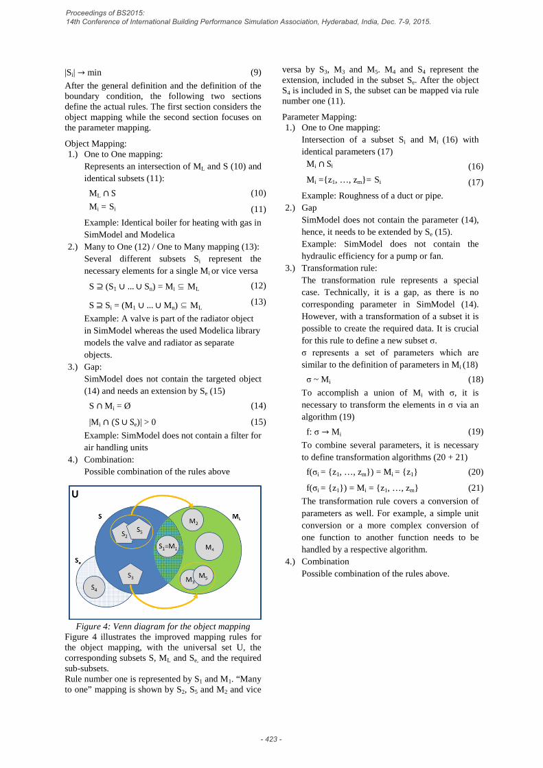
Figure 4: Venn diagram for the object mapping Figure 4 illustrates the improved mapping rules for the object mapping, with the universal set U, the corresponding subsets S, ML and Se, and the required sub-subsets. Rule number one is represented by S1 and M1. “Many to one” mapping is shown by S2, S5 and M2 and vice
versa by S3, M3 and M5. M4 and S4 represent the extension, included in the subset Se. After the object S4 is included in S, the subset can be mapped via rule number one (11).
Parameter Mapping: 1.) One to One mapping:
Intersection of a subset Si and Mi (16) with identical parameters (17)
Mi ∩ Si (16)
Mi ={z1, …, zm}= Si (17)
Example: Roughness of a duct or pipe. 2.) Gap
SimModel does not contain the parameter (14), hence, it needs to be extended by Se (15). Example: SimModel does not contain the hydraulic efficiency for a pump or fan.
3.) Transformation rule: The transformation rule represents a special case. Technically, it is a gap, as there is no corresponding parameter in SimModel (14). However, with a transformation of a subset it is possible to create the required data. It is crucial for this rule to define a new subset σ. σ represents a set of parameters which are similar to the definition of parameters in Mi (18)
σ ~ Mi (18)
To accomplish a union of Mi with σ, it is necessary to transform the elements in σ via an algorithm (19)
f: σ → Mi (19)
To combine several parameters, it is necessary to define transformation algorithms (20 + 21)
f(σi = {z1, …, zm}) = Mi = {z1} (20)
f(σi = {z1}) = Mi = {z1, …, zm} (21)
The transformation rule covers a conversion of parameters as well. For example, a simple unit conversion or a more complex conversion of one function to another function needs to be handled by a respective algorithm.
4.) Combination Possible combination of the rules above.
Proceedings of BS2015: 14th Conference of International Building Performance Simulation Association, Hyderabad, India, Dec. 7-9, 2015.
- 423 -

Figure 5: Venn diagram for the parameter mapping
Figure 5 visualises the improved parameter mapping. S1 and M1 contain identic parameters and represent the first rule. M2 represents the gap, which is closed by embedding the missing information in the SimModel data model via Se. σ3 and M3 represent a transformation from many parameters in the SimModel set to a single parameter on the Modelica side. At this point, it is necessary to use the transformation rule, as the user needs to implement algorithms (illustrated by f) to combine the parameters. The output of this algorithm is one single parameter on the Modelica side. The link of σ4 and M4 shows the use of one single parameter at the SimModel side to define multiple parameters on the Modelica side. The improved mapping rules refine the previously defined, original six mapping rules. The differentiation between object and parameter level is still present, but enhanced by using individual mapping rules. This improvement simplifies the understanding and implementation of mapping rules. The top part of Figure 6 shows the four rules for object mapping whereas the lower part depicts the four rules for parameter mapping. The original first rule (One to One) remains as previously defined in Wimmer et al. (2014a). The second and third rule are left unchanged for the object mapping, but are modified for the parameter mapping. It is necessary to implement algorithms for a combination of different parameters in order to integrate the “many to one” and “one to many” mapping on the parameter level as part of the transformation rule. The fourth rule, representing the gap, remains unchanged as well. This allows the user to add additional information to the data set of SimModel for the used library and to create an enhanced data basis for future mapping purposes. The transformation of objects is not part of the object level anymore and is only relevant for the parameter level. The last rule representing a combination is represented in both levels.
Figure 6: The improved mapping rules represent the
fundamental concept for the interface between SimModel and Modelica
LIMITATIONS The connection of the Modelica libraries with SimModel can be handled via the mapping rules. Nevertheless, this approach has some limitations. The BIM scheme – here in IFC format – is used as input data for BEPS. This is a relevant starting point for the information needed for a simulation, but the process needs more information in order to perform a BEPS. BIM is used as a basic input and SimModel functions as an upgrade for the relevant data, but the data needs even further extensions. In order to run a simulation, it is necessary to amend the work. The mapping rules do not tackle all the issues to create an executable Modelica model yet. Some information, like the arrangement of the components, the initial values or the graphical representation is not covered yet.
Proceedings of BS2015: 14th Conference of International Building Performance Simulation Association, Hyderabad, India, Dec. 7-9, 2015.
- 424 -

DISCUSSION The presented mapping process enables the connection of BIM with several Modelica libraries. Two actors are responsible for the mapping and the corresponding mapping table. The mapping table needs to be prepared with the information of each data model for the actual usage of the mapping rules. The information for the preparation needs to be extracted by the documentation of the different data models. Besides, the developers of the libraries have to provide the necessary knowledge to define the mapping rules and all libraries should include a minimum documentation, which allows the preparation of the corresponding mapping table. Because the definition of the objects and parameters of SimModel are adopted from EnergyPlus, the handbook of EnergyPlus provides the relevant documentation of SimModel. It is provided in a PDF-file, but this represents not an optimal format to parse and to extract the required information. The extraction process of the relevant information is cumbersome and needs some improvement to enable an automated process. On the other hand, the documentation of Modelica is mostly enclosed in the respective Modelica libraries. Without appropriate documentation, it is necessary to study the complete library’s source code, which is again very cumbersome and requires a deep knowledge of the Modelica language. The Energy-Consultant and the Simulation-Expert need to collaborate to prepare the mapping table and to define the mapping rules and algorithms. The Energy-Consultant is an expert for the SimModel side and the Simulation-Expert knows the details of each Modelica library. Within the completion of the mapping table, the Simulation-Expert decides which library and object suits best for the provided objects on the SimModel side. For this step, the Simulation-Expert needs to know which library is the preferred for the specific project. Each library is defined differently and covers different components. In addition, the purpose of each library is different, so that the granularity of the intended simulation should be clear. To decide which library suits best, the Simulation-Expert should know the focus of the project and what effect shall be evaluated with the simulation. In this paper, two actors are the responsible persons to deal with the mapping process, because of the required overarching knowledge on the SimModel and Modelica side. Considering a single, well-educated actor could be a possibility for creating the mapping table, applying the mapping rules and defining the algorithms. Besides, this actor would require deep knowledge of SimModel and the used Modelica libraries, which is usually not realistic. The mapping table provides an instrument and an optimal basis for the mapping process by using the mapping rules. With a complete mapping table, it is possible to do the mapping without deep knowledge
of the two data sets and the knowledge of the mapping has to be condensed within the mapping rules themselves. The rules give an easily manageable framework for the mapping, but the knowledge for the connection stays with the Energy-Consultant and the Simulation-Expert. They need to be able to formulate algorithms to link the two sets. Throughout the project, the used Modelica libraries changed frequently. The changes made it necessary to recreate affected links and the mapping was only stable for a specific version of the library. A standardized change log should enable the extraction of the relevant information on an up-to-date basis for an automated conversion process. Either the developer of the Modelica libraries or a different actor who is responsible to maintain the interface of SimModel with multiple Modelica libraries should provide such a change log.
CONCLUSION The presented approach tackles the task of connecting a rigidly defined data model with a flexible data structure. As the definitions of SimModel change frequently, but less often than the Modelica libraries, continuous adaptations have to be done on the mapping rule side. The changes to the Modelica libraries are not foreseeable and cannot be included in a standardised interface. Therefore, the interface needs to provide a flexible approach to bridge the gap between BIM and Modelica. Thus, the presented mapping rules help to develop a user friendly API for connecting SimModel with Modelica and allow a data flow from BIM to Modelica.
FUTURE WORK The next step consists of proving that the presented concept presents a realistic use case applied with a complex Modelica library. The development of a realistic use case is already in progress, consisting of a three-story office building with different thermal zones and multiple HVAC-systems. Another possible enhancement will be a graphical user interface (GUI) that provides a display for handling the flexible interface by using the mapping rules.
ACKNOWLEDGMENTS This work emerged from the Annex 601 project, an international project conducted under the umbrella of the International Energy Agency (IEA) within the Energy in Buildings and Communities (EBC) Programme. Annex 60 will develop and demonstrate new generation computational tools for building and community energy systems based on Modelica, Functional Mockup Interface and BIM standards.
The work is also conducted within the German research project EnEff-BIM, Energy Efficient
1 IEA EBC Annex 60, http://www.iea-annex60.org
Proceedings of BS2015: 14th Conference of International Building Performance Simulation Association, Hyderabad, India, Dec. 7-9, 2015.
- 425 -
Modeling and Simulation Based on Building Information Modeling, was funded by the BMWi2 under Contract No. 03ET1177A.
REFERENCES Baetens, Coninck, van Roy, Verbruggen, Driesen,
Helsen, and Saelens. “Assessing electrical bottlenecks at feeder level for residential net zero-energy buildings by integrated system simulation.” Applied Energy, pp. 74–83, 2011.
Building Smart Alliance. “buildingSmart: International home of openBIM.” 2014. http://www.buildingsmart-tech.org/, accessed June 2014.
Cao, Wimmer, Thorade, Maile, O'Donnell, Rädler, Frisch, and van Treeck. “A Flexible Model Transformation to Link BIM with Different Modelica Libraries for Building Energy.” In IBPSA Building Simulation Conference 2015. Hyderabad, 2015.
Cao, Jun, Maile, Tobias, O'Donnell, James, Wimmer, Reinhard, and van Treeck, Christoph. “Model Transformation from SimModel to Modelica for Building Energy Performance Simulation.” In BauSim 2014, 2014.
Constantin, Streblow, and Müller. “The Modelica HouseModels Library: Presentation and Evaluation of a Room Model with the ASHRAE Standard 140.”, pp. 293–299, 2014.
Eastman, BIM handbook: A guide to building information modeling for owners, managers, designers, engineers, and contractors, second edition. 2nd ed. Hoboken, N.J: John Wiley & Sons, 2011.
EnergyPlus Development Team. EnergyPlus Engineering Reference: The Reference to EnergyPlus Calculations. Berkeley, 2013a 2013.
EnergyPlus Development Team. Input Output Reference: The Encyclopedic Reference to EnergyPlus Input and Output: Canada Construction Association, 2013b.
Hua. “Entwicklung einer Schnittstelle zwischen IFC-Gebäudemodellen und Modelica.” Master thesis, München, 2014.
Jeong, Kim, Clayton, Haberl, and Yan. “Translating building information modeling to building energy modeling using model view definition.” 2014.
Lauster, Teichmann, Fuchs, Streblow, and Mueller. “Low order thermal network models for dynamic simulations of buildings on city district scale.” Building and Environment, pp. 223–231, 2014.
O'Donnell, See, Rose, Maile, Bazjanac, and Haves. “SimModel: A domain data model for whole building energy simulation.” In Building Simulation. Sydney, 2011.
2 The German Federal Ministry for Economic Affairs and Energy, http://www.bmwi.de
Pahl, and Damrath. Mathematische Grundlagen der Ingenieurinformatik. 1st ed. Berlin: Springer-Verlag Berlin Heidelberg, 2000.
Remmen, Cao, Frisch, Lauster, Maile, O'Donnell, Rädler, Streblow, Thorade, Wimmer, Müller, Nytsch-Geussen, and van Treeck. “An Open Framework For Integrated BIM-Based Building Performance Simulation Using Modelica.” In IBPSA Building Simulation Conference 2015. Hyderabad, 2015.
van Treeck, and Rank. “Dimensional reduction of 3D building models using graph theory and its application in building energy simulation.” Engineering with Computers 23, no. 2, pp. 109–122, 2007.
Wetter, Zuo, Nouidui, and Pang. “Modelica Buildings library.” Journal of Building Performance Simulation 7, no. 4, pp. 253–270, 2014.
Wimmer, Maile, O'Donnell, Cao, and van Treeck. “Data-Requirements Specification to Support BIM-based HVAC-Definitions in Modelica.” In Human-centred building(s): BauSIM 2014, edited by International Building Performance Simulation Association. Aachen, 2014.
Proceedings of BS2015: 14th Conference of International Building Performance Simulation Association, Hyderabad, India, Dec. 7-9, 2015.
- 426 -