implementation of distributed control architecture for...
TRANSCRIPT
Chapter 4
© 2012 Yasuda, licensee InTech. This is an open access chapter distributed under the terms of the Creative Commons Attribution License (http://creativecommons.org/licenses/by/3.0), which permits unrestricted use, distribution, and reproduction in any medium, provided the original work is properly cited.
Implementation of Distributed Control Architecture for Multiple Robot Systems Using Petri Nets
Gen’ichi Yasuda
Additional information is available at the end of the chapter
http://dx.doi.org/10.5772/50577
1. Introduction
Because of the generality of the robot’s physical structure, control and reprogrammability, it is expected that more and more robots will be introduced into industry to automate various operations. This flexibility can be exploited if the robot control system can be programmed easily. Anyway, it is quite obvious that a single robot cannot perform effective tasks in an industrial environment, unless it is provided with some additional equipment. For example, in building a component, two robots are required to cooperate, one holding some part while the other attaches some other part to it. In other tasks, robots may pursue different goals, making sure that they both don’t attempt to use the same resource at the same time. Such synchronization and coordination can only be achieved by getting the robots to talk to each other or to some supervising agent. However, for large-scaled and complicated manufacturing systems, from the viewpoint of cost-performance and reliability appropriate representation and analysis methods of the control system have not sufficiently been established [1]. The lack of adequate programming tools for multiple robots make some tasks impossible to be performed. In other cases, since the control requirements are diversified and often changed, the cost of programming may be a significant fraction of the total cost of an application. Due to these reasons, the development of an effective programming method to integrate a system which includes various robots and other devices that cooperate in the same task is urgently required [2].
In programming by the well-known teaching-playback or teaching by showing, the programmer specifies a single execution for the robot: there are no loops, no conditionals, no data retrieval, nor computations. This method can be implemented without a general-purpose computer, and it is especially adequate for some applications, such as spot welding, painting, and simple materials handling. In other applications such as mechanical assembly
Petri Nets – Manufacturing and Computer Science 76
and inspection, robot-level languages provide computer programming languages with commands to access sensors and to specify robot motions, enabling the data from external sensors, such as vision and force, to be used in modifying the robot’s motion. Many recent methods in robot programming provide the power of robot-level languages without requiring deep programming knowledge, extending the basic philosophy of teaching to include decision-making based on sensing. Another method, known as task-level programming [3], [4], requires specifying goals for the positions of objects, rather than the motions of the robot needed to achieve those goals. A task-level specification is meant to be completely robot-independent; no positions or paths specified by the user depend on the robot geometry or kinematics. This method requires complete geometric models of the environment and of the robot, referred to as world-modeling systems. An object oriented approach has been held for modeling, simulation and control of multiple robot systems and intelligent manufacturing systems [5]-[9]. The main drawback of these methods relative to teaching is that they require the robot programmer to be an expert in computer programming and in the design of sensor-based motion strategies. Hence, this method is not accessible to the typical worker on the factory floor [10], [11].
Robot program development is often ignored in the design of robot control systems and, consequently, complex robot programs can be very difficult to debug. The development of robot programs has several characteristics which need special treatment. Because robot programs have complex side-effects and their execution time is usually long, it is not always feasible to re-initialize the program upon failure. So, robot programming systems should allow programs to be modified on-line and immediately restarted. Sensory information and real-time interactions are crucial and not usually repeatable. The ability to record the sensor outputs, together with program traces should be provided as a real-time debugging tool. Further, because complex geometry and motions are difficult to visualize, 3D graphic simulators can play an important role. Another difficulty comes from the fact that each robot has its own programming system, and it is often undesirable to alter or substitute it with something else. Besides cost considerations, this is because each robot programming language is tailored to the machine it has to control, and it would be simply impossible, for example to obtain a good performance from an articulated robot using a language designed for a Cartesian one. To attend the above requirements, a universal robot programming method with real-time automatic translation from a robot language to another one is required in integrated manufacturing systems.
The decision was then taken to develop a robot programming method for multiple robot systems that would provide the following characteristics. All the activities of the global system should be supervised by the control system, which is the method suitable to the integrated management that is necessary in manufacturing systems. So the integral controller with the strong computational power to do the complex task of the coordination system is needed. According to the parallelism among the subtasks in the multi-robot coordination system, advantage of the parallel architecture of the control system is taken to reach the good control capabilities [12]. To give a prior attention to the requirements about the part flow control, the control algorithm is designed based on the Petri net [13]. The Petri
Implementation of Distributed Control Architecture for Multiple Robot Systems Using Petri Nets 77
net can describe parallel flows, design and implement real-time robot control tasks [14]-[16], so that the process schedule is easily and effectively laid down, inspected and corrected. Each robot may be programmed in its own language in order to maintain best performance of each machine. Each step of the programming procedure can be verified by graphic simulation in order to improve the interaction between the operator and the robots and to make possible the off-line programming.
In this chapter, the method described in the previous work [17] is applied to program cooperative tasks by multiple robots and to concurrently control real robots. The aim of this chapter is to describe and implement a programming and execution system based on Petri nets that allows easy programming of a control system which includes multiple different robots and a variety of auxiliary devices. The problem how the control and coordination algorithms based on Petri nets are realized in an example of two robots carrying parts cooperatively is resolved.
2. Net models of robotic processes
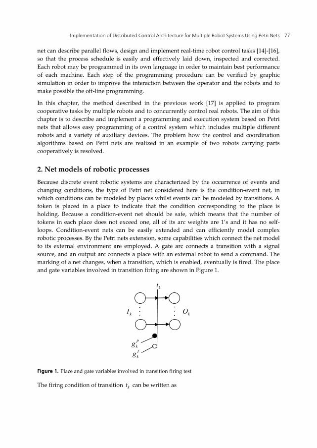
Because discrete event robotic systems are characterized by the occurrence of events and changing conditions, the type of Petri net considered here is the condition-event net, in which conditions can be modeled by places whilst events can be modeled by transitions. A token is placed in a place to indicate that the condition corresponding to the place is holding. Because a condition-event net should be safe, which means that the number of tokens in each place does not exceed one, all of its arc weights are 1’s and it has no self-loops. Condition-event nets can be easily extended and can efficiently model complex robotic processes. By the Petri nets extension, some capabilities which connect the net model to its external environment are employed. A gate arc connects a transition with a signal source, and an output arc connects a place with an external robot to send a command. The marking of a net changes, when a transition, which is enabled, eventually is fired. The place and gate variables involved in transition firing are shown in Figure 1.
Pkg
kI kO‧ ‧ ‧
‧ ‧ ‧
Ikg
kt
Figure 1. Place and gate variables involved in transition firing test
The firing condition of transition kt can be written as
Petri Nets – Manufacturing and Computer Science 78
( )k k
P Ik i j k k
i I j Ot p p g g
(1)
where denotes the logical product operation, and
kI : set of input places of transition kt
kO : set of output places of transition kt Pkg : logical variable of permissive gate condition of transition kt Ikg : logical variable of inhibitive gate condition of transition kt
The marking change of input and output places of transition kt can be written as follows:
,,
i k i k i
j k j k j
For p I p t pFor p O p t p
(2)
If a place has two or more input transitions or output transitions, these transitions may be in conflict for firing. When two or more transitions are enabled only one transition should be fired using some arbitration rule. Well-known properties of the condition-event net are as follows. From (1), if the directions of the input and output arcs of a place and the existence of token in the place are reversed, the firing conditions of all the transitions in the net are unchanged. If there is no conflict place in a net, then the net can be transformed into a net with no loop. If there is a loop with no conflict place in a net, the number of tokens in the loop is unchanged. In case that initially there is no token in a net marking, if there are parallel paths between two transitions, the maximum number of tokens in each path is equal to the minimum number of places in each path. So, by addition of a dummy path with a specified number of places, the number of tokens in each path can be controlled.
The dynamic behavior of the system represented by a net model is simulated using the enabling and firing rules. One cycle of the simulation comprises the following steps, which are executed when some gate condition is changed.
1. Calculate the logical variable of the transition associated with the new gate condition using (1).
2. If the transition is fired, calculate the logical variables of its input and output places using (2).
3. Then the marking is changed and a new command is sent to the corresponding robot.
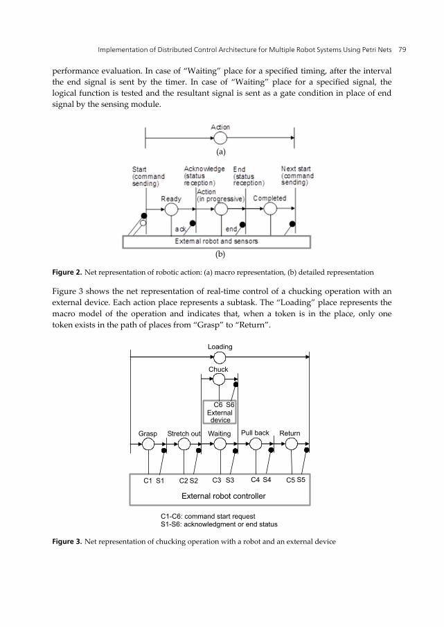
In any initial marking, there must not be more than one token in a place. According to these rules, the number of tokens in a place never exceeds one; the net is essentially a safe graph. A robotic action is modeled by two transitions and one condition as shown in Figure 2. At the “Start” transition the command associated with the transition is sent to the corresponding robot or machine. At the “End” transition the status report is received. When a token is present in the “Action” place, the action is in progressive. The “Completed” place can be omitted, and then the “End” transition is fused with the “Start” transition of the next action. Activities can be assigned an amount of time units to monitor them in time for real
Implementation of Distributed Control Architecture for Multiple Robot Systems Using Petri Nets 79
performance evaluation. In case of “Waiting” place for a specified timing, after the interval the end signal is sent by the timer. In case of “Waiting” place for a specified signal, the logical function is tested and the resultant signal is sent as a gate condition in place of end signal by the sensing module.
Figure 2. Net representation of robotic action: (a) macro representation, (b) detailed representation
Figure 3 shows the net representation of real-time control of a chucking operation with an external device. Each action place represents a subtask. The “Loading” place represents the macro model of the operation and indicates that, when a token is in the place, only one token exists in the path of places from “Grasp” to “Return”.
Chuck
External device
Grasp Stretch out
External robot controller
S1 S2 S3 S4 C1 C2 C3 C4
C1-C6: command start request S1-S6: acknowledgment or end status
Waiting Pull back Return
C5 S5
C6 S6
Loading
Figure 3. Net representation of chucking operation with a robot and an external device
(a)
(b)
Petri Nets – Manufacturing and Computer Science 80
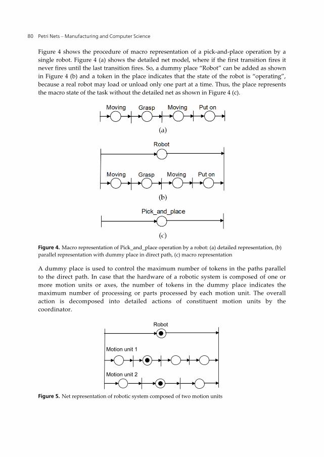
Figure 4 shows the procedure of macro representation of a pick-and-place operation by a single robot. Figure 4 (a) shows the detailed net model, where if the first transition fires it never fires until the last transition fires. So, a dummy place “Robot” can be added as shown in Figure 4 (b) and a token in the place indicates that the state of the robot is “operating”, because a real robot may load or unload only one part at a time. Thus, the place represents the macro state of the task without the detailed net as shown in Figure 4 (c).
Figure 4. Macro representation of Pick_and_place operation by a robot: (a) detailed representation, (b) parallel representation with dummy place in direct path, (c) macro representation
A dummy place is used to control the maximum number of tokens in the paths parallel to the direct path. In case that the hardware of a robotic system is composed of one or more motion units or axes, the number of tokens in the dummy place indicates the maximum number of processing or parts processed by each motion unit. The overall action is decomposed into detailed actions of constituent motion units by the coordinator.
Robot
Motion unit 1
Motion unit 2
Figure 5. Net representation of robotic system composed of two motion units
Implementation of Distributed Control Architecture for Multiple Robot Systems Using Petri Nets 81
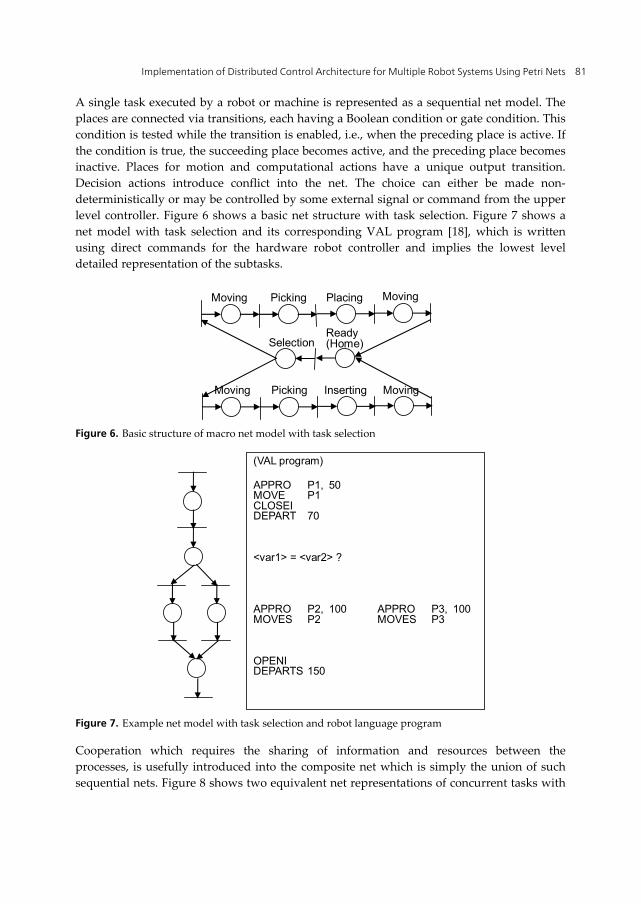
A single task executed by a robot or machine is represented as a sequential net model. The places are connected via transitions, each having a Boolean condition or gate condition. This condition is tested while the transition is enabled, i.e., when the preceding place is active. If the condition is true, the succeeding place becomes active, and the preceding place becomes inactive. Places for motion and computational actions have a unique output transition. Decision actions introduce conflict into the net. The choice can either be made non-deterministically or may be controlled by some external signal or command from the upper level controller. Figure 6 shows a basic net structure with task selection. Figure 7 shows a net model with task selection and its corresponding VAL program [18], which is written using direct commands for the hardware robot controller and implies the lowest level detailed representation of the subtasks.
Ready (Home) Selection
Moving Moving Picking Placing
Moving Moving Picking Inserting
Figure 6. Basic structure of macro net model with task selection
(VAL program) APPRO P1, 50 MOVE P1 CLOSEI DEPART 70 <var1> = <var2> ? APPRO P2, 100 APPRO P3, 100 MOVES P2 MOVES P3 OPENI DEPARTS 150
Figure 7. Example net model with task selection and robot language program
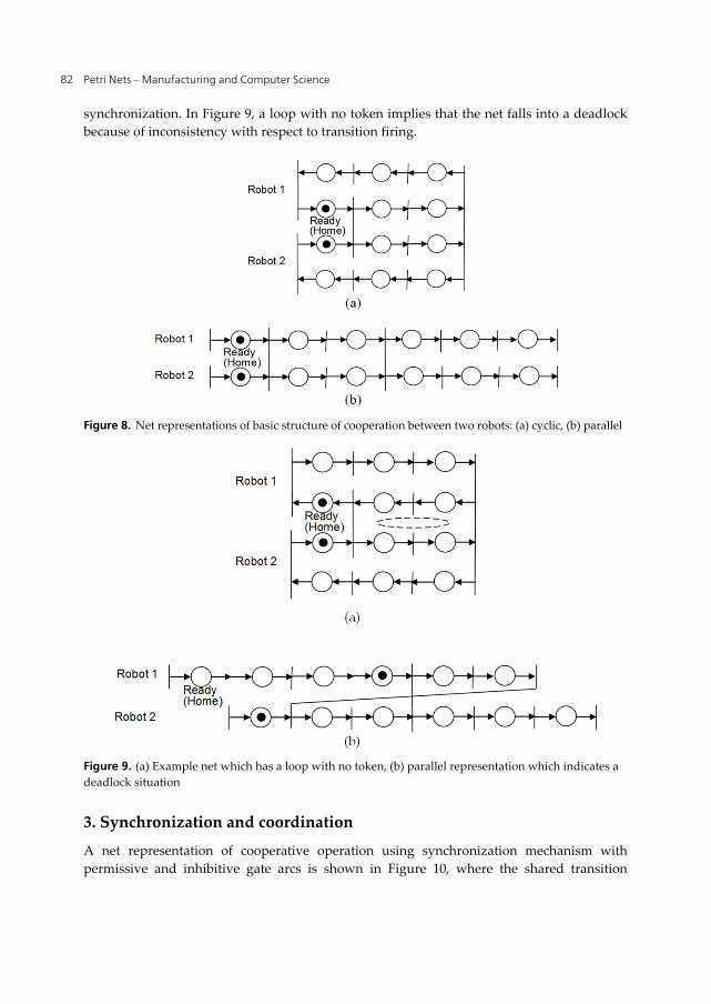
Cooperation which requires the sharing of information and resources between the processes, is usefully introduced into the composite net which is simply the union of such sequential nets. Figure 8 shows two equivalent net representations of concurrent tasks with
Petri Nets – Manufacturing and Computer Science 82
synchronization. In Figure 9, a loop with no token implies that the net falls into a deadlock because of inconsistency with respect to transition firing.
Figure 8. Net representations of basic structure of cooperation between two robots: (a) cyclic, (b) parallel
Figure 9. (a) Example net which has a loop with no token, (b) parallel representation which indicates a deadlock situation
3. Synchronization and coordination
A net representation of cooperative operation using synchronization mechanism with permissive and inhibitive gate arcs is shown in Figure 10, where the shared transition
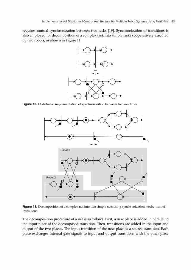
Implementation of Distributed Control Architecture for Multiple Robot Systems Using Petri Nets 83
requires mutual synchronization between two tasks [19]. Synchronization of transitions is also employed for decomposition of a complex task into simple tasks cooperatively executed by two robots, as shown in Figure 11.
Figure 10. Distributed implementation of synchronization between two machines
Robot 1
Robot 2
Figure 11. Decomposition of a complex net into two simple nets using synchronization mechanism of transitions
The decomposition procedure of a net is as follows. First, a new place is added in parallel to the input place of the decomposed transition. Then, transitions are added in the input and output of the two places. The input transition of the new place is a source transition. Each place exchanges internal gate signals to input and output transitions with the other place
Petri Nets – Manufacturing and Computer Science 84
when a token is in the place. The gate arcs are implemented using asynchronous communication between different robots.
4. Net based multiple robot coordination
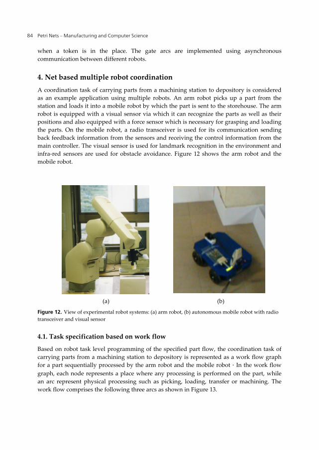
A coordination task of carrying parts from a machining station to depository is considered as an example application using multiple robots. An arm robot picks up a part from the station and loads it into a mobile robot by which the part is sent to the storehouse. The arm robot is equipped with a visual sensor via which it can recognize the parts as well as their positions and also equipped with a force sensor which is necessary for grasping and loading the parts. On the mobile robot, a radio transceiver is used for its communication sending back feedback information from the sensors and receiving the control information from the main controller. The visual sensor is used for landmark recognition in the environment and infra-red sensors are used for obstacle avoidance. Figure 12 shows the arm robot and the mobile robot.
Figure 12. View of experimental robot systems: (a) arm robot, (b) autonomous mobile robot with radio transceiver and visual sensor
4.1. Task specification based on work flow
Based on robot task level programming of the specified part flow, the coordination task of carrying parts from a machining station to depository is represented as a work flow graph for a part sequentially processed by the arm robot and the mobile robot.In the work flow graph, each node represents a place where any processing is performed on the part, while an arc represent physical processing such as picking, loading, transfer or machining. The work flow comprises the following three arcs as shown in Figure 13.
(a) (b)
Implementation of Distributed Control Architecture for Multiple Robot Systems Using Petri Nets 85
1. picking from the station pallet by the arm robot 2. loading into the mobile robot by the arm robot 3. transfer from the station to the depository by the mobile robot
Station Arm robot Mobile robot Depository Picking Loading Transfer
Figure 13. Task specification based on work flow processed on parts
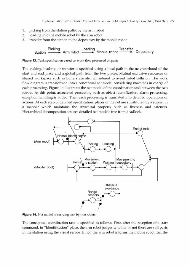
The picking, loading, or transfer is specified using a local path in the neighborhood of the start and end place and a global path from the two places. Mutual exclusive resources or shared workspace such as buffers are also considered to avoid robot collision. The work flow diagram is transformed into a conceptual net model considering machines in charge of each processing. Figure 14 illustrates the net model of the coordination task between the two robots. At this point, associated processing such as object identification, alarm processing, exception handling is added. Then each processing is translated into detailed operations or actions. At each step of detailed specification, places of the net are substituted by a subnet in a manner which maintains the structural property such as liveness and safeness. Hierarchical decomposition assures detailed net models free from deadlock.
Loading Picking
Identification
Waiting Movementto station
Movement todepository
Obstacleavoidance
Range sensors
Home
End of task
Home
(Arm robot)
(Mobile robot)
Figure 14. Net model of carrying task by two robots
The conceptual coordination task is specified as follows. First, after the reception of a start command, in “Identification” place, the arm robot judges whether or not there are still parts in the station using the visual sensor. If not, the arm robot informs the mobile robot that the
Petri Nets – Manufacturing and Computer Science 86
task has been finished with “End of task” place and returns back to its home position. On the contrary, the arm robot starts to get the position of a part and grasp it. The mobile robot moves to the station, and the arm robot, after the completion of the “Grasp” subtask and the “Movement to station” subtask, starts “Loading” subtask while the mobile robot waits at the specified position. After the completion of loading, the mobile robot moves to the depository, and the arm robot executes the “Identification” subtask repeatedly. If the signal of “End of task” is on, the mobile robot returns back to its home position, and if not it moves to the station. From the “Movement to station” and “Movement to depository” places, the gate signal is sent to repeatedly execute the “Obstacle avoidance” subtask using infrared range sensors. In the coordination task, synchronization is represented as a shared transition which is implemented using a sequence of asynchronous communications as shown in Figure 10.
4.2. Subtask control of arm robots
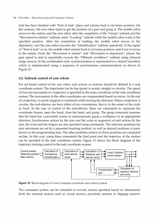
For net based control of the arm robot, unit actions or motions should be defined in a task coordinate system. The trajectories can be free (point to point), straight or circular. The speed of forward movement of a trajectory is specified in the main coordinate of the task coordinate system. The movements in the other coordinates are compensated based on errors. At the end of a trajectory, it can be stopped or continued while turning the direction. When a trajectory is circular, the end-effector can have either of two orientations, that is, to the center of the circle or fixed. In the case of control of the end-effector, there are commands to represent the coordinate frames, open the hand, close the hand, and grasp. The grasp command assumes that the hand has a proximity sensor to autonomously grasp a workpiece in an appropriate direction. Synchronous actions by the arm and the wrist or sequences of unit actions by the arm, the wrist and the fingers are also specified using commands. The reference positions for arm movement are set by a separated teaching method, as well as desired positions of parts known at the programming time. The other positions relative to these positions are computed on-line. In this way, using these commands the final point and the trajectory of the motion can be specified in the task coordinate system. Figure 15 shows the block diagram of the trajectory tracking control in the task coordinate system.
Calculation of homogenous transformation
Calculation of main velocity vector
Calculation of reference axis velocity vector
3-axis Cartesian control system
Calculation of trajectory distance and errors
Compensation gain
Current position Reference position Main velocity
Figure 15. Block diagram of 3-axis Cartesian coordinate arm control system
The command system can be extended to execute actions specified based on information from the external sensors such as visual sensors, proximity sensors or slippage sensors.
Implementation of Distributed Control Architecture for Multiple Robot Systems Using Petri Nets 87
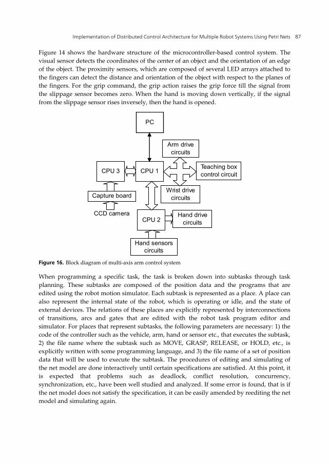
Figure 14 shows the hardware structure of the microcontroller-based control system. The visual sensor detects the coordinates of the center of an object and the orientation of an edge of the object. The proximity sensors, which are composed of several LED arrays attached to the fingers can detect the distance and orientation of the object with respect to the planes of the fingers. For the grip command, the grip action raises the grip force till the signal from the slippage sensor becomes zero. When the hand is moving down vertically, if the signal from the slippage sensor rises inversely, then the hand is opened.
CPU 1
CPU 2
Arm drive circuits
Wrist drive circuits
Hand sensorscircuits
Hand drive circuits
CPU 3
CCD camera
Capture board
PC
Teaching boxcontrol circuit
Figure 16. Block diagram of multi-axis arm control system
When programming a specific task, the task is broken down into subtasks through task planning. These subtasks are composed of the position data and the programs that are edited using the robot motion simulator. Each subtask is represented as a place. A place can also represent the internal state of the robot, which is operating or idle, and the state of external devices. The relations of these places are explicitly represented by interconnections of transitions, arcs and gates that are edited with the robot task program editor and simulator. For places that represent subtasks, the following parameters are necessary: 1) the code of the controller such as the vehicle, arm, hand or sensor etc., that executes the subtask, 2) the file name where the subtask such as MOVE, GRASP, RELEASE, or HOLD, etc., is explicitly written with some programming language, and 3) the file name of a set of position data that will be used to execute the subtask. The procedures of editing and simulating of the net model are done interactively until certain specifications are satisfied. At this point, it is expected that problems such as deadlock, conflict resolution, concurrency, synchronization, etc., have been well studied and analyzed. If some error is found, that is if the net model does not satisfy the specification, it can be easily amended by reediting the net model and simulating again.
Petri Nets – Manufacturing and Computer Science 88
4.3. Subtask control of mobile robots
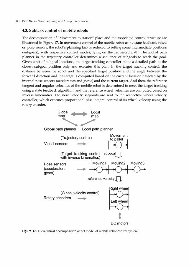
The decomposition of “Movement to station” place and the associated control structure are illustrated in Figure 17. In movement control of the mobile robot using state feedback based on pose sensors, the robot’s planning task is reduced to setting some intermediate positions (subgoals), with respective control modes, lying on the requested path. The global path planner in the trajectory controller determines a sequence of subgoals to reach the goal. Given a set of subgoal locations, the target tracking controller plans a detailed path to the closest subgoal position only and executes this plan. In the target tracking control, the distance between the robot and the specified target position and the angle between the forward direction and the target is computed based on the current location detected by the internal pose sensors (accelerators and gyros) and the current target. And then, the reference tangent and angular velocities of the mobile robot is determined to meet the target tracking using a state feedback algorithm, and the reference wheel velocities are computed based on inverse kinematics. The new velocity setpoints are sent to the respective wheel velocity controller, which executes proportional plus integral control of its wheel velocity using the rotary encoder.
Moving3Moving1 Moving2
Movementto pallet
(Wheel velocity control)
(Trajectory control)
(Target tracking control with inverse kinematics)
Right wheel
Left wheel
DC motors
Rotary encoders
Pose sensors (accelerators, gyros)
Visual sensors
subgoal
reference velocity
Global map
Local map
Global path planner Local path planner
Figure 17. Hierarchical decomposition of net model of mobile robot control system
Implementation of Distributed Control Architecture for Multiple Robot Systems Using Petri Nets 89
In case of detection of a blockage on the intended path, the trajectory controller receives a failure notification from the visual sensor, then modifies the subgoals and the short term local knowledge of the robot’s surroundings and triggers the target tracking in view of this change to the local environment knowledge. The trajectory controller has the dynamic map with global and local representation that becomes more accurate as the robot moves. Upon reaching this subgoal location, its local map will change based on the perceptual information using the PSD data extracted during motion. Then the target tracking controller triggers the local path planner to generate a path from the new location to the next subgoal location. When the lowest-level wheel velocity control fails to make progress, the target tracking controller attempts to find a way past the obstacle by turning the robot in position and trying again. The trajectory controller decides when and if new information integrated into the local map can be copied into the global map.
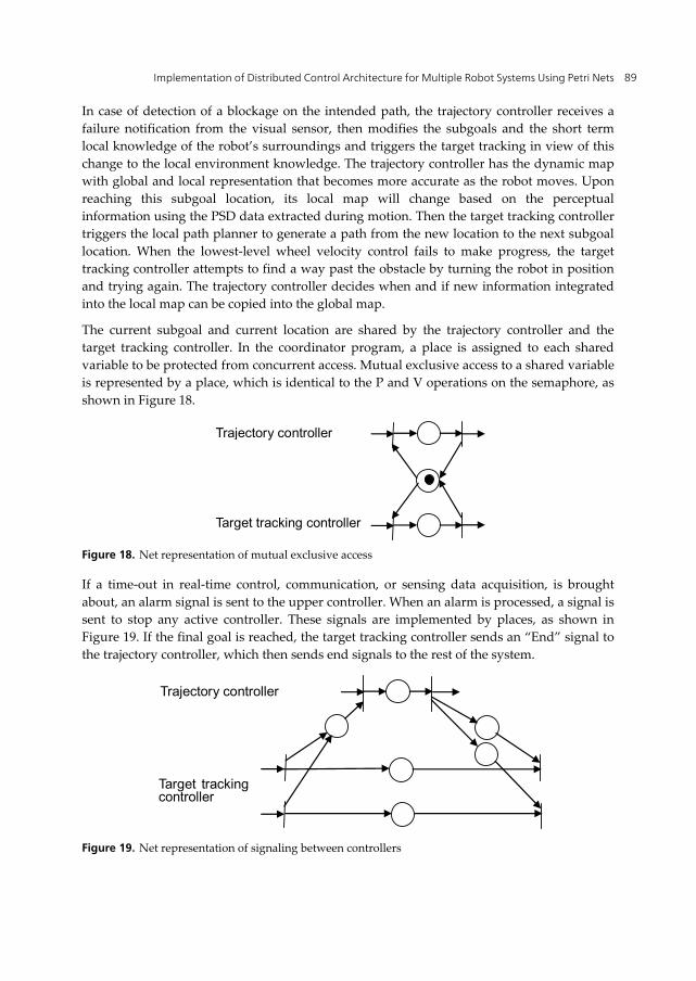
The current subgoal and current location are shared by the trajectory controller and the target tracking controller. In the coordinator program, a place is assigned to each shared variable to be protected from concurrent access. Mutual exclusive access to a shared variable is represented by a place, which is identical to the P and V operations on the semaphore, as shown in Figure 18.
Target tracking controller
Trajectory controller
Figure 18. Net representation of mutual exclusive access
If a time-out in real-time control, communication, or sensing data acquisition, is brought about, an alarm signal is sent to the upper controller. When an alarm is processed, a signal is sent to stop any active controller. These signals are implemented by places, as shown in Figure 19. If the final goal is reached, the target tracking controller sends an “End” signal to the trajectory controller, which then sends end signals to the rest of the system.
Trajectory controller
Target tracking controller
Figure 19. Net representation of signaling between controllers
Petri Nets – Manufacturing and Computer Science 90
5. Implementation of net based control system
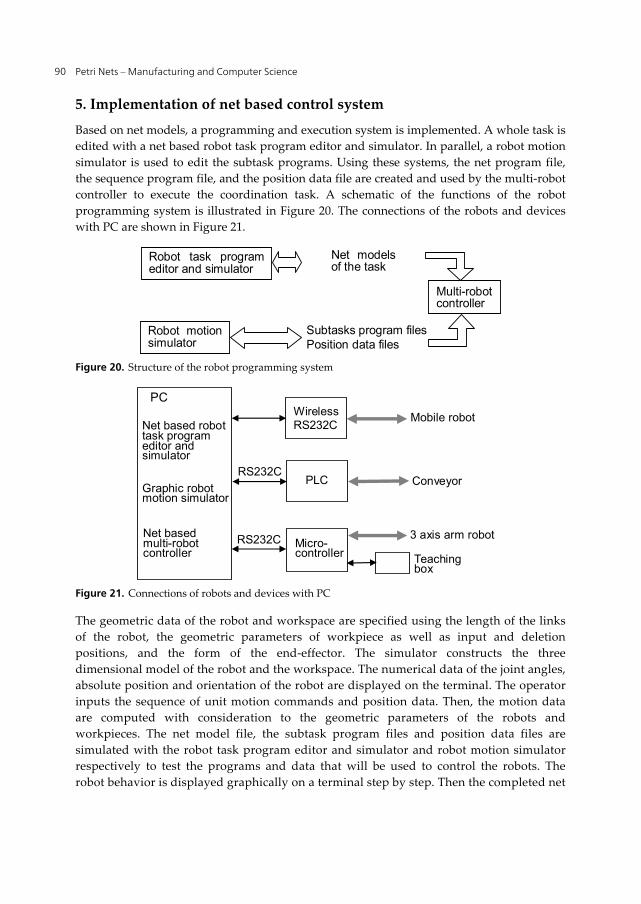
Based on net models, a programming and execution system is implemented. A whole task is edited with a net based robot task program editor and simulator. In parallel, a robot motion simulator is used to edit the subtask programs. Using these systems, the net program file, the sequence program file, and the position data file are created and used by the multi-robot controller to execute the coordination task. A schematic of the functions of the robot programming system is illustrated in Figure 20. The connections of the robots and devices with PC are shown in Figure 21.
Robot motion simulator
Robot task program editor and simulator
Net models of the task
Subtasks program files Position data files
Multi-robot controller
Figure 20. Structure of the robot programming system
PC
Micro- controller Teaching
box
RS232C
RS232C PLC
WirelessRS232C
Conveyor
3 axis arm robot
Mobile robot Net based robot task program editor and simulator
Graphic robot motion simulator
Net based multi-robot controller
Figure 21. Connections of robots and devices with PC
The geometric data of the robot and workspace are specified using the length of the links of the robot, the geometric parameters of workpiece as well as input and deletion positions, and the form of the end-effector. The simulator constructs the three dimensional model of the robot and the workspace. The numerical data of the joint angles, absolute position and orientation of the robot are displayed on the terminal. The operator inputs the sequence of unit motion commands and position data. Then, the motion data are computed with consideration to the geometric parameters of the robots and workpieces. The net model file, the subtask program files and position data files are simulated with the robot task program editor and simulator and robot motion simulator respectively to test the programs and data that will be used to control the robots. The robot behavior is displayed graphically on a terminal step by step. Then the completed net
Implementation of Distributed Control Architecture for Multiple Robot Systems Using Petri Nets 91
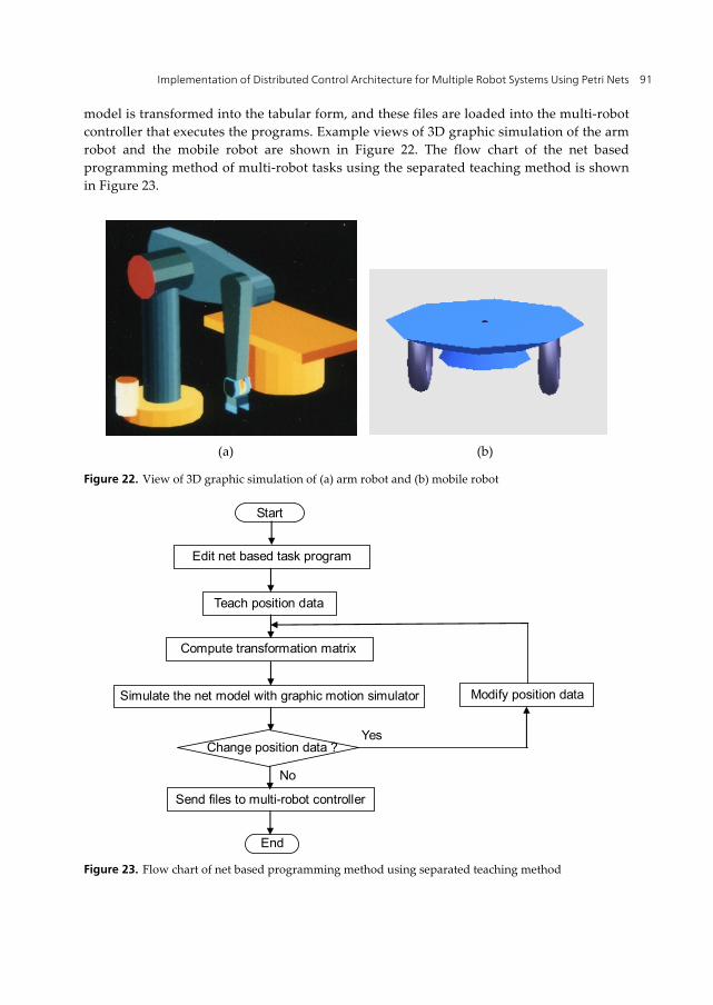
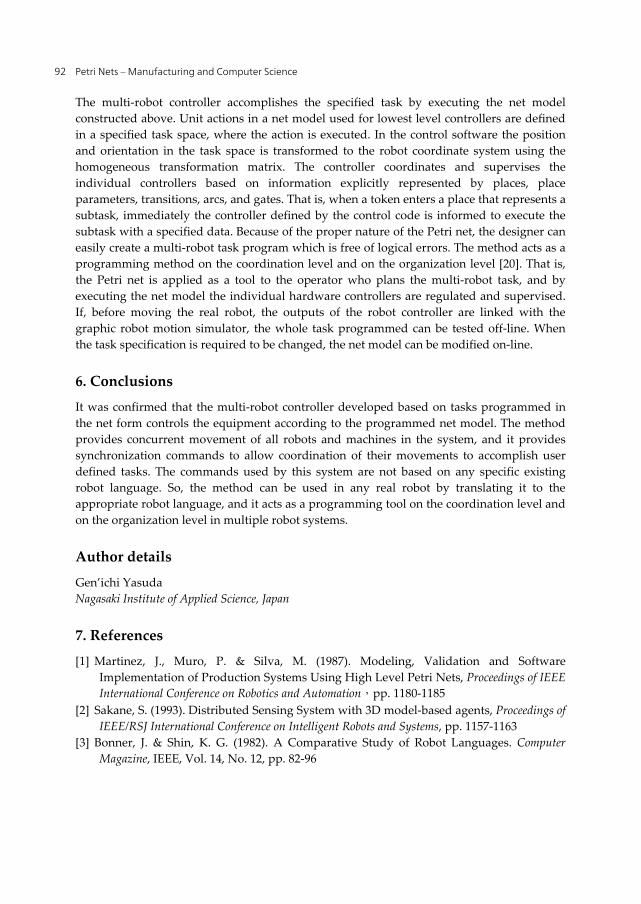
model is transformed into the tabular form, and these files are loaded into the multi-robot controller that executes the programs. Example views of 3D graphic simulation of the arm robot and the mobile robot are shown in Figure 22. The flow chart of the net based programming method of multi-robot tasks using the separated teaching method is shown in Figure 23.
Figure 22. View of 3D graphic simulation of (a) arm robot and (b) mobile robot
Start
Edit net based task program
Change position data ? Yes
Compute transformation matrix
Simulate the net model with graphic motion simulator
Send files to multi-robot controller
Teach position data
No
Modify position data
End Figure 23. Flow chart of net based programming method using separated teaching method
(a) (b)
Petri Nets – Manufacturing and Computer Science 92
The multi-robot controller accomplishes the specified task by executing the net model constructed above. Unit actions in a net model used for lowest level controllers are defined in a specified task space, where the action is executed. In the control software the position and orientation in the task space is transformed to the robot coordinate system using the homogeneous transformation matrix. The controller coordinates and supervises the individual controllers based on information explicitly represented by places, place parameters, transitions, arcs, and gates. That is, when a token enters a place that represents a subtask, immediately the controller defined by the control code is informed to execute the subtask with a specified data. Because of the proper nature of the Petri net, the designer can easily create a multi-robot task program which is free of logical errors. The method acts as a programming method on the coordination level and on the organization level [20]. That is, the Petri net is applied as a tool to the operator who plans the multi-robot task, and by executing the net model the individual hardware controllers are regulated and supervised. If, before moving the real robot, the outputs of the robot controller are linked with the graphic robot motion simulator, the whole task programmed can be tested off-line. When the task specification is required to be changed, the net model can be modified on-line.
6. Conclusions
It was confirmed that the multi-robot controller developed based on tasks programmed in the net form controls the equipment according to the programmed net model. The method provides concurrent movement of all robots and machines in the system, and it provides synchronization commands to allow coordination of their movements to accomplish user defined tasks. The commands used by this system are not based on any specific existing robot language. So, the method can be used in any real robot by translating it to the appropriate robot language, and it acts as a programming tool on the coordination level and on the organization level in multiple robot systems.
Author details
Gen’ichi Yasuda Nagasaki Institute of Applied Science, Japan
7. References
[1] Martinez, J., Muro, P. & Silva, M. (1987). Modeling, Validation and Software Implementation of Production Systems Using High Level Petri Nets, Proceedings of IEEE International Conference on Robotics and Automation,pp. 1180-1185
[2] Sakane, S. (1993). Distributed Sensing System with 3D model-based agents, Proceedings of IEEE/RSJ International Conference on Intelligent Robots and Systems, pp. 1157-1163
[3] Bonner, J. & Shin, K. G. (1982). A Comparative Study of Robot Languages. Computer Magazine, IEEE, Vol. 14, No. 12, pp. 82-96
Implementation of Distributed Control Architecture for Multiple Robot Systems Using Petri Nets 93
[4] Lozano-Perez, T. (1983). Robot Programming. Proceedings of the IEEE, Vol. 71, No. 7, pp. 821-841
[5] Yasuda, G. (1996). An Object-oriented Network Environment for Computer Vision Based Multirobot System Architectures, Proceedings of 20th International Conference on Computers & Industrial Engineering, pp. 1199-1202
[6] Yasuda, G. & Tachibana, K. (1996). An Integrated Object-oriented Expert System for Welding Procedure Selection and Process Control, CRITICAL TECHNOLOGY: Proceedings of the Third World Congress on Expert Systems, pp. 186-193
[7] Yasuda, G. (1997). Intelligent Manufacturing and Engineering, In: Jay Liebowitz Ed. The Handbook of Applied Expert Systems, CRC Press, Chapter 22, pp. 22.1-22.14
[8] Bussmann, S. (1998). Agent-Oriented Programming of Manufacturing Control Tasks, Proceedings of the 3rd International Conference on Multi-Agent Systems, pp. 57 - 63
[9] Yasuda, G. (1999). A Multiagent Architecture for Sensor-Based Control of Intelligent Autonomous Mobile Robots, ACTA IMEKO 1999 (Proceedings of the 15th World Congress of the International Measurement Confederation (IMEKO)), Vol.Ⅹ (TC-17), pp. 145-152
[10] Cassinis, R. (1983). Hierarchical Control of Integrated Manufacturing Systems, Proceedings of the 13th International Symposium on Industrial Robots and Robots 7, pp. 12-9 - 12-20
[11] Wood, B. O. & Fugelso, M. A. (1983). MCL, The Manufacturing Control Language, Proceedings of the 13th International Symposium on Industrial Robots and Robots 7, pp. 12-84 - 12-96
[12] Yasuda, G., Takai, H. & Tachibana, K. (1994). Performance Evaluation of a Multimicrocomputer-Based Software Servo System for Real-Time Distributed Robot Control, AUTOMATIC CONTROL 1994 (Proceedings of the 12th Triennial World Congress of IFAC), Pergamon, Vol. 2, pp. 673-678
[13] Murata, T. (1989). Petri Nets: Properties, Analysis and Applications. Proceedings of the IEEE, Vol. 77, No. 4, pp. 541-580
[14] Simon, D., Espiau, B., Kapellos, K. & Pissard-Gibolette, R. (1997). Orccad: Software Engineering for Real-Time Robotics. A Technical Insight. Robotica, Vol. 15, pp. 111-115
[15] Caloini, A., Magnani, G. & Pesse, M. (1998). A Technique for Designing Robotic Control Systems Based on Petri Nets. IEEE Transactions on Control Systems Technology, Vol. 6, No. 1, pp. 72-87
[16] Oliveira, P., Pascoal, A., Silva, V. & Silvestre, C. (1998). Mission Control of the Autonomous Underwater Vehicle: System Design, Implementation and Sea Trials. International Journal of Systems Science, Vol. 29, No. 4, pp. 1065-1080
[17] Yasuda, G. (2010). Design and Implementation of Hierarchical and Distributed Control for Robotic Manufacturing Systems using Petri Nets. In: Pawel Pawlewski Ed. Petri Nets: Applications, InTech Education and Publishing, Chapter 19, pp. 379-392
[18] Unimation Inc. (1979). User Guide to VAL – A Robot Programming and Control System Version II
Petri Nets – Manufacturing and Computer Science 94
[19] Yasuda, G. & Tachibana, K. (1991). A Parallel Processing Control Approach to the Design of Autonomous Robotic Manufacturing Systems, Proceedings of the XIth International Conference on Production Research, pp. 445-449
[20] Graham, J. H. & Saridis, G. N. (1982). Linguistic Decision Structures for Hierarchical Systems. IEEE Transaction on Systems, Man, and Cybernetics, Vo. 12, No. 3, pp. 325-329