implementation of fractional open circuit voltage mppt ...ethesis.nitrkl.ac.in/6440/1/e-68.pdf ·...
TRANSCRIPT
IMPLEMENTATION OF FRACTIONAL OPEN CIRCUIT
VOLTAGE MPPT ALGORITHM IN A LOW COST
MICROCONTROLLER
A THESIS SUBMITTED IN PARTIAL FULFILLMENT OF THE
REQUIREMENTS FOR THE DEGREE OF
Bachelor of Technology in Electrical Engineering
By
Kumar Siddhant
110EE0231
Under Supervision of
Prof. Susovan Samanta
Department of Electrical Engineering
National Institute of Technology, Rourkela
May 2014
2
Electrical Engineering Department
National Institute Of Technology -Rourkela
CERTIFICATE
This is to certify that the Thesis Report entitled IMPLEMENTATION OF FRACTIONAL
OPEN CIRCUIT VOLTAGE MPPT ALGORITHM IN A LOW COST MICROCONTROLLER
is submitted by Kumar Siddhant (110EE0231) of Electrical Engineering during May 2014 at
National Institute of Technology Rourkela is done by him under my supervision and guidance.
The thesis which is based on candidate’s own work, has not been submitted elsewhere for a
degree.
Date: Prof. Susovan Samanta
Dept. Of Electrical Engineering
National Institute of Technology, Rourkela

3
Electrical Engineering Department
National Institute Of Technology -Rourkela
ACKNOWLEDGEMENT
I would like to express my sincere thanks to my project supervisor Prof Susovan Samanta,
Department of Electrical Engineering, N.I.T. Rourkela, for his constant support, timely help,
guidance, sincere co-operation during the entire period of my work. I am grateful to him for
providing all the necessary facilities during the course of the project work.
I would also like to thank Mr. Akash Aggarwal, M.Tech, Department of Electrical Engineering,
N.I.T. Rourkela, for the help provided during various stages of the project.
Kumar Siddhant
Dept. Of Electrical Engineering
National Institute of Technology, Rourkela

4
Dedicated to
My parents
5
CONTENTS
Abstract…………………………………………………………………………………………..7
Chapter 1
Introduction………………………………………………………………………………………8
1.1 Background………………………………………………………………………………..…9
1.2 Literature review…………………………………………………………………………….9
1.3 Objective………………………………………………………………………………..…..10
Chapter 2: Fractional Open Circuit voltage Algorithm
2.1 Overview of PV based system……….……………………………………………………..11
2.1.1 PV Cell….……………………………………………………………………..…..12
2.1.2 Boost Converter….……………………………………………………………..…13
2.1.3 Microcontroller….………………………………………………………………...14
2.1.3.1 PWM….………………………………………………..………………..16
2.1.3.2 Interrupt….……………………………………………………………..17
2.1.3.3 ADC….………………………………………………...………………..17
2.2 Maximum Power Point Tracking (MPPT)………………………………….………………17
2.2.1 Fractional Open Circuit (FOC) voltage algorithm………………….……………18
6
2.3 Implementation of Fractional Open Circuit (FOC) voltage algorithm…………..………..19
Chapter 3: Results
3.1 Simulation Results…………………………………………………………….……………23
3.2 Results of Hardware implementation………………………………………………………25
CONCLUSION 26
REFERENCE 27
7
ABSTRACT
The solar or the Photovoltaic (PV) cell is a source of electric energy which is eco-friendly, free
and though it is a renewable source of energy, it is relatively costlier and inefficient nowadays
which includes the difficulties related to complete harnessing of solar power. The MPPT or the
maximum power point tracking of the PV panel for every type of environmental and climatic
circumstances is the vital strategy to get the maximum power output thus increasing the
efficiency of solar power extraction mechanism.
This project recommends an innovative and a more efficient method for the maximum power
point tracking of photovoltaic systems that is the Fractional Open Circuit (FOC) Algorithm
which estimates the MPPT by manipulating the Open Circuit voltage of the Photovoltaic Cell.
The method considerably improves the tracking speed and accuracy of the maximum power
point tracking when we relate the results with other techniques. This project gives a detailed
analysis and report of the maximum power point tracking using the FOC voltage technique.
8
CHAPTER-1
Introduction
In this modern age, there is a need or a demand for the new technological innovation and their
economic standing. There is a fight for the existence and everyone wants to be among the top
influential personalities. If we see the other side of the coin, energy crisis or energy predicament
is the hot matter of concern which every nation is facing today and the unindustrialized countries
are least concerned in doing any progressive step as they are totally dependent on developed
countries for their technology. Individuals are becoming more apprehensive about their
livelihood and becoming up-to-the-minute. We know that we have inadequate source of fossil
fuels and the new ones are yet to be discovered but still we are exploiting it, without thinking
about the next generations. In the last few years petroleum prices have shown a sharp rise in their
chart and the pollution problems caused by non-conventional energy resources had seek the
attention of scientific research scholars to traditional energy resources. With the non-competing
energy demand and the rapidly exhausting fossil fuels, there is necessity of giving more attention
towards the renewable energy sources, so the time has come to swing the world's energy scenario
from nonconventional to conventional source of energy. Amongst which the solar energy is the
most valuable and ordinarily used renewable energy source. Solar energy is one of the leading
renewable energy sources which have given remarkable results over last few years.
Solar energy is among the most profuse resources but due to some technological problems we
are unable to draw advantage from it. Solar cell is the basic structure in the solar electric system
which directly converts light energy from photons into electrical energy. Different PV cells
coupled in series or parallel forming a module and further make an array type formation. The
output parameters like current, voltage of the solar panels depends upon the solar radiation
intensity and temperature [1]. The solar photovoltaic system comprises of solar PV array, power
harnessing system, energy storing element and load. In normal working conditions it operates at
9
a specific point where it can give maximum power. There are different methods through which
this point can be achieved.
1.1 Background
In this project we use a PV cell, a low cost microcontroller, a boost converter which acts as a
load and some resistors and connectors. The switching of the boost converter is done by the
SMPS using the slide mode controller. This controlling technique is done by the PWM signal
generated by the microcontroller to the gate of the switch. As the duty cycle of the PWM signal
from the microcontroller changes, the operating point on the curve changes. This step is
continued till the maximum point is reached. The previous methods and algorithms are based on
the high cost microcontrollers with advanced level peripheries and better processing speed.
This project is done on a low cost microcontroller with basic peripheries and required processor
speed. More over the use of low cost microcontroller increased the complexity of coding and
therefore instructions. But the response of the controller is more or less same as that of the costly
microcontrollers used earlier. Therefore the whole project makes the experiment cheaper with
equally competent outputs.
1.2 Literature Review
The various techniques of MPPT algorithms like INC method and the new advanced method i.e.
the INR method can be applied to the sliding mode controllers for SMPS. Along with that we can
use interrupt methods as an alternative to the polling methods to reduce the time of delay. This
functionality also depends on the choice of the micro controllers and their peripheries. In the
interrupt methods, we can use different types of ADC and interfacing of external ADCs which
will affect the time of action.
The topic of solar energy application has been looked upon by many scholars all around the
world. It has been known that solar cell functions at very low efficiency and thus an improved
10
control mechanism is essential to increase the efficiency of the cell. In this area researchers have
developed what are now termed the Maximum Power Point Tracking (MPPT) algorithms.
Mummadi Veerachary has given a thorough report on the use of a SEPIC converter in the field
of PV power control. In his report he operated a two-input converter for achieving the maximum
power extraction from the solar cell [8]. P. S. Revankar has encompassed the variation of sun’s
inclination to track down the maximum conceivable power from the received solar radiations.
The control mechanism modifies the position of the panel such that the incoming solar radiations
are always vertical to the panels [9]. Ramos Hernanz has magnificently depicted the modeling of
the solar cell and the changes in the current-voltage curve and the power-voltage curve due the
solar irradiation variations and the change in ambient temperature [10].
1.3 Objective
The sole objective of this project is to first implement this algorithm in ATMEGA32
microcontroller in Proteus ISIS 7 Professional and simulate the system. After the successful
simulation, we go for hardware implementation.
11
CHAPTER 2- FOC VOLTAGE ALGORITHM AND
IMPLEMENTATION ON PV SYSTEM
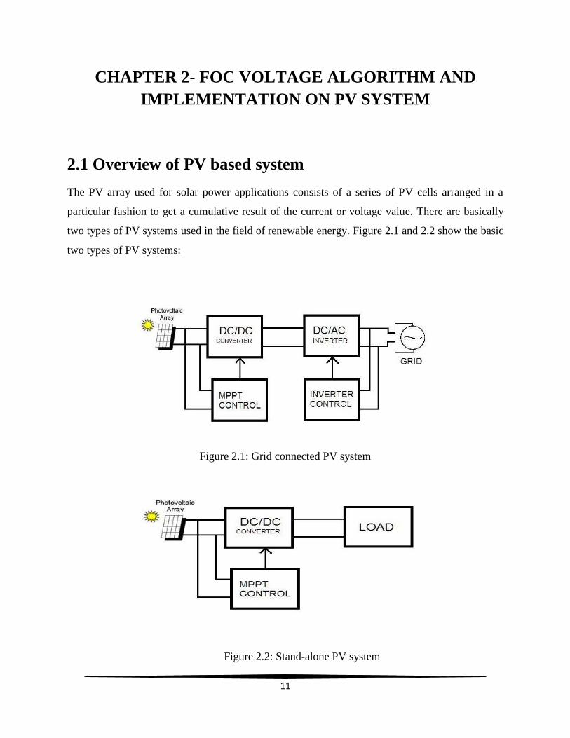
2.1 Overview of PV based system
The PV array used for solar power applications consists of a series of PV cells arranged in a
particular fashion to get a cumulative result of the current or voltage value. There are basically
two types of PV systems used in the field of renewable energy. Figure 2.1 and 2.2 show the basic
two types of PV systems:
Figure 2.1: Grid connected PV system
Figure 2.2: Stand-alone PV system
12
The output power obtained from the PV array, has an efficiency of 6-8%. At such efficiency, it is
not possible to use such energy effectively. So, we have to interconnect other components to get
the power more efficiently and effectively. And further improvement of efficiency can be done
by going for this maximum power point tracking. The basic components which are added are:
1. PV CELL
2. BOOST CONVERTER AS LOAD
3. MICROCONTROLLER
2.1.1 PV CELL
A photovoltaic cell also termed as solar cell is an electrical device that transforms the light
energy straight into the form of electric voltage and current by the photovoltaic effect delivering
power at the output end. It is an arrangement of photoelectric cell which, when exposed to light,
can produce and support a flow of electric current and a generation of voltage without being
involved with any exterior voltage source, but do need an outside load for energy consumption.
The electrical characteristics of PV cell like voltage, current and resistance change when light is
emitted upon it. The output obtained from the panel is variable DC voltage; this voltage depends
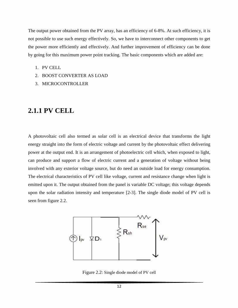
upon the solar radiation intensity and temperature [2-3]. The single diode model of PV cell is
seen from figure 2.2.
Figure 2.2: Single diode model of PV cell
13
2.1.2 BOOST CONVERTER
A step-up converter which we generally come across in Power Electronics is the boost converter
which is actually a DC to DC power converter. This converter has a voltage at the output side
greater than the voltage at the input side. It is a type of switched mode power supply (SMPS) that
comprises two switches of semiconductor type (a transistor and a diode) and a component to
store the output energy, an inductor, a capacitor, or a series or a parallel combination of the two.
The filters used are designed using the capacitors or at times in grouping with the inductors are
usually summed to the converter’s output in order to decrease the ripples in the output voltage.
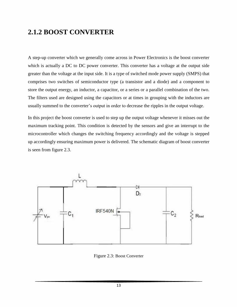
In this project the boost converter is used to step up the output voltage whenever it misses out the
maximum tracking point. This condition is detected by the sensors and give an interrupt to the
microcontroller which changes the switching frequency accordingly and the voltage is stepped
up accordingly ensuring maximum power is delivered. The schematic diagram of boost converter
is seen from figure 2.3.
Figure 2.3: Boost Converter
14
2.1.3 MICROCONTROLLER
A microcontroller is a computer with most of the necessary support chips onboard [11]. It
consists of the following parts:
A CPU (central processing unit) which ‘executes’ various codes and programs.
Some RAM (random-access memory) where it stores variable information.
Some ROM (read only memory) where programs are compiled and are stored.
I/O (Input and output) ports which enable communication with the external world i.e.
linking with the components like mouse, keyboard, monitors and additional peripherals.
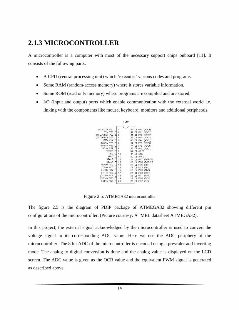
Figure 2.5: ATMEGA32 microcontroller
The figure 2.5 is the diagram of PDIP package of ATMEGA32 showing different pin
configurations of the microcontroller. (Picture courtesy: ATMEL datasheet ATMEGA32).
In this project, the external signal acknowledged by the microcontroller is used to convert the
voltage signal to its corresponding ADC value. Here we use the ADC periphery of the
microcontroller. The 8 bit ADC of the microcontroller is encoded using a prescaler and inverting
mode. The analog to digital conversion is done and the analog value is displayed on the LCD
screen. The ADC value is given as the OCR value and the equivalent PWM signal is generated
as described above.
15
Some of the concepts and peripheries of ATMEGA32 were used while the programming the
FOC voltage algorithm. Those are:
1. PWM and DPWM
2. Interrupt
3. ADC
2.1.3.1 PWM and DPWM
DPWM or Digital Pulse Width Modulation is a modulation process that checks the width of the
pulse, mainly the pulse duration, centered on modulator signal information.
In this project we generate a signal of a definite pulse for the switching of the Boost Converter
for PV applications. The width of the pulse is decided by the voltage and current values we get
from the sensors connected to the array of PV cells. The generation of this PWM wave in digital
platform is carried out by using a signal called Interrupt which alarms if any change in the value
of the voltage is observed.
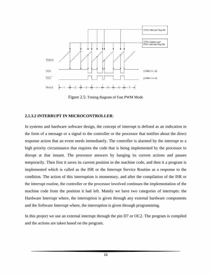
PWM is the pulse width modulation. The fast PWM mode provides a PWM waveform
generation with high frequency. The counter starts counting from the 0 to 255(for 8-bit mode in
this case, where 255=28) and now resumes from 0. In the mode called as the non-inverting
Compare Output mode, the Output Compare Register OC1A is cleared to 0 when there is a
match of TCNT2 with OCR2, and set back to 0. In inverting Compare Output mode, the reverse
thing happens, i.e. the output voltage is made High (1) when compared and then made to 0. Due
to these operations, that are the single-slope operations, the operational frequency of the fast
pulse width modulation mode can be double of the phase correct pulse width modulation mode
which uses the dual-slope operation. This high frequency mode operation factor makes the fast
PWM mode well appropriate for power rectification, regulation, and DAC applications. High
frequency allows physically small sized external components (coils, capacitors), and therefore
reduces total system cost [6].
16
Figure 2.5: Timing diagram of Fast PWM Mode
2.1.3.2 INTERRUPT IN MICROCONTROLLER:
In systems and hardware software design, the concept of interrupt is defined as an indication in
the form of a message or a signal to the controller or the processor that notifies about the direct
response action that an event needs immediately. The controller is alarmed by the interrupt to a
high priority circumstance that requires the code that is being implemented by the processor to
disrupt at that instant. The processor answers by hanging its current actions and pauses
temporarily. Then first it saves its current position in the machine code, and then it a program is
implemented which is called as the ISR or the Interrupt Service Routine as a response to the
condition. The action of this interruption is momentary, and after the compilation of the ISR or
the interrupt routine, the controller or the processor involved continues the implementation of the
machine code from the position it had left. Mainly we have two categories of interrupts: the
Hardware Interrupt where, the interruption is given through any external hardware components
and the Software Interrupt where, the interruption is given through programming.
In this project we use an external interrupt through the pin D7 or OC2. The program is compiled
and the actions are taken based on the program.
17
2.1.3.3 ADC
ADC or Analog to Digital conversion is a method of conversion of analog data to digital data by
sampling and holding technique. By this periphery of microcontroller we can access any analog
data from the external, analyze it by converting into the digital data and sending an output signal
depending upon the results of the analysis.
The ATmega32 has a feature of 10-bit successive approximation ADC [6]. The ADC is linked to
an Analog Multiplexer of 8-channel which can allow 8 single-ended input voltage assembled
from the Port A pins. The input from PORTA is accessed, converted to digital data, analyzed and
output signal is given.
2.2 MPPT:
MPPT or Maximum power point tracking is actually defined as the method that the inverters
linked in grids, battery chargers powered by solar energy and similar type of devices use so as to
achieve the maximum possible conceivable power from the inter linked PV or solar powered
devices, though the transmission system which is mainly optical power type system. The Open
circuit voltage of the PV panel has a complex relationship between solar radiation, total
resistance and temperature that gives out an efficiency which is of non-linear type depends on
the P-V or the I-V curve characteristics. It is the sole resolve of this maximum power point
tracking technique is that, the voltage and current output from the solar cell should be sampled
and the appropriate load (resistance) should be applied at the output side so that we can conceive
the maximum attainable power under any type of conditions with different solar radiation and
temperature. The devices designed for maximum power point are characteristically incorporated
into arrangement that has a converter which converts an electric power and delivers the
converted voltage or current, regulates and filters to drive several loads, including motors or
batteries and even power grids.
18
There are various MPPT algorithms and techniques used for PV applications. Some of them are:
1. P&O algorithm
2. Fractional Open Circuit (FOC) voltage algorithm
3. Incremental Conductance (INC) algorithm
4. Incremental Resistance (INR) algorithm
In this project, we have focused our research on the Fractional Open Circuit (FOC) voltage
algorithm and the implementation of this algorithm in ATMEGA32 microcontroller.
2.2.1 FRACTIONAL OPEN CIRCUIT (FOC) VOLTAGE
ALGORITHM
This algorithm is centered on the concept that the voltage of PV generator at the Maximum
Power point which is coarsely linearly proportional to its open-circuit voltage, Voc. The
proportional constant relies on the material and the fabrication know-hows of the solar cells
technology, fill factor and the climatic conditions, mainly,
𝐾1 = 𝑉𝑚𝑝𝑝
𝑉𝑜𝑐
The factor k1 is generally between 0.71 and 0.78 [4-5] therefore VMPP can be calculated by using
above formulae and set as a reference. The flowchart can be seen in figure 2.6.
19
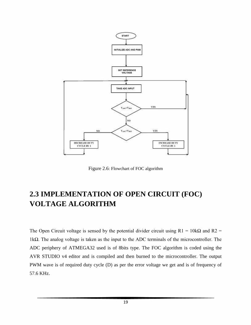
Figure 2.6: Flowchart of FOC algorithm
2.3 IMPLEMENTATION OF OPEN CIRCUIT (FOC)
VOLTAGE ALGORITHM
The Open Circuit voltage is sensed by the potential divider circuit using R1 = 10kΩ and R2 =
1kΩ. The analog voltage is taken as the input to the ADC terminals of the microcontroller. The
ADC periphery of ATMEGA32 used is of 8bits type. The FOC algorithm is coded using the
AVR STUDIO v4 editor and is compiled and then burned to the microcontroller. The output
PWM wave is of required duty cycle (D) as per the error voltage we get and is of frequency of
57.6 KHz.
20
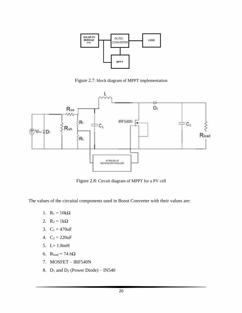
Figure 2.7: block diagram of MPPT implementation
Figure 2.8: Circuit diagram of MPPT for a PV cell
The values of the circuital components used in Boost Converter with their values are:
1. R1 = 10kΩ
2. R2 = 1kΩ
3. C1 = 470uF
4. C2 = 220uF
5. L= 1.8mH
6. Rload = 74.6Ω
7. MOSFET – IRF540N
8. D1 and D2 (Power Diode) – IN540
21
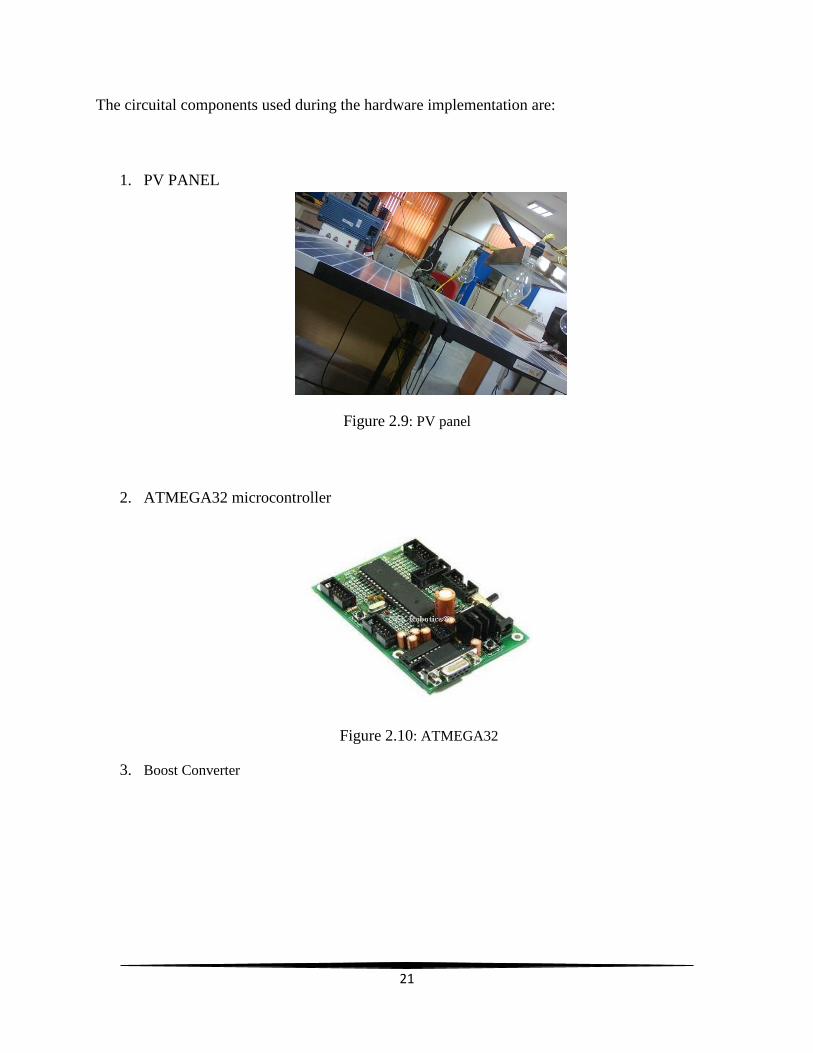
The circuital components used during the hardware implementation are:
1. PV PANEL
Figure 2.9: PV panel
2. ATMEGA32 microcontroller
Figure 2.10: ATMEGA32
3. Boost Converter
22
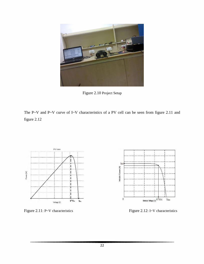
Figure 2.10 Project Setup
The P~V and P~V curve of I~V characteristics of a PV cell can be seen from figure 2.11 and
figure 2.12
Figure 2.11: P~V characteristics Figure 2.12: I~V characteristics
23
CHAPTER 3- RESULTS
The FOC voltage algorithm is implemented on Proteus ISIS v6 and implemented on the PV
panel. The results of the simulation and hardware implementation are discussed.
3.1 SIMULATION RESULTS
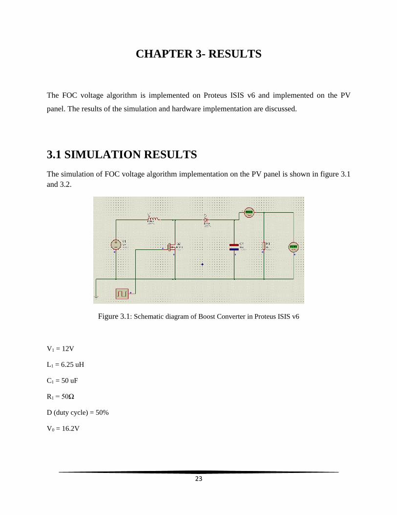
The simulation of FOC voltage algorithm implementation on the PV panel is shown in figure 3.1
and 3.2.
Figure 3.1: Schematic diagram of Boost Converter in Proteus ISIS v6
V1 = 12V
L1 = 6.25 uH
C1 = 50 uF
R1 = 50Ω
D (duty cycle) = 50%
V0 = 16.2V
24
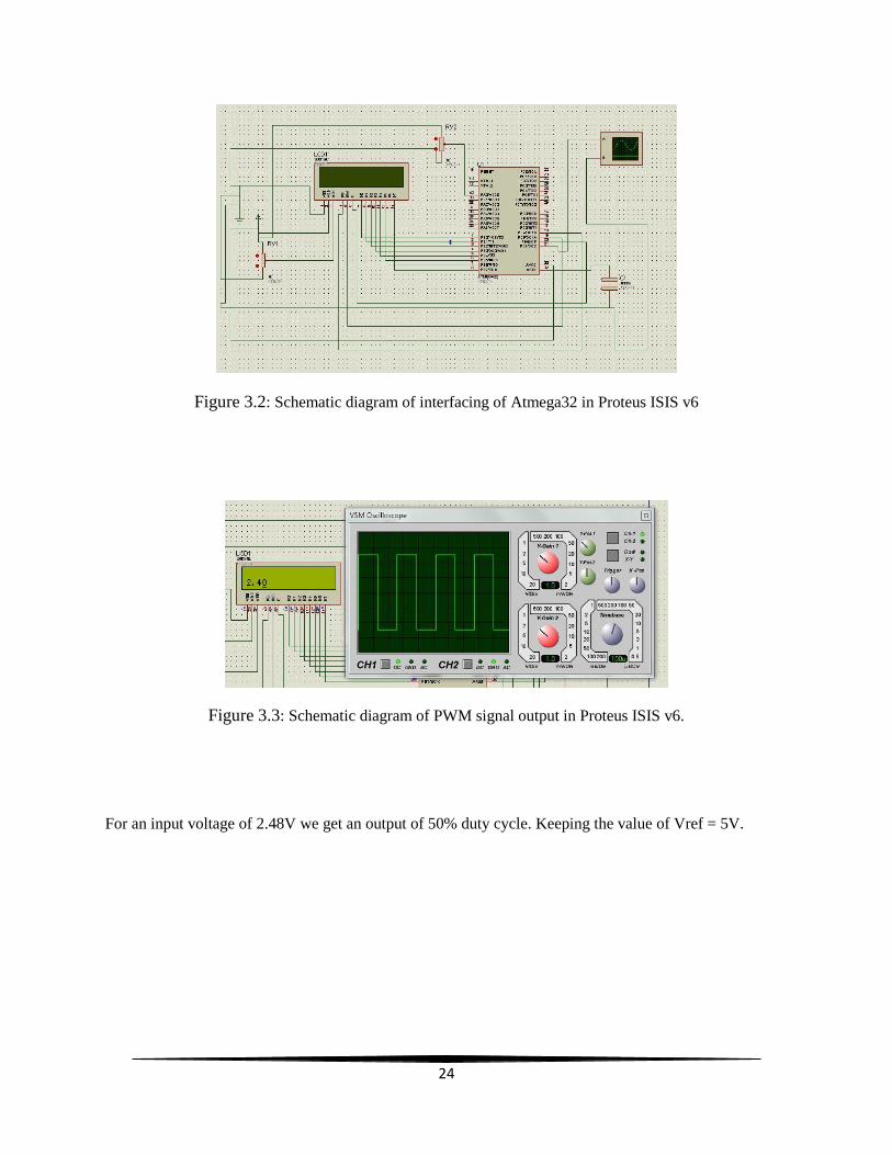
Figure 3.2: Schematic diagram of interfacing of Atmega32 in Proteus ISIS v6
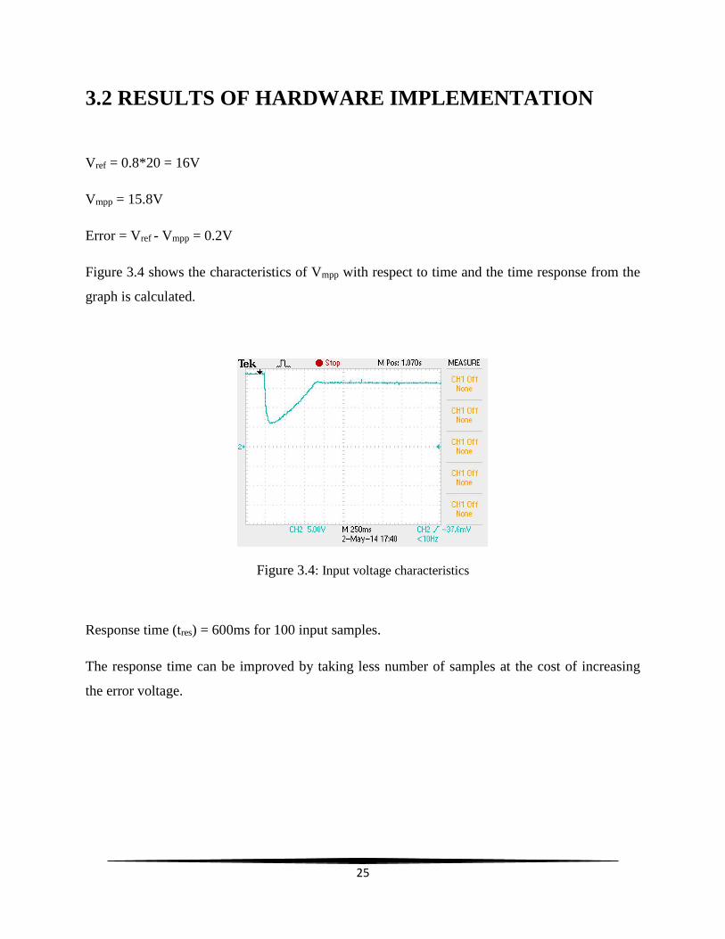
Figure 3.3: Schematic diagram of PWM signal output in Proteus ISIS v6.
For an input voltage of 2.48V we get an output of 50% duty cycle. Keeping the value of Vref = 5V.
25
3.2 RESULTS OF HARDWARE IMPLEMENTATION
Vref = 0.8*20 = 16V
Vmpp = 15.8V
Error = Vref - Vmpp = 0.2V
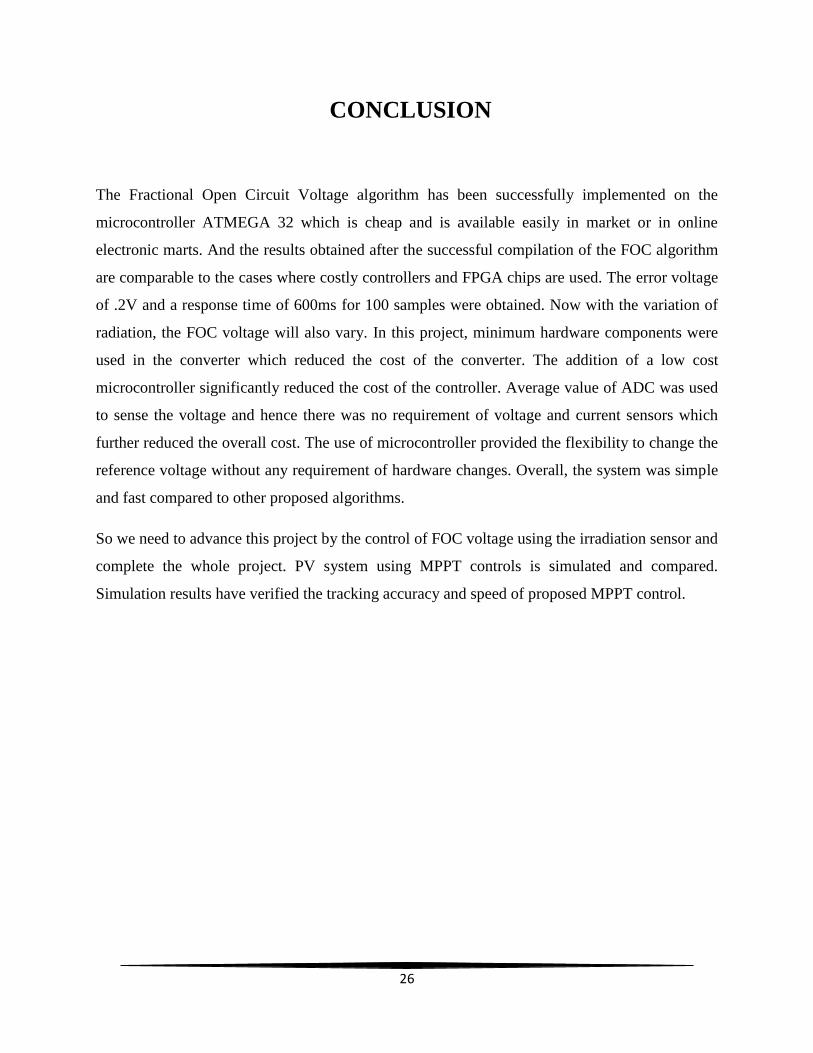
Figure 3.4 shows the characteristics of Vmpp with respect to time and the time response from the
graph is calculated.
Figure 3.4: Input voltage characteristics
Response time (tres) = 600ms for 100 input samples.
The response time can be improved by taking less number of samples at the cost of increasing
the error voltage.
26
CONCLUSION
The Fractional Open Circuit Voltage algorithm has been successfully implemented on the
microcontroller ATMEGA 32 which is cheap and is available easily in market or in online
electronic marts. And the results obtained after the successful compilation of the FOC algorithm
are comparable to the cases where costly controllers and FPGA chips are used. The error voltage
of .2V and a response time of 600ms for 100 samples were obtained. Now with the variation of
radiation, the FOC voltage will also vary. In this project, minimum hardware components were
used in the converter which reduced the cost of the converter. The addition of a low cost
microcontroller significantly reduced the cost of the controller. Average value of ADC was used
to sense the voltage and hence there was no requirement of voltage and current sensors which
further reduced the overall cost. The use of microcontroller provided the flexibility to change the
reference voltage without any requirement of hardware changes. Overall, the system was simple
and fast compared to other proposed algorithms.
So we need to advance this project by the control of FOC voltage using the irradiation sensor and
complete the whole project. PV system using MPPT controls is simulated and compared.
Simulation results have verified the tracking accuracy and speed of proposed MPPT control.
27
REFERENCES
[1] G.Vachtsevanos and K.Kalaitzakis, "A hybrid photovoltaic simulator for utility interactive
studies," IEEE Trans. Energy Conv., vol. EC-2, pp.227-23I, June 1987.
[2] O.Wasynczuk, "Dynamic behavior of a class of photovoltaic power systems," IEEE Trans.
Power App. Syst., vol. 102, pp. 3031-3037, Sept. 1983.
[3] Mukund R. Patel, Ph.D., P.E. (U.S. Merchant Marine Academy Kings Point, New
York)Wind and Solar Power Systems pp.18- 20,34.
[4] T.Esram, and P.L. Chapman, "Comparison of photovoltaic array maximum power point
tracking techniques," IEEE Transactions on Energy Conversion, 22 (2), 439-449, 2007.
[5] Abraham .r. Pressman, "Switching power supply design", Tata McGraw-Hill publications,
1991.
[6] ATMEGA32 microcontroller from ATMEL family, http://www.atmel.in/Images/doc2503.pdf
[7] http://en.wikipedia.org/wiki/Maximum_power_point_tracking#Incremental_conductance
[8] Mummadi Veerachary, "Control of TI-SEPIC converter for optimal utilization of PV power",
IICPE, 2010 New Delhi.
[9] P. S. Revankar, W. Z. Gandhare and A. G. Thosar, Government College of Engineering,
Aurangabad, “Maximum power point tracking for PV systems using MATLAB/SIMULINK”,
2010 Second International Conference on Machine Learning and Computing.
[10] Ramos Hernanz, JA., Campayo Martin, J.J. Zamora Belver, I., Larraga Lesaka, J., Zulueta
Guerrero, E. Puelles PÃrez, E.,” Modeling of photovoltaic module” , International Conference
on Renewable Energies and Power Quality (ICREPQ 2010), Granada (Spain), March 2010.
[11] 8051 Microcontroller- An application based introduction by Chris Braithwaite, Fred Cowan,
Hassan Parchizadeh.