implementing a universal gate set on a logical qubit ... a universal gate set on a logical qubit...
TRANSCRIPT

Implementing a Universal Gate Set on a Logical Qubit Encoded in an Oscillator
Reinier W. Heeres,1, ∗ Philip Reinhold,1, ∗ Nissim Ofek,1 LuigiFrunzio,1 Liang Jiang,1 Michel H. Devoret,1 and Robert J. Schoelkopf1
1Departments of Physics and Applied Physics, Yale University, New Haven, Connecticut 06520, USA
A logical qubit is a two-dimensional subspace ofa higher dimensional system, chosen such that it ispossible to detect and correct the occurrence of cer-tain errors [1]. Manipulation of the encoded infor-mation generally requires arbitrary and precise con-trol over the entire system [2, 3]. Whether based onmultiple physical qubits or larger dimensional modessuch as oscillators, the individual elements in realisticdevices will always have residual interactions whichmust be accounted for when designing logical opera-tions. Here we demonstrate a holistic control strategywhich exploits accurate knowledge of the Hamiltonianto manipulate a coupled oscillator-transmon system.We use this approach to realize high-fidelity (99%, in-ferred), decoherence-limited operations on a logicalqubit encoded in a superconducting cavity resonatorusing four-component cat states [4, 5]. Our resultsshow the power of applying numerical techniques [6]to control linear oscillators and pave the way for utiliz-ing their large Hilbert space as a resource in quantuminformation processing.
Quantum error correction (QEC) aims at the creation oflogical qubits whose information storage and processing ca-pabilities exceed those of its constituent parts. Significantprogress has been made toward quantum state preservationby repeated error detection using stabilizer measurements intrapped ions [3, 7], nitrogen vacancy centers [8], and super-conducting circuits [9–11]. In order to go beyond storage andto manipulate the encoded information, one must performoperations on the whole system in such a way that it results inthe desired transformation within the two-dimensional sub-space defining the logical qubit. Any encoding scheme willconsist of multiple interacting components where the sys-tem dynamics are not naturally confined within the logicalsubspace. Therefore, implementing operations requires care-fully tailored controls which address each component of thesystem and manage their mutual interactions. Recent effortshave achieved this level of control and have demonstratedoperations on a 5 qubit code in nuclear spin ensembles [2]and a 7 qubit code in trapped ions [3].
An alternative to logical qubit implementations based onmultiple two level systems is to encode quantum informa-tion in continuous variable systems or oscillators, for which
∗ [email protected]; These authors contributed equally
there are several schemes [12, 13]. In particular so called“cat states”, which are superpositions of coherent states, canbe used as the logical states of an encoded qubit [4]. Theyare attractive because coherent states are eigenstates of thephoton annihilation operator (a) and therefore single-photonloss induces simple, tractable errors.
Replacing several two level systems by an oscillator dras-tically reduces the hardware cost and complexity by requir-ing fewer components to fabricate and manipulate. How-ever, introducing higher dimensional modes raises the issueof how to realize complete control over the system. Driv-ing an isolated harmonic oscillator results in a displace-ment operation, which can only produce coherent statesfrom the vacuum. Any oscillator-based logical qubit schemewill require a richer class of operations, which one can ac-cess via coupling to a nonlinear system. In the case of afrequency-tunable qubit coupled to an oscillator with theJaynes-Cummings (JC) interaction (HJC = σ+a + σ−a†), ithas been demonstrated that it is possible to prepare arbitrarystates in the oscillator [14, 15].
In the far off-resonant case, where the JC interaction re-duces to the dispersive Hamiltonian (Hd/~ = χa†a|e〉〈e|),a small set of operations acting on a timescale of 2π/χ isin principle sufficient for universal control [16, 17] and hasbeen used for non-trivial operations [18, 19]. Generally,however, any approach decomposing an arbitrary operationinto a sequence of elementary gates generates only a smallsubset of physically allowed control fields. It therefore suf-fers from two issues limiting the achievable fidelity. First,the constructed sequences may require an unacceptably largenumber of gates, limiting operations which are feasible in thepresence of decoherence. Second, the idealized model usedby a constructive approach typically fails to account for theexistence of higher order Hamiltonian terms such as the Kerrnon-linearity HKerr/~ = K
2
(a†
)2a2 and spurious residual cou-
plings in multi-qubit systems.In this work we address these problems by considering a
full model of the time dependent Hamiltonian in the presenceof arbitrary control fields. Nuclear magnetic resonance ex-periments have shown that, if the available controls are uni-versal, numerical optimization procedures can reliably solvethe inversion problem of finding control fields to implementan intended operation. These optimal control algorithms,in particular the Gradient Ascent Pulse Engineering (grape)method [6, 20], have been successfully employed in a varietyof other fields [21, 22]. Since grape crucially depends on the
arX
iv:1
608.
0243
0v1
[qu
ant-
ph]
8 A
ug 2
016

2
a b c
FIG. 1. Experimental system and demonstration of control strategy. a, Schematic drawing of the experimental system. A λ/4 coax-stubcavity resonator is coupled to a transmon and readout resonator on a sapphire substrate. Input couplers close to the transmon and cavitydeliver the respective time-dependent microwave control fields εT (t) and εC(t). b, Lower panel: optimized transmon and oscillator controlwaveforms of length approximately 2π/χ to take the oscillator from vacuum to the 6-photon Fock state. Solid (dotted) lines represent thein-phase (quadrature) field component. Upper panel: oscillator photon-number population trajectory versus time conditioned on transmonin |g〉. A complex trajectory occupying a wide range of photon numbers is taken to perform the intended operation. c, Characterizationof the oscillator state using Wigner tomography (bottom) and transmon spectroscopy (top), where grey dashed lines indicate the transitionfrequency associated with the first 7 Fock states. The single peak in the spectroscopy data directly reveals the oscillator’s population due tothe dispersive interaction giving a frequency shift of 6χ/2π ≈ 13 MHz.
model of the system, its successful application is powerfulevidence that the Hamiltonian used accurately captures thesystem dynamics over a broad range of driving conditions.
The physical system used in our experiments is schemat-ically depicted in Fig. 1a. The seamless aluminum λ/4coax-stub cavity resonator [23] with a fundamental fre-quency 4452.6 MHz has an energy relaxation time of2.7 ms. A single-junction transmon with transition frequency5664.0 MHz and anharmonicity of 236 MHz is dispersivelycoupled to the oscillator, resulting in an interaction termχa†a|e〉〈e|, with χ/2π = −2.2 MHz. Crucially, additionalhigher order terms are determined accurately through a sep-arate set of calibration experiments (Table SI, Supplemen-tary Information). Control of the system is implementedthrough full in-phase/quadrature (IQ) modulated microwavefields centered on the transmon (oscillator) frequency andsent to the pin coupling to the transmon (oscillator) mode.In the rotating wave approximation, this results in the driveHamiltonian Hc/~ = εCa + εTσ− + h.c. Modulation using anarbitrary waveform generator allows the coefficients εC andεT to be arbitrary complex-valued functions of time.
As an example application of grape to our system, we findεC(t) and εT (t) such that, starting from the vacuum, after 500ns of driven evolution the system ends up in the state |g, 6〉(Fig. 1bc). This highly nontrivial operation, effectively real-izing a |6〉〈0| coupling term on the oscillator, is enabled bythe dispersive Hamiltonian using only linear drives on thetransmon and the oscillator.
Using this control strategy, we can target the creation andmanipulation of a logical qubit encoded in an even-parityfour-component cat subspace. Omitting normalization, the
code states in this subspace can be written as
|±ZL〉 = |α〉 + |−α〉 ± |iα〉 ± |−iα〉 (1)
where we use α =√
3. These code words are both of evenphoton number parity, and are distinguished by their photonnumber modulo 4:
|+ZL〉 =∑
n
α4n
√(4n)!
|4n〉 (2)
|−ZL〉 =∑
n
α4n+2
√(4n + 2)!
|4n + 2〉 (3)
Single photon loss, the dominant error channel for the sys-tem, transforms both code words to states of odd photonnumber parity. The encoded information, however, is pre-served by this process as long as one can keep track of thenumber of photons that have been lost. Since parity mea-surements can be performed efficiently and non-destructively[24], single photon loss is a correctable error [5].
Using grape, we create a universal set of gates on ourlogical qubit, which includes X and Y rotations by π andπ/2, as well as Hadamard and T gates. These pulses areeach 1100 ns ≈ 2.4 × 2π/χ in length with a 2 ns time res-olution, although 99% of the spectral content lies within abandwidth of 33 MHz (27 MHz) for the transmon (oscilla-tor) drive (Fig. S2, Supplementary Information). Each op-eration is designed to begin and end with the transmon inthe ground state. Additionally, we create encode (Uenc) anddecode (Udec) pulses to transfer a bit of quantum informa-tion between our transmon |g, 0〉, |e, 0〉 subspace, which we

3
a
b
c
d
T
C
FIG. 2. Characterization of encoded states. a, Uenc and Udec are operations which coherently map between two distinct two-dimensionalsubspaces, represented by Bloch spheres. The first subspace consists of the transmon |g〉 and |e〉 levels, with the oscillator in the vacuum.The second is given by the oscillator-encoded states |+ZL〉 and |−ZL〉 (Eq. 1), with the transmon in the ground state. b, Wigner tomographysequence which characterizes the encoded states. A transmon state is prepared by applying an initial rotation Ui and is mapped to theoscillator using Uenc. An oscillator displacement Dβ followed by a parity mapping operation Π (implemented using an optimal controlpulse) allows one to measure the oscillator Wigner function W(β). The transmon can be re-used to measure the oscillator’s parity becausethe encoding pulse leaves the transmon in the ground state with high probability (p > 98%). c, Applying Uenc to the transmon states |g〉and |e〉 produces states whose Wigner functions are consistent with the intended encoded basis states (Eq. 1). A transmon spectroscopyexperiment (top panel) illustrates that only photon number states with n = 0 mod 4 and n = 2 mod 4 are present for logical state |+ZL〉 and|−ZL〉 respectively. d, Applying Uenc to superpositions of the transmon basis states demonstrates that the relative phase is preserved and thatUenc is a faithful map between the transmon and logical qubit Bloch spheres. These states, on the equator of the Bloch sphere, are equallyweighted superpositions of |+ZL〉 and |−ZL〉 and therefore contain all even photon numbers present in the basis states.
can easily prepare and measure, and our encoded subspace|g,+ZL〉, |g,−ZL〉 (Fig. 2a).
We characterize the encode operation by preparing all 6cardinal points on the transmon Bloch sphere, applying theencode pulse and performing Wigner tomography on theoscillator (Fig. 2b–d). Maximum likelihood reconstructionof the density matrix associated with the measured Wignerfunctions indicates an average fidelity of 0.96. This metricunderestimates the fidelity of Uenc because it is affected byseveral sources of error not intrinsic to the encoding oper-ation itself, including error in the parity mapping and mea-surement infidelity.
Process tomography provides a full characterization of a
quantum operation, but depends on pre-existing trusted op-erations and measurements which are not available for ourencoded subspace. However, an indirect characterization ofa gate UX on our logical qubit can be performed using the op-eration UdecUXUenc, which maps the transmon subspace ontoitself. This allows one to use the trusted state preparationsand measurements on the transmon to perform tomographyon the composite process (Fig. 3a). The reconstructed pro-cess matrices show qualitative agreement with the intendedencoded qubit gates. We can break the calculated infidelitydown into 3 parts: transmon preparation and measurementerror, encode-decode error and gate error. Using the experi-mentally determined process fidelities both without any op-

4
T
Cb
a
FIG. 3. Process tomography of operations on encoded qubit. a,In order to characterize a gate UX on the encoded qubit, transmonprocess tomography is performed on the operation UdecUXUenc.Process tomography is implemented by performing an initial trans-mon rotation Ui right after state preparation, as well as a final trans-mon rotation U f , right before measurement of the transmon. b,Process tomography results for selected operations (for additionaloperations, see Fig. S7, Supplementary Information). The processtomography yields an estimated quantum channel G. We repre-sent this channel in the Pauli transfer representation. The bar la-beled with operators AB represents Tr (AG(B)) /2. Red and pinkbars indicate the experimental and ideal values, respectively. Theinfidelity ∆FPT of operation UX is estimated as the difference be-tween FPT(UdecUXUenc) and FPT(UdecUenc) = 0.964. The selectedset of operations, X180, X90,Y90,T , allows universal control ofthe logical qubit.
eration FPT(No Op.) = 0.982, as well as with the encode anddecode pulses FPT(UdecUenc) = 0.964, we estimate an in-fidelity contribution of approximately 1.8% for each of thefirst two components. To account for these factors to firstorder, the infidelity of operations on the encoded qubit arereported relative to FPT(UdecUenc). We find an average infi-delity of 0.75% over our set of 9 gates (Table I).
In order to establish the fidelity of this set of operationsmore accurately, we perform randomized benchmarking [25](RB) on our encoded qubit (Fig. 4a). From the resulting data(Fig. 4c) we infer an average gate fidelity of 0.991. The in-fidelity of each of the individual gates is isolated using in-terleaved randomized benchmarking [26] (iRB), which alter-nates between a single fixed and a random gate (Fig. 4b).Comparing the fitted decay constants of the RB and iRB re-
Gate 1 − FRB (%) ∆FPT (%) 1 − Fsim (%)I 0.46 ± 0.02 0.51 0.31X90 0.79 ± 0.02 0.57 0.78-X90 0.91 ± 0.03 0.71 0.83X180 1.11 ± 0.03 0.88 1.09Y90 0.96 ± 0.03 0.98 0.76-Y90 0.81 ± 0.02 0.52 0.75Y180 1.28 ± 0.03 0.99 1.67H 0.93 ± 0.03 0.86 1.00average 0.90 ± 0.02 0.75 0.90UencUdec 1.70 ± 0.03 1.39 1.76T - 0.71 0.40
TABLE I. Operation fidelities. Measured and simulated gateinfidelities. All fidelities reported are average gate fidelitiesF (E1,E2) ≡
∫dψF(E1(ψ),E2(ψ)), where F is the usual quantum
state fidelity F(ρ1, ρ2) = Tr(√ρ1ρ2
√ρ1). FRB, ∆FPT and Fsim are
the values extracted from interleaved randomized benchmarking,process tomography (see Fig. 3) and simulations using the Lind-blad master equation respectively. The row labeled “average” givesthe fidelities averaged over the first 8 gates, which is the set used inthe standard randomized benchmarking experiment.
sults allows us to extract the fidelity of the fixed gate. Theresults are summarized in Table I, together with the gate fi-delities based on process tomography (Fig. 3) and Lindbladmaster equation simulations accounting for finite T1 and T2of the transmon and oscillator (see Supplementary Informa-tion). We note that all gates are implemented with an approx-imately equal infidelity of 1% and that process tomographyand iRB yield consistent results. While several sources ofdecoherence are accounted for in the master equation simula-tions, the dominant source of infidelity in the model is trans-mon dephasing (T2 ≈ 43 µs). The strong agreement betweensimulations and experiment indicates that the infidelity is pri-marily caused by decoherence and that additional contribu-tions associated with imperfections in the model Hamilto-nian and the applied pulses are a significantly smaller effect.
In conclusion, we have demonstrated a high-fidelity im-plementation of a universal set of gates on a qubit encodedinto an oscillator using the cat-code. The low error rates forthese operations are verified using both process tomographyand randomized benchmarking, and the results are consis-tent with simulations which account for decoherence. Weobtained these operations by numerically optimizing time-dependent drives which make use of the well-characterizeddispersive interaction between the far detuned oscillator andtransmon modes. While in this Letter we have focused onrealizing and characterizing single-qubit operations on cat-encoded qubits, this control technique is not restricted tothese goals, and is in principle capable of crafting arbi-trary unitary operations on the transmon-oscillator system.The high quality of these operations depends critically on

5
T
C
T
C
a
b
c
FIG. 4. Randomized benchmarking of operations on encoded qubit. a, Randomized benchmarking (RB) sequence. In RB a sequence ofClifford operations of length n is chosen at random (UX,Y,...), followed by the operation which inverts the effect of the sequence (Ucorr). Inorder to apply this technique to the operations on the encoded qubit, we begin the experiment by encoding, and decode before measurement.Our implementation of RB creates a new random gate sequence for every measurement, and is thus not biased by the distribution ofsequences which are measured. b, Interleaved randomized benchmarking (iRB) sequence: In order to establish the fidelity of a singleoperation (here, UX), the operation is interleaved with random operations, and the benchmarking result is compared with the non-interleavedcase. c, The probability of measuring the correct result versus sequence length n is fit to a two parameter model pcorrect = 0.5 + Ae−n/τ.The lower panel shows the fit residuals. Each data point is the result of 2000 averages, with a new sequence realization every shot. Theerror averaged over all gates is computed as r = (1 − e−1/τ(RB))/2 [25]. The average error for a single gate X is computed as r(X) =
(1 − e1/τ(X)−1/τ(RB))/2 [26].
an accurate characterization of the system Hamiltonian, anddemonstrates the utility of numerical optimal control for re-alizing quantum information processing.
I. ACKNOWLEDGMENTS
We would like to thank Katrina Sliwa and Michael Ha-tridge for providing the parametric amplifier, Chris Axline,Jacob Blumoff, Kevin Chou and Chen Wang for discussions
regarding sample design, Stefan Krastanov, Chao Shen andVictor Albert for discussions on universal control and SteveFlammia and Robin Blume-Kohout for advice about tomog-raphy. This research was supported by the U.S. Army Re-search Office (W911NF-14-1-011). P.R. was supported bythe U.S. Air Force Office of Scientific Research (FA9550-15-1-0015), L.J. by the Alfred P. Sloan Foundation and thePackard Foundation. Facilities use was supported by theYale Institute for Nanoscience and Quantum Engineering(YINQE), the Yale SEAS cleanroom, and the National Sci-ence Foundation (MRSECDMR-1119826).
[1] Barbara M Terhal. Quantum error correction for quantummemories. Rev. Mod. Phys., 87(2):307–346, April 2015.
[2] Jingfu Zhang, Raymond Laflamme, and Dieter Suter. Experi-mental Implementation of Encoded Logical Qubit Operationsin a Perfect Quantum Error Correcting Code. Phys. Rev. Lett.,109(10):100503, September 2012.
[3] D Nigg, M Muller, E A Martinez, P Schindler, M Hen-nrich, T Monz, M A Martin-Delgado, and R Blatt. Quan-tum computations on a topologically encoded qubit. Science,345(6194):302–305, July 2014.
[4] Mazyar Mirrahimi, Zaki Leghtas, Victor V Albert, StevenTouzard, Robert J Schoelkopf, Liang Jiang, and Michel H De-voret. Dynamically protected cat-qubits: a new paradigm foruniversal quantum computation. New J. Phys., 16(4), 2014.
[5] Nissim Ofek, Andrei Petrenko, Reinier Heeres, Philip Rein-hold, Zaki Leghtas, Brian Vlastakis, Yehan Liu, Luigi Frun-
zio, SM Girvin, Liang Jiang, M Mirrahimi, M H Devoret, andR J Schoelkopf. Extending the lifetime of a quantum bit witherror correction in superconducting circuits. Nature, advanceonline publication, Jul 2016.
[6] Navin Khaneja, Timo Reiss, Cindie Kehlet, Thomas Schulte-Herbruggen, and Steffen J Glaser. Optimal control of coupledspin dynamics: design of NMR pulse sequences by gradientascent algorithms. J. Mag. Res., 172(2):296–305, February2005.
[7] J Chiaverini, D Leibfried, T Schaetz, MD Barrett,RB Blakestad, J Britton, WM Itano, JD Jost, E Knill,C Langer, et al. Realization of quantum error correction. Na-ture, 432(7017):602–605, 2004.
[8] J Cramer, N Kalb, M A Rol, B Hensen, M S Blok,M Markham, D J Twitchen, R Hanson, and T H Taminiau.Repeated quantum error correction on a continuously en-
6
coded qubit by real-time feedback. Nature Communications,7:11526, May 2016.
[9] J Kelly, R Barends, Austin G Fowler, A Megrant, E Jeffrey,T C White, D Sank, J Y Mutus, B Campbell, Yu Chen, Z Chen,B Chiaro, A Dunsworth, I C Hoi, C Neill, P J J O’Malley,C Quintana, P Roushan, A Vainsencher, J Wenner, Andrew NCleland, and John M Martinis. State preservation by repetitiveerror detection in a superconducting quantum circuit. Nature,519(7541):66–69, March 2015.
[10] D Riste, S Poletto, M Z Huang, A Bruno, V Vesterinen, O PSaira, and L DiCarlo. Detecting bit-flip errors in a logicalqubit using stabilizer measurements. Nature Communications,6:6983, April 2015.
[11] A D Corcoles, Easwar Magesan, Srikanth J Srinivasan, An-drew W Cross, M Steffen, Jay M Gambetta, and Jerry MChow. Demonstration of a quantum error detection code us-ing a square lattice of four superconducting qubits. NatureCommunications, 6:6979, April 2015.
[12] Daniel Gottesman, Alexei Kitaev, and John Preskill. Encodinga qubit in an oscillator. Phys. Rev. A, 64(1):012310, June 2001.
[13] Marios H Michael, Matti Silveri, R T Brierley, Victor V Al-bert, Juha Salmilehto, Liang Jiang, and Steven M Girvin.New Class of Quantum Error-Correcting Codes for a BosonicMode. Phys. Rev. X, 6(3):031006, July 2016.
[14] C K Law and J H Eberly. Arbitrary Control of a QuantumElectromagnetic Field. Phys. Rev. Lett., 76(7):1055–1058,February 1996.
[15] Max Hofheinz, H Wang, M Ansmann, Radoslaw C Bialczak,Erik Lucero, M Neeley, A D O’Connell, D Sank, J Wenner,John M Martinis, and Andrew N Cleland. Synthesizing arbi-trary quantum states in a superconducting resonator. Nature,459(7246):546–549, 2009.
[16] Stefan Krastanov, Victor V Albert, Chao Shen, Chang-LingZou, Reinier W Heeres, Brian Vlastakis, Robert J Schoelkopf,and Liang Jiang. Universal control of an oscillator with disper-sive coupling to a qubit. Phys. Rev. A, 92(4):040303, October2015.
[17] Simon E Nigg. Deterministic Hadamard gate for microwavecat-state qubits in circuit QED. Phys. Rev. A, 89(2):022340,February 2014.
[18] Brian Vlastakis, Gerhard Kirchmair, Zaki Leghtas, Simon ENigg, Luigi Frunzio, Steven M Girvin, Mazyar Mirrahimi,Michel H Devoret, and Robert J Schoelkopf. Determin-istically Encoding Quantum Information Using 100-PhotonSchrodinger Cat States. Science, 342(6158):607–610, Novem-ber 2013.
[19] Reinier W Heeres, Brian Vlastakis, Eric Holland, StefanKrastanov, Victor V Albert, Luigi Frunzio, Liang Jiang,and Robert J Schoelkopf. Cavity State Manipulation Us-ing Photon-Number Selective Phase Gates. Phys. Rev. Lett.,115(13):137002, September 2015.
[20] P de Fouquieres, SG Schirmer, SJ Glaser, and Ilya Kuprov.Second order gradient ascent pulse engineering. J. Mag. Res.,212(2):412–417, 2011.
[21] Florian Dolde, Ville Bergholm, Ya Wang, Ingmar Jakobi,Boris Naydenov, Sebastien Pezzagna, Jan Meijer, FedorJelezko, Philipp Neumann, Thomas Schulte-Herbruggen, Ja-cob Biamonte, and Jorg Wrachtrup. High-fidelity spin entan-glement using optimal control. Nature Communications, 5,
February 2014.[22] B E Anderson, H Sosa-Martinez, C A Riofrıo, Ivan H Deutsch,
and Poul S Jessen. Accurate and Robust Unitary Transfor-mations of a High-Dimensional Quantum System. Phys. Rev.Lett., 114(24):240401, June 2015.
[23] Matthew Reagor, Wolfgang Pfaff, Christopher Axline,Reinier W. Heeres, Nissim Ofek, Katrina Sliwa, Eric Holland,Chen Wang, Jacob Blumoff, Kevin Chou, Michael J. Hatridge,Luigi Frunzio, Michel H. Devoret, Liang Jiang, and Robert J.Schoelkopf. Quantum memory with millisecond coherence incircuit qed. Phys. Rev. B, 94:014506, Jul 2016.
[24] L Sun, A Petrenko, Z Leghtas, B Vlastakis, G Kirch-mair, KM Sliwa, A Narla, M Hatridge, S Shankar, J Blu-moff, L Frunzio, M Mirrahimi, Devoret M H, and R JSchoelkopf. Tracking photon jumps with repeated quantumnon-demolition parity measurements. Nature, 511:444–448,2014.
[25] Easwar Magesan, Jay M Gambetta, and Joseph Emerson.Scalable and Robust Randomized Benchmarking of QuantumProcesses. Phys. Rev. Lett., 106(18):180504, May 2011.
[26] Easwar Magesan, Jay M Gambetta, Blake R Johnson, Colm ARyan, Jerry M Chow, Seth T Merkel, Marcus P da Silva,George A Keefe, Mary B Rothwell, Thomas A Ohki, Mark BKetchen, and M Steffen. Efficient Measurement of QuantumGate Error by Interleaved Randomized Benchmarking. Phys.Rev. Lett., 109(8):080505, August 2012.
[27] Richard H Byrd, Peihuang Lu, Jorge Nocedal, and Ciyou Zhu.A limited memory algorithm for bound constrained optimiza-tion. SIAM Journal on Scientific Computing, 16(5):1190–1208, 1995.
[28] I Najfeld and T F Havel. Derivatives of the Matrix Exponentialand Their Computation. Advances in Applied Mathematics,16(3):321–375, September 1995.
[29] F Motzoi, Jay M Gambetta, S T Merkel, and F K Wilhelm.Optimal control methods for rapidly time-varying Hamiltoni-ans. Phys. Rev. A, 84(2):022307, August 2011.
[30] D J Egger and F K Wilhelm. Adaptive Hybrid Optimal Quan-tum Control for Imprecisely Characterized Systems. Phys.Rev. Lett., 112(24):240503, June 2014.
[31] J Kelly, R Barends, B Campbell, Y Chen, Z Chen, B Chiaro,A Dunsworth, Austin G Fowler, I C Hoi, E Jeffrey, A Megrant,J Mutus, C Neill, P J J O’Malley, C Quintana, P Roushan,D Sank, A Vainsencher, J Wenner, T C White, Andrew NCleland, and John M Martinis. Optimal Quantum Con-trol Using Randomized Benchmarking. Phys. Rev. Lett.,112(24):240504, June 2014.
[32] Gerhard Kirchmair, Brian Vlastakis, Zaki Leghtas, Simon ENigg, Hanhee Paik, Eran Ginossar, Mazyar Mirrahimi, LuigiFrunzio, Steven M Girvin, and Robert J Schoelkopf. Obser-vation of quantum state collapse and revival due to the single-photon kerr effect. Nature, 495(7440):205–209, 2013.

7
System Parameter Hamiltonian Term Parameter ValueTransmon frequency ωT b†b 2π × 5664.0 MHzOscillator frequency ωC a†a 2π × 4452.6 MHzDispersive shift χa†ab†b 2π × −2194 ± 3 kHzTransmon anharmonicity α
2 (b†)2b2 2π × −236 MHzOscillator anharmonicity (Kerr) K
2 (a†)2a2 2π × −3.7 ± 0.1 kHzSecond order dispersive shift χ′
2 (a†)2a2b†b 2π × −19.0 ± 0.4 kHzTransmon relaxation 1
T1D[b] 170 ± 10µs
Transmon dephasing 1Tφ
D[b†b] 43 ± 5µs
Oscillator relaxation 1Tcav
D[a] 2.7 ± 0.1ms
TABLE SI. Measured system parameters The dispersive shift and its second order correction are determined using transmon spectroscopyexperiments (Fig. S1). The oscillator anharmonicity is determined by fitting a set of Wigner functions after different lengths of free evolutiontime.
Supplementary Material
I. SYSTEM HAMILTONIAN
Here we give the full system Hamiltonian to the precision with which we have characterized it. We denote the annihilationoperator corresponding to the oscillator (transmon) mode with a (b). Breaking down the system Hamiltonian into componentsrepresenting the individual modes, their interactions, as well as driving terms, we can write
H(t) = Hoscillator + Htransmon + Hinteraction + Hdrive(t) (4)
Hoscillator/~ = ωC a†a +K2
(a†)2a2 (5)
Htransmon/~ = ωT b†b +α
2(b†)2b2 (6)
Hinteraction/~ = χa†ab†b +χ′
2b†b(a†)2a2 (7)
Hdrive(t)/~ = εC(t)a + εT (t)b + h.c. (8)
When simulating how known decoherence sources should impact the fidelity of our operations, we use a Markovian Lind-blad master equation of the form:
∂
∂tρ(t) =
−i~
[H(t), ρ(t)] +
(1
T1,CD[a] +
1T1,T
D[b] +1
TφD[b†b]
)(ρ(t)) (9)
D[a](ρ) = aρa† −12a†a, ρ (10)
The measured values for each of these system parameters are shown in table SI.
II. GRAPE IMPLEMENTATION
We define operations on our system in terms of a set of simultaneous state transfers, i.e. the operation should, for each i, takethe initial state
∣∣∣ψ(i)init
⟩to the corresponding final state
∣∣∣ψ(i)final
⟩. In order to prepare a desired operation on the joint oscillator-
transmon Hilbert space, we use grape to maximize the (coherent) average fidelity of these state transfers over the controlsε(t) ≡ (εC(t), εT (t)):
maximizeε(t)
F (ε(t)) (11)

8
0 5 10 15Detuning (MHz)
0.1
0.2
0.3
Pe
5 10 15 20 25Detuning (MHz)
10 15 20 25 30 35Detuning (MHz)
5 10 15 20 25Detuning (MHz)
10 15 20 25 30Detuning (MHz)
0 2 4 6 8 10 12 14 16
n
500
0
500
1000
1500
2000
2500f−
2194.4n
(kH
z)19.0n(n−1)/2
FIG. S1. Dispersive shift measurement. The dispersive shift χ and its second order correction term χ′ are determined from transmonspectroscopy experiments with several different displacements (top). Each peak is fit to a Gaussian and the resulting center frequencies arefit using a quadratic model.
F (ε(t)) =
∣∣∣∣∣∣∣∑i
⟨ψ(i)
final
∣∣∣U (T, ε(t))∣∣∣ψ(i)
init
⟩∣∣∣∣∣∣∣2
, (12)
where the unitary U defined by the waveforms ε(t) is given by the time-ordered exponential of the Hamiltonian up to somefinal time T ,
U(T, ε(t)) = T exp(−
∫ T
0dt H (ε(t))
). (13)
To make the problem numerically tractable, ε(t) is represented as a piecewise constant function with N = T/∆t steps of length∆t = 2 ns, corresponding to the time resolution of our arbitrary waveform generator.
U (T, ε(t)) = UNUN−1 · · ·U2U1 (14)
Uk = exp(
i∆t~
H(ε(k∆t))
(15)
Using 4 parameters per time point (real and imaginary components of the oscillator and transmon drives) and N = 550 timepoints representing the 1.1 µs pulse, there are 2200 parameters to optimize over. In order to carry out a numerical optimizationwith such a large number of parameters, it is crucial that one can efficiently calculate the gradient of the optimized functionwith respect to all of its parameters. In this case it is possible to use Quasi-Newton optimization algorithms, such as L-BFGS[27] in order to optimize the function with many fewer function evaluations. We can simplify the calculation of the gradient

9
as follows:
∂F
∂εi(k∆t)= 2
(Re(v)Re
(∂v
∂εi(k∆t)
)+ Im(v)Im
(∂v
∂εi(k∆t)
))(16)
v ≡∑
i
⟨ψ(i)
final
∣∣∣U (T, ε(t))∣∣∣ψ(i)
init
⟩(17)
∂v∂εi(k∆t)
=∑
i
⟨ψ(i)
final
∣∣∣∂U (T, ε(t))∂εi(k∆t)
∣∣∣ψ(i)init
⟩(18)
=∑
i
⟨ψ(i)
final
∣∣∣UN · · ·Uk+1∂Uk
∂εi(k∆t)Uk−1 · · ·U1
∣∣∣ψ(i)init
⟩(19)
Therefore, the calculation of the gradient can be reduced to computing the states Uk−1 · · ·U1∣∣∣ψ(i)
init
⟩, U†k+1 · · ·U
†
N
∣∣∣ψ(i)final
⟩as
well as the gradient of the step propagator ∂Uk∂εi(k∆t) . The states can be stored from the evaluation of the fidelity itself, and there
are several efficient ways of evaluating the gradient of the propagator [28].The optimization problem defined by equation 11 is generally underdetermined, i.e. there are many solutions ε(t) which
achieve equally high fidelities. Therefore, we can add additional terms to the optimization cost function, such that the resultingsolution optimizes against several other desiderata. For a set of constraints on the solution gi ≥ 0, where ideally gi (ε(t)) = 0,we can associate a Lagrange multiplier λi, and modify our optimization to read:
maximizeε(t)
F (ε(t)) −∑
i
λigi (ε(t)) (20)
The values λi are chosen by trial-and-error, set to be just large enough that the violation of the constraint upon termination iswithin acceptable levels. For instance, since the output power of our AWG is limited, the pulse must obey ε(t) ≤ εmax for all t.We can construct a penalty term of the form
gamplitude (ε(t)) =
∫dt (|ε(t)| − εmax)2 Θ (|ε(t)| − εmax) (21)
=∑
n
(|ε(n∆t)| − εmax)2 Θ (|ε(n∆t)| − εmax) (22)
Since the transfer function of the lines between the AWG and the experimental system becomes more and more uncertainas one moves further away from resonance, it is also desirable to minimize the bandwidth of the applied pulses, we do this intwo ways. First, we create a penalty term of the form
gderivative (ε(t)) =
∫dt
(∂ε(t)∂t
)2
(23)
→∑
n
(ε((n + 1)∆t) − ε(n∆t))2 , (24)
where equation 24 is the appropriate equivalent of equation 23 for a piecewise constant function. Additionally, we enforce ahard cutoff on the minimum and maximum frequencies allowed in the solution by reparametrizing the optimization problemin terms of the Fourier transform of the pulses [29]:
maximizeε(ω)
F (ε(t)) −∑
i
λigi (ε(t)) (25)
such that ε(ω) = 0 when ω < ωmin or ω > ωmax
Since computer memory is finite, we are forced to choose a photon number truncation N such that the operator a becomesa N × N matrix. When we do this, we are in effect replacing our infinite-dimensional oscillator with a finite-dimensionalqudit. This replacement is only valid if all of the system dynamics relevant for the desired state transfers occurs within the|0〉, . . . , |N − 1〉 subspace. For generic applied drives this is not the case. In order to enforce this property, we modify the

10
optimization problem to find a solution which operates identically under several different values of N. Writing the fidelity ascomputed with a truncation N as FN , we have:
maximizeε(ω)
∑k
FN+k (ε(t))
− ∑i
λigi (ε(t))
(26)
To enforce that the behavior is identical in the different truncations, we add the penalty term
gdiscrepancy(ε(t)
)=
∑k1,k2
(FN+k1 (ε(t)) − FN+k2 (ε(t))
)2 (27)
The choice of N determines the maximum photon number population which can be populated during the pulse, and figuresin determining the minimum time necessary for the operation (faster pulses can be achieved with higher N).
11
5
5 Encode
0
380
6
6 Decode
0
1000
4
4 X(180)
0
360
6
6Y(180)
0
600
3
3 X(90)
0
260
4
4
Dri
ve S
trength
(M
Hz)
Y(90)
0
200
Pulse
FFT (u
nitle
ss)
3
3 X(-90)
0
240
2
2 Y(-90)
0
200
1
1T
0
100
4
4 H
0
460
0 200 400 600 800 1000Time (ns)
0.5
0.5 I
40 30 20 10 0 10 20 30Frequency (MHz)
0
40
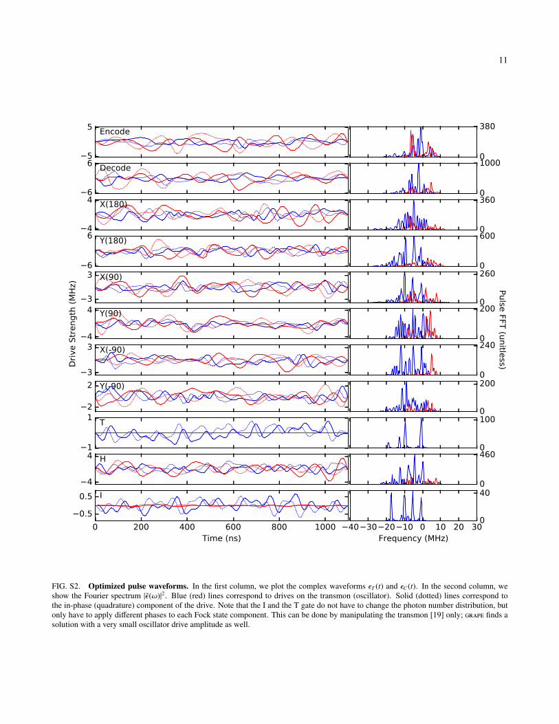
FIG. S2. Optimized pulse waveforms. In the first column, we plot the complex waveforms εT (t) and εC(t). In the second column, weshow the Fourier spectrum |ε(ω)|2. Blue (red) lines correspond to drives on the transmon (oscillator). Solid (dotted) lines correspond tothe in-phase (quadrature) component of the drive. Note that the I and the T gate do not have to change the photon number distribution, butonly have to apply different phases to each Fock state component. This can be done by manipulating the transmon [19] only; grape finds asolution with a very small oscillator drive amplitude as well.

12
III. MEASUREMENT SETUP
RT
4 K
30
mK
Am
pIso
lato
rsC
ircula
tors
JPC
FPGA
30
dB
10
GH
z LP
20
dB
HEM
T
DA
CA
DC
50 Ω
FIG. S3. Measurement setup. An FPGA controller (2x Innovative Integration X6-1000M in VPXI-ePC chassis) generates 3 pairs of I/Qwaveforms using 500 Msample/s digital to analog converters (DAC). Each pair is upconverted using an I/Q mixer (Marki IQ-0307-LXP orIQ-0618-LXP depending on the frequency). The color of the mixer indicates the local oscillator: red for the storage, yellow for the readoutand blue for the transmon. To prevent problems due to mixer leakage, each local oscillator is set 50 MHz above the desired frequency andsingle-sideband modulation is used. Proper attenuation at each temperature stage is crucial to thermalize the black-body radiation from the50Ω environment. Additional low-pass filters (K&L250-10000 and home-built eccosorb) protect the sample from spurious high-frequencycomponents. The output chain consists of a Josephson Parametric Converter (JPC), which reflects the input signal with ∼ 20 dB of gain(bandwidth ∼ 6 MHz). The circulators (Pamtech XTE0812KC) prevent the amplified signal from going back to the sample and directit through 2 isolators (Pamtech CWJ0312KI) to a HEMT-amplifier (Low Noise Factory LNF-LNR1 12A). Finally, an image reject mixer(Marki SSB-0618) converts the RF signal back to the intermediate frequency (50 MHz). The FPGA samples the signal using a 1 Gsample/sanalog to digital converter (ADC), demodulates and integrates to give one bit of information indicating whether the transmon was in |g〉 or|e〉.
IV. SYSTEM PREPARATION
The system is initialized by cooling of both the storage resonator (typical steady-state population ∼ 2%) and the transmon(steady-state population ∼ 5%) using measurement-based feedback. The protocol is detailed in figure S4. It proceeds by firstestablishing that the oscillator is in its ground state, and finishes by ensuring that the transmon is in its ground state (figure S4a).If it is determined that the oscillator is not empty, a set of ”Q-Switching” drives is applied which effectively couples the storagemode to the short-lived readout mode (figure S4b). The drives consist of strong tones applied at ωC + ∆ and ωRO + ∆ with∆ = 40 MHz. The effectiveness of this strategy can be seen from the transmon spectroscopy traces (figure S4c). The transmonpopulation is reduced to ∼ 1% and the storage resonator population is 1%. A residual population of the readout resonator of

13
FIG. S4. System preparation. a, System preparation protocol to cool the oscillator as well as the transmon. b, Lifetime of the transmonand oscillator. For the oscillator we prepare the Fock state |1〉 using an optimal control pulse and show a natural decay curve as well as onewith Q-switching pumps applied. c, Transmon spectroscopy data after system preparation. The ”cooling” (”no-cooling”) curve are with(without) the feedback-cooling protocol. Photons in the storage (readout) oscillator show up as a peak around χs ≈ 2 MHz (χr ≈ 1 MHz).
about 1% is visible as a peak around 1 MHz detuning. Additionally, this cooling protocol allows for a dramatically increasedexperimental repetition rate, decreasing the inter-experimental delay τ from τ ≈ 18 ms to τ < 1 ms.
V. EMPIRICAL TUNING
0.86 0.90 0.94 0.98Transmon drive amplitude
10
20
30
40
50
60
RB
deca
y c
onst
ant -1.5%-1.2%-1.0%-0.7%-0.5%-0.3%
1.00 1.04 1.08 1.12Cavity drive amplitude
10
20
30
40
50
60
RB
deca
y c
onst
ant -1.0%
-0.7%-0.3%0.0%0.3%0.7%1.0%
FIG. S5. Dispersion and amplitude optimization The randomized benchmarking decay constant versus transmon drive amplitude forseveral different dispersion values (in % per MHz). Because of the spectral content of the pulses, the amplitude might have to be correctedwhen the dispersion value is adjusted.
We use the randomized benchmarking protocol to perform fine tuning of the resulting pulse waveforms [30, 31]. Since the

14
0 1 2 3 4 5 6Delay (ns)
40
45
50
55
60
RB
deca
y c
onst
ant
FIG. S6. Delay optimization
cables and frequency modulation setup between our waveform generator and our device are not spectrally flat, we attemptto find a correction to the pulse by applying a linear amplitude weighting in the frequency domain, i.e. Fourier transformingthe waves to find ε(ω), transforming using the weighting coefficient b and delay parameter τ. ε(ω) → (1 + bωeiωτ)ε(ω), andinverse Fourier transforming to find the corrected waves in the time domain. We can empirically optimize the value of b(figure S5) and τ (figure S6) using randomized benchmarking.
VI. ADDITIONAL DATA

15
FIG. S7. Full Process Tomography Results.
16
0 500 1000 1500Time(µs)
0.0
0.2
0.4
0.6
0.8
1.0
Pro
cess
fid
elit
y
τnat =671±34µs
τ100 =561±13 µs
τ50 =458±9 µs
τ20 =319±7 µs
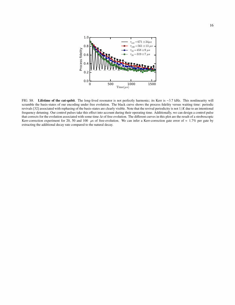
FIG. S8. Lifetime of the cat-qubit. The long-lived resonator is not perfectly harmonic; its Kerr is −3.7 kHz. This nonlinearity willscramble the basis-states of our encoding under free evolution. The black curve shows the process fidelity versus waiting time: periodicrevivals [32] associated with rephasing of the basis-states are clearly visible. Note that the revival periodicity is not 1/K due to an intentionalfrequency detuning. Our control pulses take this effect into account during their operating time. Additionally, we can design a control pulsethat corrects for the evolution associated with some time ∆t of free evolution. The different curves in this plot are the result of a stroboscopicKerr-correction experiment for 20, 50 and 100 µs of free-evolution. We can infer a Kerr-correction gate error of ≈ 1.7% per gate byextracting the additional decay rate compared to the natural decay.