implementing lockout function with iec 61850 ... · pdf filewithout or with limited power...
TRANSCRIPT
7Implementing Lockout Function with IEC 61850 Communications Based P&C Systems
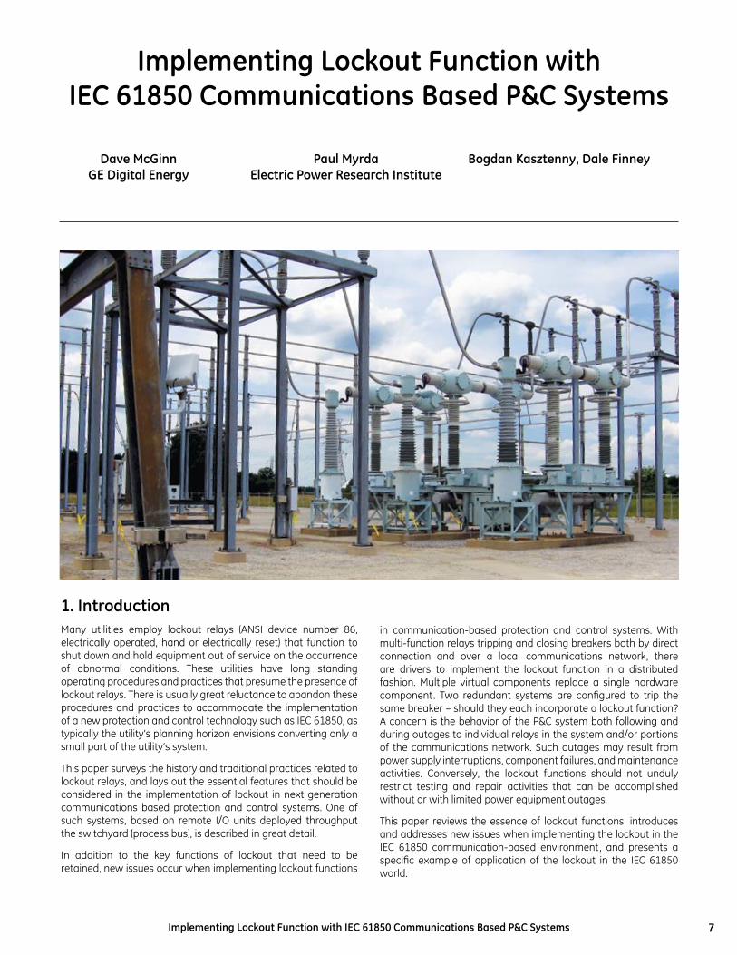
1. IntroductionMany utilities employ lockout relays (ANSI device number 86, electrically operated, hand or electrically reset) that function to shut down and hold equipment out of service on the occurrence of abnormal conditions. These utilities have long standing operating procedures and practices that presume the presence of lockout relays. There is usually great reluctance to abandon these procedures and practices to accommodate the implementation of a new protection and control technology such as IEC 61850, as typically the utility’s planning horizon envisions converting only a small part of the utility’s system.
This paper surveys the history and traditional practices related to lockout relays, and lays out the essential features that should be considered in the implementation of lockout in next generation communications based protection and control systems. One of such systems, based on remote I/O units deployed throughput the switchyard (process bus), is described in great detail.
In addition to the key functions of lockout that need to be retained, new issues occur when implementing lockout functions
Implementing Lockout Function with IEC 61850 Communications Based P&C Systems
Dave McGinnGE Digital Energy
Paul MyrdaElectric Power Research Institute
Bogdan Kasztenny, Dale Finney
in communication-based protection and control systems. With multi-function relays tripping and closing breakers both by direct connection and over a local communications network, there are drivers to implement the lockout function in a distributed fashion. Multiple virtual components replace a single hardware component. Two redundant systems are configured to trip the same breaker – should they each incorporate a lockout function? A concern is the behavior of the P&C system both following and during outages to individual relays in the system and/or portions of the communications network. Such outages may result from power supply interruptions, component failures, and maintenance activities. Conversely, the lockout functions should not unduly restrict testing and repair activities that can be accomplished without or with limited power equipment outages.
This paper reviews the essence of lockout functions, introduces and addresses new issues when implementing the lockout in the IEC 61850 communication-based environment, and presents a specific example of application of the lockout in the IEC 61850 world.
8 Implementing Lockout Function with IEC 61850 Communications Based P&C Systems
2. Traditional LockoutLockout relays are used by many utilities in electrical power transmission substations to trip and hold out of service a protection zone on the occurrence of a relay operation that requires inspection and/or repair before the zone may be safely placed back in service. A protection zone could be a transformer, a bus, a transmission line or feeder, a static capacitor, or other power system element.
A transformer zone lockout relay for instance is tripped by its current differential or gas protection, operations that strongly indicate the presence of transformer damage that would be aggravated by re-energizing the transformer. The current differential and gas protection is therefore connected to operate the lockout relay.
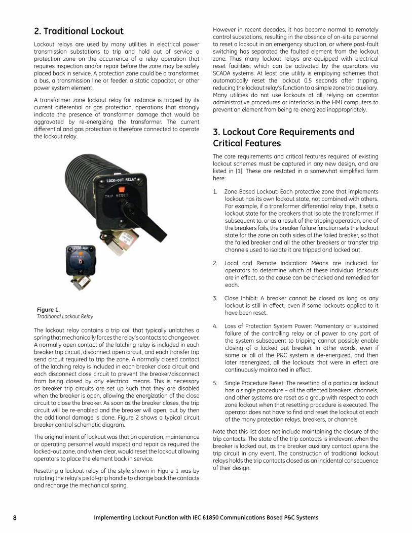
The lockout relay contains a trip coil that typically unlatches a spring that mechanically forces the relay’s contacts to changeover. A normally open contact of the latching relay is included in each breaker trip circuit, disconnect open circuit, and each transfer trip send circuit required to trip the zone. A normally closed contact of the latching relay is included in each breaker close circuit and each disconnect close circuit to prevent the breaker/disconnect from being closed by any electrical means. This is necessary as breaker trip circuits are set up such that they are disabled when the breaker is open, allowing the energization of the close circuit to close the breaker. As soon as the breaker closes, the trip circuit will be re-enabled and the breaker will open, but by then the additional damage is done. Figure 2 shows a typical circuit breaker control schematic diagram.
The original intent of lockout was that on operation, maintenance or operating personnel would inspect and repair as required the locked-out zone, and when clear, would reset the lockout allowing operators to place the element back in service.
Resetting a lockout relay of the style shown in Figure 1 was by rotating the relay’s pistol-grip handle to change back the contacts and recharge the mechanical spring.
However in recent decades, it has become normal to remotely control substations, resulting in the absence of on-site personnel to reset a lockout in an emergency situation, or where post-fault switching has separated the faulted element from the lockout zone. Thus many lockout relays are equipped with electrical reset facilities, which can be activated by the operators via SCADA systems. At least one utility is employing schemes that automatically reset the lockout 0.5 seconds after tripping, reducing the lockout relay’s function to a simple zone trip auxiliary. Many utilities do not use lockouts at all, relying on operator administrative procedures or interlocks in the HMI computers to prevent an element from being re-energized inappropriately.
3. Lockout Core Requirements and Critical FeaturesThe core requirements and critical features required of existing lockout schemes must be captured in any new design, and are listed in [1]. These are restated in a somewhat simplified form here:
1. Zone Based Lockout: Each protective zone that implements lockout has its own lockout state, not combined with others. For example, if a transformer differential relay trips, it sets a lockout state for the breakers that isolate the transformer. If subsequent to, or as a result of the tripping operation, one of the breakers fails, the breaker failure function sets the lockout state for the zone on both sides of the failed breaker, so that the failed breaker and all the other breakers or transfer trip channels used to isolate it are tripped and locked out.
2. Local and Remote Indication: Means are included for operators to determine which of these individual lockouts are in effect, so the cause can be checked and remedied for each.
3. Close Inhibit: A breaker cannot be closed as long as any lockout is still in effect, even if some lockouts applied to it have been reset.
4. Loss of Protection System Power: Momentary or sustained failure of the controlling relay or of power to any part of the system subsequent to tripping cannot possibly enable closing of a locked out breaker. In other words, even if some or all of the P&C system is de-energized, and then later reenergized, all the lockouts that were in effect are continuously maintained in effect.
5. Single Procedure Reset: The resetting of a particular lockout has a single procedure – all the affected breakers, channels, and other systems are reset as a group with respect to each zone lockout when that resetting procedure is executed. The operator does not have to find and reset the lockout at each of the many protection relays, breakers, or channels.
Note that this list does not include maintaining the closure of the trip contacts. The state of the trip contacts is irrelevant when the breaker is locked out, as the breaker auxiliary contact opens the trip circuit in any event. The construction of traditional lockout relays holds the trip contacts closed as an incidental consequence of their design.
Figure 1.Traditional Lockout Relay
9Implementing Lockout Function with IEC 61850 Communications Based P&C Systems
4. Communications Based Protection and Control SystemsDue to pressure to continuously reduce costs, the accelerating pace of aging infrastructure replacement, shrinking workforce, and other factors, utilities are being driven to consider alternatives to the traditional ways of designing, constructing, testing and maintaining protection and control systems, of which lockout is a part. An alternative technology that is rapidly gaining global acceptance is communications based protection and control systems. With this technology, a single communications link, typically an optical fiber, replaces scores of individual copper wires and their associated infrastructure.
A popular protocol for communicating between the various protection and control components is defined in international standard IEC 61850. This standard envisions two distinct communications networks: station bus and process bus. The station bus network uses Ethernet to support communications between relays, station computer (i.e. the local control console), remote control (SCADA) systems, engineering workstations, clocks, data archival systems and so on. The process bus network also uses Ethernet, but to support communications between relays and power apparatus such as current transformers, voltage transformers, circuit breakers, disconnects, power transformers, and so on. The chief challenge of process bus is the
communication of sampled values of the CT and VT waveforms, with sampling at rates of the order of 5kHz, and the precise timing of these samples to the neighborhood of ten microseconds. Latency and throughput are much more critical on process bus than on station bus.
A large number of projects have already been implemented using IEC 61850 station bus, such that this technology can be considered proven. The early adopters are now turning their attention to process bus applications. As process bus implements among other things the communications between relays and breakers, and as the lockout function consists of relays locking out breakers, any universally applicable process bus solution will have to support lockout functionality.
To illustrate how a process bus based protection and control system can readily implement lockout functionality, an example is contained later in this paper. However, to appreciate this example, the reader needs to first understand at a high level how the particular process bus protection and control system used by the example operates.
That system is the HardFiber Process Bus System [2], which is described in the following sections.
Figure 2.CB2 Conventional Control Circuit with Lockout
10 Implementing Lockout Function with IEC 61850 Communications Based P&C Systems
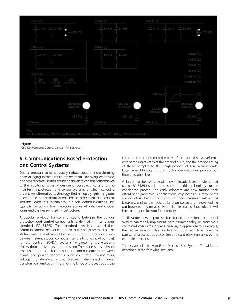
5. The HardFiber Process Bus SystemThe protection and control system presented in this paper is based on an architecture that incorporates application-driven requirements for performance, maintainability, expandability and reliability through the use of remote I/O devices to collect CT/VT signals and process control and status signals [2,3]. In the presented system, these remote I/O devices (Bricks), fulfill the role of IEC 61850 merging units [4].
The IEC 61850-9-2 sampled value output of each Brick is connected via pre-terminated fiber cable to a cross connect panel that directs the appropriate signals to each relay.
In reference to Figure 3, the system includes Bricks mounted at the primary apparatus, relays, pre-terminated cables, and fiber cross connect panels for patching from Bricks to relays.
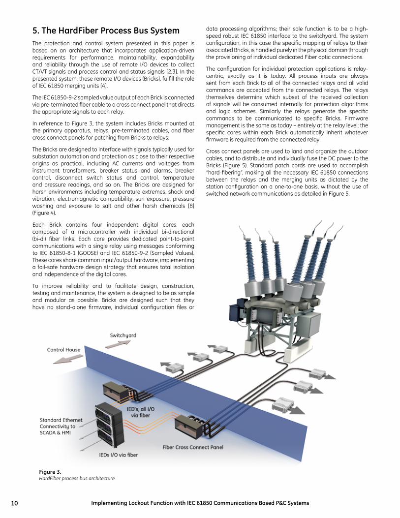
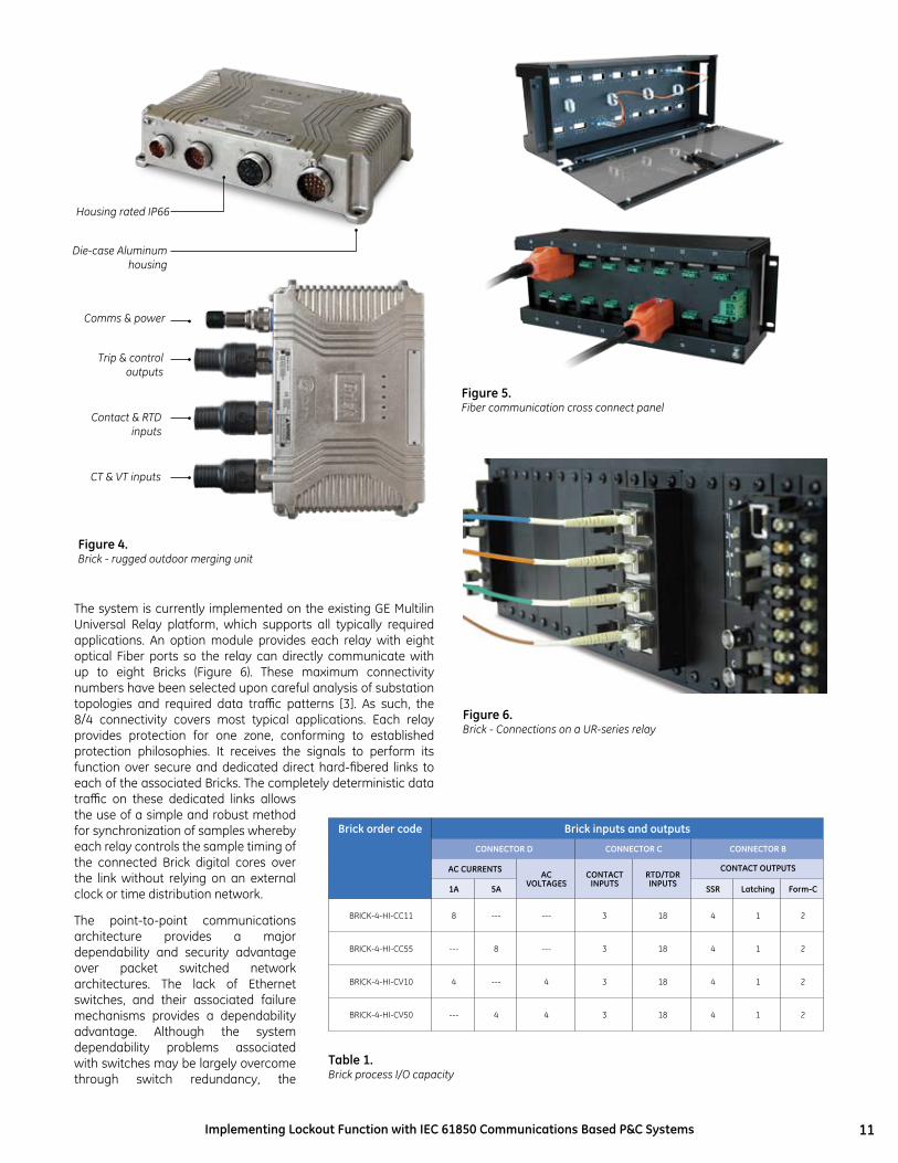
The Bricks are designed to interface with signals typically used for substation automation and protection as close to their respective origins as practical, including AC currents and voltages from instrument transformers, breaker status and alarms, breaker control, disconnect switch status and control, temperature and pressure readings, and so on. The Bricks are designed for harsh environments including temperature extremes, shock and vibration, electromagnetic compatibility, sun exposure, pressure washing and exposure to salt and other harsh chemicals [8] (Figure 4).
Each Brick contains four independent digital cores, each composed of a microcontroller with individual bi-directional (bi-di) fiber links. Each core provides dedicated point-to-point communications with a single relay using messages conforming to IEC 61850-8-1 (GOOSE) and IEC 61850-9-2 (Sampled Values). These cores share common input/output hardware, implementing a fail-safe hardware design strategy that ensures total isolation and independence of the digital cores.
To improve reliability and to facilitate design, construction, testing and maintenance, the system is designed to be as simple and modular as possible. Bricks are designed such that they have no stand-alone firmware, individual configuration files or
data processing algorithms; their sole function is to be a high-speed robust IEC 61850 interface to the switchyard. The system configuration, in this case the specific mapping of relays to their associated Bricks, is handled purely in the physical domain through the provisioning of individual dedicated Fiber optic connections.
The configuration for individual protection applications is relay-centric, exactly as it is today. All process inputs are always sent from each Brick to all of the connected relays and all valid commands are accepted from the connected relays. The relays themselves determine which subset of the received collection of signals will be consumed internally for protection algorithms and logic schemes. Similarly the relays generate the specific commands to be communicated to specific Bricks. Firmware management is the same as today – entirely at the relay level; the specific cores within each Brick automatically inherit whatever firmware is required from the connected relay.
Cross connect panels are used to land and organize the outdoor cables, and to distribute and individually fuse the DC power to the Bricks (Figure 5). Standard patch cords are used to accomplish “hard-fibering”, making all the necessary IEC 61850 connections between the relays and the merging units as dictated by the station configuration on a one-to-one basis, without the use of switched network communications as detailed in Figure 5.
Figure 3.HardFiber process bus architecture
11Implementing Lockout Function with IEC 61850 Communications Based P&C Systems
Figure 4.Brick - rugged outdoor merging unit
Figure 6.Brick - Connections on a UR-series relay
Table 1.Brick process I/O capacity
The system is currently implemented on the existing GE Multilin Universal Relay platform, which supports all typically required applications. An option module provides each relay with eight optical Fiber ports so the relay can directly communicate with up to eight Bricks (Figure 6). These maximum connectivity numbers have been selected upon careful analysis of substation topologies and required data traffic patterns [3]. As such, the 8/4 connectivity covers most typical applications. Each relay provides protection for one zone, conforming to established protection philosophies. It receives the signals to perform its function over secure and dedicated direct hard-fibered links to each of the associated Bricks. The completely deterministic data traffic on these dedicated links allows the use of a simple and robust method for synchronization of samples whereby each relay controls the sample timing of the connected Brick digital cores over the link without relying on an external clock or time distribution network.
The point-to-point communications architecture provides a major dependability and security advantage over packet switched network architectures. The lack of Ethernet switches, and their associated failure mechanisms provides a dependability advantage. Although the system dependability problems associated with switches may be largely overcome through switch redundancy, the
Housing rated IP66
Die-case Aluminumhousing
Comms & power
Trip & controloutputs
Contact & RTDinputs
CT & VT inputs
Figure 5.Fiber communication cross connect panel
Brick order code Brick inputs and outputs
ConnECToR D ConnECToR C ConnECToR B
AC CuRREnTSAC
voLTAGESConTACT
InPuTSRTD/TDR InPuTS
ConTACT ouTPuTS
1A 5A SSR Latching Form-C
BRICK-4-HI-CC11 8 --- --- 3 18 4 1 2
BRICK-4-HI-CC55 --- 8 --- 3 18 4 1 2
BRICK-4-HI-CV10 4 --- 4 3 18 4 1 2
BRICK-4-HI-CV50 --- 4 4 3 18 4 1 2
12 Implementing Lockout Function with IEC 61850 Communications Based P&C Systems
redundancy adds problems in terms of system testing, and increases the number of non-dependability impacting failures that must be attended to. It is important to note that the total number of transceivers is comparable, due to the limited number of Bricks a relay needs to interface to with a practical switchgear topology.
The direct relay to brick communications architecture, without intermediate switches, makes this process bus architecture essentially immune to cyber security threats as there is neither need nor mechanism for external access.
6. ArchitectureThe set points for all anti-islanding protection elements are based on standard settings provided by Hydro One, a fault study performed by Hydro One, and a study performed by GE Multilin for setting the Rate-of-Change-of-Frequency (ROCOF) element. See the table below. All protection elements trip the generator circuit breaker, initiate a fault report, initiate an oscillography record, and an initiate an event report. The protection must detect all islanding conditions to satisfy utility requirements.
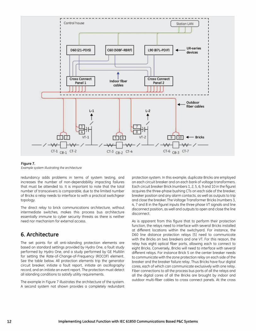
The example in Figure 7 illustrates the architecture of the system. A second system not shown provides a completely redundant
Figure 7.Example system illustrating the architecture
protection system. In this example, duplicate Bricks are employed on each circuit breaker and on each bank of voltage transformers. Each circuit breaker Brick (numbers 1, 2, 5, 6, 9 and 10 in the figure) acquires the three-phase bushing CTs on each side of the breaker, breaker position and any alarm contacts, as well as outputs to trip and close the breaker. The Voltage Transformer Bricks (numbers 3, 4, 7 and 8 in the figure) inputs the three phase VT signals and line disconnect position, as well and outputs to open and close the line disconnect.
As is apparent from this figure that to perform their protection function, the relays need to interface with several Bricks installed at different locations within the switchyard. For instance, the D60 line distance protection relays [5] need to communicate with the Bricks on two breakers and one VT. For this reason, the relay has eight optical fiber ports, allowing each to connect to eight Bricks. Conversely, Bricks will need to interface with several different relays. For instance Brick 5 on the center breaker needs to communicate with the zone protection relay on each side of the breaker and the breaker failure relay. Thus Bricks have four digital cores, each of which can communicate exclusively with one relay. Fiber connections to all the process bus ports of all the relays and all the digital cores of all the Bricks are brought by indoor and outdoor multi-fiber cables to cross connect panels. At the cross

13Implementing Lockout Function with IEC 61850 Communications Based P&C Systems
connect panels, each fiber of each cable is broken out to an LC type optical coupler. Patch cords then interconnect Brick digital cores to relay ports according to the functional requirements and configuration of the station’s power apparatus. Thus continuous and dedicated point-to-point optical paths are created between relays and Bricks, without switches or other active components.
This patching or “hard-fibering” is what gives the HardFiber™ system its name [2]. This hard-fibering approach takes advantage of the fact that a relay needs to talk to only the few Bricks that have input or outputs related to that relay’s function, that only
Figure 8.Hard-fibered cross-connection of Bricks and relays
Figure 9.Brick digital cores sampling synchronously
a few relays are interested in any given Brick, and that the necessary relay-Brick connections change rarely, only when the station one-line changes. For those few instances where additional Brick digital cores are required, for instance for VTs on a large bus, additional Bricks can be installed sharing the same copper interface to the primary apparatus.
Figure 8 provides an expanded view of a portion of the example system. In this example, digital cores from Bricks 1, 3, and 5 are connected to the D60. A single digital core in Brick 5 is connected to the C60 [6], and digital cores from Bricks 5 and 9 are connected to the L90 [7]. Note that the choice of specific cores and specific relay ports is arbitrary – Brick cores and relay ports are functionally identical.
The various relay protection and measuring elements that use AC data from multiple Bricks must have the currents and voltages at various locations sampled at the same instant. The existing method for determining the time of the samples is maintained.
Each relay contains a sampling clock that determines when samples need to be taken. In the case of the UR this clock is phase and frequency locked to the power system quantities measured by that relay, although other sampling schemes are possible. At each tick of the sample clock, a GOOSE Ethernet frame is sent by the relay to each connected Brick digital core. Digital cores sample the quantities on receipt of each frame. As the digital cores are fully independent, different relays may sample at different rates or with different phase, but as each is connected to different and independent cores, there is no conflict. Thus each relay is able to sample in a fashion optimal for its application, independently from other relays, and no external clocks are required.
14 Implementing Lockout Function with IEC 61850 Communications Based P&C Systems
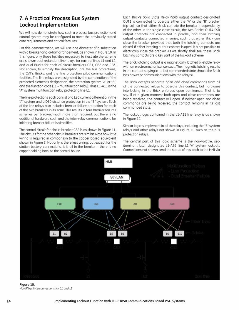
7. A Practical Process Bus System Lockout ImplementationWe will now demonstrate how such a process bus protection and control system may be configured to meet the previously stated core requirements and critical features.
For this demonstration, we will use one diameter of a substation with a breaker-and-a-half arrangement, as shown in Figure 10. In this figure, only those facilities necessary to illustrate the scheme are shown: dual redundant line relays for each of lines L1 and L2, and dual Bricks for each of circuit breakers CB1, CB2 and CB3. Not shown, to simplify the description, are the bus protections, the CVT’s Bricks, and the line protection pilot communications facilities. The line relays are designated by the combination of the protected element’s designation, the protection system “A” or “B”, and the function code (11 – multifunction relay). Thus L1-A11 is the “A” system multifunction relay protecting line L1.
The line protections each consist of a L90 current differential in the “A” system and a D60 distance protection in the “B” system. Each of the line relays also includes breaker failure protection for each of the two breakers in its zone. This results in four breaker failures schemes per breaker, much more than required, but there is no additional hardware cost, and the inter-relay communications for initiating breaker failure is simplified.
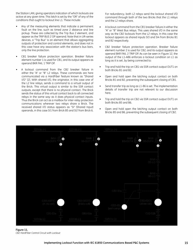
The control circuit for circuit breaker CB2 is as shown in Figure 11. The circuits for the other circuit breakers are similar. Note how little wiring is required in comparison to the copper based equivalent shown in Figure 2. Not only is there less wiring, but except for the station battery connections, it is all in the breaker – there is no copper cabling back to the control house.
Each Brick’s Solid State Relay (SSR) output contact designated OUT1 is connected to operate either the “A” or the “B” breaker trip coil, so that either Brick can trip the breaker independently of the other. In the single close circuit, the two Bricks’ OUT4 SSR output contacts are connected in parallel, and their latching output contacts connected in series, such that either Brick can close the breaker provided that both the latching contacts are closed. If either latching output contact is open, it is not possible to electrically close the breaker. As we shortly shall see, these Brick latching contacts are a key part of the lockout scheme.
The Brick latching output is a magnetically latched bi-stable relay with an electromechanical contact. The magnetic latching results in the contact staying in its last commanded state should the Brick loss power or communications with the relay(s).
The Brick accepts separate open and close commands from all of the connected relays to operate this contact, but hardware interlocking in the Brick enforces open dominance. That is to say, if at a given moment both open and close commands are being received, the contact will open. If neither open nor close commands are being received, the contact remains in its last commanded state.
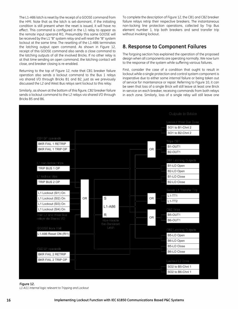
The lockout logic contained in the L1-A11 line relay is as shown in Figure 12.
Similar logic is implement in all the relays, including the “B” system relays and other relays not shown in Figure 10 such as the bus protection relays.
The central part of this logic scheme is the non-volatile, set-dominant latch designated L1-A86 (line L1 “A” system lockout). Connections not shown send the status of this latch to the HMI via
Figure 10.HardFiber Interconnections for L1 and L2
15Implementing Lockout Function with IEC 61850 Communications Based P&C Systems
the Station LAN, giving operators indication of which lockouts are active at any given time. This latch is set by the “OR” of any of the conditions that ought to lockout line L1. These include:
• Any of the measuring elements that indicate a permanent fault on the line, such as timed zone 2 distance and line pickup. These are collected by the Trip Bus 2 element, and appear as the TRIP BUS 2 OP operand. Note that in UR-series devices, a “Trip Bus” is an element that allows aggregating outputs of protection and control elements, and does not in this case have any association with the station’s bus bars, only the line protection.
• CB1 breaker failure protection operation. Breaker failure element number 1 is used for CB1, and its output appears as operand BKR FAIL 1 TRIP OP.
• A lockout command from the CB2 breaker failure in either the “A” or “B” L2 relays. These commands are here communicated via a HardFiber feature known as “Shared I/O” [2]. With shared I/O, the originator, in this case one of the L2 line relays, sends a command to a virtual output of the Brick. This virtual output is similar to the SSR contact outputs, except that there is no physical contact. The Brick sends the status of this virtual contact back to all connected relays in the same way as it does physical contact inputs. Thus the Brick can act as a mailbox for inter-relay protection communications wherever two relays share a Brick. The received shared I/O status appears as “SI” (Shared Input) operands, in this case SI1 from Brick B5 and SI2 from Brick 6.
For redundancy, both L2 relays send the lockout shared I/O command through both of the two Bricks that the L1 relays and the L2 relays share.
• A lockout command from the CB1 breaker failure in either the “A” or “B” West Bus relays. This uses shared I/O in the same way as the CB2 lockouts from the L2 relays. In this case the lockout appears as shared inputs SI3 and SI4 from Bricks B1 and B2 respectively.
• CB2 breaker failure protection operation. Breaker failure element number 2 is used for CB2, and its output appears as operand BKR FAIL 2 TRIP OP. As can be seen in Figure 12, the output of the L1-A86 enforces a lockout condition on L1 as long as it is set, by being connected to:
• Trip and hold the trip on CB1 via SSR contact output OUT1 on both Bricks B1 and B2.
• Open and hold open the latching output contact on both Bricks B1 and B2, preventing the subsequent closing of CB1.
• Send transfer trip as long as L1-86 is set. The implementation details of transfer trip are not relevant to our discussion here.
• Trip and hold the trip on CB2 via SSR contact output OUT1 on both Bricks B5 and B6.
• Open and hold open the latching output contact on both Bricks B5 and B6, preventing the subsequent closing of CB2.
Figure 11.CB2 HardFiber Control Circuit with Lockout
16 Implementing Lockout Function with IEC 61850 Communications Based P&C Systems
The L1-A86 latch is reset by the receipt of a GOOSE command from the HMI. Note that as the latch is set-dominant, if the initiating condition is still present when the reset is issued, it will have no effect. This command is configured in the L1 relay to appear as the remote input operand RI1. Presumably this same GOOSE will be received by the L1 “B” system relay and will reset the “B” system lockout at the same time. The resetting of the L1-A86 terminates the latching output open command. As shown in Figure 12, receipt of this GOOSE command also sends a close command to the latching outputs of all the involved Bricks. If no other relay is at that time sending an open command, the latching contact will close, and breaker closing is re-enabled.
Returning to the top of Figure 12, note that CB1 breaker failure operation also sends a lockout command to the Bus 1 relays via shared I/O through Bricks B1 and B2, just as we previously discussed the L2 and West Bus relays sent lockout to this relay.
Similarly, as shown at the bottom of this figure, CB2 breaker failure sends a lockout command to the L2 relays via shared I/O through Bricks B5 and B6.
To complete the description of Figure 12, the CB1 and CB2 breaker failure relays retrip their respective breakers. The instantaneous non-locking line protection operations, collected by Trip Bus element number 1, trip both breakers and send transfer trip without invoking lockout.
8. Response to Component FailuresThe forgoing section has explained the operation of the proposed design when all components are operating normally. We now turn to the response of the system while suffering various failures.
First, consider the case of a condition that ought to result in lockout while a single protection and control system component is inoperative due to either some internal failure or being taken out of service for maintenance or repair. Referring to Figure 10, it can be seen that loss of a single Brick will still leave at least one Brick in-service on each breaker, receiving commands from both relays in each zone. Similarly, loss of a single relay will still leave one
Figure 12.L1-A11 Internal logic relevant to Tripping and Lockout
17Implementing Lockout Function with IEC 61850 Communications Based P&C Systems
relay in-service for each protection zone. Loss of either a single indoor or a single outdoor cable is equivalent to loosing the corresponding relay or Brick. Referring to Figure 11, it can be seen that either Brick acting alone can trip its breaker and lockout breaker closing. Finally, referring to Figure 12, it can be seen that the system “A” relay does not rely on system “B”, and as system “B” is similar to system “A”, the converse is true, so it can be concluded that either relay acting alone can initiate lockout. Thus it is shown that the design can establish lockout with any single contingency failure. In fact, there are many cases of multiple component failure that do not impact the ability to establish lockout.
Next, consider the case where lockout has been established on an element, and various protection system failures occur. Loss of power to one or even all of the Bricks has no impact on the pre-existing lockout conditions, as the Brick latching outputs are magnetically latched, and retain their position without power. The latching outputs also retain their position when communication with the relays are lost, and on being power up. A Brick design objective, shown effective by extensive factory type testing, was that Brick failure, vibration and shock do not result in the latching output changing state.
Even if this were to happen, it is not creditable that it occur simultaneously in both Bricks. Thus it can be concluded that a locked out breaker cannot be closed as a result of Brick troubles.
Should power to a relay be lost while in the lockout state, it will cease issuing latch open commands to its Bricks, but the alternate relay should continue to do so, and even if it does not, the Bricks latching output will not change state till specifically commanded to do so. When the relay is again powered up, as the lockout latch is non-volatile, it will simply resume sending latch open commands. If the relay is replaced with another, the new relay may not send latch open commands, but neither will it send latch close commands till initiated by the HMI. Thus it can be concluded that a locked out breaker cannot be closed as a result of relay troubles either.
9. ConclusionsThis paper surveyed the history and traditional practices of lockout in electrical power transmission substations. It outlined the high-level design principles for lockout functionality, with the objective of applying them to process bus based protection and control systems.
This paper has presented a new process bus system for protection and control using IEC-61850 process bus as a technical framework. Other papers [3, 8] present the option to duplicate the remote I/O devices in the presented system in order to achieve an unprecedented level of security, dependability and availability.
Special attention has been paid to the fail-safe aspect of the design. By relying more on digital interfaces and subsystems, the
system is made more fail-safe: it either works or it does not, with a greatly reduced probability of a subsystem being in a faulted yet undetected state.
As a result, the presented system can be easily argued as being more reliable compared with other implementations of protection and control systems. Rigorous self-monitoring strategy and ability to support fully duplicated I/O layer make it an excellent candidate for application in ultra-critical protection and control systems.
The implementation of the lockout principles in this process bus based
protection and control system is illustrated using an example from a typical switchyard. An analysis of the system’s response to various failure conditions shows that the objectives of lockout are fully met.
9. References[1] R. Brantley, K. Donahoe, J. Theron, E. Udren, “The Application
of IEC 61850 to Replace Auxiliary Devices Including Lockout Relays” (60th Annual Georgia Tech Protective Relaying Conference May 3-5, 2006, Atlanta, Georgia)
[2] HardFiber Process Bus System Reference Manual, GE Publication GEK-113500.
[3] B. Kasztenny, D. McGinn, S. Hodder, D. Ma, J. Mazereeuw, M. Goraj, “A Practical IEC61850-9-2 Process Bus Architecture Driven by Topology of the Primary Equipment” (42 CIGRE Session, Paris, August 24-29, 2008, paper B5-105).
[4] IEC International Standard “Communication networks and systems in substations - Part 9-2: Specific Communication Service Mapping (SCSM) – Sampled values over ISO/IEC 8802-3”, (IEC Reference number IEC/TR 61850-9-2:2004(E), IEC, Geneva, Switzerland).
[5] D60 Line Distance Protection System Instruction Manual D60, GE Publication GEK-113482
[6] C60 Breaker Protection System UR Series Instruction Manual C60, GE Publication GEK-113479
[7] L90 Line Current Differential System UR Series Instruction Manual L90, GE Publication GEK-113488
[8] B. Kasztenny, D. McGinn, S. Hodder, V. Muthukrishnan, “Microprocessor-based Protection with Enhanced Security and Dependability for Ultra-Critical Applications”, Proceedings of the 2nd Nuclear Relay Conference, San Diego, California, Sep 24-26, 2008.
“By RELyInG MoRE on
DIGITAL InTERFACES AnD
SuBSySTEMS, THE SySTEM
IS MADE MoRE FAIL-SAFE:
IT EITHER woRKS oR IT
DoES noT”
041210-v5