important: keep for future reference - adobetrek.scene7.com/is/content/trekbicycleproducts/asset...
TRANSCRIPT

i
Important: Keep for future referenceEven if you have ridden a bicycle for years, it is important for EVERY person to read Chapter 1 before riding this bicycle! This manual shows how to ride your new bicycle safely. Parents should speak about Chapter 1 to a child or person who might not understand this manual, especially regarding safety issues such as the use of a coaster brake.
This manual also shows you how to do basic maintenance. Some tasks should only be done by your retailer, and this manual identifies them.
About the CDThis manual includes a CD (compact disc), which provides more comprehensive information. Please view the CD to see information that is specific to your bicycle. If you do not have a computer at home, view the CD on a computer at school, work, or the public library. If your CD does not operate, the same information is on our web site. The address for the web site is on the cover of this manual.
Register your bicycleBicycle registration is the only record we have of who owns this bicycle. If it is necessary to give you new instructions, your registration will provide us with your contact information. If you choose to not complete the registration, make sure you go to the web site frequently. Also, registration and proof of purchase are necessary to make a warranty claim.
It is easy to register on the Trek web site. Choose the web site for your country. If you cannot find one for your country, use the web site for the U.S.: • On the CD, click the link “Register.” • Go to the web address on the cover of this manual and click the links.
Keep this manual with the bicycleThis manual is considered a part of the bicycle that you have purchased. If you sell the bicycle, please give this manual to the new owner.
Meaning of safety signs and languageIn this manual, the Safety Alert symbol, a triangle with an exclamation mark, shows a hazardous situation which, if not avoided, could cause injury. The most common cause of injury is falling off the bicycle. Even a fall at slow speed can cause severe injury or death, so avoid any situation with the special markings of a grey box, safety alert symbol, and these signal words:
‘CAUTION’ indicates the possibility of mild or moderate injury. ‘WARNING’ indicates the possibility of serious injury or death.
This manual complies with these standards:• ANSI Z535.6• AS/NZS 1927:1998• BS 6102 : Part 1: 1992• CEN 14764, 14765, 14766, 14781, 14872,
16054• CPSC 16 CFR 1512• ISO 4210 Parts 1-9 and ISO 8098
If you have questionsThere are many models of Trek bicycles with a variety of equipment, so this manual might contain some instructions that do not apply to your bicycle. Some illustrations might be different from your bicycle. For updates to this manual, visit the Trek website.
If you have questions after you read this manual, consult your retailer. If you have a question or problem that your retailer can not answer or repair, tell us:
Attn: Customer Service 801 W. Madison Street Waterloo, Wisconsin 53594 920.478.4678

ii
Trek Bicycle Owner’s Manual
Table of Contents
Chapter 1: Guide to safe on- and off-road operation
Before a first ride ......................................... 1Life span of a bicycle and its parts .............. 2Before each ride: Checklist .......................... 3Rules to ride safely ....................................... 6Riding instructions ....................................... 8Safeguard your bicycle ..............................10Warning about mechanical work .............11Carbon composite .....................................12Use conditions ..........................................13
Chapter 2: Maintenance Maintenance schedule ..............................15
Chapter 3: Inspection and adjustment
A word about torque specifications .........16Handlebar and stem ..................................17Saddle (seat) and seatpost ........................19Derailleurs ..................................................21Internal gear systems.................................23Shift-levers ..................................................23Brake-levers ................................................24Brakes .........................................................25Wheels ........................................................28Training wheels ..........................................35Cables .........................................................35Headset ......................................................35Crankarms and bottom bracket ................35Pedals ..........................................................35Chain ...........................................................36Reflectors ....................................................36Suspension .................................................36Accessories .................................................37Frameset (frame and fork) ........................37
Chapter 4: Lubrication ................ 40
For more instructions ................. 42
Warranty ............................................42
Foreword: Bicycles, accidents, and safetyA bicycle can be fun when used for transportation, recreation, exercise, or competition. But a bicycle can also be dangerous, especially if you try to ride beyond the limits of your bicycle or the limits of your ability. The skill or ability of a bicycle rider can vary greatly, just like the skill of an automobile driver or a skier. Do not ride in a manner that exceeds your ability.
Each bicycle also has limits because of many properties. This is a partial list:• Design and materials of the bicycle• Maintenance of the bicycle• Use of the bicycle: surface, speed, etc.• Surface of the road or trail
A bicycle cannot protect you in an accidentBicycles are not designed to withstand every situation. In a crash or impact, it is not uncommon for the bicycle to have damage and for you to fall. If you fall, your bicycle can not prevent injury. Cars have bumpers, seat belts, air bags, and crumple zones. Bicycles do not, so even a small crash at slow speed can cause injury or death.
If your bicycle is involved in any kind of impact, crash, or accident, have it inspected thoroughly by your retailer before you ride it again.
Think safetyAlways “Think Safety” and avoid dangerous situations, which are usually obvious. However, not all dangerous situations are obvious. Many of those are shown in this manual; read at least Chapter 1 before you ride.
Some of the high-risk stunts and jumps seen in magazines or videos are very dangerous; even skilled athletes get severe injuries when they crash (and they do crash).
1Chapter 1: Guide to Safe On- and Off-Road Operation
Chapter 1: Guide to safe on- and off-road operationThis chapter explains important things you should know before a first ride, including safety information that is important to follow on every ride.
Before a first rideThis information should be read by anyone before their first ride of this bicycle.
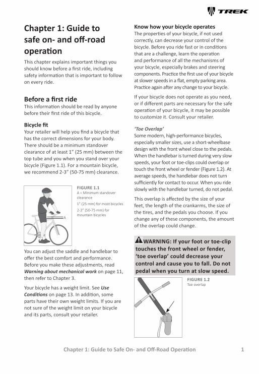
Bicycle fitYour retailer will help you find a bicycle that has the correct dimensions for your body. There should be a minimum standover clearance of at least 1” (25 mm) between the top tube and you when you stand over your bicycle (Figure 1.1). For a mountain bicycle, we recommend 2-3” (50-75 mm) clearance.
You can adjust the saddle and handlebar to offer the best comfort and performance. Before you make these adjustments, read Warning about mechanical work on page 11, then refer to Chapter 3.
Your bicycle has a weight limit. See Use Conditions on page 13. In addition, some parts have their own weight limits. If you are not sure of the weight limit on your bicycle and its parts, consult your retailer.
A
FIGURE 1.1A = Minimum standover clearance
1” (25 mm) for most bicycles
2-3” (50-75 mm) for mountain bicycles
Know how your bicycle operatesThe properties of your bicycle, if not used correctly, can decrease your control of the bicycle. Before you ride fast or in conditions that are a challenge, learn the operation and performance of all the mechanisms of your bicycle, especially brakes and steering components. Practice the first use of your bicycle at slower speeds in a flat, empty parking area. Practice again after any change to your bicycle.
If your bicycle does not operate as you need, or if different parts are necessary for the safe operation of your bicycle, it may be possible to customize it. Consult your retailer.
‘Toe Overlap’Some modern, high-performance bicycles, especially smaller sizes, use a short-wheelbase design with the front wheel close to the pedals. When the handlebar is turned during very slow speeds, your foot or toe-clips could overlap or touch the front wheel or fender (Figure 1.2). At average speeds, the handlebar does not turn sufficiently for contact to occur. When you ride slowly with the handlebar turned, do not pedal.
This overlap is affected by the size of your feet, the length of the crankarms, the size of the tires, and the pedals you choose. If you change any of these components, the amount of the overlap could change.
WARNING: If your foot or toe-clip touches the front wheel or fender, ‘toe overlap’ could decrease your control and cause you to fall. Do not pedal when you turn at slow speed.
FIGURE 1.2Toe overlap

2
Trek Bicycle Owner’s Manual
Chapter 1: Guide to Safe On- and Off-Road Operation
Powerful brakesThe power of bicycle brakes changes with the Use Condition of the bicycle. Many models of modern brakes are very powerful; they are made to stop a bicycle in wet or muddy conditions. If it is necessary for your bicycle to have more—or less—power to stop, consult your retailer about brake adjustments or other brake options for your bicycle. Also read Braking on page 8.
Sharp points, moving parts, hot spots, and pinch pointsSome parts of your bicycle can injure you if mishandled. Sharp points include the teeth of the chainrings and some pedals. Brakes and their parts get hot. Moving parts can cut skin and even break bones. Clamps and pivoting parts such as brake levers can pinch, as can the chain where it runs on to sprocket teeth.
Aero-barAn aero-bar is a forward extension of the handlebar, with arm rests. When riding with your forearms or elbows on an aero-bar, your ability steer and stop the bicycle can be reduced. When more control is needed, change your position so that your hands are near the brake levers and you are not leaning on your elbows or forearms. Also, do not use the arm rests as handles; they are only intended to support your forearms when placed in the center of the pad. Leaning on the edges of the arm rests could break them.
Frame or fork problemFrame problems are not common. As an example of such a problem, some riders could get a “shimmy” or “harmonic oscillation” or “frame wobble” at some speeds.
If you get a shimmy or any other problem, decrease your speed immediately and do not ride the bicycle. If your bicycle behaves in an unusual manner or you hear a noise, immediately stop the bicycle and identify the problem. After any impact, have your retailer inspect the entire bicycle thoroughly. Repair any problem before riding again, or take the bicycle to your retailer for service.
WARNING: A frame or fork problem could decrease your control and cause you to fall. If your bicycle gets a shimmy or any other problem, decrease your speed immediately. Take your bicycle to your retailer for inspection and service.
WARNING: A bicycle is subjected to wear and high stress. Different materials and components may react to wear or stress fatigue in different ways. If the design life of a component has been exceeded, it may suddenly fail, possibly causing injuries to the rider.
Life span of a bicycle and its partsBicycles are not indestructible, and their parts will not last forever. If your use of a bicycle increases the forces on it through hard riding, difficult conditions, or increased mileage, you should replace your bicycle or its parts more frequently than riders who ride less or ride smoothly and carefully.
The safe life of a part is determined by its construction, materials, use, maintenance, rider weight, speed, terrain, and environment (humidity, salinity, temperature, etc.)—so it is not possible to give an accurate timetable for replacement. Any form of crack, scratches, or change of color in high-stress areas indicate that the life of the component has been reached and the part should be replaced. If you are not sure if you should replace a part, consult your retailer.
In some cases, a lighter frame or part has a longer life than a heavier one. However, better maintenance, more frequent inspections, and more frequent replacement are necessary for a light-weight, high-performance bicycle and its parts.

3Chapter 1: Guide to Safe On- and Off-Road Operation
Before each ride: ChecklistThe checklist that follows shows critical areas for you to check. If your bicycle has a carbon fiber composite frame, fork, or parts, also read the special Carbon Composite information on page 12. If a part of your bicycle does not function correctly, use the instructions in this manual to repair your bicycle, or take your bicycle to your retailer for service. Do not ride a bicycle with a part that is damaged; replace the part. This is not a complete maintenance program.
WARNING: A bicycle that does not operate correctly can decrease your control and cause you to fall. Fully check all of your bicycle before each ride, and do not ride your bicycle until you correct any problem.
Check the saddle (seat) and SeatpostMake sure the saddle is correctly attached. Try to turn the saddle and seatpost in the frame, and try to move the front of the saddle up and down. The saddle should not move or be loose.
If you choose to adjust the position of the saddle, also follow the inspection procedures in Chapter 3.
Check the handlebar and stemMake sure the stem is correctly attached. It should be in alignment with the front wheel and correctly attached to the fork and handlebar. To check the attachment, try to turn the handlebar from side to side while you hold the front wheel between your knees
Check the frame and forkClosely examine your frame and fork, especially near junctions of the tubing, and clamping or attachment areas. Look for signs of fatigue stress:• Dents • Cracks• Scratches • Deformation• Discoloration • Unusual noisesIf your frame or fork is made of carbon composite, also see page 12.
Check the wheelsCheck the tire inflation. Inflate the tires to the air pressure recommended on the sidewall of the tire. If a lower recommendation applies to the rim, inflate to the lower value.
FIGURE 1.3Function test for the handlebar and stem
WARNING: Excess air pressure can cause the tire to explode off the rim, causing permanent hearing loss or, if riding, a loss of control. Use a hand pump with a reliable pressure gauge, and do not overinflate.
Make sure the wheels are straight. Turn the wheel and check the rim when it goes through the brake-pads or the frame. The rim should not wobble up and down or from side to side.
WARNING: A handlebar end that is not plugged or covered can cut in a crash. Parents should regularly inspect a child’s bicycle. Replace damaged or missing grips.
(Figure 1.3). To check the connection of the handlebar, try to twist it in the stem. The handlebar should not move or be loose. Make sure that no cables are pulled or caught when you turn the wheel from side to side.
Make sure grips are secure and that the ends of the handlebar are covered or that plugs are correctly inserted into the ends of the handlebar.

4
Trek Bicycle Owner’s Manual
Chapter 1: Guide to Safe On- and Off-Road Operation
WARNING: A brake system that is dirty, worn, damaged, or not adjusted correctly could decrease your control and cause you to fall. Make a full inspection of the brakes before each ride. If your brakes do not operate correctly, do not ride your bicycle. Adjust the brakes or take your bicycle to your retailer for service.
Check the brakesUse the inspection instructions for the type of brake(s) on your bicycle:• Hand-rim brake: a cable connects a hand
lever to the brake. The lever causes the brake-pads to apply pressure to the rim
• Disc brake: a cable or hydraulic hose connects a hand lever to the brake. The lever causes the brake to apply pressure to a disc attached to the wheel hub.
• Internal hub brake: a cable connects a hand lever to a mechanism inside the hub.
• Coaster brake: when you move the pedals to the rear, the brake engages.
FIGURE 1.4Test for loose condition
FIGURE 1.6Brake pad alignment
1. Brake-pad in alignment with rim surface 2. Pad and rim should be parallel, with 1-2 mm clearance
3. Direction that the rim turns
4. 0.5-1.0 mm toe-in
1
2
3
4
WARNING: A wheel attachment device that is not correctly adjusted and closed can allow the wheel to be loose or come off, suddenly stop the wheel, decrease your control, and cause you to fall. Follow the instructions in Chapter 3 to make sure the wheels are correctly attached before you ride your bicycle.
Make sure the wheels are attached correctly. Lift your bicycle and hit the top of the tire with a solid blow (Figure 1.4). The wheel should not come off, be loose, or move from side to side.
Your bicycle may use one or more systems to attach the wheels to the frame (Figure 1.5). For instructions about adjustment and closure of the wheel attachment devices on your bicycle, and additional inspection specific to those devices, see Chapter 3.
If you are not familiar with the attachment devices on your wheels, we also recommend you ask your retailer to demonstrate them for you.
FIGURE 1.5Wheel attachment types:
1. Traditional quick-release
2. Nutted axle
3. Threaded skewer (with hex wrench)
4. OCC thru-axle
5. DT RWS thru-axle
1
2
3
4
5
Make sure the cables and housing are properly secured to the frame or fork so that they cannot interfere or get caught on moving parts.
Hand-rim brake: Pull the lever to make sure the brake moves freely and stops your bicycle. If the lever can be pulled to the handlebar, the brake is too loose. The brake-

5Chapter 1: Guide to Safe On- and Off-Road Operation
CAUTION: An internal hub brake gets very hot during use and could burn skin. Do not touch the hub or cooling fins when hot.
CAUTION: A disc brake and disc get very hot during use and could burn skin. Also, the disc edges can be sharp and could cut skin. Do not touch the disc or disc brake when hot or when the disc turns.
Internal hub brake: Pull the lever to make sure the brake moves freely and stops your bicycle. If more than 15 mm (5/8”) of lever movement is necessary to stop your bicycle, the brake is too loose. If less than 7 mm of lever movement stops your bicycle, the brake is too tight.
Check the lights and reflectorsMake sure all reflectors are clean and in their correct position. Also make sure the reflectors are not covered or obstructed by clothing or anything on your bicycle.
Make sure the lights operate correctly and that batteries are charged. If the lights use a dynamo, make sure the dynamo is mounted correctly and cannot move.
Some countries, localities, or governments have specific requirements for lights, such as colors or types. Check before traveling with your bicycle.
WARNING: A bicycle without correct lights and reflectors might be difficult for other people to see, and you might not be able to see. If you can not see, or other people can not see you, you could have an accident. In low visibility conditions, use a front light, a rear light, and reflectors.
Coaster brake: The brake should engage before the crankarms turn 60 degrees (1/6 turn). The chain operates the brake, so make sure the chain has the correct tension so that it can not fall off. There should be between 1/4 to 1/2” (6-12 mm) total vertical movement of the chain (Figure 1.7).
Check the suspensionAdjust your suspension for your use, and make sure that no suspension component can “bottom-out,” or be fully compressed. Complete suspension adjustment instructions are available on our web site.
FIGURE 1.7Test for chain tension
pads should be in alignment with the rim surface (Figure 1.6). When the brake is not applied, the brake-pads should be 1 to 2 mm from the rim. If the brake-pads are too near the rim, the brake is too tight.
Disc brake: Pull the lever to make sure the brake moves freely and stops your bicycle. If the lever can be pulled to the handlebar, the brake is too loose. When the brake is not applied, the brake-pads should be 0.25-0.75 mm away from the disc. If the pads are too near the disc, the brake is not in alignment or the brake is too tight. With a hydraulic brake system, there should be no leaks of brake fluid.
6
Trek Bicycle Owner’s Manual
Chapter 1: Guide to Safe On- and Off-Road Operation
Rules to ride safelyObey local bicycle lawsMost national, state, or local areas have special laws for bicycle riders. The requirements for items such as lights and reflectors change between areas. To learn what is required where you ride, consult your local bicycle club or the Department of Transportation (or the equivalent). These are some of the more important rules:
• Use correct hand signals.• Ride one at a time (single file) when you
ride with other bicycle riders.• Ride on the correct side of the road; do not
ride in the opposite direction of traffic.• Ride defensively; be prepared for all
situations.
Watch for cars, pedestrians, and other hazardsA bicycle rider can be hard to see, and many people do not know the rights and special considerations of a bicycle rider.
Alert others. If a car suddenly moves into your lane, a pedestrian steps in front of you, or someone opens the door of a parked car, you could be in an accident. Attach a horn or bell to your bicycle and use it to tell other people that you are near.
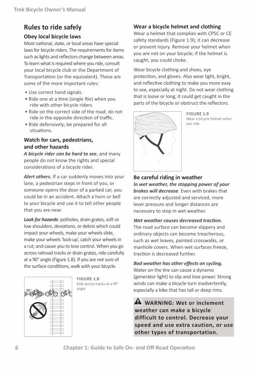
Look for hazards: potholes, drain grates, soft or low shoulders, deviations, or debris which could impact your wheels, make your wheels slide, make your wheels ‘lock-up’, catch your wheels in a rut; and cause you to lose control. When you go across railroad tracks or drain grates, ride carefully at a 90° angle (Figure 1.8). If you are not sure of the surface conditions, walk with your bicycle.
Wear a bicycle helmet and clothingWear a helmet that complies with CPSC or CE safety standards (Figure 1.9); it can decrease or prevent injury. Remove your helmet when you are not on your bicycle; if the helmet is caught, you could choke.
Wear bicycle clothing and shoes, eye protection, and gloves. Also wear light, bright, and reflective clothing to make you more easy to see, especially at night. Do not wear clothing that is loose or long; it could get caught in the parts of the bicycle or obstruct the reflectors.
Be careful riding in weatherIn wet weather, the stopping power of your brakes will decrease. Even with brakes that are correctly adjusted and serviced, more lever pressure and longer distances are necessary to stop in wet weather.
Wet weather causes decreased traction. The road surface can become slippery and ordinary objects can become treacherous, such as wet leaves, painted crosswalks, or manhole covers. When wet surfaces freeze, traction is decreased further.
Bad weather has other effects on cycling. Water on the tire can cause a dynamo (generator light) to slip and lose power. Strong winds can make a bicycle turn inadvertently, especially a bike that has tall or deep rims.
WARNING: Wet or inclement weather can make a bicycle difficult to control. Decrease your speed and use extra caution, or use other types of transportation.
FIGURE 1.8Ride across tracks at a 90° angle
45°
90°
FIGURE 1.9Wear a bicycle helmet when you ride

7Chapter 1: Guide to Safe On- and Off-Road Operation
Be seen (especially at night)Your bicycle has a full set of reflectors. Inspect them before every ride.
However, reflectors do not make you easy to see unless light is pointed at them. Reflectors do not help your vision, but good bicycle lights can. If you ride at dusk, at night, or in low-visibility conditions, consult your retailer to find equipment or materials that help your vision and that meet local requirements.
WARNING: When you ride in low-visibility conditions such as fog, dusk, or night, you might be difficult to see, which could lead to an accident. Use a front light and rear light when you ride in conditions with low light or low visibility.
Think safetyYou can prevent many bicycle accidents if you use common sense and think about safety. Here are some examples:• Check your bicycle before every ride.• Do not ride ‘no hands.’• Do not ride with a loose object or pet (or its
leash) attached to the handlebar or other part of your bicycle.
• Do not ride while intoxicated or while you use medications which can make you drowsy.
• Do not ride distracted. Using a mobile phone, music player, or similar device while riding can distract you and may cause a dangerous situation, or decrease your control and cause you to fall. Observe rules or laws where you ride that prohibit or restrict the use of mobile phones..
• Do not ‘ride double.’ Most bicycles are designed for only one rider.
• Do not ride above your skill level.• Do not ride abusively. Ride in the Use
Conditions specified for your bicycle type. • Ride carefully when off-road. Ride only on
the trails. Do not ride over rocks, branches, or depressions. When you approach a descent, decrease your speed, move your weight low and to the rear, and use the rear brake more than the front.
• Let someone know where you are going and when you plan to return.
• Avoid riding in large groups. Riding close to other riders can make it difficult for you to see road hazards, and you will have very little time to react to those that you do see. When another rider is close, a sudden change in direction or speed can cause you to lose control of your bicycle. Also, large groups of cyclists can cause problems for other users of the roadway.
• Do not ride too fast. Higher speed creates higher risk. Your wheels might slide or a small bump could cause an impact to your frame or fork. Higher speed results in higher forces if a crash occurs. Control your bicycle at all times. For children, the limit of speed is much lower. This is especially true of bicycles equipped with training wheels.
WARNING: Training wheels prevent the regular lean of a bicycle when the rider makes a turn. If the child turns too quickly, the bicycle can fall. With training wheels, do not permit a child to ride fast or turn suddenly.
WARNING: You add to your risk of injury when you use your bicycle in an incorrect manner: • Jump your bicycle • Ride over sticks, debris, or other obstacles • Do bicycle stunts • Ride in severe off-road terrain • Ride fast, in competition, or “downhill” • Ride in an unusual manner These are examples of misuse that add to the stress on each part of your bicycle. High stress can cause the frame or a part to break, and increases your risk of injury. To decrease your risk of injury, use your bicycle correctly.

8
Trek Bicycle Owner’s Manual
Chapter 1: Guide to Safe On- and Off-Road Operation
Riding instructionsThis section explains the basics of riding technique.
BrakingAlways ride with a safe distance between you and other vehicles or objects; use your brakes. Adjust distances and brake forces for the conditions in which you ride.
Coaster brakesParents should explain this to a child. If your bicycle has a “coaster brake” activated by the pedals, you apply the brake by pedalling backwards. To apply the greatest force, the crankarms should be horizontal when you apply the brake. The crank will rotate before the brake starts to work, so start to apply the brake with the rear pedal slightly higher than horizontal (Figure 1.10).
WARNING: Brake force applied to the front-wheel suddenly or too fully could lift the rear wheel off the ground or cause the front wheel to slide out from below you. This could decrease your control and cause you to fall. Apply both brakes at the same time, and move rearward on your bicycle.
ShiftingYou should shift to the gear combination that is most comfortable for the conditions, a gear that lets you to pedal at a constant rate. There are two shifting systems: derailleur (external) and internal.
To shift gears with a derailleurThe left shift-lever controls the front derailleur and the right shift-lever controls the rear derailleur. To prevent dropping or jamming the chain or missing a gear, do not change gears when you ride over bumps. Use only one shift-lever at a time. Change gears only when the pedals and chain move forward. If the chain jams or falls off, it could cause you to lose control and fall.
When you shift gears, decrease the force on the pedals. Lower chain tension helps the chain change gears quickly and smoothly. This can decrease chain and gear wear, and help prevent bent chains, derailleurs, or chainrings.
Do not ride with the chain in the “cross-over” position. If you shift the chain so that it crosses from the biggest sprocket to the biggest sprocket (also, the smallest sprocket to the smallest sprocket), the chain is placed at an extreme angle. This angle causes the chain and gears to run roughly, and will also cause the components to wear at a faster rate.
A movement of the shift-lever from one position to the other position (or movement
FIGURE 1.11Do not over-use the front-wheel brake; the rear wheel can lift and cause you to lose control.
FIGURE 1.10Position to initiate the application of a coaster brake
Hand brakesIn most countries, bicycles are made so that the left brake-lever controls the front-wheel brake. To change this, see Chapter 3.
If your bicycle has two hand brakes, apply both brakes at the same time. Over-use or incorrect use of a front-wheel brake could cause the
rear wheel to lift from the ground which could decrease your control (Figure 1.11).

9Chapter 1: Guide to Safe On- and Off-Road Operation
of the shift-lever to the “shift” position) will promptly move the chain to a different gear.
With Shimano STI road shift-levers and three chainrings, “hold” the front shift lever for a moment before you release it. This is most important when you shift gears from the smallest chainring to the middle chainring.
Some front shift-levers have a ‘tab.’ Slightly move the lever to a lower gear and the derailleur will move in slightly so the derailleur does not touch the chain.
To shift gears with internal gears When you shift gears, coast (do not pedal). Tension on the chain prevents the correct operation of the gear change mechanism and could damage the mechanism.
Pedal systemsIf your feet are connected to the pedals, the connection can allow you to pedal more efficiently, apply greater power to the pedals, and increase your control of the bicycle. Some bicycles are equipped with one of these systems:• Toe-clips and straps attach your feet to the
pedals with a strap and a locator (toe clip), which wraps up and in front of your toes.
• Clipless pedals use a spring-loaded mechanism to engage a cleat, a small plate attached to the bottom of a special cycling shoe.
WARNING: A pedal system that operates incorrectly could cause your feet to become trapped or allow your feet to release from the pedal unexpectedly, causing you to lose control. Before riding, make sure you are familiar with the pedal system and that the pedal system operates correctly.
WARNING: A handlebar end that is not plugged or covered can cut the rider in a crash. Parents should regularly inspect a child’s bicycle and replace damaged or missing grips.
retailer. If you choose to ride with one of these systems, only wear shoes that are compatible with that system. Practice entry and exit from the pedals before you ride. Keep the pedals and your shoes clean and free of debris that could interfere with the pedal system. Make sure any release mechanism operates correctly, and adjust it for your riding.
Carry repair itemsWhen you ride, carry a pump, spare inner tube, patch kit, and tools so you can repair your bicycle if it has a punctured tire or other mechanical problem. If you ride at night, include spare bulbs and batteries for your lights.
Children and safetyIf you allow your child to ride on a bicycle or in a carrier or vehicle attached to a bicycle, you must exert extra vigilance to ensure the child’s safety. Children are not trained to recognize hazards and may not respond correctly in an emergency situation. Never allow a child to ride without supervision. Never leave a child unattended in a child carrier or trailer. Always make sure the child wears protective gear, especially an approved helmet.
It is particularly important that you inspect your child’s bicycle frequently for damage. Pay extra attention to the grips or handlebar covers. In the event of a crash , an exposed handlebar end presents a puncture hazard.
If you attach a child seat or trailer to YOUR bicycle, make sure your bicycle is suitable for the attachment of accessories. Read and follow the instructions that came with the child seat or trailer.If you are not familiar with the pedals or the
correct procedures, read the information that came with the pedal system, or consult your

10
Trek Bicycle Owner’s Manual
Chapter 1: Guide to Safe On- and Off-Road Operation
Safeguard your bicyclePrevent theftPurchase and use a lock that resists bolt cutters and saws. Do not park your bicycle unless it is locked. Also, get a licence for your bicycle from your local police department.
Write the serial number of your bicycle in the front of this manual, and put the manual in a safe location. Then, complete our on-line registration; we will keep the serial number on file.
Parking and storingWhen you complete a ride, put your bicycle in a location where it will not be an obstruction and it has protection from dangerous conditions. Do not park your bicycle near electric motors; ozone from motors can cause damage to rubber and paint. Rain or snow can cause the metal on your bicycle to corrode. Ultraviolet radiation from the sun can fade the paint and crack the rubber or plastic on your bicycle.
Make sure your bicycle can not fall. A fall could cut the handlebar grip or cause damage to the saddle. Incorrect use of a bicycle parking rack could bend your wheels. Do not set your bicycle on its derailleurs. The rear derailleur could bend or dirt could get on the drivetrain.
Before you put away your bicycle for an extended time, clean and service it and apply frame polish. Hang your bicycle off the ground with the tires at approximately half the recommended inflation pressure. Before you ride your bicycle again, be sure it operates correctly.
CleaningIf your frame or a component is dirty, clean it with a soft, moist cloth and bicycle cleaner or a solution of dish soap and water. Do not use industrial solvents or harsh chemicals because they can cause damage to the paint or moving parts.
Every three months, clean and polish the frame finish. Some finishes do not require polish. If you are not certain, consult your retailer.
Avoid heatExcessive heat may damage the adhesive that joins carbon fibers together or the joints of frame parts. Do not exceed 150°F (65°C) exposure to your bicycle. In an extreme case, this temperature may be reached inside a car that is in the sun.
Incidental damage Use care with car racks and work standsClamping devices, such as those found on a work stand or car carrier, can cause damage to the paint or tubes of bicycle frames. To hold the bicycle for repairs, clamp the seatpost. To hold the bicycle for transportation on a motor vehicle, clamp the bicycle by the wheels or fork tips.
When removing a bicycle from a device that clamps the fork tips, lift the bicycle straight out of the clamp. Never tip the bicycle, because the angled forces from the clamp can bend or damage a fork tip. If you accidentally apply a bending force to the fork tip, do not ride the bicycle until your retailer has inspected the fork for damage.
Package your bicycle carefully for shippingWhen you package your bicycle for travel, always use a hard case or carton that will protect your bicycle. Attach pads to all the frame and fork tubes, and use a rigid block to protect the fork tips and maintain structural support of the fork blades. If the bicycle is not packaged correctly, it could be easily damaged in transit. If you are not sure, ask your retailer to package your bicycle for you.
Avoid situations that can damage the finishThe finish, or paint, on your bicycle can be damaged by chemicals (including some sports drinks) or abrasive contact. Dirt can scratch or remove paint (and even frame material), especially where a cable rubs or a strap is placed around a tube. Keep the bicycle clean. Use adhesive padding to prevent rubbing in critical spots.

11
Warning about mechanical workSpecial tools and skills are necessary for the assembly and the first adjustment of your bicycle. Only your retailer should do this.
Incorrect mechanical work can make your bicycle unsafeThe instructions in this manual are written for a person familiar with bicycle mechanics and who has proper tools. Something as simple as an under-tightened bolt can, over time, cause a part to break, leading to a loss of control and an accident.
We recommend you have your bicycle serviced by your retailer. Your safety depends on the correct maintenance of your bicycle, and your retailer has special training and knowledge. If a repair or adjustment is not specifically listed in this manual, for your safety only your retailer should make that repair.
After any repair, or after installing an accessory, check your bicycle as shown in the Before each ride: Checklist in Chapter 1.
Modifications to your bicycle can make it unsafeEach and every part of your new bicycle has been carefully chosen and approved. The safety of accessory or replacement parts, and especially how those parts attach and interface with other parts of the bicycle, is not always apparent. For this reason, you should only replace parts with original equipment or parts that are approved. If you are not sure what parts are approved, ask your retailer. Examples of modifications include this partial list:• Physically altering existing parts (sanding,
filing, drilling, etc.)• Any repairs made to carbon composite
structures• Removing safety equipment such as
reflectors or secondary retention devices• Using adapters for brake systems• Adding a motor or engine• Installing accessories• Changing parts
Only install compatible parts and accessoriesNot all parts and accessories are compatible or safe, so only add a part or accessory that has the approval of Trek. As examples, clamping any accessory on a carbon composite part can weaken or damage the part, and using incorrect brake pads on a carbon rim can cause the rim to overheat and possibly delaminate. As another example, a child carrier puts weight high on the bicycle, which can make your bicycle less stable (some child carriers are compatible with some Trek bicycles). Always check with your retailer before adding an accessory or making any change to your bicycle.
Some parts are safe when used correctly, but can present a hazard if incorrect. For example, any item attached to the handlebar has the possibility of falling into the front wheel, immediately stopping the front wheel and causing a crash. This presents a special hazard if the part has a cable or strap that attaches it to another item on the bicycle.
WARNING: Any modification can make your frame, fork, or part unsafe. A component that is not approved or assembly that is not correct can put high stress on your bicycle or components. A frame, fork, or component with modifications could decrease your control and cause you to fall. Do not sand, drill, file, remove secondary retention devices, install incompatible forks, or make other modifications. Before you add an accessory to your bicycle or change a part of your bicycle, consult your retailer to confirm that it is compatible and safe.
Chapter 1: Guide to Safe On- and Off-Road Operation

Trek Bicycle Owner’s Manual
12 Chapter 1: Guide to Safe On- and Off-Road Operation
suspect internal or hidden damage, please stop riding your bicycle immediately and take it to your retailer for inspection.
Tests for problemsThe following tests can be performed to try to diagnose carbon composite damage. However, these tests are not conclusive: If you are not sure a part is safe, replace it.
Audible test: Listen to your bicycle while you ride, especially for creaking, cracking, popping, or unusual sounds.
Tactile test: As you ride, look for any degradation in shifting or braking performance, or changes in handling or ride quality.
Visual test:1. Clean the part fully with a moist cloth.
Notice if the cloth snags, which could indicate loose carbon composites.
2. Look carefully for possible problems: • Scratches or gouges • Discoloration • Cracks • Loose fibers • Other surface imperfections
Flex test: Do not ride, but use the part in the usual manner while someone carefully checks the part for unusual movement or noise. As an example, to inspect a seatpost, sit on the saddle while someone looks for unusual flex.
Tap test: A movie on the owner’s manual CD (also available on our web site) shows the tap test:1. Clean the part fully with a moist cloth.2. With a coin, tap near the possible damage.3. Listen carefully for variations in sound. Tap
on the part where it is in good condition. Compare the sound. Anything unusual, especially a hollow or dead sound, indicates a possible problem.
Loyalty Replacement programTrek offers a generous Loyalty Replacement program for carbon composite parts that may have been damaged. If you inadvertently damage your carbon composite bicycle or part, or suspect it has damage, visit your authorized Trek retailer to learn more about this program.
FIGURE 1.12Overloaded forks:
• Left: metal fork bent when overloaded
• Right: carbon composite fork withstood much higher load, but completely separated when overloaded
Carbon compositePound for pound, carbon composite (carbon fiber) is stronger than steel or aluminum. This has made it very popular with cyclists.
Reaction to overloadDespite its high strength, carbon composite can still be overloaded (damaged or broken) in an impact, crash, or through mishandling (see page 11).
Carbon composite behaves differently when it is overloaded. An overloaded metal part will bend or deform before it breaks, showing evidence of the load. But when the load exceeds the strength of carbon composite, the carbon composite does not bend; it breaks (Figure 1.12).
A partially overloaded carbon composite part will not bend or deform, so a damaged carbon composite part (with reduced strength due to the damage) may look normal—even after a load that would bend the same part in metal. The carbon composite could appear normal but have internal or hidden damage. If you
WARNING: Carbon composite can conceal damage from an impact or crash. A carbon composite part that has previous damage can break suddenly, causing serious injury or death. If you suspect your bicycle has had an impact or crash, immediately stop the bicycle. Inspect the part before riding, or take the bicycle to your retailer for service.

13Chapter 1: Guide to Safe On- and Off-Road Operation
Use conditions There are many types of bicycles, and each is designed for a specific Use Condition. This section explains those conditions and the weight limit: the sum of rider, gear, and
bicycle. Your bicycle has a frame sticker that indicates its Use Condition. If you are not sure of what type of bicycle you have, consult your retailer.
Condition Terrain Weight limit
Bicycle type or definition
Child Bicycle
Riding for children. A child should not ride without the supervision of a parent. Children should not ride near slopes, curbs, stairs, drop-offs, or pools; or areas that automobiles use.
80 lb (36 kg)
Maximum saddle height of 635 mmUsually a bicycle with 12”, 16”, or 20”
wheels; a child’s tricycle; and includes a trailer bicycle
No quick-release wheel attachment systems
Condition 1
1
Riding on a paved surface where the tires are always on the ground.
175 lb(80 kg)
Road bicycle with 26” wheels
275 lb (125 kg)
Road bicycle with drop-type handlebar
Triathlon, time trial, or speed bicycle
Cruiser with large, 26” tires and swept-back handlebar
300 lb (136 kg)
Adult tricycle
Standard pedelec electric-assist bicycle (RIDE+)
550 lb (250 kg)
Tandem
Condition 2
2
Riding in Condition 1, plus smooth gravel roads and groomed trails with low-angle grades.
Drop-offs of less than 6” (15 cm).
175 lb(80 kg)
Mountain or hybrid bike with 24” wheels
275 lb (125 kg)
Cyclocross bicycle: drop-type handlebar, knobby 700c tires, and cantilever or disc brakes:
300 lb (136 kg)
Shift 4 model: 350 lb (158 kg)
Hybrid or DuoSport bicycle with 700c wheels, tires wider than 28c, and flat handlebar
Urban or City bicycle: hybrid with special equipment such as fenders or a light
Some mountain bicycles
Mountain-bicycle pedelec electric-assist bicycle (Superfly RIDE+)
14
Trek Bicycle Owner’s Manual
Chapter 1: Guide to Safe On- and Off-Road Operation
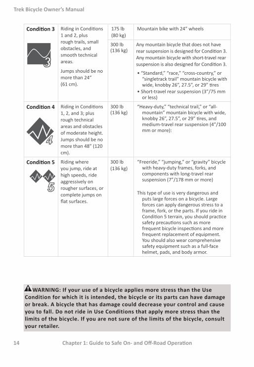
Condition 3
3
Riding in Conditions 1 and 2, plus rough trails, small obstacles, and smooth technical areas.
Jumps should be no more than 24” (61 cm).
175 lb(80 kg)
Mountain bike with 24” wheels
300 lb (136 kg)
Any mountain bicycle that does not have rear suspension is designed for Condition 3. Any mountain bicycle with short-travel rear suspension is also designed for Condition 3.
• “Standard,” “race,” “cross-country,” or “singletrack trail” mountain bicycle with wide, knobby 26”, 27.5”, or 29” tires
• Short-travel rear suspension (3”/75 mm or less)
Condition 4
4
Riding in Conditions 1, 2, and 3; plus rough technical areas and obstacles of moderate height. Jumps should be no more than 48” (120 cm).
300 lb (136 kg)
“Heavy-duty,” “technical trail,” or “all-mountain” mountain bicycle with wide, knobby 26”, 27.5”, or 29” tires, and medium-travel rear suspension (4”/100 mm or more):
Condition 5
5
Riding where you jump, ride at high speeds, ride aggressively on rougher surfaces, or complete jumps on flat surfaces.
300 lb (136 kg)
“Freeride,” “jumping,” or “gravity” bicycle with heavy-duty frames, forks, and components with long-travel rear suspension (7”/178 mm or more)
This type of use is very dangerous and puts large forces on a bicycle. Large forces can apply dangerous stress to a frame, fork, or the parts. If you ride in Condition 5 terrain, you should practice safety precautions such as more frequent bicycle inspections and more frequent replacement of equipment. You should also wear comprehensive safety equipment such as a full-face helmet, pads, and body armor.
WARNING: If your use of a bicycle applies more stress than the Use Condition for which it is intended, the bicycle or its parts can have damage or break. A bicycle that has damage could decrease your control and cause you to fall. Do not ride in Use Conditions that apply more stress than the limits of the bicycle. If you are not sure of the limits of the bicycle, consult your retailer.

15Chapter 2: Maintenance
Chapter 2: MaintenanceThis maintenance schedule is based on normal use. If you ride your bicycle more than average; or in rain, snow, or off-road conditions; do maintenance on your bicycle more frequently than the schedule recommends. If a part malfunctions, check and service it immediately, or consult your retailer. If a part has wear or damage, replace it before you ride your bicycle again.
After initial use, new bicycles should be checked. As an example, cables stretch through use, and this can affect the operation of the shifting or brakes. Approximately two months after you purchase your new bicycle, have your retailer fully check your bicycle.
Even if you did not ride your bicycle much, have your retailer fully service your bicycle each year.
Suggested tools listNot all these tools are necessary for all bicycles.
• Torque wrench with lb•in or Nm gradations• 2, 4, 5, 6, 8 mm hex wrenches• 9, 10, 15 mm open-end wrenches• 15 mm box end wrench• Socket wrench, 14, 15, and 19 mm socket• T25 Torx wrench• No. 1 phillips-head screwdriver• Bicycle inner tube patch-kit, tire-pump with
gauge, and tire levers• Special high-pressure air-pump for a rear
shock or a suspension fork
Maintenance scheduleCheck each ride
Complete the Before each ride: Checklist in Chapter 1 .................................................. 3
Check each weekClean with a moist cloth ............................10
Check each month Accessory bolts ..........................................36 Brakes ....................................................24-27 Cables .........................................................35 Chain ...........................................................36 Apply lubricant ......................................40Derailleurs .............................................21-22 Apply lubricant ......................................41Frame and fork ......................................37-39 Suspension fork bolts ............................36 Apply lubricant ...............................41 Rear suspension bolts ...........................36Headset bearing adjustment ....................35 Internal gear system ..................................23Pedals ..........................................................36Reflectors ....................................................36Rims for wear .............................................28Seatpost bolts .......................................19-20Shift-lever operation ..................................23Spokes .........................................................28Stem bolts .............................................17-18 Training wheels ..........................................35Wheel bearing adjustment .......................28
Check each three months Apply lubricant to brake-levers ................41Apply lubricant to brake arm fixing bolts . 41Bottom bracket ..........................................35Clean and polish finish...............................10Crankarms .................................................35
Each year Apply lubricant to handlebar stem ...........40Apply lubricant to seatpost .......................40Apply lubricant to wheel quick-releases .. 41Replace grease: bottom bracket bearings 40 Replace grease: headset bearings ............41 Replace grease: pedal bearings ................40 Replace grease: pedal threads .................40Replace grease: wheel bearings ...............41Replace grease and oil: suspension forks .. 41

16
Trek Bicycle Owner’s Manual
Chapter 3: Inspection and Adjustment
Chapter 3: Inspection and adjustmentThis chapter gives instructions for inspection and adjustment of the parts of a bicycle. The inspections in this chapter are in addition to those listed in Chapter 1.
Before you perform any work on your bicycle, read the section Warning about mechanical work on page 11.
To inspect some parts, the part will have to be disassembled. This type of inspection should only be done by your retailer.
WARNING: A bicycle that malfunctions could decrease your control and cause you to fall. Fully check all of your bicycle before each ride. If there is a problem, do not ride your bicycle: repair your bicycle or take it to your retailer for service.
A word about torque specificationsTorque is a measure of the tightness of a threaded fastener (screw or bolt). The torque is often written on or near the bolt (on the part). If the part does not have a specification on it, check this manual or the CD, or ask your retailer.
Use a torque wrenchMake sure you do not apply too much or too little torque. Too much can stretch, deform, or break a bolt (or the part it attaches). Too little allows the part to move and leads to fatigue breakage of the bolt (or the part it attaches). A torque wrench (Figure 3.1) provides a precise measurement of the amount of torque.
WARNING: A fastener that is either too loose or too tight can cause damage or break a part. Use a torque wrench to correctly tighten a part, or take the bicycle to your retailer for service.
FIGURE 3.1Torque wrench
Check the function of the part After you use the torque wrench, perform the tests in Chapter 1 and in this chapter. If a part does not have the correct function when it is tightened to the recommended torque, take your bicycle to your retailer for service.
If you are not sure of your work, have your retailer inspect the bicycle after you make any repair.

17
Handlebar and stemThe position of the handlebar is important for control and comfort. You hold the handlebar to steer the bicycle. The handlebar is connected to the fork by the stem. Each month check all the bolts of the stem.
WARNING: Overtightening of stem bolts can cause damage to the steerer of the fork, possibly causing it to break. If the steerer breaks, you could fall.
FIGURE 3.3Quill stem with adjustable rise
1. Handlebar-clamp bolts
2. Expander bolt
3. Angle adjustment bolt (not on all stems)
4. Quill
4
3
2
1
Handlebar plugsMake sure the ends of the handlebar are covered properly. The end covers may prevent the handlebar from cutting the rider in the event of a fall or crash.
Stem typesThere are two types of stems: • Direct-connect (Figure 3.2)• Quill-type (Figure 3.3) Some of the following information applies to just one stem type, and some of it applies to both stem types. Read through this entire section on stems to make sure you have found all the information for your stem.
Chapter 3: Inspection and Adjustment
To adjust the angle of the handlebar (direct-connect or quill stem)1. Loosen the handlebar-clamp bolt(s) on the
stem (Figure 3.2 or Figure 3.3). 2. Move the handlebar. Make sure it is in the
center of the stem. 3. Make sure the top and bottom gaps between
the face plate and stem (Figure 3.2) are even on both sides.
4. Tighten the handlebar-clamp bolt(s) to the specifications on the stem, or for your type of stem, tighten to: • Welded: 100-120 lb•in (11.3-13.6 Nm) • Forged: 150-180 lb•in (17-20.3 Nm)
To adjust the height of the handlebar (direct-connect stem)To adjust the height of the handlebar with a direct-connect stem, the headset bearing must be adjusted. Special tools and training are necessary for bearing adjustment, so only your retailer should do this.
If you choose to move the spacers in the headset assembly, follow the requirements on the next page. Do not add spacers, because the stem will no longer clamp the steerer correctly.
To align a direct-connect stem1. Loosen the steerer-clamp bolts two
to three turns.2. Align the stem with the front wheel. 3. Tighten the steerer-clamp bolts to the
specifications on the stem, or to 100-120 lb•in (11.3-13.6 Nm).
FIGURE 3.2Direct-connect stem
1. Steerer-clamp bolts
2. Handlebar-clamp bolts
3. Face plate
1
2
3

18
Trek Bicycle Owner’s Manual
WARNING: An incorrect headset and stem assembly or missing spacers can cause damage to the steerer of the fork, possibly causing the steerer to break. If the steerer breaks, you could fall.
To align or adjust a quill-type stemTo adjust the height of an adjustable-rise stem, first change the stem angle (see the next section), which gives access to the expander bolt. The expander bolt holds the stem wedge, which secures the stem in the fork.1. Loosen the expander bolt two to three
turns.2. Tap the top of the expander bolt to
loosen the wedge. Use a mallet that has a wood or plastic face.
3. Adjust the handlebar to the necessary height, but the minimum-insertion mark must be in the frame (Figure 3.5).
4. Tighten the expander bolt to the specifications on the stem or to 120 lb•in (13.6 Nm).
WARNING: A quill stem that is too high can cause damage to your bicycle, decrease your control, and cause you to fall. Make sure the minimum-insertion mark (Figure 3.5) is in the frame.
FIGURE 3.5Minimum-insertion mark on quill stem
1. The bicycle frame should hide this line.
A minimum of 2 3/4” (70 mm) of the stem quill should always be in the frame.
1
Minimum spacers with a direct-connect stemOn a bicycle with a direct-connect stem, there must be at least one 5 mm spacer under the stem (in addition to the bearing cover).
On a bicycle with a carbon composite steerer, there must also be at least one 5 mm spacer above the stem (Figure 3.4). If you do not know what type of steerer is on your bicycle, consult your retailer.
To change the angle of an adjustable-rise stem (quill or direct-connect)There are several types of adjustable stems. For illustrations, see the Owner’s Manual CD.1. Loosen the angle adjustment bolt until the
stem angle can be changed.2. Move the stem to the necessary angle.3. Tighten the angle-adjustment bolt to the
specifications on the stem or to 150-170 lb•in (17-20.3 Nm).
FIGURE 3.4Required spacers above and below a direct-connect stem
Chapter 3: Inspection and Adjustment

19Chapter 3: Inspection and Adjustment
WARNING: A saddle that is adjusted incorrectly or does not correctly support your pelvic area can cause injury to your nerves or blood vessels. If your saddle causes pain or numbness, adjust the saddle position. If your saddle still causes pain or numbness, consult your retailer about a change in your position or a saddle that is more comfortable.
Accessories attached to a seatpostSome accessories, such as a trailer cycle, apply a great deal of force to a seatpost. Never attach an accessory to a carbon fiber seatpost. For the compatibility with another seatpost type, consult your retailer.
To adjust the height of the saddleDo not close the seatpost binder with the seatpost out of the frame.1. While someone holds the bicycle, sit on the
saddle without shoes. 2. Loosen the seatpost binder bolt or move
the quick-release lever to the OPEN position.
3. With the crank arms parallel to the seat tube, put your heel on the bottom pedal. Extend the seatpost until your extended leg is straight (Figure 3.7). • When you wear shoes there should be a small bend in your knee with the ball of your foot on the pedal.
4. Make sure the minimum-insertion mark on
WARNING: An incorrectly positioned seatpost or incorrect clamp design can break the saddle rails or the saddle-clamp bolt, and cause you to fall. Only clamp the flat portion of the rails of a correctly fitted saddle in the saddle-clamp.
FIGURE 3.6Seatpost parts
1. Saddle-clamp bolts
2. Seatpost
3. Seatpost binder bolt1
2
3
Saddle (seat) and seatpostThe saddle supports most of your weight on the bicycle. It also controls the extension of your legs and the fore-aft position of your body on the bicycle.
The saddle is connected to the frame by the seatpost and seatpost clamp bolt (Figure 3.6). The seatpost and saddle clamp bolts control the adjustment of the saddle. Each month check the saddle clamp bolt(s) and the seatpost clamp bolt.
Saddle rails have a specific flat area where the seatpost clamps, and the rails vary in materials and diameter. If you choose to replace a saddle or seatpost, make sure the rails fit the seatpost and the saddle is positioned correctly.
With correct adjustment, your bicycle saddle will be comfortable—even for long rides. Adjust the saddle angle to your preference. First, try to ride with the top of the saddle parallel to the ground. For bicycles with rear suspension, move the nose of the saddle down slightly; when your body weight compresses the rear shock, the saddle will be level.
FIGURE 3.7Leg extension with correct saddle height
Saddle rail design and springsIf you attach a child carrier to the rear of the bicycle, exposed saddle springs could injure a child’s fingers. Cover the springs or use a saddle that does not have springs.
20
Trek Bicycle Owner’s Manual
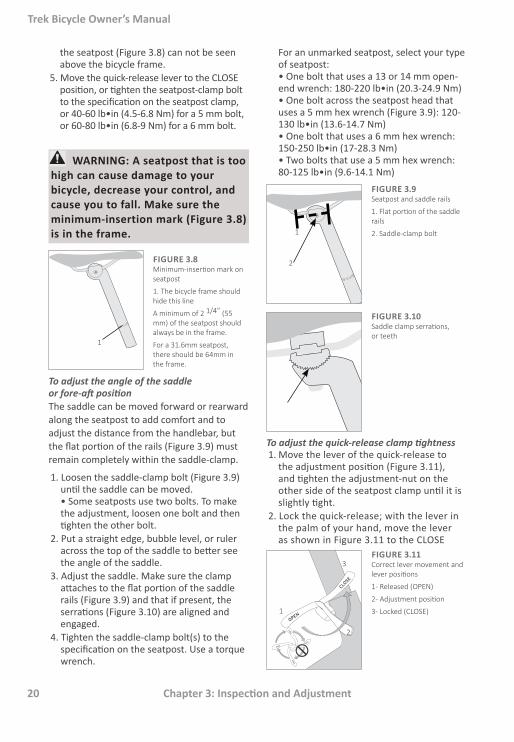
FIGURE 3.8Minimum-insertion mark on seatpost
1. The bicycle frame should hide this line
A minimum of 2 1/4” (55 mm) of the seatpost should always be in the frame.
For a 31.6mm seatpost, there should be 64mm in the frame.
1
FIGURE 3.11Correct lever movement and lever positions
1- Released (OPEN)
2- Adjustment position
3- Locked (CLOSE)
OPEN
OPEN
OPEN
OPEN
1
2
3
To adjust the angle of the saddle or fore-aft positionThe saddle can be moved forward or rearward along the seatpost to add comfort and to adjust the distance from the handlebar, but the flat portion of the rails (Figure 3.9) must remain completely within the saddle-clamp.
1. Loosen the saddle-clamp bolt (Figure 3.9) until the saddle can be moved. • Some seatposts use two bolts. To make the adjustment, loosen one bolt and then tighten the other bolt.
2. Put a straight edge, bubble level, or ruler across the top of the saddle to better see the angle of the saddle.
3. Adjust the saddle. Make sure the clamp attaches to the flat portion of the saddle rails (Figure 3.9) and that if present, the serrations (Figure 3.10) are aligned and engaged.
4. Tighten the saddle-clamp bolt(s) to the specification on the seatpost. Use a torque wrench.
Chapter 3: Inspection and Adjustment
FIGURE 3.9Seatpost and saddle rails
1. Flat portion of the saddle rails
2. Saddle-clamp bolt1
2
the seatpost (Figure 3.8) can not be seen above the bicycle frame.
5. Move the quick-release lever to the CLOSE position, or tighten the seatpost-clamp bolt to the specification on the seatpost clamp, or 40-60 lb•in (4.5-6.8 Nm) for a 5 mm bolt, or 60-80 lb•in (6.8-9 Nm) for a 6 mm bolt.
WARNING: A seatpost that is too high can cause damage to your bicycle, decrease your control, and cause you to fall. Make sure the minimum-insertion mark (Figure 3.8) is in the frame.
For an unmarked seatpost, select your type of seatpost: • One bolt that uses a 13 or 14 mm open-end wrench: 180-220 lb•in (20.3-24.9 Nm) • One bolt across the seatpost head that uses a 5 mm hex wrench (Figure 3.9): 120-130 lb•in (13.6-14.7 Nm) • One bolt that uses a 6 mm hex wrench: 150-250 lb•in (17-28.3 Nm) • Two bolts that use a 5 mm hex wrench: 80-125 lb•in (9.6-14.1 Nm)
FIGURE 3.10Saddle clamp serrations, or teeth
To adjust the quick-release clamp tightness1. Move the lever of the quick-release to
the adjustment position (Figure 3.11), and tighten the adjustment-nut on the other side of the seatpost clamp until it is slightly tight.
2. Lock the quick-release; with the lever in the palm of your hand, move the lever as shown in Figure 3.11 to the CLOSE

21Chapter 3: Inspection and Adjustment
of the derailleur is approximately 0.5 mm from the chain.
4. If there is a barrel-adjuster on the shift-lever or the down tube of the frame, turn the barrel-adjuster fully clockwise.
5. Pull on the cable end, and move the left shift-lever to the small-chainring position.
6. Put the cable in the groove found near the cable-clamp bolt. Pull the cable tight and tighten the clamp bolt to 44-60 lb•in (5.0-6.8 Nm).
To adjust the large-chainring position1. Move the rear derailleur to the smallest
rear cog.2. Turn the high-gear limit-screw (identified
with an “H”) counterclockwise until it can not stop the movement of the derailleur.
3. Turn the crankarms with your hand. Use the shift-lever to carefully move the chain to the outside chainring.
4. Move the outer chain-guide so that it is approximately 0.5 mm from the chain.
5. Tighten the high-gear limit-screw until it resists. If you have turned the screw too far, the front derailleur will rub on the chain or move the chain to a smaller chainring.
To adjust the middle-gear position (with three chainrings)1. Move the chain to the largest front
chainring and the smallest rear cog. 2. Turn the cable barrel-adjuster (on the
down tube, the cable housing, or on the lever) to change the cable tension and align the inner cage of the derailleur until it touches the chain.
position. When you move the lever to the adjustment position, you should feel some resistance. • Do not hold the nut and only turn the lever like a wing-nut (Figure 3.28). Even if you turn the ‘wing-nut’ as tight as you can, this will not make sufficient force to hold the seatpost.
3. If you can close the lever with little or no resistance, the clamp-force is not sufficient. Go back to Step 1 and tighten the adjustment-nut.
4. Align the lever so that it does not touch any part of the bicycle or an accessory part.
5. Test the security of the seatpost as explained in the Before Every Ride Checklist. If the seatpost clamp fails the test, repeat these instructions, or take your bicycle to your retailer for service.
FIGURE 3.12Front derailleur
1. Cable
2. Limit-screws
3. Cable-clamp bolt
1 2
3
DerailleursA derailleur shifts gears by pushing the chain from one cog or chainring to the next. These instructions are written for standard, cable-operated derailleurs. For electronic systems, visit the manufacturer’s website.
Front derailleurWith bicycles that have more than one chainring, the front derailleur moves the chain to change gears.
Each month, or after any adjustment, check the front derailleur. Change gears to all the gear combinations and check these items:• The chain should not come off .• The chain should line up smoothly with
each chainring and not rub the chain.•The derailleur cage should not rub
the crankarm.
To adjust the small-chainring position1. Move the chain to the smallest front
chainring and the largest rear cog. 2. Loosen the cable-clamp bolt (Figure 3.12)
until the cable is free. 3. Turn the low-gear limit-screw (identified
with an “L”) until the inner chain-guide

22
Trek Bicycle Owner’s Manual
Chapter 3: Inspection and Adjustment
Rear derailleurOn bicycles with more than one cog on the rear wheel, the rear derailleur moves the chain to change gears.
Each month, or after any adjustment, check the rear derailleur. Change gears to all the gear combinations to make sure the chain smoothly lines up with each of the rear cogs. Make sure the chain does not come off when you change gears.
To adjust the small-cog position1. Move the chain to the smallest rear cog
and the largest front chainring.2. Loosen the cable-clamp bolt (Figure 3.13)
until the cable is free. 3. Move behind the bicycle to see that the
smallest rear cog, the chain, and both derailleur pulleys are in alignment.
4. If they are not in alignment, turn the high-gear limit-screw (usually identified with an “H”) until they are in alignment.
5. While you pull on the cable, move the shift-lever to the small-cog position.
6. On the shift-lever or down tube, turn the barrel-adjuster fully clockwise. On the rear derailleur, turn the barrel-adjuster fully clockwise, then turn it one turn counterclockwise.
7. Put the cable into the clamp-bolt groove on the rear derailleur, pull the derailleur cable tight, and tighten the cable-clamp bolt to 44-60 lb•in (5.0-6.8 Nm).
To adjust the large-cog position1. Turn the low-gear limit-screw on the rear
derailleur (usually identified with an “L”) counterclockwise until the derailleur can move freely.
2. Carefully move the chain to the smallest front chainring and the largest rear cog. Do not move the rear derailleur too far. The chain can be caught between the large cog and the spokes.
3. Move the rear derailleur pulleys in alignment with the largest cog.
4. Turn the low-gear limit-screw clockwise until it does not turn easily. If you have turned the screw too far, the derailleur will move to the outside of the bicycle.
To align the index system1. Move the chain to the largest front
chainring and the smallest rear cog. 2. Move the rear shift-lever for one click. 3. Make sure the chain moves smoothly
to the second-smallest gear. If the chain makes too much noise or does not change gears, slightly turn the barrel-adjuster. Change the gear again and make sure the change is smooth. If the chain moves to the third smallest gear, turn clockwise the barrel-adjuster until the derailleur pulleys align with the second-smallest gear.
Note: If the derailleur can not be adjusted correctly, the derailleur hanger could be out of alignment. Take your bicycle to your retailer for service because only your retailer should adjust the hanger alignment.
FIGURE 3.13Rear derailleur
1. Limit-screws
2. Barrel-adjuster
3. Cable-clamp bolt
4. Cable1
42
3

23Chapter 3: Inspection and Adjustment
Internal gear systemsThese systems change gears with a mechanism that is in the rear hub. Each month, check the internal gear system.
To adjust a 3 speed system1. Turn the shift-lever to the second-gear
position.2. Check the alignment. The line on the push
rod should align with the indicator on the bell crank window (Figure 3.14). To change the alignment, turn the barrel-adjuster.
3. Move the shift-lever to first gear. Then move the lever to second. Check the adjustment.
To adjust a Nexus 4, 7, or 8 speed system1. Turn the shift-lever to the fourth-gear
position.2. Check the indicator on the rear-hub pulley
(Figure 3.15) with the cog joint bracket. If the red lines are not in alignment, turn the barrel-adjuster until they are in alignment.
3. Move the shift-lever to first gear. Then move the lever to fourth gear. Check the adjustment.
FIGURE 3.14Three-speed rear hub
1. Bell crank window
FIGURE 3.15Nexus rear hub
1. Pulley
2. Cog joint bracket
3. Cable-clamp bolt
3
21
Shift-leversA shift-lever controls a derailleur or internal hub shift mechanism.
Each month, check that the shift levers are firmly attached to the handlebar. Check the operation of a shift lever by inspecting the derailleur or internal shift mechanism.
The position of a shift-lever can be adjusted on the handlebar. There are many types of shift-levers; if a shift-lever on your bicycle is not covered here, see the Owner’s Manual CD or consult your retailer. Each month check that the shifters are secure on the handlebar.
To adjust the position of a lever1. Find the lever-clamp bolt (Figure 3.16
or Figure 3.17).2. Loosen the clamp bolt two to three turns.3. Move the lever.4. Tighten the clamp bolt to
53-69 lb•in (6.0-7.8 Nm).
FIGURE 3.17Lever-clamp bolt, road lever
1. Lever-clamp bolt
FIGURE 3.16Lever-clamp bolt, mountain lever
1. Lever-clamp bolt
2. Barrel-adjuster
1
2
24
Trek Bicycle Owner’s Manual
Chapter 3: Inspection and Adjustment
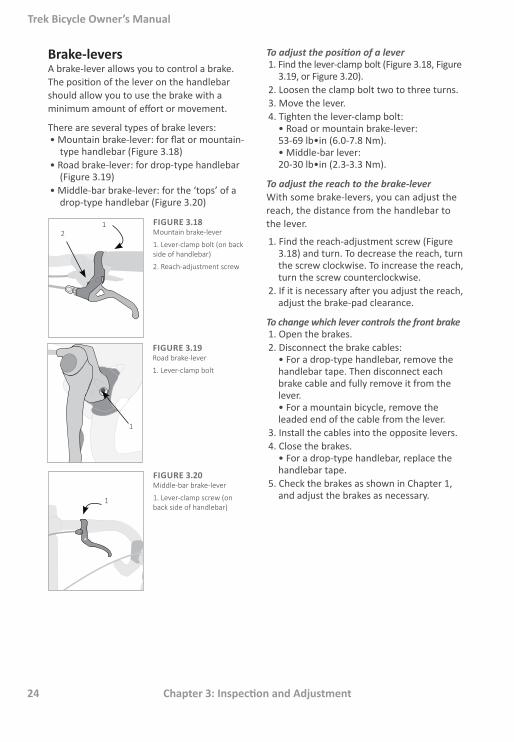
Brake-leversA brake-lever allows you to control a brake. The position of the lever on the handlebar should allow you to use the brake with a minimum amount of effort or movement.
There are several types of brake levers:• Mountain brake-lever: for flat or mountain-
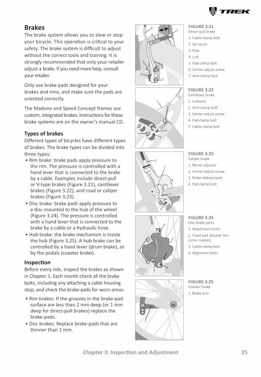
type handlebar (Figure 3.18)• Road brake-lever: for drop-type handlebar
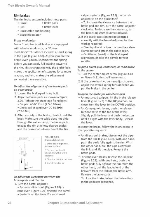
(Figure 3.19)• Middle-bar brake-lever: for the ‘tops’ of a
drop-type handlebar (Figure 3.20)
To adjust the position of a lever1. Find the lever-clamp bolt (Figure 3.18, Figure
3.19, or Figure 3.20).2. Loosen the clamp bolt two to three turns.3. Move the lever.4. Tighten the lever-clamp bolt:
• Road or mountain brake-lever: 53-69 lb•in (6.0-7.8 Nm). • Middle-bar lever: 20-30 lb•in (2.3-3.3 Nm).
To adjust the reach to the brake-leverWith some brake-levers, you can adjust the reach, the distance from the handlebar to the lever.
1. Find the reach-adjustment screw (Figure 3.18) and turn. To decrease the reach, turn the screw clockwise. To increase the reach, turn the screw counterclockwise.
2. If it is necessary after you adjust the reach, adjust the brake-pad clearance.
To change which lever controls the front brake1. Open the brakes.2. Disconnect the brake cables:
• For a drop-type handlebar, remove the handlebar tape. Then disconnect each brake cable and fully remove it from the lever. • For a mountain bicycle, remove the leaded end of the cable from the lever.
3. Install the cables into the opposite levers.4. Close the brakes.
• For a drop-type handlebar, replace the handlebar tape.
5. Check the brakes as shown in Chapter 1, and adjust the brakes as necessary.
FIGURE 3.20Middle-bar brake-lever
1. Lever-clamp screw (on back side of handlebar)
FIGURE 3.19Road brake-lever
1. Lever-clamp bolt
FIGURE 3.18Mountain brake-lever
1. Lever-clamp bolt (on back side of handlebar)
2. Reach-adjustment screw
12
1
1
25Chapter 3: Inspection and Adjustment
FIGURE 3.25Coaster brake
1. Brake arm
1
FIGURE 3.21Direct-pull brake
1. Cable-clamp bolt
2. No touch
3. Pipe
4. Link
5. Pad-clamp bolt
6. Center-adjust screw
7. Arm-clamp bolt
123
4
5
67
FIGURE 3.22Cantilever brake
1. Linkwire
2. Arm-clamp bolt
3. Center-adjust screw
4. Pad-clamp bolt
5. Cable-clamp bolt
1
23
5
FIGURE 3.23Caliper brake
1. Barrel-adjuster
2. Center-adjust screw
3. Brake release lever
4. Pad-clamp bolt
1
2
3
4
FIGURE 3.25Disc brake parts
1. Attachment bolts
2. Fixed-pad adjuster (on some models)
3. Cable-clamp bolt
4. Alignment bolts
3
1
2
BrakesThe brake system allows you to slow or stop your bicycle. This operation is critical to your safety. The brake system is difficult to adjust without the correct tools and training. It is strongly recommended that only your retailer adjust a brake. If you need more help, consult your retailer.
Only use brake pads designed for your brakes and rims, and make sure the pads are oriented correctly.
The Madone and Speed Concept frames use custom, integrated brakes. Instructions for these brake systems are on the owner’s manual CD.
Types of brakesDifferent types of bicycles have different types of brakes. The brake types can be divided into three types: • Rim brake: brake pads apply pressure to
the rim. The pressure is controlled with a hand lever that is connected to the brake by a cable. Examples include direct-pull or V-type brakes (Figure 3.21), cantilever brakes (Figure 3.22), and road or caliper brakes (Figure 3.23).
• Disc brake: brake pads apply pressure to a disc mounted to the hub of the wheel (Figure 3.24). The pressure is controlled with a hand lever that is connected to the brake by a cable or a hydraulic hose.
• Hub brake: the brake mechanism is inside the hub (Figure 3.25). A hub brake can be controlled by a hand lever (drum brake), or by the pedals (coaster brake).
InspectionBefore every ride, inspect the brakes as shown in Chapter 1. Each month check all the brake bolts, including any attaching a cable housing stop, and check the brake-pads for worn areas:
• Rim brakes: If the grooves in the brake-pad surface are less than 2 mm deep (or 1 mm deep for direct-pull brakes) replace the brake-pads.
• Disc brakes: Replace brake-pads that are thinner than 1 mm.
4
4
4
26
Trek Bicycle Owner’s Manual
Chapter 3: Inspection and Adjustment
caliper systems (Figure 3.22) the barrel-adjuster is on the brake itself. • To increase the clearance between the brake-pad and rim, turn the barrel-adjuster clockwise. To decrease the clearance, turn the barrel-adjuster counterclockwise.
2. If the brake-pads can not be adjusted correctly with the barrel-adjuster, further work is required: • Direct-pull and caliper: Loosen the cable-clamp bolt and attach the cable again. • Cantilever: Re-adjust the brake-pad alignment, or take the bicycle to your retailer.
To put a direct-pull, cantilever, or road brake in the center1. Turn the center-adjust screw (Figure 3.18
or Figure 3.21) in small increments.2. If the brake has two center-adjust screws,
adjust the overall spring tension while you put the brake in the center.
To open the brake for wheel removal• For most road calipers, lift the brake release
lever (Figure 3.22) to the UP position. To close, turn the lever to the DOWN position.
• For Campagnolo levers, push the release button that is at the top of the lever. Slightly pull the lever and push the button until it aligns with the lever body. Release the lever.
To close the brake, follow the instructions in the opposite sequence.
• For direct-pull brakes, disconnect the pipe from the link (Figure 3.18). With one hand, push the pads fully against the rim. With the other hand, pull the pipe away from the link, and lift the pipe. Release the brake-pads.
• For cantilever brakes, release the linkwire (Figure 3.21). With one hand, push the brake-pads fully against the rim. With the other hand, pull the leaded end of the linkwire from the fork on the brake-arm. Release the brake-pads.
To close the brake, follow the instructions in the opposite sequence.
Rim brakesThe rim brake system includes these parts: • Brake • Brake pads • Rim • Brake lever • Brake cable and housing • Brake modulator
Brake modulatorSome front direct-pull brakes are equipped with a brake modulator, or “Power modulator.” This device includes a small spring in the pipe (Figure 3.18). As you squeeze the brake lever, you must compress the spring before you can apply full braking power to the rim. This changes the way the brake feels, makes the application of stopping force more gradual, and also makes the adjustment somewhat more sensitive.
To adjust the alignment of the brake-pads on a rim brake1. Loosen the brake-pad fixing bolt.2. Align the brake-pads as shown in Figure
3.26. Tighten the brake-pad fixing bolts: • Caliper: 40-60 lb•in (4.5-6.8 Nm) • Direct-pull or cantilever: 70-80 lb•in (7.9-9 Nm)
3. After you adjust the brake, check it. Pull the lever. Make sure the cable does not slide through the cable clamp, the brake-pads engage the rim at ninety-degree angles, and the brake-pads do not touch the tire.
To adjust the clearance between the brake-pads and the rim1. Turn the barrel-adjuster.
• For most direct-pull (Figure 3.18) or cantilever (Figure 3.21) systems the barrel-adjuster is on the lever. For most road
FIGURE 3.26Brake pad alignment
1. Brake-pad in alignment with rim surface
2. Pad and rim should be parallel, with 1-2 mm clearance
3. Direction that the rim turns
4. 0.5-1.0 mm toe-in
1
2
3
4

27Chapter 3: Inspection and Adjustment
Hub brakesA hub brake such as a coaster brake, drum brake, or internal brake usually requires multiple frame attachments and multiple adjustments. Due to this complexity and the importance to your safety of having the brake adjusted correctly, we highly recommend that any adjustment of a hub brake, or removal of the wheel from the frame, only be done by your retailer.
To remove the rear wheel with internal or drum brakes1. Disconnect the brake cable. Push the cable-
carrier arm forward, and the cable-clamp bolt rearward, so the bolt aligns with the larger diameter hole in the carrier.
2. Pull the cable-clamp bolt out to remove it from the carrier. Slide the brake-cable stop forward to remove it from the brake-arm.
3. Loosen the brake-strap bolt.4. Shift the shift-lever to first gear. 5. Pull the cable-housing out of the gear-cable
housing-stop. 6. Turn the gear-cable clamp bolt until the
washer flats align with the slit in the cog joint bracket.
7. Remove the cable.
Disc brakesWhen the wheel is out of the frame, do not operate the brake lever. With some brakes, the pads automatically adjust their clearance such that you will not be able to insert the disc.
To align a hydraulic disc brake1. Loosen the brake-attachment bolts (Figure
3.22). 2. Fully pull the lever, and tighten the bolts to
100-110 lb•in (11.3-12.4 Nm).
To align a cable-actuated disc brakeThere are three parts to this procedure:A. To adjust the clearance between the right
brake-pad and the disc 1. Turn the fixed-pad adjuster (Figure 3.23). 2. If the pads can not be adjusted correctly in this manner, follow the instructions “To adjust the clearance between the left brake-pad and the disc,” and then adjust the right pad.
B. To adjust the clearance between the left brake-pad and the disc 1. Turn the cable barrel-adjuster: clockwise to increase clearance, counterclockwise to decrease clearance. 2. If the pads can not be adjusted correctly, loosen the cable-clamp bolt and re-attach the cable. Tighten the cable-clamp bolt to 50-70 lb•in (5.7-7.9 Nm). 3. After adjustment, turn the lock-nut clockwise to make sure the adjustment does not change.
C. To align the brake with the disc 1. Loosen the brake-attachment bolts. 2. Slide a business card or other thin object between the right brake-pad and the disc. 3. Pull the lever fully, and tighten the bolts to 100-110 lb•in (11.3-12.4 Nm).
To remove disc brake-pads1. Remove the wheel.2. With your fingers or pliers, hold the
installation tang of the brake-pad and pull out the pad.

28
Trek Bicycle Owner’s Manual
Chapter 3: Inspection and Adjustment
WheelsThe wheels hold you up when riding and allow you to roll along smoothly. Their attachment and integrity are important for your safety.
InspectionBefore every ride, check the wheel attachment as shown in Chapter 1 and in the instructions on the following pages for the types of wheel attachment device(s) on your bicycle.
Also before every ride, check the tire inflation and make sure rims are clean so that the brakes function correctly.
Each month, check the tires for damage or a worn area. As a tire wears thin, it may become more susceptible to puncture. If a cut goes all the way through the casing, or any casing thread show through the tread, replace the tire.
Each month, check that there are no loose spokes or spokes with damage so that the wheel remains straight and strong. Make sure the wheel (hub) bearings are correctly adjusted.
Each month inspect the rims for wear. If the wear-indicators on the brake surface show the rim is worn, or if the brake surface is not flat, replace the rim:
• Aluminum rims: A shallow groove is found around the rim (Figure 3.27). If the outer rim surface is worn such that the groove is no longer visible in any spot, replace the rim.
• Carbon composite rims: A woven material covers the interior uni-directional fibers. If the uni-directional fibers are exposed, replace the rim.
WARNING: Brake-pads remove rim material when you apply the brake. If the brakes remove too much material over time, the rim can become weak and break, decrease your control, and cause you to fall. Regularly check your rims. Replace a rim that is worn.
FIGURE 3.27Rim wear indicator: shallow groove in brake track on aluminum rim
Whenever you change a tire or tube, inspect the rim, tire, and rim strip. This inspection is intended to remove the cause of a puncture or flat tire. Make sure the rim strip is in the correct location and it fully covers all spoke holes or nipples. Check the rim for sharp spots or dents; a rim can be damaged if ridden with a low or flat tire, even for just a few feet. Check the tire casing, and remove any debris.
To check the adjustment of the hub bearings1. Lift the end of the bicycle off the ground
with one hand and try to move the rim from the left to the right. Look, feel, and listen for a movement in the bearings.
2. Turn the wheel and listen for a grinding noise or other noises that are not usual.
3. Repeat these procedures for the other wheel.
If the hub feels loose or makes a grinding noise, service is necessary. The adjustment of the wheel bearings requires special tools and training. Only your retailer should adjust bearings.
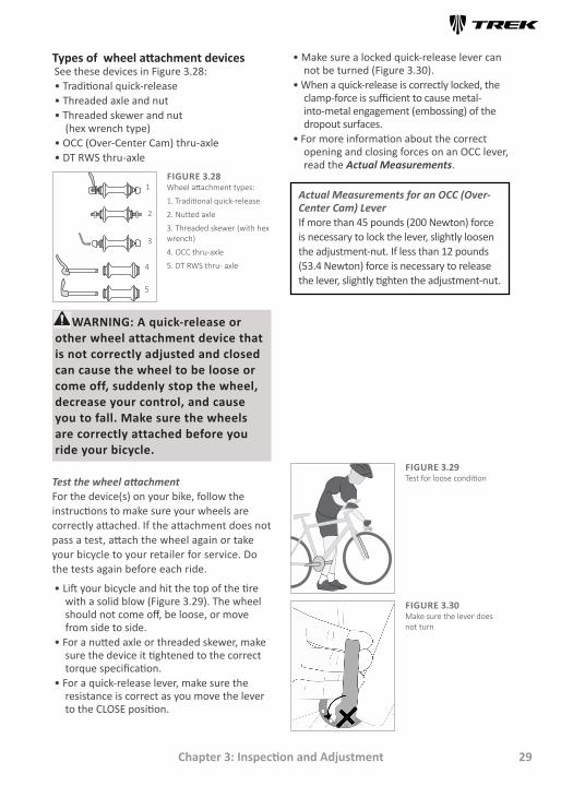
29Chapter 3: Inspection and Adjustment
FIGURE 3.28Wheel attachment types:
1. Traditional quick-release
2. Nutted axle
3. Threaded skewer (with hex wrench)
4. OCC thru-axle
5. DT RWS thru- axle
1
2
3
4
5
WARNING: A quick-release or other wheel attachment device that is not correctly adjusted and closed can cause the wheel to be loose or come off, suddenly stop the wheel, decrease your control, and cause you to fall. Make sure the wheels are correctly attached before you ride your bicycle.
Types of wheel attachment devicesSee these devices in Figure 3.28:• Traditional quick-release • Threaded axle and nut• Threaded skewer and nut
(hex wrench type)• OCC (Over-Center Cam) thru-axle • DT RWS thru-axle
• Make sure a locked quick-release lever can not be turned (Figure 3.30).
• When a quick-release is correctly locked, the clamp-force is sufficient to cause metal-into-metal engagement (embossing) of the dropout surfaces.
• For more information about the correct opening and closing forces on an OCC lever, read the Actual Measurements.
Test the wheel attachmentFor the device(s) on your bike, follow the instructions to make sure your wheels are correctly attached. If the attachment does not pass a test, attach the wheel again or take your bicycle to your retailer for service. Do the tests again before each ride.
• Lift your bicycle and hit the top of the tire with a solid blow (Figure 3.29). The wheel should not come off, be loose, or move from side to side.
• For a nutted axle or threaded skewer, make sure the device it tightened to the correct torque specification.
• For a quick-release lever, make sure the resistance is correct as you move the lever to the CLOSE position.
FIGURE 3.29Test for loose condition
FIGURE 3.30Make sure the lever does not turn
Actual Measurements for an OCC (Over-Center Cam) LeverIf more than 45 pounds (200 Newton) force is necessary to lock the lever, slightly loosen the adjustment-nut. If less than 12 pounds (53.4 Newton) force is necessary to release the lever, slightly tighten the adjustment-nut.

30
Trek Bicycle Owner’s Manual
Chapter 3: Inspection and Adjustment
Over-center cam (OCC)A quick-release uses an over-center cam (OCC). The cam is inside the lever and the skewer passes inside the hollow axle of the hub (Figure 3.31). With this type of cam mechanism, when you move the lever in the correct motion (Figure 3.32), the cam effectively shortens the length of the skewer. This provides a high clamp force. However, the cam mechanism requires correct adjustment of the tension and correct motion of the lever.
This type of attachment is quick, secure, and requires no tools. This makes it an ideal method of wheel attachment for most cyclists.
The traditional quick-release design has proliferated into many variations, including the OCC thru axle. Each of the types of lever-operated wheel attachment use an over-center cam. Read these instructions carefully to ensure that you use the over-center cam mechanism correctly. After reading, if you have any questions about the over-center cam on your bicycle, consult your retailer.
Some bicycles that are equipped with a
quick-release lever also have a disc brake. If the bicycle is ridden with the lever incorrectly adjusted or open, and the lever contacts the disc or wheel (Figure 3.33), the front wheel could stop suddenly, causing the rider to fall. Always make sure your wheels are correctly attached, and the attachment mechanisms closed and locked, before riding the bicycle.
FIGURE 3.34Front and rear lever positions to avoid catching obstacles
FIGURE 3.31Quick-release parts
1- Hub
2- Adjustment nut
3- Skewer (inside hub)
4- Centering springs (narrow end toward hub)
5- Lever
12
3
45
FIGURE 3.32Correct lever movement and lever positions
1- Released (OPEN)
2- Adjustment position
3- Locked (CLOSE)1
2
3
FIGURE 3.33One possible result of not closing the quick-release correctly: lever caught in disc of disc brake
Position of the leverWith the over-center cam of either a traditional quick-release or an OCC thru axle, the lever must be in the correct position after it is moved to the CLOSE position. Align the lever so obstacles in the path of the bicycle can not catch the lever (Figure 3.34). Make sure the lever does not touch a bicycle part or an accessory part (such as rack or fenders), which could prevent the over-center cam from closing fully.
Do not simply rotate the lever to achieve the correct position; adjust the assembly according to the instructions. If you need help, take your bicycle to your retailer and ask them to show you how to do this.
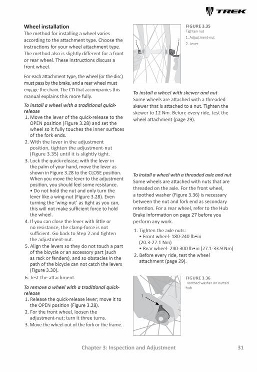
31Chapter 3: Inspection and Adjustment
FIGURE 3.35Tighten nut
1. Adjustment-nut
2. Lever1 2
To install a wheel with skewer and nutSome wheels are attached with a threaded skewer that is attached to a nut. Tighten the skewer to 12 Nm. Before every ride, test the wheel attachment (page 29).
FIGURE 3.36 Toothed washer on nutted hub
1
To install a wheel with a threaded axle and nutSome wheels are attached with nuts that are threaded on the axle. For the front wheel, a toothed washer (Figure 3.36) is necessary between the nut and fork end as secondary retention. For a rear wheel, refer to the Hub Brake information on page 27 before you perform any work.
1. Tighten the axle nuts: • Front wheel- 180-240 lb•in (20.3-27.1 Nm) • Rear wheel- 240-300 lb•in (27.1-33.9 Nm)
2. Before every ride, test the wheel attachment (page 29).
Wheel installationThe method for installing a wheel varies according to the attachment type. Choose the instructions for your wheel attachment type. The method also is slightly different for a front or rear wheel. These instructions discuss a front wheel.
For each attachment type, the wheel (or the disc) must pass by the brake, and a rear wheel must engage the chain. The CD that accompanies this manual explains this more fully.
To install a wheel with a traditional quick-release1. Move the lever of the quick-release to the
OPEN position (Figure 3.28) and set the wheel so it fully touches the inner surfaces of the fork ends.
2. With the lever in the adjustment position, tighten the adjustment-nut (Figure 3.35) until it is slightly tight.
3. Lock the quick-release; with the lever in the palm of your hand, move the lever as shown in Figure 3.28 to the CLOSE position. When you move the lever to the adjustment position, you should feel some resistance. • Do not hold the nut and only turn the lever like a wing-nut (Figure 3.28). Even turning the ‘wing-nut’ as tight as you can, this will not make sufficient force to hold the wheel.
4. If you can close the lever with little or no resistance, the clamp-force is not sufficient. Go back to Step 2 and tighten the adjustment-nut.
5. Align the levers so they do not touch a part of the bicycle or an accessory part (such as rack or fenders), and so obstacles in the path of the bicycle can not catch the levers (Figure 3.30).
6. Test the attachment.
To remove a wheel with a traditional quick-release1. Release the quick-release lever; move it to
the OPEN position (Figure 3.28).2. For the front wheel, loosen the
adjustment-nut; turn it three turns.3. Move the wheel out of the fork or the frame.

32
Trek Bicycle Owner’s Manual
Chapter 3: Inspection and Adjustment
After the wheel is secure, you can pull the handle out on the axle (Figure 3.38) and rotate the handle to reposition it in your preferred position.
FIGURE 3.38Pull DT RWS lever out to reposition
To install a wheel with a thru-axleThere are several types of thru-axles (Figure 3.37). The following instructions explain how to use the two types of thru-axles used with Trek forks. For information about the thru-axle on a suspension fork, refer to the fork manufacturer’s web site, see the CD, or consult your retailer.
FIGURE 3.37Thru axle
Over-Center CamThis type of thru-axle works like a traditional quick-release, but without the adjusting nut.
To secure a wheel: With the lever in the adjustment position, tighten the axle until snug. Then flip the lever to the CLOSE position, just like a quick-release. Like with a quick-release, you should feel some resistance about half way between the OPEN position and CLOSE position. Before every ride, test the wheel attachment (page 29).
If the closed lever is not in a good location, do not adjust the closing force. Instead, reposition the lever; take the bike to your retailer for service.
DT RWSThis type of thru-axle has a handle, not a lever; it is not a quick-release. The axle works like a screw, and the handle works like a wrench to tighten the screw.
To secure a wheel: Instead of flipping the lever to close, you simply rotate the handle until fully tight, a minimum of 15 Nm. Before every ride, test the wheel attachment (page 29).
Carbon composite wheelsIf your bicycle has carbon composite clincher rims, do not overinflate the tires. Regardless of the inflation recommendation written on the tire, Bontrager carbon clincher rims have a maximum inflation rating of 120 psi (8.3 bar).
Use only approved brake padsBontrager carbon rims require special brake pads to prevent heat fade, work properly in wet conditions, and avoid premature wear in wet, abrasive conditions. In addition, incorrect pads can create excessive heat on the rim, which can cause damage to the carbon composite. Only use approved brake pads with Bontrager carbon composite rims. The list of approved pads changes, so check with your retailer for approved pads. Other pads, even though they may claim carbon compatibility, must not be used.
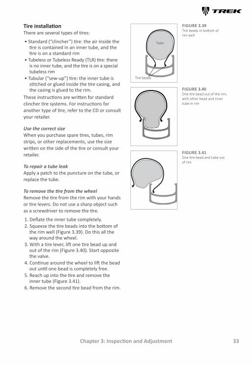
33
Tire installationThere are several types of tires:
• Standard (“clincher”) tire: the air inside the tire is contained in an inner tube, and the tire is on a standard rim
• Tubeless or Tubeless Ready (TLR) tire: there is no inner tube, and the tire is on a special tubeless rim
• Tubular (“sew-up”) tire: the inner tube is stitched or glued inside the tire casing, and the casing is glued to the rim.
These instructions are written for standard clincher tire systems. For instructions for another type of tire, refer to the CD or consult your retailer.
Use the correct sizeWhen you purchase spare tires, tubes, rim strips, or other replacements, use the size written on the side of the tire or consult your retailer.
To repair a tube leakApply a patch to the puncture on the tube, or replace the tube.
To remove the tire from the wheelRemove the tire from the rim with your hands or tire levers. Do not use a sharp object such as a screwdriver to remove the tire.
1. Deflate the inner tube completely. 2. Squeeze the tire beads into the bottom of
the rim well (Figure 3.39). Do this all the way around the wheel.
3. With a tire lever, lift one tire bead up and out of the rim (Figure 3.40). Start opposite the valve.
4. Continue around the wheel to lift the bead out until one bead is completely free.
5. Reach up into the tire and remove the inner tube (Figure 3.41).
6. Remove the second tire bead from the rim.
Chapter 3: Inspection and Adjustment
FIGURE 3.41One tire bead and tube out of rim
FIGURE 3.39Tire beads in bottom of rim well
Tube
Tire beads
FIGURE 3.40One tire bead out of the rim, with other bead and inner tube in rim

34
Trek Bicycle Owner’s Manual
Chapter 3: Inspection and Adjustment
Table of inflation pressures
PSI BAR kPa PSI BAR kPa
35 2.38 238 80 5.44 544
40 2.72 272 85 5.78 578
45 3.06 306 90 6.12 612
50 3.40 340 95 6.46 646
55 3.74 374 100 6.80 680
60 4.08 408 105 7.15 715
65 4.42 442 110 7.48 748
70 4.76 476 115 7.83 783
75 5.10 510 120 8.17 817
FIGURE 3.42One tire bead and tube out of rim
FIGURE 3.43One tire bead out of the rim, with other bead and inner tube in rim
FIGURE 3.45Tire beads seated in rim hooks, with inner tube inside rim
To install a tire on the wheel1. Follow the Inspection procedures in the
Wheels section to check the rim, rim strip, and tire. Also check the inside of the tire.
2. Inflate the tube until it begins to take shape.
3. Place the tube in the tire. 4. Insert the valve stem through the hole
in the rim. 5. With only your hands, install the first bead
onto the rim (Figure 3.42). Start at the valve stem.
6. Push the tire and tube over so the tube is inside the rim (Figure 3.43).
7. With only your hands, push the second bead into the rim. Start at the valve stem. Do not pinch the tube between the rim and the tire (Figure 3.44).
8. Push the base of the valve stem up into the tire so that it is not caught between the tire bead and the rim.
9. Inflate the tire to about half pressure and then check that the tire bead is properly seated in the rim (Figure 3.45).
10. Deflate the tire again. This will help avoid any pinch of the tube.
11. Inflate the tire to the pressure indicated on the side of the tire. Do not over-inflate.
FIGURE 3.44Do not pinch tube between bead and rim

35Chapter 3: Inspection and Adjustment
Crankarms and bottom bracketThe crankarms connect the pedals to the bottom bracket. They transmit power from the rider to the rear wheel, and with a coaster brake they actuate the brake.
The length of some crankarms can be adjusted by moving the pedals into a second position: see the Pedals section.
The bottom bracket is the bearing system that allows the crankarms to turn in the frame. Each month check the bottom bracket.
To check the bottom bracket adjustment1. Lift the chain from the chainrings.2. Turn the crankarms so that they are parallel
to the seat tube.3. Put one hand on the crankarm and one hand
on the seat tube. Try to move the crankarm toward and away from the seat tube.
4. Turn the crankarms.If the crank feels or sounds loose, the movement stops suddenly, or you hear a grinding noise, do not ride your bicycle. The adjustment of the bottom bracket requires special tools and training. Take your bicycle to your retailer for service because only your retailer should adjust bearings.
PedalsThe pedals hold your feet so that you can rotate the crankarms. Check the pedals each month.
To check the pedal bearing adjustment1. While holding the crankarm with one hand,
try to move the pedal up and down. 2. Turn the pedal. If the pedals move on the crankarms or do not turn smoothly, do not ride your bicycle. The adjustment of the pedal bearings requires special tools and training. Take your bicycle to your retailer for service because only your retailer should adjust bearings.
Training wheelsBefore adjusting the training wheels, make sure the tires are correctly inflated.
1. Put the bicycle on a flat, smooth surface.2. Loosen the rear axle-nuts. 3. Hold the bicycle up straight, and adjust the
distance between the training wheels and the ground to approximately 1/4” (6 mm). Make the distance the same on both sides of the bicycle.
4. Adjust the tension of the chain, and tighten the axle-nuts. Use the procedures in the Wheels section.
CablesOn a bicycle with a shifter or hand brake, a cable connects the control lever to the item it controls. Before every ride, make sure the cables and housing are properly secured to the frame or fork so that they cannot interfere or get caught on moving parts. Each month check the cables for problems: kinks, rust, broken strands, or a frayed end. Also check the cable-housing for loose wire strands, bent ends, cuts, and worn areas. If there is a problem with a cable or housing, do not ride your bicycle. Follow the instructions to replace the cable, or take your bicycle to your retailer for service.
HeadsetThe headset is the bearing system that allows the handlebar and fork to turn. Each month check the headset.
To check the headset adjustment1. Apply the front brake while you rock the
bicycle forward and rearward. 2. Lift the front wheel off the ground. Slowly turn
the fork and handlebar to the right and left. If the fork moves in the frame or does not turn smoothly, do not ride your bicycle. The adjustment of the headset requires special tools and training. Take your bicycle to your retailer for service because only your retailer should adjust bearings.

36
Trek Bicycle Owner’s Manual
Chapter 3: Inspection and Adjustment
SuspensionYou can adjust the performance of your bicycle suspension to suit your weight, riding style, and personal preference. Each suspension system is different. For suspension setting recommendations, go to the Trek suspension setup on our web site: www.trekbicycles.com/suspension.
You should not be able to fully compress the suspension. If the suspension is fully compressed, its movement will stop suddenly and could decrease your control.
If you adjust your suspension, your bicycle will turn and stop differently. After you adjust the suspension, carefully test ride your bicycle in a low traffic area until you know its performance.
Each month, check the bolts on all suspension parts: attachment bolts and pivot bolts.
Luggage carriersLuggage can only be carried safely on a bike when in or on a luggage carrier. However, not all Trek bicycles are compatible with a luggage carrier. If you are not sure, ask your retailer.
A luggage carrier is to be attached to threaded frame fittings with 5mm screws that are long enough to provide at least 5mm of thread engagement. Tighten screws to 2.3-2.9 Nm (20-25 lb*in). Check the screws once a month.
As with any other bike part, do not modify the luggage carrier. Do not attach a child carrier, trailer, and anything else unless the luggage carrier specifically permits this and the weight limits are followed.
Loading a luggage carrierDo not overload the luggage carrier. The maximum weight is printed on the carrier.Also do not overload the bicycle; see Use Conditions, pages 13-14.
Place weight evenly, so that it is balanced on both sides of the bike. Also, do not overload one end (front or rear) of the bike. Additional
To tighten pedalsThe right pedal is threaded into the crankarm in the usual direction, but the left pedal is left-hand threaded. Tighten pedals into the crankarms to 350-380 lb•in (40.2-42.9 Nm).
To adjust the release force on clipless pedalsRefer to the manual that came with your pedals or the CD that came with this manual, or consult your retailer.
ChainThe chain connects the chainring (and crankarms) to the rear wheel. On a bicycle that does not have a rear derailleur, correct chain tension is required to prevent the chain from falling off. Each month, check the chain.
To adjust the chain tensionIf your bicycle has adjustable dropouts or a bottom bracket eccentric, refer to the CD for instructions or consult your retailer.
1. Slightly loosen the rear wheel axle nut on one side of the wheel, then on the other side of the wheel. If you fully loosen the axle nut on one side before you loosen the other axle nut, you can cause the bearings to come out of adjustment.
2. Slide the wheel rearward to tighten the chain. Put the wheel in the center of the frame.
3. Complete the wheel installation (see Wheels).
ReflectorsEvery three months, make sure all the fasteners holding the front, rear, pedal, and wheel reflectors are tight. Check that front and rear reflectors are oriented so their reflective surfaces are perpendicular to the ground, and that all reflective surfaces are clean and in good condition. The front reflector should point directly forward, and the rear should point directly back. Wheel reflectors should be tight and snug against supporting spokes to prevent rattling. Make sure the reflectors are not obstructed by your gear or clothing.
37Chapter 3: Inspection and Adjustment
weight on your bike may affect the steering and will increase braking distances.
Make sure luggage is attached securely, and that no straps or other parts can become entangled in the wheels or other moving parts.
Make sure that luggage does not interfere with or block lights and reflectors.
AccessoriesIn addition to the parts already discussed in this chapter, your bicycle might have accessories such as fenders, lights, chainguard, training wheels, or kickstand. Each month, check the accessories to make sure they are correctly attached. If the part is loose or not in alignment, adjust or tighten the part, or take your bicycle to your retailer for service. Find more detailed information and instructions on the CD that accompanies this manual.
To install a light bulbThe bulb has markings that indicate the correct voltage. When purchasing spares or replacements, take the bulb with you to the store to make sure you purchase the correct bulb for your light.
1. Find the lens set-screw on the rear of the light. 2. Turn the screw counterclockwise. Remove it. 3. Turn the lens one quarter-turn clockwise.
Pull the lens assembly off of the bulb-attachment.
4. Turn the bulb counterclockwise. Remove it. • Be careful not to crush the glass of the bulb. Do not dislodge the wire in the base of the bulb-attachment.
5. Turn a new bulb in until it is slightly tight.6. Put the lens on the bulb-attachment.
Turn the lens one quarter-turn counterclockwise.
7. Put the lens set-screw in the rear of the light. Tighten the screw.
Make sure the new bulb operates. If it does not, check the wires for correct position, and make sure that the new bulb does not have damage.
Frameset (frame and fork)The frame is the backbone of the bicycle, the part to which other parts, including the fork, attach. The fork holds the front wheel and is controlled or steered by the handlebar. The maintenance of the frameset is critical to your safety. Before attempting any work on the frame, fork, or components; or installing any accessory; read the section Warning about mechanical work on page 11.
The frame or fork may be constructed from a variety of materials, including steel alloy, aluminum alloy, or carbon composite. If your bicycle is constructed with carbon composite, read the section Carbon composite on page 12.
In addition, the frame or fork may contain suspension components. If your bicycle has suspension, refer to the Suspension section of this chapter.
General informationBontrager forks are not compatible with any mechanism that clamps around the fork blade, with the exception of bicycle computer sensors. If you are unsure of what items can be attached to this fork, consult your retailer.
Carbon composite frames must always be fitted with a chainstay guard or chain keeper to protect against damage in case of chainsuck or over-shifting past the inner chainring.
Excessive heat, such as that used in powder coating, or any open flame, may damage the adhesive which joins the frame parts on some framesets. Do not exceed 150°F (65°C) exposure to your frame.
A frameset with a round or cylindrical seatpost uses one of three common sizes of seat lugs designed to accept seatposts with 27.12 to 27.20 mm, 29.12 to 29.2 mm, or 31.45 to 31.60 mm outer diameter. The seatpost should be measured for conformity to this tolerance prior to installation. Use correct lubrication (see page 40) to prevent seizing of the seatpost to the seat lug or tube.

38
Trek Bicycle Owner’s Manual
Chapter 3: Inspection and Adjustment
the headset bearings are serviced. Because this requires disassembling the headset bearings, this procedure requires special tools and skills. If you do not have the training, take your bicycle to your retailer for inspection.
To completely inspect the fork1. Remove the fork from the bicycle.2. Thoroughly clean the steerer and fork
crown area.3. Look for signs of fatigue or impact damage.
Adjustment of a frame or forkAn aluminum or carbon composite frame or fork and their aluminum parts (like dropouts) are not as ductile as steel. Never attempt to make adjustments to a part by bending or twisting it. Readjustment of aluminum or composite material is not possible. If the frame has been damaged, take the bicycle to your retailer for evaluation, and possible repair or replacement.
Repairing a carbon composite frame or fork Accidents happen, both when riding a bicycle and when not riding (e.g. when transporting on the car, storing in the garage, or at other times). Replacing a damaged carbon part can be expensive. To help with that expense, Trek provides a reduced-cost replacement program we call the Trek Loyalty Program. See your retailer for details.
Trek does not recommend the repair or patch of a damaged carbon tube or part. To explain why, let’s use a bicycle frame as an example. A modern Trek carbon bicycle frame doesn’t work like a collection of tubes and lugs; it’s designed to function as an integrated unit. This integration allows the structure to distribute and share forces across the entire structure. In other words, force applied to the down tube will be spread out so that all tubes get a chance to absorb it and the force on the down tube is greatly reduced. This is the key to making a lightweight frame that is still stiff and strong enough for top-level competition.
When cleaning frame parts, do not use solvents or harsh chemicals. Remove road film with a soft rag and a mild detergent and water solution. Use of industrial solvents for cleaning or paint removal may damage not only the paint but also the adhesive which joins the frame parts.
Tolerances for press fits and thread fits are critical. Pressing a part which is too large, or misaligned, may break the frame or part. Over-tightening a threaded fastener may ruin the threads or break the part. Be sure bottom bracket and rear derailleur threads are clean and well greased before insertion. Start threads by hand, not with a wrench.
Removing paint from a frame requires special techniques, so should only be done at the factory. Consult your retailer for more information.
On Speed Concept models, the fork and the frame fit very tightly to reduce aerodynamic drag. Avoid turning the aero-bar to an extreme angle because the fork and frame can contact, possibly causing damage to the finish.
For further information about the inspection, care, and maintenance of your frame and fork, read Chapter 1.
InspectionBefore each ride carefully inspect your frameset (frame and fork) for signs of stress or fatigue. Scratches, cracks, dents, deformation, or discoloration are signs of stress. If any part shows signs of damage, stress, or fatigue, replace the part before riding the bicycle.
Each month, inspect the chainstay guard on your frame. Make sure the chainstay guard is installed correctly and securely attached. If it is dislodged or damaged, have your retailer install a replacement.
Each year, completely inspect the fork. Take the fork out of the bicycle and inspect the steerer and crown, which are partially hidden inside the frame. This inspection can be completed when

39
Adding a carbon ‘patch’ to a frame tube changes the tube’s stiffness and shock absorption characteristics. This change in stiffness can affect the tube’s ability to absorb or transfer impact energy. In an impact, an overly-stiff patched tube might abruptly transfer all the force to another part of the frame. When the force is abruptly transferred from the first part to the second part of the bicycle, the resulting overload can cause the second part to break.
Due to the nature of bicycle crashes and impacts, it is impossible to predict exactly how forces will be absorbed or transferred. So for your safety, Trek recommends that Trek carbon composite frames or forks NOT be repaired, by anyone.
Also note that a repair is a modification, and making a modification to the frame will void the warranty (see page 11, Modifications to Your Bicycle Can Make it Unsafe and the warranty at trekbicycles.com).
Frame stickerYour frame has a sticker (Figure 3.46). Do not remove the sticker; it contains important safety information that you or anyone riding the bicycle should read.
FIGURE 3.48DuoTrap integrated computer mount on chainstay for speed and cadence sensors
IsoSpeedSome frames include an IsoSpeed decoupler, a mechanism that allows the frame to provide vertical compliance without compromising pedaling efficiency. This mechanism is located at the junction of the top tube and seat tube (Figure 3.47). With IsoSpeed, the saddle is more comfortable, but all your pedaling energy goes to the rear wheel.
The IsoSpeed mechanism is designed to last the lifetime of the bicycle without service. Do not lubricate it. Keep it clean with water and a soft cloth.
If the mechanism makes noise or exhibits lateral play, the design allows easy replacement of the mechanism. Take your bicycle to your retailer for service.
Chapter 3: Inspection and Adjustment
FIGURE 3.46Frame sticker
DuoTrapSome frames have DuoTrap, a special cavity that can house the wireless sensor for a bicycle computer (Figure 3.48). Ask your retailer about DuoTrap-compatible computers.
FIGURE 3.47IsoSpeed decoupler

40
Trek Bicycle Owner’s Manual
Chapter 4: LubricationThis section shows the parts that you should lubricate, the frequency of service, and brief instructions. See your retailer for recommended grease or oil. If more instructions are necessary, see other sections of this manual or consult your retailer.
To service bearings, special tools and training are necessary, so only your retailer should do this. Some bearings are permanently sealed and do not require new grease each year.
StemEach year apply lubricant to the stem.
To apply lubricant to a direct-connect stem, adjustment of the headset bearings is necessary. Only your retailer should do this.
To apply lubricant to a quill stem1. Remove the stem from the frame. 2. Clean the used grease from the stem. 3. Apply a thin layer of grease to the section
of the stem-quill that will be put into the frame. Also apply grease to the stem wedge.
4. Install the stem.
SeatpostEach year apply lubricant. Use the procedure for your frame and seatpost materials:
For a metal seatpost in a metal frame1. Loosen the seatpost binder bolt, or release
the quick-release, and remove the seatpost from the frame.
2. Clean the used grease off the seatpost. 3. Apply a thin layer of grease to the section
of the seatpost that will be in the frame. 4. Put the seatpost into the frame.5. Adjust the saddle to the correct height and
align it. Tighten the seatpost binder-bolt or lock the quick-release.
Chapter 4: Lubrication
Special frame attachmentsSome bicycles include one or more of a unique attachment point which allows you to use custom accessories. Consult your retailer for details.
For example, some frames include a kickstand attachment (Figure 3.50).
For another example, Speed Concept frames provide attachment points for a “Speed Box” on the top tube. This attachment might create a slight obstruction that is not allowed by the CPSC (Consumer Product Safety Commission) standards on a bicycle at the time of sale, so we do not attach one as standard equipment.
Hidden fender mountsSome frames include hidden mounts for fenders (Figure 3.49). Ask your retailer for the parts necessary to mount compatible fenders.
FIGURE 3.49Hidden fender mount
FIGURE 3.50Kickstand attachment

41Chapter 4: Lubrication
For a carbon composite seatpost, or any seatpost in a carbon composite frame1. Loosen the seatpost binder-bolt, or release
the quick-release, and remove the seatpost from the frame.
2. Clean the seatpost and the inner surface of the seat tube with a soft cloth and clean water.
3. Let the seatpost dry. Then put it into the frame.
4. Adjust the saddle to the correct height and align it. Tighten the seatpost binder bolt.
Bottom bracketEach year, replace the grease in the bottom bracket bearings. To service bearings, special tools and training are necessary, so only your retailer should do this.
ChainEach month, apply lubricant to the chain. Always place a rag behind the chain to prevent lubricant on other parts of the bicycle. After you apply lubricant, wipe off the excess with a rag.
PedalsEach year, replace the grease in the pedal bearings. To service bearings, special tools and training are necessary, so only your retailer should do this.
Each year replace the grease on the pedal axles where they thread into the crank arms. There are right and left pedals, usually identified with a letter on the end of the pedal axle or on the wrench flats.
1. Remove the pedal-axles from the crankarms; turn the right pedal-axle counterclockwise, but turn the left pedal-axle clockwise.
2. Apply a thin layer of grease on the threads.3. Install the pedals on the correct side; put
the right pedal on the right crankarm and the left pedal on the left crankarm.
4. Tighten the pedal-axles.
DerailleursEach month, apply lubricant to all pivot points on the front and rear derailleurs, together with the derailleur pulleys on the rear derailleur.
HeadsetEach year, replace the grease in the headset bearings. To service bearings, special tools and training are necessary, so only your retailer should do this.
Brakes and brake-leversEach three months apply lubricant to the brake-lever pivots and brake arm fixing pivots.
WheelsEach year, replace the grease in the wheel bearings. To service bearings, special tools and training are necessary, so only your retailer should do this.
Each year, apply lubricant to wheel quick-releases. Apply two or three drops of synthetic lubricant or a light oil where the quick-release lever turns in the quick-release body.
Suspension forksEach month, lubricate your suspension fork. Refer to the instructions on the CD, or consult your retailer.
Each year, replace the oil in your suspension fork. To replace the oil, special tools and training are necessary, so only your retailer should do this.
Rear suspensionDo not apply lubricants to the shock or the pivots of your full-suspension bicycle. If the shock or pivots make noise or do not operate smoothly, take the bicycle to your retailer for service.

42
Trek Bicycle Owner’s Manual
For more instructionsIf you need more instructions about your bicycle or the servicing of bicycles, there are many resources in your community.
Consult your bicycle retailer. They have extensive experience with bicycles and rides in your community. They can answer your questions and help you in your search for areas in which to enjoy your new bicycle. Most retailers sell repair manuals and books about cycling.
Visit your public library. Most libraries have books about how to ride, how to race, bicycle safety, bicycle maintenance, and more.
Look on-line. The best on-line resource for your bicycle can be found on the CD that accompanies this manual. With internet access, you can go directly from the CD to our web site. The CD also links to some of the companies that make the parts of your bicycle.
WarrantyYour bicycle is covered by a warranty. For the specifics of this warranty, visit our web site: www.trekbicycles.com
L
CablesApply lubricant to a cable when you install it.
To install a cable in a cantilever brake, special tools and training are necessary, so only your retailer should do this.
To install a cable1. Before you remove the used cable, note its
path on the frame. Loosen the cable-clamp bolt, and remove the worn cable.
2. Apply grease to the new cable where it passes through housing or guides. Install the new cable on the same path as the used cable.
3. Make sure the leaded end of the cable is installed correctly in the lever. Make sure the housing is correctly installed in the housing stop of the lever. • If necessary when you install a cable in a brake, adjust the brake again.
4. Turn the barrel-adjuster clockwise so that the threads on the barrel-adjuster do not show. • For a derailleur cable, put the shift-lever in the position with the least cable tension. • For a brake cable, hold the brake closed while you do the subsequent step.
5. Tighten the cable-clamp bolt to 52-69 lb•in (6-8 Nm).
6. Cut the cable so that no more than 2” (51 mm) extends through the clamp-bolt.
7. Put a metal cap or put a bit of solder on the end of the cable to prevent a frayed cable.
8. Use the instructions for adjustment.