important safety guide
TRANSCRIPT

Installation manualMatrix front bumperProduct number: X475XApplication: 2021 Ford F150

IMPORTANT SAFETY GUIDE | Your safety and the safety of others is very important.
SAFETY PRECAUTIONS
In order to help you make informed decisions about safety, we have provided the following warnings, safety precautions, installation instructions, and other important information to alert you to potential hazards that could hurt you or others.
Please do a job safety analysis before each task to identify potential hazards for your situation and remove/protect against them. Use own good judgment and take your time.
• Failure to observe the following warnings and instructions provided in this manual could lead to severe injury and/or death.
• For professional installation only. Careless installation and/or operation can result in serious injury, death, and/or equipment damage. All liability for installation and use rests with the user or consumer.
WARNINGS
• Always remove jewelry and wear eye protection.
• Always use extreme caution when jacking up a vehicle for work. Set emergency brake and use tire blocks. Locate and use the vehicle manufacturers designated lifting points. Use jack stands.
• Always use appropriate and adequate care in lifting components into place.
• Always ensure components will remain secure during installation and operation.
• Always wear safety glasses when installing this kit. A drilling operation will cause flying metal chips. Flying chips can cause serious eye injury.
• Always use extreme caution when drilling a vehicle. Always disconnect power before welding. Thoroughly inspect the area to be drilled (on both sides of material when possible) prior to drilling, and relocate any objects that may be damaged.
Check packaged materials immediately upon arrival to ensure that all listed parts are included and undamaged.
Read and understand all warnings, safety precautions, and instructions before installing this product.
SENSORS FIELD OF VIEW MAY BE ALTERED WITH USE OF THE REPLACEMENT BUMPER.
• Fab Fours, Inc. only approves installing this product according to these written instructions with the hardware provided. Failure to install according to these instructions will invalidate the warranty. This includes, but is not limited to, using alternative installation methods, hardware, or materials.
• This product is for off road use only.
• Always use extreme caution when welding a vehicle. Thoroughly inspect the area to be welded (on both sides of material when possible) prior to welding, and relocate any objects that may be a fire hazard. When welding in a cab, make sure the interior surfaces are covered (e.g., welding blanket) and a fire extinguisher is at hand.
• Always use extreme caution when cutting and trimming during fitting.
• Always tighten all nuts and bolts securely per installation instructions.
• Always route electrical cables carefully. Avoid moving parts, components that become hot, and rough or sharp edges.
• Always insulate and protect all exposed wiring and electrical terminals.
• Perform regular inspections and maintenance on mounts and hardware.

Tabl
e of c
onte
nts SAFETY / DISCLAIMER
TABLE OF CONTENTSA MESSAGE FROM THE OWNERGETTING STARTEDPROVIDED MATERIALDISASSEMBLYINSTALLATIONCONTACT
2345671114

A message from the owner
Fab Fours’ was born out of a passion for customizing vehicles and a love of the outdoors. Our engineering team uses the latest 3D design software to turn new product ideas into reality. In our factory, designs come to life with the combination of cutting edge technology for metal cutting and forming and an American workforce that puts its’ heart and pride into every product.
From design and manufacturing, to quality and delivery, Fab Fours’ mission is to be the market leader for steel truck and jeep accessories. We make sure a quality product is delivered on time, more than expected, better than expected to our customers.
Enjoy your new Fab Fours product. Welcome to the family!
Greg HiggsFounder, Fab Fours

5
Before you begin the installation process of your new Fab Fours product, we suggest laying out all materials and parts on a pad or protective surface.
Failure to fully account for all components before beginning installation may leave vehicle immobile until part is acquired. Refer to the next pages as an inventory check.
Getting started
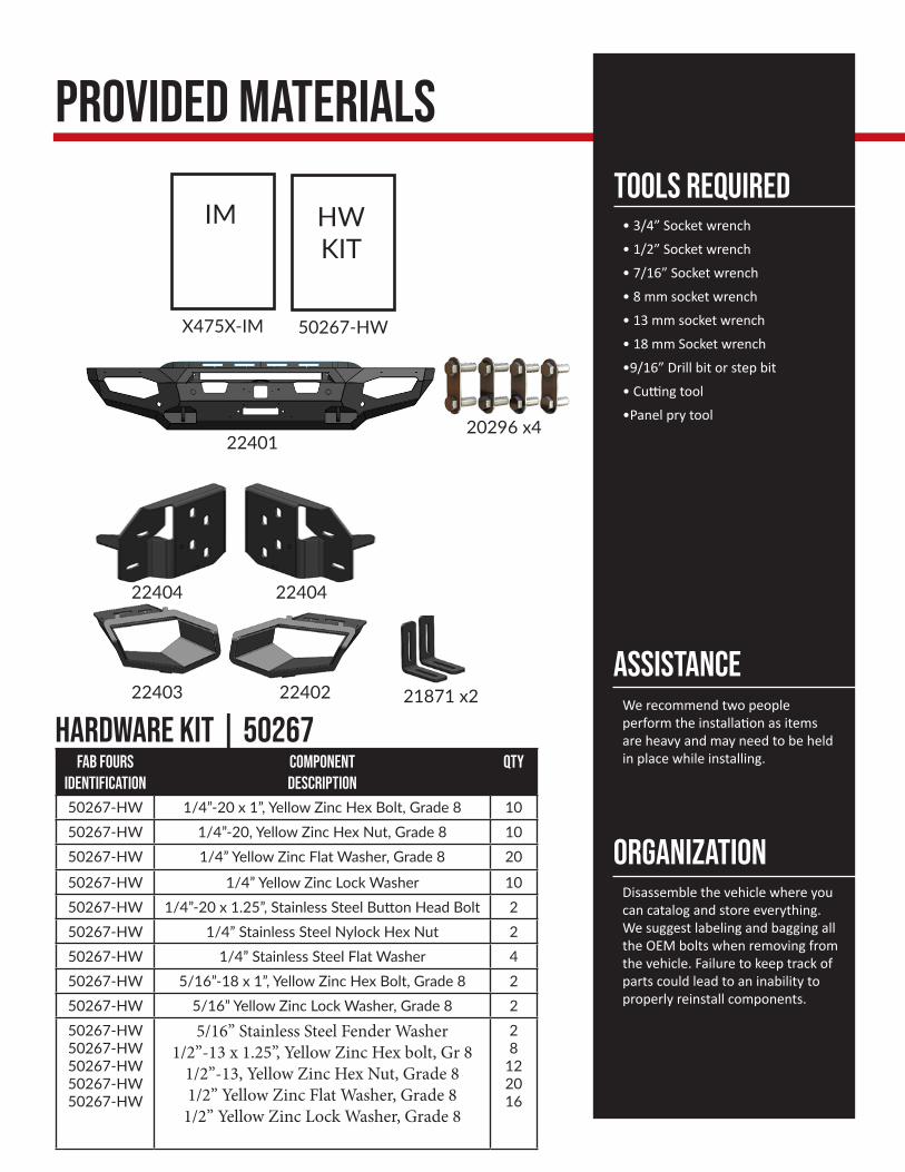
Provided materials
• 3/4” Socket wrench
• 1/2” Socket wrench
• 7/16” Socket wrench
• 8 mm socket wrench
• 13 mm socket wrench
• 18 mm Socket wrench
•9/16” Drill bit or step bit
• Cutting tool
•Panel pry tool
TOOLS REQUIRED
Disassemble the vehicle where you can catalog and store everything. We suggest labeling and bagging all the OEM bolts when removing from the vehicle. Failure to keep track of parts could lead to an inability to properly reinstall components.
Organization
We recommend two people perform the installation as items are heavy and may need to be held in place while installing.
Assistance
X475X-IM
IM
50267-HW
HWKIT
22404
2240222403
Hardware kit | 50267Fab Fours
IdentificationComponent Description
QTY
50267-HW 1/4”-20 x 1”, Yellow Zinc Hex Bolt, Grade 8 1050267-HW 1/4”-20, Yellow Zinc Hex Nut, Grade 8 1050267-HW 1/4” Yellow Zinc Flat Washer, Grade 8 20
50267-HW 1/4” Yellow Zinc Lock Washer 1050267-HW 1/4”-20 x 1.25”, Stainless Steel Button Head Bolt 250267-HW 1/4” Stainless Steel Nylock Hex Nut 250267-HW 1/4” Stainless Steel Flat Washer 450267-HW 5/16”-18 x 1”, Yellow Zinc Hex Bolt, Grade 8 250267-HW 5/16” Yellow Zinc Lock Washer, Grade 8 250267-HW50267-HW50267-HW50267-HW50267-HW
5/16” Stainless Steel Fender Washer1/2”-13 x 1.25”, Yellow Zinc Hex bolt, Gr 8
1/2”-13, Yellow Zinc Hex Nut, Grade 81/2” Yellow Zinc Flat Washer, Grade 8
1/2” Yellow Zinc Lock Washer, Grade 8
28
122016
22401
22404
21871 x2
20296 x4

7
1. Locate and disconnect the wire harnesson the passenger side frame. (Figure 1)
2. Use an 8mm socket wrench to removethe two bolts on both sides of the truckthat attach the valence to the fender well.Carefully pull the valence off the truck bydisconnecting the clips along the top of thevalence. (Figure 2)
3. From underneath the truck, use an 18mmsocket wrench to remove the three (3)mounting nuts from both sides of the trucksframe horns. (Figure 3)
Figure 1
Figure 2
DisassemblyNOTE: Save all OEM parts until installation is complete!
Figure 3

Figure 4
4. If you intend to install a winch or 30” light bar you will need to remove the front air dam skirt from the lower louver system. Use a body pry tool to disconnect the clips long the air dam boarder. The air dam skirt will not be reinstalled. (Figure 4)
Figure 6
Figure 5
5. Use an 8mm socket wrench to remove thefour bolts holding the lower louver systemto the frame. Use a cutting tool to trim thefrom face off of the louver system. Reinstallthe louver system onto the frame again.(Figure 5-6)

9
9. Use an 18mm socket wrench to remove the two (2) bolts holding the tow hooks onto the frame. Remove the tow hooks form the truck. (Figure 9)
Figure 8
Figure 9
6. With the OEM bumper removed: Remove the mount plates, fog light bracket brackets and wing structure to access the wiring harness and sensor housings. Carefully remove the sensor from their housings by gently pushing the housing clips outward while pushing the sensor out of the bumper. (Figure 7)
7. Remove and label the sensor housings by compressing the locking clips and pushing the housing of the bumper shell. (Figure 8)
Figure 8
8. If your truck is equipped with Adaptive Cruise Control (ACC) remove the sensor from the OEM bumper and set aside for later install.

10. If your truck is equipped with ACC: remove the ACC sensor form its bracket. Trim the bracket at the line shown below. Reattach the ACC sensor to the trimmed bracket. (Figure 10-11)
Figure 10
Figure 11
Figure 12
11. Take the sensor housings removed during step 7 and install them into their respective holes making sure to put the correct housing back its to OEM location. (Figure 12)

11
Figure 14
14. Place the ACC sensor on the sensor mounts and use the provided 1/4” yellow zinc hex head bolts with flat/lock washers and nuts to secure it in place (50267-HW). (Figure 15)
Figure 15
12. Run the wire harness through the bumper making sure to keep the plug on the passenger side. Carefully install each sensor into its respective housings. Use the provided epoxy packs to secure the housings and sensors in place. (Figure 13)
13. Cut and drill the provided plastic sheet to cover the ACC sensor hole using the 1/4” stainless steel button head bolts with flat washers and lock nuts (50267-HW). (Figure 14)
Figure 13
installation

15. If installing a 30” Single row light bar: Do so now using the provided L-brackets (21871) along with (2) 1/4” yellow zinc hex bolts, flats/lock washers and nuts to attach the light bar to the mounting structure (50267-HW). (Figure 16)
Figure 16
16. With assistance, hold the bumper up to the mounts and use the 1/2” yellow zinc nuts, flat and lock washers (50267-HW). (Figure 17)
Figure 17

13
17. Install the driver side and passenger side light boxes (22402-22403) using the 5/16” yellow zinc bolts with fender washers and lock washers (50267-HW). Slide the light box into the upper tabs and then bolt the lower flange in place to secure it. (Figure 18)
Figure 18
18. Fully tighten all mounting hardware and plug in all the sensors and harnesses.

Fab Fours Inc.2213 Industrial Park RoadLancaster, SC 29720
Phone: (866) 385-1905Fax: 866-574-1423Email: [email protected]
Contact information

“If you’re looking for more of the same,Then you’ve come to the wrong place.”
- Greg Higgs