importing 3d assemblies - matrix tsl · importing 3d assemblies ... systems that offers a flowchart...
TRANSCRIPT

Importing 3D Assemblies Guide

2
Importing 3D Assemblies Guide
Copyright © 2016 Matrix Technology Solutions Ltd.
Flowcode is primarily a software package for the design of microcontroller systems that offers a flowchart based method of programming. For those new to programming, this is ideal as the visual implementation of flowcharts can be easier to understand. For those with programming experience, Flowcode offers the distinct advantage of speed, reducing the rapid prototyping stage of development. It is also used for the complete development cycle in many applications.
With advances in technology and in particular the electronics industry, engineers of all disciplines are now expected to understand microcontrollers to some basic level. In Flowcode, engineers can create complex systems in minutes.
Alongside this flowchart method of programming, Flowcode offers a powerful 3D simulator package. This allows users to verify their program before downloading code to hardware. The 3D environment is ideal for electromechanical systems where motors, servos, actuators can all be visually represented. Users can characterise and program 3D electromechanical systems with ease. Alongside these electromechanical components, users can import and characterise 3D systems, such as windmills, car steering racks, electric fans and many more. In fact, Flowcode allows users to simulate almost any electromechanical system. If we haven’t already got a 3D system that suits your needs, you can design your own in a dedicated 3D package and import it into Flowcode.
Flowcode supports the importing of 3D model assemblies in the industry standard formats of STEP, IGES and OBJ. This allows users to create their 3D models in dedicated drawing packages such as Solidworks, Autodesk Inventor or DesignSpark Mechanical and import them into Flowcode. One imported, users can ‘link’ objects to motors, servos and actuators to create their own 3D systems.
In this guide we will walk through the 4 steps required to import and characterise your own 3D model in Flowcode. We will assume you have created a simple fan, and want to simulate the rotation of the object with a DC motor.
Creating your own 3D electromechanical system can be achieved in as little as 4 steps;
1. Create/ obtain the 3D model that you want to simulate in Flowcode
2. Import the model into Flowcode
3. Characterise your model a. Group any common objectsb. Assign links to objects to allow
movement
4. Create your flowchart

3
Importing 3D Assemblies Guide
Copyright © 2016 Matrix Technology Solutions Ltd.
Create/ obtain the 3D model that you want to simulate in FlowcodeFirst users must either create their own 3D system, or obtain a model from elsewhere. We will assume you are creating your own 3D model. There are a few things to remember;
Flowcode offers a 3D simulation environment, however, it is not a dedicated 3D drawing package. You will be simulating high-level electromechanical systems. When creating your own models for simulation, keep them as simple as possible, this will improve the simulation performance within Flowcode. For example, there’s no need to import a 3D model which includes multiple screws, all with a
fine thread pitch and detailed screw head! Either simplify your model resolution, or remove unnecessary elements.
Flowcode supports STEP, IGES, OBJ and STL file formats, however, STL files do not work as assemblies. Save your model in any of the appropriate file formats and remember the saved location.
Note: For STEP files, the STEP 214 file format works best with Flowcode.

4
Importing 3D Assemblies Guide
Copyright © 2016 Matrix Technology Solutions Ltd.
5
Importing 3D Assemblies Guide
Copyright © 2016 Matrix Technology Solutions Ltd.
Import the model into FlowcodeWith your 3D model saved, you can now import it into Flowcode. 3D models are imported by navigating to File->Import 3D Model… (note; you must have an opened flowchart for the import 3D model menu to appear).
The import model dialogue will appear as seen below, where users can import the following file types;
1. .MESH2. .OBJ3. .STEP4. .IGES 5. .STL
If you import an .OBJ, .STL, .STEP or .IGES file, Flowcode will need to convert that file to its native file format. If you import a .MESH file, it will already be in the appropriate file format.
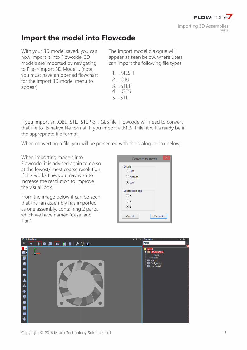
When converting a file, you will be presented with the dialogue box below;
When importing models into Flowcode, it is advised again to do so at the lowest/ most coarse resolution. If this works fine, you may wish to increase the resolution to improve the visual look.
From the image below it can be seen that the fan assembly has imported as one assembly, containing 2 parts, which we have named ‘Case’ and ‘Fan’.

6
Importing 3D Assemblies Guide
Copyright © 2016 Matrix Technology Solutions Ltd.
Characterise you modelWith your 3D model now in Flowcode you must characterise it. This is the key step in allowing you to simulate electromechanical systems. Here you will learn how to group objects together, and assign links between Flowcode components, such as motors, to the 3D model you imported.
Assigning links to objects to allow movement
Since we want to create a fan based on a DC motor, we first add a motor to our simulation panel. We will add the Motor – (Full Bridge) from the ‘Mechatronics’ component category. We have customised two of the properties here, the speed, and the
target object. We set the motor speed to 50, although we could have chosen any value between 0-250, and we selected that the target object would be ‘Fan’. This will then cause the fan object to rotate whenever the motor rotates.

7
Importing 3D Assemblies Guide
Copyright © 2016 Matrix Technology Solutions Ltd.
Grouping common objects
If you import a more complex assembly into Flowcode, you may need to rotate or move multiple objects within Flowcode, all at the same time. To achieve this, users must group objects together, and then link the motor to the object in the same way as the previous step, however, they should link to the name of the group rather than a specific object.
Here we have shown how to group objects, combining both the fan and casing into one object.
Drag a box around the objects you want to group together, and the icon in the top right of the system panel will appear. Click this and it will combine the objects into a group. You can then change the name of this group in the panel properties.

8
Importing 3D Assemblies Guide
Copyright © 2016 Matrix Technology Solutions Ltd.
Create your FlowchartWith the object imported, and characterised, users can now create a flowchart that will move their electromechanical system. In our example we imported a fan, and want to use a DC motor to rotate the blades.
In our flowchart, we must now construct a program that will rotate our motor. We will create a simple example that rotates the motor clockwise if one switch is pressed, and counter clockwise if the second switch is not pressed. The motor will stop when no switches are pressed.

9
Importing 3D Assemblies Guide
Copyright © 2016 Matrix Technology Solutions Ltd.
You have now imported your first 3D assembly, and characterised it to be a simple motor. Remember, what we have shown in this guide is a stepping stone into 3D simulation. Flowcode is a very powerful tool and will allow users to create interactive, fun and motivating simulations that can assist in learning microcontroller and control systems.

10
Importing 3D Assemblies Guide
Copyright © 2016 Matrix Technology Solutions Ltd.
Version control
Version Author Date Changes1.0 PN 12/07/2016 Document creation

Matrix Technology Solutions LimitedThe Factory
33 Gibbet StreetHalifax HX1 5BAUnited Kingdom
t: +44 (0) 1422 252380f: +44 (0) 1422 341830e: [email protected]
@MatrixTSL
www.matrixtsl.com