impression creep technique—an overview
TRANSCRIPT
Materials Science and Engineering A 409 (2005) 67–75
Impression creep technique—An overview�
D.H. Sastry∗Department of Metallurgy, Indian Institute of Science, Bangalore, India
Received in revised form 9 May 2005; accepted 18 May 2005
Abstract
Impression creep technique is a modified indentation creep test wherein the conical or ball indenter is replaced by a cylindrical, flat bottomedpunch. The usefulness of this technique, pioneered by Prof. Li, is illustrated by application to a variety of problems in this laboratory. Hightemperature creep behavior of a number of metals and alloys, particularly estimation of the thermal activation parameters aiding the identificationof the rate controlling mechanisms of creep, has been investigated. The technique has also been exploited to assess the ‘single crystal’ creepbehavior vis a vis that of a polycrystalline sample. Utilizing the impression creep test, the creep behavior of individual zones in steel weldmentshas been examined. The simplicity and the utility of the impression creep test have been further demonstrated by its application to the study ofsuperplastic behavior in alloys. This paper presents a cross section of the results obtained in the above investigations. It is concluded that theimpression creep test technique is capable of yielding much of the information that can be obtained from tensile creep testing. Furthermore, it canp©
K
1
fttotwsiLuwha[t
o2
tionsreepreeptud-l beess.
reep
stn
res-sst to
en-atoryliedom-ll as
0d
rovide data which are either impossible or extremely difficult to obtain with conventional creep testing.2005 Elsevier B.V. All rights reserved.
eywords: Impression creep; Creep mechanisms; Thermal activation parameters; Grain boundaries; Weldments; Superplasticity
. Introduction
Hot hardness gives a good indication of the potential use-ulness of a material for high temperature applications. Theechnique, because of its simplicity, is immensely useful in inves-igating the creep properties of materials. Although some degreef success was attained[1–3], in correlating the creep proper-
ies of materials with their hot hardness values, a major hurdleas the continuous decrease in hardness with time, without anyteady state, as the stress is not maintained constant with increasen the size of indentation. To overcome this difficulty, it wasarsen-Badse[4] who first suggested the use of indenters ofniform cross section, circular or rectangular. This suggestionas not paid any attention for a long time. In the mid 1970s, Lias rediscovered this modification and named the new creep tests the ‘impression creep’ test. Subsequently, Li and co-workers
5–8] and Sastry and co-workers[9–12] have applied this testo investigate a number of deformation aspects. In particular,
� Text of the paper presented in the special symposium on “Micromechanics
the later group exploited this technique for creep investigawhich cannot be carried out easily by the conventional ctests. In what follows, first a description of the impression cmethod will be given. Then, a few typical examples of sies carried out in this laboratory utilizing this creep test wilhighlighted which clearly bring out its elegance and usefuln
2. The impression creep test
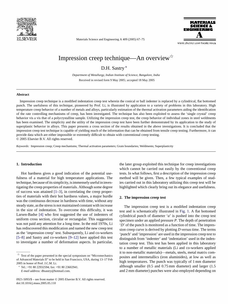
The impression creep test is a modified indentation ctest and is schematically illustrated inFig. 1. A flat bottomedcylindrical punch of diameter ‘a’ is pushed into the creep tespecimen under an applied pressureP. The depth of penetratio‘D’ of the punch is monitored as a function of time. The impsion creep curve is derived by plottingD versus time. The term‘punch’ and ‘impression’ are used in the impression creep tedistinguish from ‘indenter’ and ‘indentation’ used in the indtation creep test. This test has been applied in this laborto a number of metallic materials (Li and co-workers appit to non-metallic materials)—metals, steels, metal matrix cposites and intermetallics (iron aluminides), at low as we
f Advanced Materials II” to be held in San Francisco, USA, during 13–17 Feb005 in honor of Prof. J.C.M. Li.∗ Tel.: +91 80 22932594; fax: +91 80 23602941.
E-mail address:[email protected].
high temperatures. The punch was typically of 1 mm diameteralthough smaller (0.5 and 0.75 mm diameter) and larger (1.5and 2 mm diameter) punches were also employed depending on
921-5093/$ – see front matter © 2005 Elsevier B.V. All rights reserved.oi:10.1016/j.msea.2005.05.110
68 D.H. Sastry / Materials Science and Engineering A 409 (2005) 67–75
Fig. 1. Schematic of the impression creep test.
the application. They were made of stainless steel for studyingmaterials such as cadmium, zinc while tungsten carbide and alu-mina punches were used for creep tests at temperatures aboveabout 650 K. Some testing was done in vacuum, especially whentungsten carbide punches at temperatures above 700 K wereemployed. An LVDT-amplifier assembly was used to monitorthe punch penetration depth.
The impression creep data were compared with thoseobtained with conventional tensile creep testing and/or constanrate tensile testing in order to validate the impression creep tesand also to establish the relationship between the two types ocreep parameters. Metallographic investigations were carrieout to investigate the depth of plastic zone under the punch suface.
It was clear from an extensive analysis of the data that theimpression creep test is an elegant test technique which offerthe following advantages over the conventional creep testing:
1. A small quantity of testing material is sufficient whichprovides an inexpensive method of developing new andadvanced materials.
2. Constant stress can be obtained with a constant load.3. The temperature and stress dependence of the steady state
minimum) creep rate can be obtained on a single specimenthereby making more valid the assumption of constancy of
ationact
4 ationves
5 medif-pless inundstic
A cross section of the results obtained in some of the inves-tigations carried out will now be presented.
3. Creep mechanisms in HCP metals at hightemperatures
Impression creep tests were carried out on HCP metals –cadmium, zinc and magnesium – at temperatures higher than0.4 on the homologous temperature scale. On the same materialsconventional tensile creep testing was also carried out in orderto examine the interrelationship between the two. The resultsobtained on all the three metals are similar (for example, seeRef.[11]), and therefore, results of a type will be presented onlyon one metal and the results and conclusions drawn apply to theothers as well.
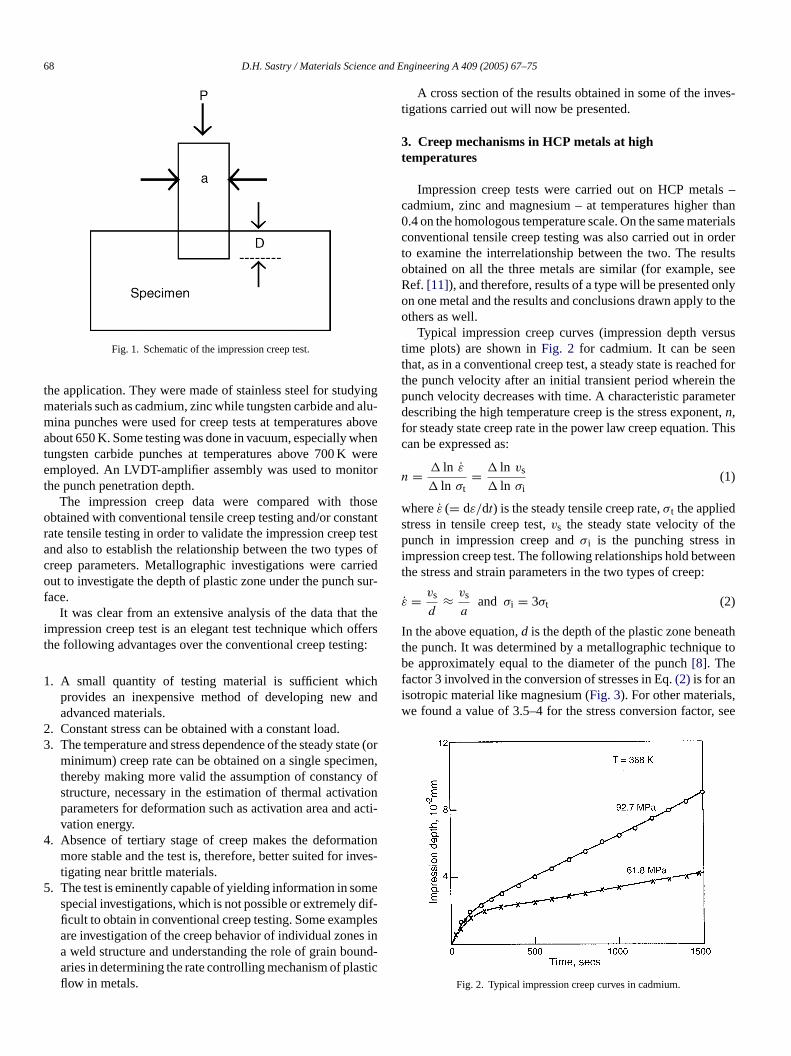
Typical impression creep curves (impression depth versustime plots) are shown inFig. 2 for cadmium. It can be seenthat, as in a conventional creep test, a steady state is reached forthe punch velocity after an initial transient period wherein thepunch velocity decreases with time. A characteristic parameterdescribing the high temperature creep is the stress exponent,n,for steady state creep rate in the power law creep equation. Thiscan be expressed as:
n = � ln ε
� ln σt= � ln vs
� ln σi(1)
ws hep ini eent
ε
I atht ue tobfi ,w , see
structure, necessary in the estimation of thermal activparameters for deformation such as activation area andvation energy.
. Absence of tertiary stage of creep makes the deformmore stable and the test is, therefore, better suited for itigating near brittle materials.
. The test is eminently capable of yielding information in sospecial investigations, which is not possible or extremelyficult to obtain in conventional creep testing. Some examare investigation of the creep behavior of individual zonea weld structure and understanding the role of grain boaries in determining the rate controlling mechanism of plaflow in metals.
ttf
dr-
s
(or,
i-
n-
-
hereε (= dε/dt) is the steady tensile creep rate,σt the appliedtress in tensile creep test,vs the steady state velocity of tunch in impression creep andσ i is the punching stress
mpression creep test. The following relationships hold betwhe stress and strain parameters in the two types of creep:
˙ = vs
d≈ vs
aand σi = 3σt (2)
n the above equation,d is the depth of the plastic zone benehe punch. It was determined by a metallographic techniqe approximately equal to the diameter of the punch[8]. The
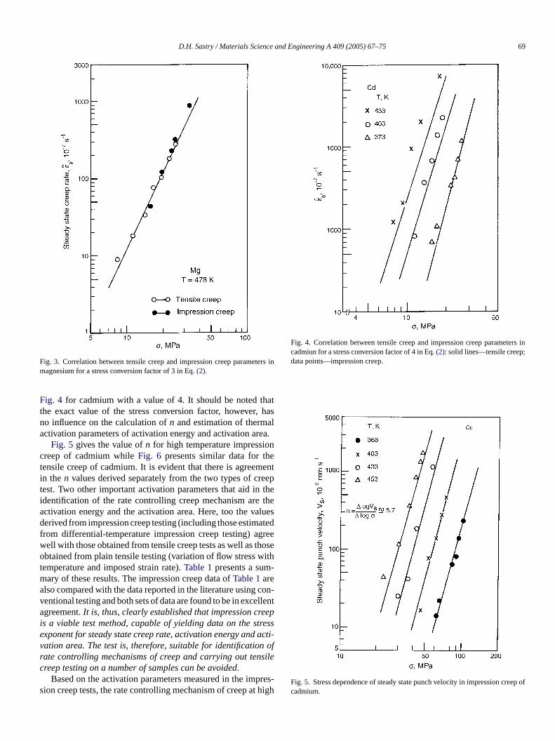
actor 3 involved in the conversion of stresses in Eq.(2) is for ansotropic material like magnesium (Fig. 3). For other materialse found a value of 3.5–4 for the stress conversion factor
Fig. 2. Typical impression creep curves in cadmium.
D.H. Sastry / Materials Science and Engineering A 409 (2005) 67–75 69
Fig. 3. Correlation between tensile creep and impression creep parameters inmagnesium for a stress conversion factor of 3 in Eq.(2).
Fig. 4 for cadmium with a value of 4. It should be noted thatthe exact value of the stress conversion factor, however, hasno influence on the calculation ofn and estimation of thermalactivation parameters of activation energy and activation area.
Fig. 5 gives the value ofn for high temperature impressioncreep of cadmium whileFig. 6 presents similar data for thetensile creep of cadmium. It is evident that there is agreementin the n values derived separately from the two types of creeptest. Two other important activation parameters that aid in theidentification of the rate controlling creep mechanism are theactivation energy and the activation area. Here, too the valuesderived from impression creep testing (including those estimatedfrom differential-temperature impression creep testing) agreewell with those obtained from tensile creep tests as well as thoseobtained from plain tensile testing (variation of flow stress withtemperature and imposed strain rate).Table 1presents a sum-mary of these results. The impression creep data ofTable 1arealso compared with the data reported in the literature using con-ventional testing and both sets of data are found to be in excellentagreement.It is, thus, clearly established that impression creepis a viable test method, capable of yielding data on the stressexponent for steady state creep rate, activation energy and acti-vation area. The test is, therefore, suitable for identification ofrate controlling mechanisms of creep and carrying out tensilecreep testing on a number of samples can be avoided.
Based on the activation parameters measured in the impres-s t high
Fig. 4. Correlation between tensile creep and impression creep parameters incadmiun for a stress conversion factor of 4 in Eq.(2): solid lines—tensile creep;data points—impression creep.
Fig. 5. Stress dependence of steady state punch velocity in impression creep ofcadmium.
ion creep tests, the rate controlling mechanism of creep a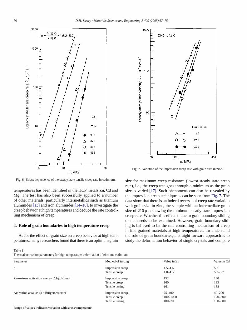
70 D.H. Sastry / Materials Science and Engineering A 409 (2005) 67–75
Fig. 6. Stress dependence of the steady state tensile creep rate in cadmium.
temperatures has been identified in the HCP metals Zn, Cd andMg. The test has also been successfully applied to a numberof other materials, particularly intermetallics such as titaniumaluminides[13] and iron aluminides[14–16], to investigate thecreep behavior at high temperatures and deduce the rate control-ling mechanism of creep.
4. Role of grain boundaries in high temperature creep
As for the effect of grain size on creep behavior at high tem-peratures, many researchers found that there is an optimum grain
Fig. 7. Variation of the impression creep rate with grain size in zinc.
size for maximum creep resistance (lowest steady state creeprate), i.e., the creep rate goes through a minimum as the grainsize is varied[17]. Such phenomena can also be revealed bythe impression creep technique as can be seen fromFig. 7. Thedata show that there is an indeed reversal of creep rate variationwith grain size in zinc, the sample with an intermediate grainsize of 210�m showing the minimum steady state impressioncreep rate. Whether this effect is due to grain boundary slidingor not needs to be examined. However, grain boundary slid-ing is believed to be the rate controlling mechanism of creepin fine grained materials at high temperatures. To understandthe role of grain boundaries, a straight forward approach is tostudy the deformation behavior of single crystals and compare
Table 1Thermal activation parameters for high temperature deformation of zinc and cadmium
Parameter Method of testing Value in Zn Value in Cd
n Impression creep 4.5–4.6 5.7Tensile creep 4.0–4.5 5.2–5.7
Zero-stress activation energy,�H0, kJ/mol Impression creep 152 130Tensile creep 160 123Tensile testing 161 138
Activation area,b2 (b= Burgers vector) Impression creep 75–400 40–200Tensile creep 100–1000 120–600Tensile testing 100–700 100–600
Range of values indicates variation with stress/temperature.
D.H. Sastry / Materials Science and Engineering A 409 (2005) 67–75 71
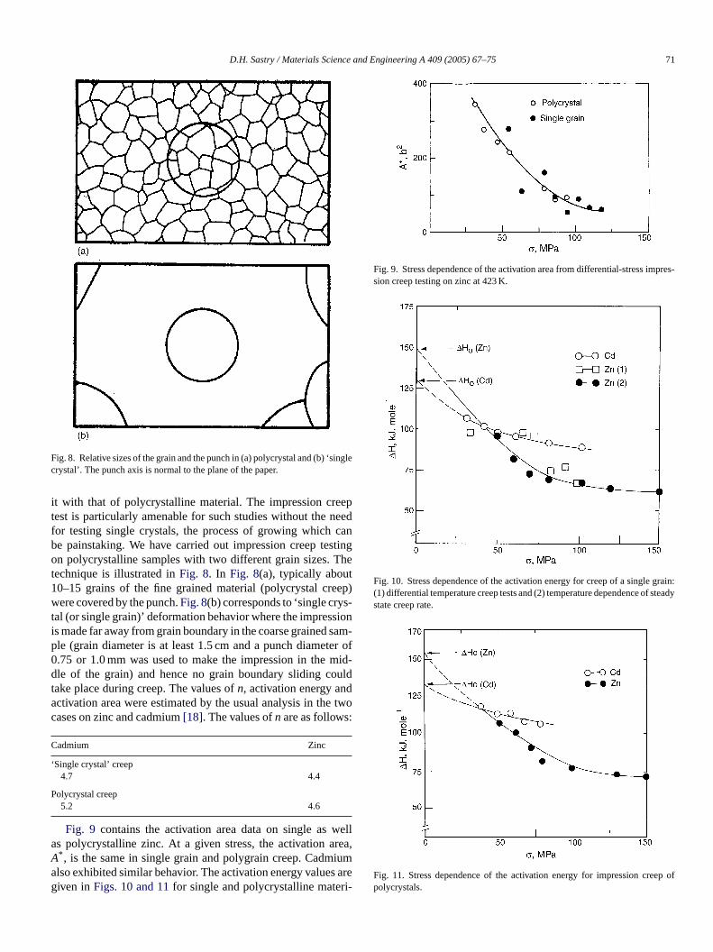
Fig. 8. Relative sizes of the grain and the punch in (a) polycrystal and (b) ‘singlecrystal’. The punch axis is normal to the plane of the paper.
it with that of polycrystalline material. The impression creeptest is particularly amenable for such studies without the needfor testing single crystals, the process of growing which canbe painstaking. We have carried out impression creep testingon polycrystalline samples with two different grain sizes. Thetechnique is illustrated inFig. 8. In Fig. 8(a), typically about10–15 grains of the fine grained material (polycrystal creep)were covered by the punch.Fig. 8(b) corresponds to ‘single crys-tal (or single grain)’ deformation behavior where the impressionis made far away from grain boundary in the coarse grained sam-ple (grain diameter is at least 1.5 cm and a punch diameter of0.75 or 1.0 mm was used to make the impression in the mid-dle of the grain) and hence no grain boundary sliding couldtake place during creep. The values ofn, activation energy andactivation area were estimated by the usual analysis in the twocases on zinc and cadmium[18]. The values ofn are as follows:
Cadmium Zinc
‘Single crystal’ creep4.7 4.4
Polycrystal creep5.2 4.6
Fig. 9 contains the activation area data on single as wellas polycrystalline zinc. At a given stress, the activation area,A* , is the same in single grain and polygrain creep. Cadmiuma s areg ri-
Fig. 9. Stress dependence of the activation area from differential-stress impres-sion creep testing on zinc at 423 K.
Fig. 10. Stress dependence of the activation energy for creep of a single grain:(1) differential temperature creep tests and (2) temperature dependence of steadystate creep rate.
Fig. 11. Stress dependence of the activation energy for impression creep ofpolycrystals.
lso exhibited similar behavior. The activation energy valueiven inFigs. 10 and 11for single and polycrystalline mate
72 D.H. Sastry / Materials Science and Engineering A 409 (2005) 67–75
als of the two metals, respectively. The equivalence of all thecreep parameters (including�H0, the zero-stress creep activa-tion energy) in the single- and ploy-crystal cases shows that creepoccurs in both by the same mechanism. Since grain boundarysliding is absent in the single grain case (choice of relative sizesof the grain and punch as well as the impression being made faraway from a grain boundary ensure this), it follows that creepin these HCP metals, under the conditions of stress and tem-perature employed, is not controlled by grain boundary sliding.It is probably controlled by a mechanism such as breaking ofattractive junctions or by climb of edge dislocations. However,what is significant here is the revelation that the impression creepmethod provides an unique and elegant way of investigating thegrain size effects in creep. The test can likewise be adopted toexamine the creep behavior of 2-phase materials (by making theimpressions separately in each phase and making the impressionto cover both phases) which is not well understood. These possi-bilities are bound to enhance the utility of this creep technique.
5. Creep of weldments
Weldments are often highly heterogeneous since themicrostructure as well as the chemical composition couldvary with position. The microstructural/compositional gradientsimpart different properties to the different zones namely the base
material, the heat affected zone (HAZ), the fusion zone and theweld proper. The complexity is even greater in multiple passwelds since each pass could yield a different microstructure. Theconventional testing methods yield either an average property orthe property of the weakest zone depending on the test samplegeometry employed. By contrast, the impression technique canbe profitably employed for the measurement of spatial variationsin the creep properties of weldments[19,20]. As an example,investigations carried out on AISI type 316 steel weldmentsand a modified T91 steel (9% Cr, 1% Mo and small quantitiesof Nb, V, Mn, etc.) weldments will be described. Impressioncreep specimens were prepared by slicing the weldment in dif-ferent directions so that impression could be made in the desiredregion—HAZ or weld or base material. Microstructural observa-tions and measurement of the�-ferrite in 316 steel were carriedout by standard methods.
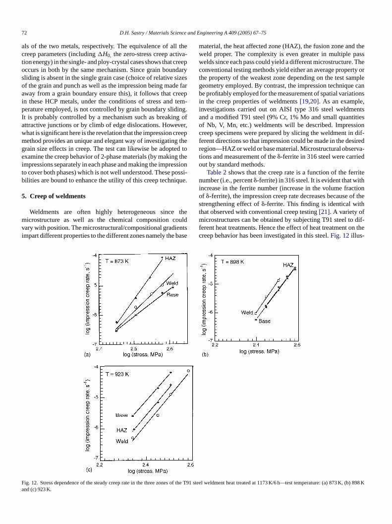
Table 2shows that the creep rate is a function of the ferritenumber (i.e., percent�-ferrite) in 316 steel. It is evident that withincrease in the ferrite number (increase in the volume fractionof �-ferrite), the impression creep rate decreases because of thestrengthening effect of�-ferrite. This finding is identical withthat observed with conventional creep testing[21]. A variety ofmicrostructures can be obtained by subjecting T91 steel to dif-ferent heat treatments. Hence the effect of heat treatment on thecreep behavior has been investigated in this steel.Fig. 12illus-
Fa
ig. 12. Stress dependence of the steady creep rate in the three zones of thend (c) 923 K.
T91 steel weldment heat treated at 1173 K/6 h—test temperature: (a) 873 K, (b) 898 K
D.H. Sastry / Materials Science and Engineering A 409 (2005) 67–75 73
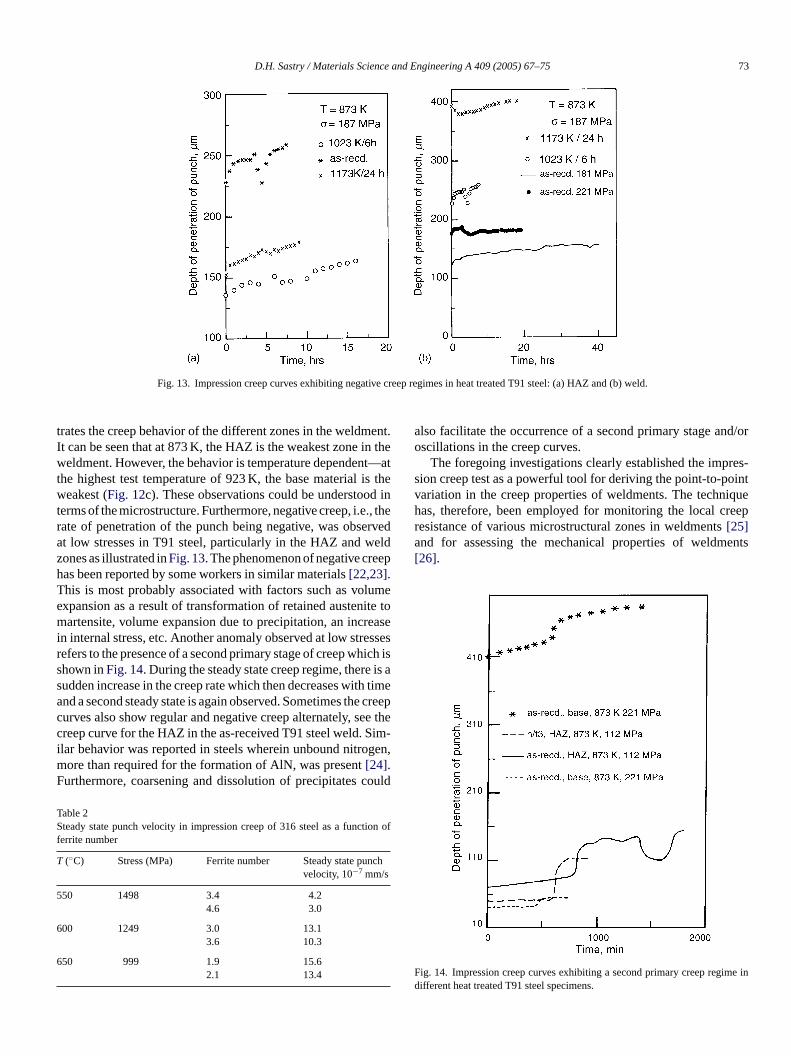
Fig. 13. Impression creep curves exhibiting negative creep regimes in heat treated T91 steel: (a) HAZ and (b) weld.
trates the creep behavior of the different zones in the weldment.It can be seen that at 873 K, the HAZ is the weakest zone in theweldment. However, the behavior is temperature dependent—atthe highest test temperature of 923 K, the base material is theweakest (Fig. 12c). These observations could be understood interms of the microstructure. Furthermore, negative creep, i.e., therate of penetration of the punch being negative, was observedat low stresses in T91 steel, particularly in the HAZ and weldzones as illustrated inFig. 13. The phenomenon of negative creephas been reported by some workers in similar materials[22,23].This is most probably associated with factors such as volumeexpansion as a result of transformation of retained austenite tomartensite, volume expansion due to precipitation, an increasein internal stress, etc. Another anomaly observed at low stressesrefers to the presence of a second primary stage of creep which isshown inFig. 14. During the steady state creep regime, there is asudden increase in the creep rate which then decreases with timeand a second steady state is again observed. Sometimes the creepcurves also show regular and negative creep alternately, see thecreep curve for the HAZ in the as-received T91 steel weld. Sim-ilar behavior was reported in steels wherein unbound nitrogen,more than required for the formation of AlN, was present[24].Furthermore, coarsening and dissolution of precipitates could
Table 2Steady state punch velocity in impression creep of 316 steel as a function off
T ch
5
6
6
also facilitate the occurrence of a second primary stage and/oroscillations in the creep curves.
The foregoing investigations clearly established the impres-sion creep test as a powerful tool for deriving the point-to-pointvariation in the creep properties of weldments. The techniquehas, therefore, been employed for monitoring the local creepresistance of various microstructural zones in weldments[25]and for assessing the mechanical properties of weldments[26].
F ime indifferent heat treated T91 steel specimens.
errite number
(◦C) Stress (MPa) Ferrite number Steady state punvelocity, 10−7 mm/s
50 1498 3.4 4.24.6 3.0
00 1249 3.0 13.13.6 10.3
50 999 1.9 15.62.1 13.4
ig. 14. Impression creep curves exhibiting a second primary creep reg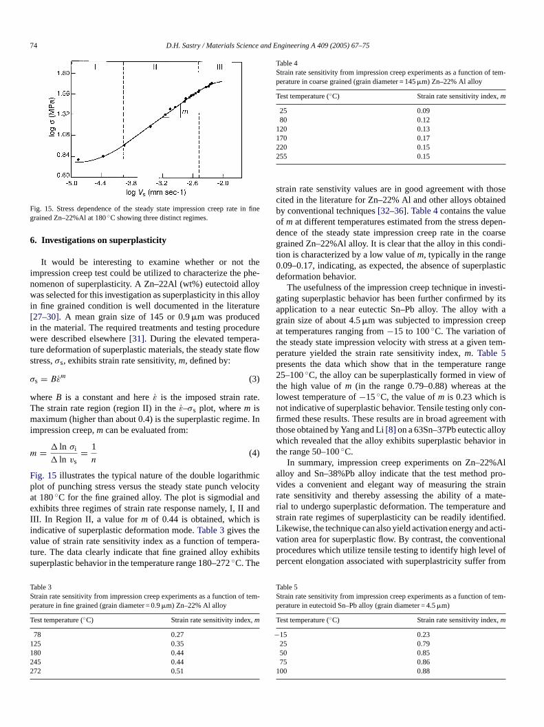
74 D.H. Sastry / Materials Science and Engineering A 409 (2005) 67–75
Fig. 15. Stress dependence of the steady state impression creep rate in finegrained Zn–22%Al at 180◦C showing three distinct regimes.
6. Investigations on superplasticity
It would be interesting to examine whether or not theimpression creep test could be utilized to characterize the phe-nomenon of superplasticity. A Zn–22Al (wt%) eutectoid alloywas selected for this investigation as superplasticity in this alloyin fine grained condition is well documented in the literature[27–30]. A mean grain size of 145 or 0.9�m was producedin the material. The required treatments and testing procedurewere described elsewhere[31]. During the elevated tempera-ture deformation of superplastic materials, the steady state flowstress,σs, exhibits strain rate sensitivity,m, defined by:
σs = Bεm (3)
whereB is a constant and hereε is the imposed strain rate.The strain rate region (region II) in theε–σs plot, wherem ismaximum (higher than about 0.4) is the superplastic regime. Inimpression creep,m can be evaluated from:
m = � ln σi
� ln vs= 1
n(4)
Fig. 15 illustrates the typical nature of the double logarithmicplot of punching stress versus the steady state punch velocitat 180◦C for the fine grained alloy. The plot is sigmodial andexhibits three regimes of strain rate response namely, I, II andI isiv era-t ibitss
TS f temp
T
1122
Table 4Strain rate sensitivity from impression creep experiments as a function of tem-perature in coarse grained (grain diameter = 145�m) Zn–22% Al alloy
Test temperature (◦C) Strain rate sensitivity index,m
25 0.0980 0.12
120 0.13170 0.17220 0.15255 0.15
strain rate senstivity values are in good agreement with thosecited in the literature for Zn–22% Al and other alloys obtainedby conventional techniques[32–36]. Table 4contains the valueof m at different temperatures estimated from the stress depen-dence of the steady state impression creep rate in the coarsegrained Zn–22%Al alloy. It is clear that the alloy in this condi-tion is characterized by a low value ofm, typically in the range0.09–0.17, indicating, as expected, the absence of superplasticdeformation behavior.
The usefulness of the impression creep technique in investi-gating superplastic behavior has been further confirmed by itsapplication to a near eutectic Sn–Pb alloy. The alloy with agrain size of about 4.5�m was subjected to impression creepat temperatures ranging from−15 to 100◦C. The variation ofthe steady state impression velocity with stress at a given tem-perature yielded the strain rate sensitivity index,m. Table 5presents the data which show that in the temperature range25–100◦C, the alloy can be superplastically formed in view ofthe high value ofm (in the range 0.79–0.88) whereas at thelowest temperature of−15◦C, the value ofm is 0.23 which isnot indicative of superplastic behavior. Tensile testing only con-firmed these results. These results are in broad agreement withthose obtained by Yang and Li[8] on a 63Sn–37Pb eutectic alloywhich revealed that the alloy exhibits superplastic behavior inthe range 50–100◦C.
In summary, impression creep experiments on Zn–22%Ala pro-v trainr ate-r ands ified.L acti-v ionalp l ofp from
TS f tem-p
T
−
1
II. In Region II, a value form of 0.44 is obtained, whichndicative of superplastic deformation mode.Table 3gives thealue of strain rate sensitivity index as a function of tempure. The data clearly indicate that fine grained alloy exhuperplastic behavior in the temperature range 180–272◦C. The
able 3train rate sensitivity from impression creep experiments as a function oerature in fine grained (grain diameter = 0.9�m) Zn–22% Al alloy
est temperature (◦C) Strain rate sensitivity index,m
78 0.2725 0.3580 0.4445 0.4472 0.51
y
-
lloy and Sn–38%Pb alloy indicate that the test methodides a convenient and elegant way of measuring the sate sensitivity and thereby assessing the ability of a mial to undergo superplastic deformation. The temperaturetrain rate regimes of superplasticity can be readily identikewise, the technique can also yield activation energy andation area for superplastic flow. By contrast, the conventrocedures which utilize tensile testing to identify high leveercent elongation associated with superplastricity suffer
able 5train rate sensitivity from impression creep experiments as a function oerature in eutectoid Sn–Pb alloy (grain diameter = 4.5�m)
est temperature (◦C) Strain rate sensitivity index,m
15 0.2325 0.7950 0.8575 0.8600 0.88
D.H. Sastry / Materials Science and Engineering A 409 (2005) 67–75 75
the problems of change in strain rate with strain (resulting fromlarge elongation) and maintaining the temperature constant overthe large gauge length of the specimen. Furthermore, impres-sion creep testing, unlike unidirectional tensile testing, reflectsmore closely the deformation mode operative during superplas-tic forming.
7. Conclusions
The impression creep test is not only viable but also a versa-tile test method. It offers several advantages over conventionalcreep testing such as small quantity of testing material, tem-perature and stress dependence of creep rate obtainable on asingle specimen (thereby making more valid the assumption ofconstant structure), constant stress at a constant load, absenceof tertiary stage (making it suitable for not so ductile materi-als), etc. This technique has been validated by comparing thedata obtained on the same material under identical conditionsfrom tensile as well as impression creep testing. In this lab-oratory, the impression creep technique has been extensivelyused in several investigations such as identification of the ratecontrolling creep mechanisms, effect of grain boundaries, posi-tion dependent creep properties of weldments, superplastic flowcharacteristics of alloys, creep behavior of new materials, etc.A cross section of the results obtained are presented here. Theresults demonstrate that the impression creep test technique isc inedf dataw ithc
A
adeb re dut parm hea rtialfi
R
.
[3] H.D. Merchant, G.S. Murty, S.N. Bahadur, L.T. Dwivedi, Y. Mehrotra,J. Mater. Sci. 8 (1973) 437–442.
[4] J. Larsen-Badse, ORNL-TM-1862 Report, 1967; also paper presented atthe Annual Meeting of AIME, Los Angeles.
[5] S.N.G. Chu, J.C.M. Li, J. Mater. Sci. 12 (1977) 2200–2208.[6] E.C. Yu, J.C.M. Li, Phil. Mag. 36 (1977) 811–825.[7] H.Y. Yu, J.C.M. Li, J. Mater. Sci. 12 (1977) 2214–2222.[8] F. Yang, J.C.M. Li, Mat. Sci. Eng. A201 (1995) 50–57.[9] G.S. Murthy, Ph.D. Thesis, Indian Institute of Science, Bangalore,
1981.[10] G.S. Murthy, D.H. Sastry, Trans. Ind. Inst. Met. 34 (1981) 195–201.[11] G.S. Murthy, D.H. Sastry, Phy. Stat. Sol. 70 (1982) 63–71.[12] D.H. Sastry, G.S. Murthy, in: H.J. McQueen, J.-P. Bailon, J.I. Dickson,
J.J. Jonas, M.G. Akben (Eds.), Proceedings of Seventh Internatinal Con-ference on the Strength of Metals and Alloys, Montreal, Canada, 1985,p. 625.
[13] R.S. Sundar, D.H. sastry, Trans. I.I.M. 49 (1996) 437–441.[14] R.S. Sundar, T.R.G. Kutty, D.H. Sastry, Intermetallics 8 (2000) 427–
437.[15] R.S. Sundar, D.H. Sastry, Intermetallics 8 (2000) 1061–1065.[16] M. Sujata, D.H. Sastry, C. Ramachandra, Intermetallics 12 (2004)
691–697.[17] D.K. Matlock, W.D. Nix, Met. Trans. 5 (1974) 961–963.[18] G.S. Murthy, D.H. Sastry, TMS Lett. 5 (2004) 105–106.[19] J.N. Buzruk, D.H. Sastry, Indian Institute of Science, Bangalore, unpub-
lished work.[20] K. Kapila, K.S. Raman, D.H. Sastry, Indian Institute of Science, Ban-
galore, unpublished work.[21] W.T. DeLong, Welding J. 53 (1974) 273-s.[22] R.L. Klueh, Mat. Sci. Eng. 35 (1978) 239–253.[23] J.P. Milan, Proceedings of Fourth Intra American Conference on Mate-
[[ (6)
[[ 7)
[ 285–
[ 88)
[[ 90)
[ 77)
[[[ 8)
[
apable of yielding much of the information that can be obtarom tensile creep testing, and furthermore, can providehich are either impossible or extremely difficult to obtain wonventional creep testing.
cknowledgements
The author gratefully acknowledges the contributions my his graduate students in these investigations. Thanks a
o the Department of Science and Technology and the Deent of Atomic Energy for partially financing the work. Tuthor is grateful to US Army Asian Research Office for panancial support to attend the symposium.
eferences
[1] E.R. Petty, Metallurgia 65 (1962) 25–26.[2] A.G. Atkins, A. Silverio, D. Tabor, J. Inst. Met. 94 (1966) 369–378
et-
rials Technology, Caracas, 1975, p. 102.24] M. Schirra, K. Anderko, Steel Res. (Mater. Technol.) 6 (1990).25] W.S. Gibbs, S.H. Wang, D.K. Matlock, D.C. Olson, Welding J. 64
(1985) 153s–158s.26] H.Y. Yu, M.A. Imam, B.B. Rath, Welding J. 64 (2) (1985) 55-s.27] I.I. Novikov, V.K. Portnoy, T.E. Terentieva, Acta Metall. 25 (197
1139–1149.28] P. Shariat, R.B. Vastava, T.G. Langdon, Acta Metall. 30 (1982)
296.29] Z.R. Lin, A.H. Chokshi, T.G. Langdon, J. Mater. Sci. 23 (19
2712–2722.30] F. Yang, J.C.M. Li, Mat. Sci. Eng. A201 (1995) 40–49.31] N. Kumar, K.S. Raman, D.H. Sastry, E.A. Little, J. Mater. Sci. 25 (19
753.32] H. Ishikawa, F.A. Mohamed, T.G. Langdon, Met. Trans. 8A (19
9331.33] D.A. Holt, Trans. Metall. Soc. AIME 242 (1968) 25.34] A. Ball, M.M. Hutchinson, Met. Sci. J. 3 (1969) 1.35] O.A. Kaibyshev, B.V. Radinov, R.Z. Valiev, Acta Metall. 26 (197
1877–1886.36] D.W. Liversey, N. Ridley, Scripta Metall. 1 (1982) 165–168.