improved dp-capability with tilted thrusters and smart...
TRANSCRIPT

DYNAMIC POSITIONING CONFERENCE October 11-12, 2016
THRUSTERS
Nobert BultenPetra Stoltenkamp
Wärtsilä Propulsion Technology
Improved DP-Capability with Tilted Thrusters and Smart Controls Algorithims

© Wärtsilä PUBLIC
Improved DP-capability with tilted thrusters and smart controls algorithmsNorbert BultenGeneral Manager HydrodynamicsWärtsilä Propulsion - Technology
11.10.2016 Improved DP-capability with tilted thrusters / N. Bulten1

© Wärtsilä PUBLIC 11.10.2016 Improved DP-capability with tilted thrusters / N. Bulten2
Contents
• Introduction• System integration on DP-capability
• Thruster bollard pull performance• Impact of tilt configurations• Impact on hull-interaction losses
• Thrust allocation / controls algorithms• Corridor approach• Load balancing
• Conclusions
Animation: Courtesy of mr Albert Drost

© Wärtsilä PUBLIC 11.10.2016 Improved DP-capability with tilted thrusters / N. Bulten3
System integration: impact on DP-capability and fuel consumption
Controls Power generation Drive-line Propeller
Ther
mal
/ ch
emic
alef
ficie
ncy
Ther
mal
/ ch
emic
alef
ficie
ncy
Mec
hani
cal
effic
ienc
yM
echa
nica
l ef
ficie
ncy
Hyd
rody
nam
ic
effic
ienc
yH
ydro
dyna
mic
ef
ficie
ncy
Smar
t C
ontr
ols
Smar
t C
ontr
ols
DP-capability & fuel consumptionDP-capability & fuel consumption

© Wärtsilä PUBLIC 11.10.2016 Improved DP-capability with tilted thrusters / N. Bulten4
Steerable thrusters for Dynamic Positioning
• Overall efficiency of the dynamic positioning system depends on: • Hydrodynamic efficiency of steerable thrusters• Thruster interaction losses with hull and other thruster units• Smart controls systems to set the right steering angle and
power to each thruster on the vessel

© Wärtsilä PUBLIC
Thruster unit bollard pull
Hull interaction
lossesForbidden
zones
Load balancing
Steering angle adjustment
Load balancing
11.10.2016 Improved DP-capability with tilted thrusters / N. Bulten5
DP thrust calculation steps
1
2
3
5
64
• The following steps can be identified in the DP-thrust allocation process
© Wärtsilä PUBLIC
THRUSTER BOLLARD PULL PERFORMANCE
11.10.2016 Improved DP-capability with tilted thrusters / N. Bulten6

© Wärtsilä PUBLIC 11.10.2016 Improved DP-capability with tilted thrusters / N. Bulten7
Thruster DP-performance evaluation
• A detailed hydrodynamic analysis of the Dynamic Positioning capabilities of two steerable thruster types has been made.
• The following thruster types have been reviewed:
• The analysis focusses on:• 1) Open water performance • 2) DP-capability for a drill ship (3 units in the bow and 3 in the stern)
Type Power [kW] Diameter [mm] Tilt concept Tilt angleWST-55U 5500 3900 Shaft 8Reference unit 5500 4100 Nozzle 5
Thruster unit bollard pull
Hull interaction
lossesForbidden
zones
Load balancing
Steering angle adjustment
Load balancing
© Wärtsilä PUBLIC 11.10.2016 Improved DP-capability with tilted thrusters / N. Bulten8
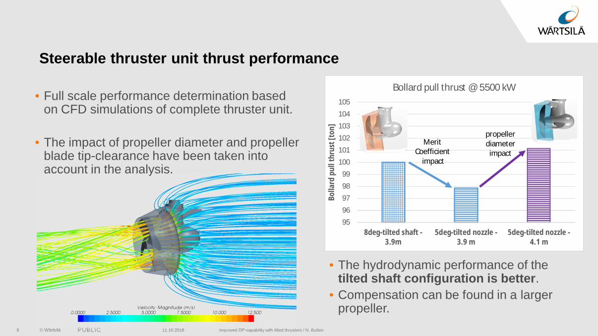
Steerable thruster unit thrust performance
• Full scale performance determination based on CFD simulations of complete thruster unit.
• The impact of propeller diameter and propeller blade tip-clearance have been taken into account in the analysis.
95
96
97
98
99
100
101
102
103
104
105
8deg-tilted shaft -3.9m
5deg-tilted nozzle -3.9 m
5deg-tilted nozzle -4.1 m
Bolla
rd p
ull t
hrus
t [to
n]
Bollard pull thrust @ 5500 kW
Merit Coefficient
impact
propellerdiameter
impact
• The hydrodynamic performance of the tilted shaft configuration is better.
• Compensation can be found in a larger propeller.

© Wärtsilä PUBLIC 11.10.2016 Improved DP-capability with tilted thrusters / N. Bulten9
Steerable thruster hull-interaction
• For a proper numerical simulation of the wake of a thruster a transient CFD simulation is required.
• The 8 tilted shaft unit can be analyzed with Moving Mesh or Overlapping Grids.
• In case of misalignment between propeller and nozzle the Overlapping Grid option is the only option.
• The industry reference unit with 5 tilted nozzle can now be analyzed in proper way with the available Overlapping Gridmethod.
Thruster unit bollard pull
Hull interaction
lossesForbidden
zones
Load balancing
Steering angle adjustment
Load balancing

© Wärtsilä PUBLIC 11.10.2016 Improved DP-capability with tilted thrusters / N. Bulten10
Steerable thruster hull-interaction
• Thruster-hull interaction has been determined for the 8tilted shaft unit and for the 5 tilted nozzle reference unit.
• Significant differences in wake deflection can be seen.
• Once the wake hits the hull, the hull-interaction losses will increase significantly.
• Only for the 8 tilted unit the deflection is sufficient to avoid these interaction losses.
8 tilted unit
5 tilted nozzleConfiguration Average wake deflection
Minimum wake deflection
8 - tilted shaft -5 -15 - tilted nozzle -2 +20 - conventional 0 +4

© Wärtsilä PUBLIC
Thruster-thruster interaction
• The thrust losses of the interaction with a second steerable thruster have been determined with aid of numerical flow simulations (CFD).
• A CFD model has been made with two thruster units. The steering angle of the upstream unit and the distance has been varied to determine the overall performance.
11.10.2016 Improved DP-capability with tilted thrusters / N. Bulten11
X=7 D
• The total thrust of two units has been determined for each condition.
• Based on this analysis the optimum steering angle has been determined.
Thruster unit bollard pull
Hull interaction
lossesForbidden
zones
Load balancing
Steering angle adjustment
Load balancing

© Wärtsilä PUBLIC 11.10.2016 Improved DP-capability with tilted thrusters / N. Bulten12
Thruster-thruster interaction: effect of steering
• The jets out of the upstream thruster depends on the steering angle.• Results for two steering angles of the upstream thruster unit are shown below for the
thruster with 8 tilted shaft.
= 0 degrees
Wake upstream thruster partly blown below downstream thruster
= 13.5 degrees
no interaction

© Wärtsilä PUBLIC
Optimum Thrust Angle determination
11.10.2016 Improved DP-capability with tilted thrusters / N. Bulten13
Losses due to thruster-thruster interaction
Losses due to steering angle of upstream thruster
Optimum thrust is the angle at which the losses due to turning the upstream thruster together with the losses due to thruster-thruster interaction are minimized.
cos0TTTT downstrupstrtotal
x
D
The zone within the optimum angle is denoted as forbidden zone, due to thruster-thruster interaction.

© Wärtsilä PUBLIC
CORRIDOR APPROACH
11.10.2016 Improved DP-capability with tilted thrusters / N. Bulten14

© Wärtsilä PUBLIC
Drill ship – thruster-thruster-thruster interaction
• The interaction between the three units in the stern of a drill ship can lead to an interesting phenomenon.
• Depending on the location of the thruster units, the two forbidden zones can overlap.
• This results in one single large forbidden zone for the steerable thruster.
11.10.2016 Improved DP-capability with tilted thrusters / N. Bulten15

© Wärtsilä PUBLIC
Polar plot of thruster performance
• The available thrust of the unit is shown for the complete 360 circumference.
• The interaction losses with the hull and due to the forbidden zones are taken into account.
• At approx. 70 about 60% thrust is available in this configuration.
• Note: this analysis has been made for a conventional, straight thruster unit.
11.10.2016 Improved DP-capability with tilted thrusters / N. Bulten16
010
2030
40
50
60
70
80
90
100
110
120
130
140
150160
170180
190200
210
220
230
240
250
260
270
280
290
300
310
320
330340
350
Stern thruster performance of starboard unit
0%
20%
40%
60%
80%
100%
© Wärtsilä PUBLIC
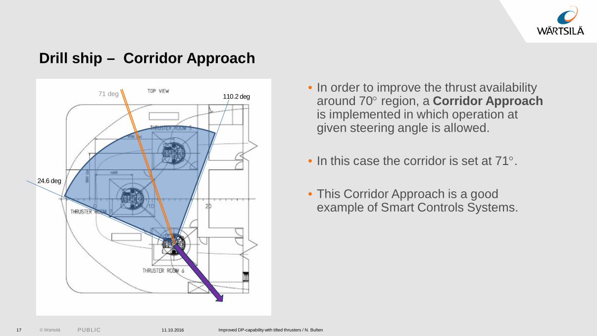
Drill ship – Corridor Approach
• In order to improve the thrust availability around 70 region, a Corridor Approach is implemented in which operation at given steering angle is allowed.
• In this case the corridor is set at 71 .
• This Corridor Approach is a good example of Smart Controls Systems.
11.10.2016 Improved DP-capability with tilted thrusters / N. Bulten17
110.2 deg
24.6 deg
71 deg
© Wärtsilä PUBLIC 11.10.2016 Improved DP-capability with tilted thrusters / N. Bulten18
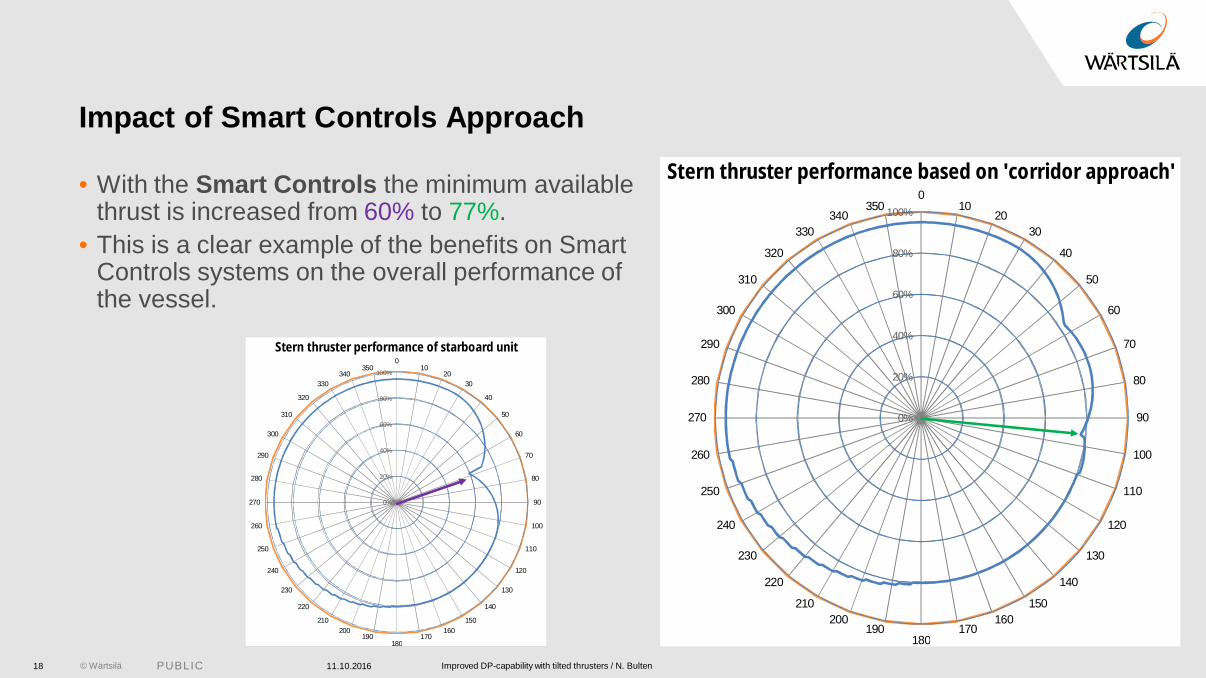
Impact of Smart Controls Approach
• With the Smart Controls the minimum available thrust is increased from 60% to 77%.
• This is a clear example of the benefits on Smart Controls systems on the overall performance of the vessel.
010
2030
40
50
60
70
80
90
100
110
120
130
140
150160
170180
190200
210
220
230
240
250
260
270
280
290
300
310
320
330340
350
Stern thruster performance of starboard unit
0%
20%
40%
60%
80%
100%
010
2030
40
50
60
70
80
90
100
110
120
130
140
150160
170180
190200
210
220
230
240
250
260
270
280
290
300
310
320
330340
350
Stern thruster performance based on 'corridor approach'
0%
20%
40%
60%
80%
100%

© Wärtsilä PUBLIC
THRUST ALLOCATION ON DRILL SHIP
11.10.2016 Improved DP-capability with tilted thrusters / N. Bulten19

© Wärtsilä PUBLIC 11.10.2016 Improved DP-capability with tilted thrusters / N. Bulten20
Drill ship performance
• The overall DP-capability of a drill ship is based on the performance of the 6 thrusters together.
• In order to eliminate the yaw moment around the vessel center-point, the input loads of all thrusters have to be balanced. This can be achieved by:• Balancing of the magnitude of the thrust factor (load balancing)• Adjustment of steering angles to modify the torque-arm
1
2
3
5
64
Thruster unit bollard pull
Hull interaction
lossesForbidden
zones
Load balancing
Steering angle adjustment
Load balancing
© Wärtsilä PUBLIC 11.10.2016 Improved DP-capability with tilted thrusters / N. Bulten21
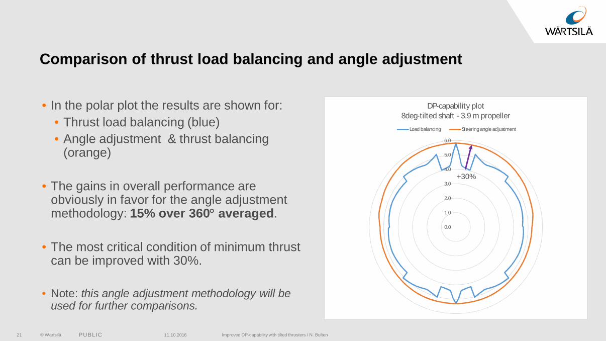
Comparison of thrust load balancing and angle adjustment
• In the polar plot the results are shown for:• Thrust load balancing (blue)• Angle adjustment & thrust balancing
(orange)
• The gains in overall performance are obviously in favor for the angle adjustment methodology: 15% over 360 averaged.
• The most critical condition of minimum thrust can be improved with 30%.
• Note: this angle adjustment methodology will be used for further comparisons.
0.0
1.0
2.0
3.0
4.0
5.0
6.0
DP-capability plot8deg-tilted shaft - 3.9 m propeller
Load balancing Steering angle adjustment
+30%

© Wärtsilä PUBLIC 11.10.2016 Improved DP-capability with tilted thrusters / N. Bulten22
Dynamic Positioning thrust polar plot
• In the polar plot the normalized available thrust results are shown for:• Reference unit – 4.1 m - 5 -nozzle (purple)• WST-55 – 3.9 m - 8 -shaft (orange)
• The WST-55U has on average over the 360circumference 3.5% more thrust for the same installed power.
• The maximum difference in DP-thrust is 6%.
Type Diameter [mm]
BP unit thrust
DP-capability (6 units)
WST-55U 3900 98.9% 103.5%Reference unit 4100 100.0% 100.0%
0.0
1.0
2.0
3.0
4.0
5.0
6.0
DP-capability plotSteering angle adjustment
8deg tilted shaft-3.9 m 5deg tilted nozzle-4.1m
Max 6%

© Wärtsilä PUBLIC
CONCLUSIONS
11.10.2016 Improved DP-capability with tilted thrusters / N. Bulten23

© Wärtsilä PUBLIC 11.10.2016 Improved DP-capability with tilted thrusters / N. Bulten24
Conclusions
• The hydrodynamic performance of thrusters with 8 -tilted shaft outperforms the industry reference design with 5 -tilted nozzle on:• Open water performance / bollard pull performance due to the alignment of propeller
and nozzle• Thruster-hull interaction losses (thrust-deduction) due to better downward deflection of
the wake.
• The difference in performance can be partly covered by larger propeller diameters, which will result in larger overall units.
• The calculated gain in DP-capability performance is 360 -averaged 3.5% and at max 6.0% when the 3.9m WST-55U is compared with the 4.1m reference unit for the same input power.

© Wärtsilä PUBLIC
Thruster unit bollard pull
Hull interaction
lossesForbidden
zonesSteering angle
adjustmentLoad
balancing
11.10.2016 Improved DP-capability with tilted thrusters / N. Bulten25
Conclusions
• In case two forbidden zones overlap as a result of interaction between 3 thrusters, the introduction of a corridor in the forbidden zones can improve the overall DP-performance.
• The thrust allocation algorithm can have a significant impact on the overall DP-capability, depending on the methods to balance the yaw-moment of the vessel.
• The differences between the load-balancing method and the steering angle adjustment is about 15% averaged over 360 and it can go up to 30% for the most critical angle.
• Future DP-systems need therefore be based on the actual net-thruster performance over its 360 azimuth sector.
