improved equipment for the treatment of feed water for modern steam boilers
TRANSCRIPT
September, 1929 INDUSTRIAL AND ENGINEERING CHEMISTRY 829
boiler water. Operating pressure was 175 pounds. Xotable i n this boiler water is the extremely high concentration of hydroxide and carbonate. Experience had taught the operators a t this plant, however, that the softener must be run with large excess of sodium carbonate in ordei to retard as far as possible formation of sulfate and silicate scale. Even so, frequent boring of tubes was necessary.
Observations were made on one boiler only, for a period of 80 consecutive hours. A check on the performance of purifier and trap was possible in this case through comparison Ivith the superheat temperature chart.
The results during the addition of the antifoam material were satisfactory. Trap discharges were not excessive in number or frequenry, and superheat temperatures were steady. Immediately after stoppage of the antifoam, how- ever, the superheat temperature fluctuated violently, and the boiler had to be blown down heavily to stop the foaming.
Experiments were made on other operating boilers, with indifferent or no success. A large enough shot of antifoam seems capable of quieting boiling conditions temporarily, but, like the drug habit, leaves the user in sad plight if successive shots are too infrequent or if continuous feed is insufficient or interrupted.
A protective measure of uncertain reliability and lacking permanence is poor insurance to superheaters, turbines, or engines. The false sense of security that may be engendered by the use of antifoaming material, the higher concentrations that may be allowed to accumulate in the boiler water, and
especially the immediateness with which disastrous conditions develop upon interrupting addition of the antifoam material constitute a compelling brief against dependence bhereon. After well-nigh three years of careful investigation into the principles governing boiling conditions, the present position of the author is defined by his statement in 1924 ( 5 ) regarding control of wet steam: “Chemical means may be used in al- leviating this coiidit’ion to a certain extent, but after all, such means merely temporize n-ith the conditions. It is advisable to consider this phase [of mater conditioning] mechanical, and use mechanical means in controlling it.” When condi- tions of careful control of alkalinity in the boiler water, sys- tematic blowdown, and cleanliness from all saponified and saponifiable materials have been realized, the next steps de- pend upon mechanical aids such as careful control of water levels, proper baffling of the steam drum, uniformity of feed- water distribution, purifiers or separators a t or beyond the steam nozzle.
Literature Cited
(1) Am. SOC. Mech. Eng., Boiler Construction Code, 1927, Sect. V I I ,
(2) Hall, IND. ENG. CHEM., 17, 283 (1925). (3) Hall, J . A m . Water W o r k s dssocn . , 21, 79 (1929). (4) Hall, Trans. Am. Ins t . Ckem. Eng., 16, Pt. 2 , 91 (1924). ( 5 ) Hall, Fisher, and Smith, Iron Steel Eng., 1, 312 (1924). (6) Parr and Straub, Illinois Eng. Expt. Sta., Bull. 166 (1926) and 177
( 7 ) Stabler, U. S. Geol. Survey, Tl’aier-Supply Paper 274, 165 (1911). (8) X’illiams and Homerburg, Ckem. “ d e l . Eng. , 30, 589 (1924).
Par. CA-5.
(1928).
Improved Equipment for the Treatment of Feed Water for Modern Steam Boilers‘
Joseph D. Yoder
WATER PURIFICATION DEPARTMENT, COCHRANE CORPORATION, PHILADELPHIA, P A .
This paper directs attention to the importance of proper feed water treatment for the modern high-pressure boiler which frequently operates a t 400 to 1200 pounds per square inch pressure and occasionally considerably higher. At - tention is directed to the value of the research investiga- tions of Parr and Straub, Hall, and Foulk, whose writings have appeared in various technical publications.
Illustrations and descriptions are given to show practical methods of treating water with phosphate to supplement the hot-process lime and soda treatment and also de- aeration. A recently developed sulfuric acid feeding equipment is described for treating boiler feed waters to give a proper relationship of sodium sulfate to sodium carbonate from the embrittlement standpoint. This equipment is adapted for use with zeolite softening or with natural waters high in sodium carbonate. The pro- portioning of sulfuric acid is accomplished by balancing the differential pressure caused by water flow through a n orifice with an air pressure which imposes a corre- sponding pressure of the sulfuric acid solution upon a small chemical orifice thus insuring a flow of sulfuric acid solution proportional to the flow of water. All parts of the equipment coming in contact with acid solution are made of lead or rubber.
A continuous blow-off equipment is described for re- moving the mineral solids as they concentrate in the boiler in such a manner as to recover the heat of the blow- off water. A steam purifier is illustrated to remove
Received July 26, 1929
moisture from the steam before the latter enters the superheater.
A conclusion is drawn tha t the modern high-pressure, high-rating boilers can be operated with satisfaction if proper equipment is installed for treatment of the boiler feed water and if i t is operated in accord with the recent disclosures of various water-purification engineers.
E HAVE entered a transition period in boiler plant design in which we are passing from the moder- vv ately high pressures of 150 and 200 pounds to 400,
600, 1200, and 1600 pounds per square inch, and even higher. Whereas industrial plants gradually increased the boiler pressures from 100 pounds to 250 pounds in forty years, they are jumping from these to the high pressures just mentioned in a few years’ time. Simultaneously with the higher boiler pressures have come higher ratings of boilers, which have been made possible by protecting the furnaces with water-cooled walls and screens.
These higher boiler pressures and ratings place exacting requirements upon feed-water treatment methods and equip- ment. The problem is emphasized by the fact that the bent tubes forming the furnace walls and roof are expensive to replace if injured by scale or corrosion, and even more costly is unexpected outage of boilers for the replacement of tubes. The high rate of evaporation within these tubes and the less active circulation a t higher pressures render even a small amount of scale more likely to burn the metal, and the bends of the tubes form likely pockets for the deposition of sludge and scale. High boiler ratings increase the tendency towards
830 ISDCSTRIAL A S D E,ITGISEERISG CHE-IIISTRY Vol. 21, No. 9
priming and delivery of met steam, for which reason it is essential that the treatment prescribed give the least incite- ment to priming and foaming.
applied, and which therefore assumes a position of equilibrium between the two impressed forces, one being downward due to the differential pressure and the other upward due to the
chemical solution pressure. The flow through
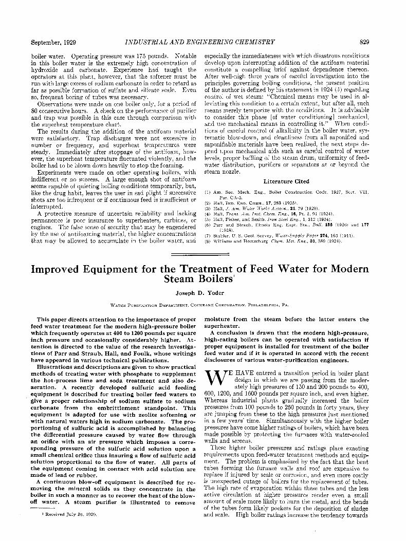
Figure 1-Hot-Process Water Softener
The higher temperatures and pressures demand serious consideration of possible embrittlement of boiler plate. Higher temperatures affect the chemical reactions, which fact, coupled with the precautions that must be taken t o guard against embrittlement, demands a careful scientific approach to the whole subject of scale prevention.
Hot-Process Lime and Soda Softener
For moderately high pressure boilers, not exceeding 250 pounds per square inch, and for the average water supply, the hot-process lime and soda softener, illustrated in Figure 1, is particularly well adapted. The value of heat in softening and settling the water is well understood and needs no further explanation.
Formerly a silica sand and gravel were universally used for filtering the hot, softened water, but it was found that the hot alkaline water, particularly if slightly caustic, dissolved an appreciable amount of silica to form sodium silicate, which in turn reacted with calcium and magnesium in the boiler and deposited as calcium and magnesium silicate scale. To overcome this dificulty a non-siliceous filtering material was developed. Both magnetite and a form of calcite were found to be suitable as filtering materials when crushed and screened to proper sizes.
The chemical feeder accomplishes the proportioning of chemicals by maintaining a pressure on a relatively small orifice a t all times proportional to the differential pressure on an orifice in the raw-water line between the regulating valve and the heater. It is thus practicable to maintain relatively high pressures on these orifices, ranging from approximately 6 inches to 18 feet of water head, which corresponds to flows from a minimum of 16 per cent to the maximum flow.
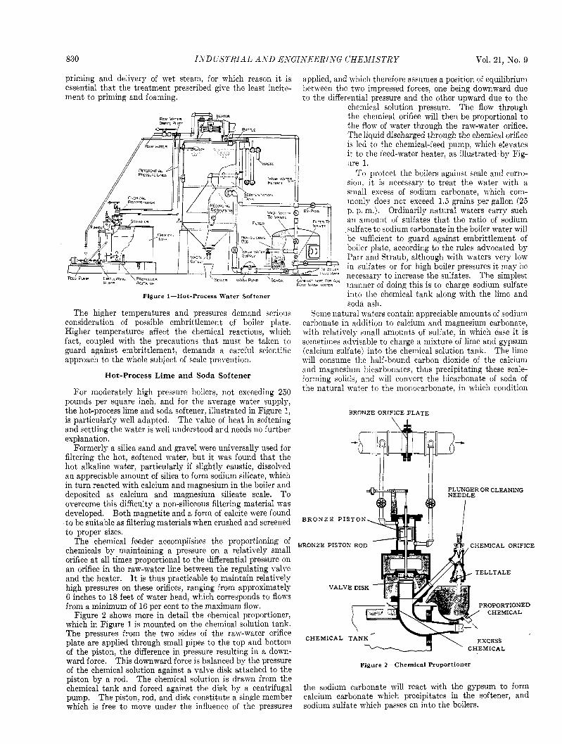
Figure 2 shows more in detail the chemical proportioner, which in Figure 1 is mounted on the chemical solution tank. The pressures from the two sides of the raw-water orifice plate are applied through small pipes to the top and bottom of the piston, the difference in pressure resulting in a down- ward force. This downward force is balanced by the pressure of the chemical solution against a valve disk attached to the piston by a rod. The chemical solution is drawn from the chemical tank and forced against the disk by a centrifugal pump. The piston, rod, and disk constitute a single member
the chemical orifice will then be proportional t o the flow of water through the raw-water orifice. The liquid discharged through the chemical orifice is led to the chemical-feed pump, which elevates it to the feed-water heater, as illustrated by Fig- ure 1.
To protect the boilers against scale and corro- sion. it is necessary to treat the water with a small excess of sodium carbonate, which com- monly does not exceed 1.5 grains per gallon (25 p. p. m.). Ordinarily natural waters carry such an amount of sulfates that the ratio of sodium sulfate t o sodium carbonate in the boiler water will be sufficient to guard against embrittlement of boiler plate. according to the rules advocated by Parr and Straub, although with waters very low in sulfates or for high boiler pressures it may be necessary t o increase the sulfates. The simplest maimer of doing this is to charge sodium sulfate into the chemical tank along with the lime and soda ash.
Some natural waters contain appreciable amounts of sodium carbonate in addition to calcium and magnesium carbonate, with relatively small amounts of sulfate, in which case it is sometimes advisable to charge a mixture of lime and gypsum (calcium sulfate) into the chemical solution tank. The lime will consume the half-bound carbon dioxide of the calcium and magnesium bicarbonates, thus precipitating these scale- forming solids, and will convert the bicarbonate of soda of the natural water to the monocarbonate, in which condition
BRONZE ORIFICE PLATE
PLUNGER OR CLEANING
B R O N Z E P I S T O N
BRONZE PISTON ROD CHEMICAL ORIFICE
TELLTALE
VALVE DISK
ROPORTIONED CHEMICAL
CHEMICAL a ' CHEMICAL
Figure 2-Chemical Proportioner
the sodium carbonate mill react with the gypsum to form calcium carbonate which precipitates in the softener, and ~.
which is free to move under the influence of the pressures sodium sulfate which passes on into the boilers.
September, 1929 INDUSTRIAL A N D EYGISEERISG CHEMISTRY 831
The phosphate is readily proportioned to the raw water by
tank with chemical proportioner shown a t the right in this illustration is the same as that previously shown in Figure 1. A tank for the phosphate solution having the same height as the tank for lime and soda ash is placed near the latter, and by means of a float and weighted chain, which rides on pulleys, a swing pipe is suspended in the phosphate tank with its open
end a t the same elevation as the level of the solu- tion in the lime and soda tank. When the lime and soda tank is charged with chemicals and water, the phosphate solution tank should be filled to the same level and charged with a proportionate amount of phosphate, as determined by tests on the boiler water.
Since the lime and soda ash are proportioned by the differential proportioner strictly in accordance with the flow of raw water, the chemical solution in the lime tank is lowered in proportion to the rate of delivering water to the softener. The float which
E rides on the surface of the lime solution lowers the swing pipe in the phosphate tank an equal amount, and thus permits the phosphate to flow through the sying pipe into the phosphate feed pump, which delivers it to a suitable point in the outlet line from the filter or into the de-aerating heater, as illustrated in Figure 4.
This method of feeding phosphate to supple- ment’ lime and soda treatment is now in satis-
factory use a t several boiler plants with pressures of 400 and 600 pounds per square inch, and has been selected at a number of other high-pressure plants not yet in ser- vice.
Phosphate Feeding Equipment
pounds per square inch and higher-as Doctor Hall has pointed out, the low solubility of calcium sulfate, coupled with the relatively large ratio of sodium sulfate. to sodium carbonate required to prevent embrittlement, ma,kes it prac- tically impossible to prevent the formation of calcium sulfate
With high-pressure boilers-that is, for pressures of 300 the equipnient in Figure 4* The lime and
FEEMNG EQUIPMEKT
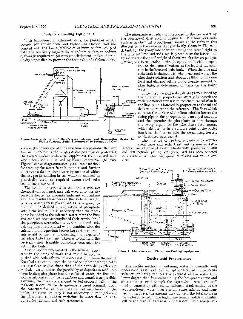
Figure 3-Arrangement of Hot-Process Softener and De-aerating Heater for
scale in the boilers and a t the same time escape embrittlement. For such conditions the most satisfactory way of protecting the boilers against scale is to supplement the lime and soda with phosphate as disclosed by Hall’s patent Kc). 1,613,656. Figure 3 shows diagrammatically a suitable method
illustrates a de-aerating heater by means of which the oxygen in solution in the water is reduced to
economizers are used. The sodium phosphate is fed from a separate
chemical solution tank and delivered into the de- aerating heat’er in amounts sufficient to combine with the residual hardness of the softened water, plus as much excess phosphate as is required to maintain the desired concentration of phosphate within the boiler. It is necessary that the phoe- phate be added t o the softened water after the lime and soda ash have accomplished their work, for if t’he phosphate were mixed with the lime and soda ash the phosphate radical would combine with the calcium and magnesium before the carbonate radi- cals would be used, thus defeating the purpose of the phosphat’e treatment, which is to maintain the necessary and desirable phosphate concentration PHOSPHATE CHEMICAL CHEMICAL
Plants Carrying Boiler Pressures of 50 Pounds and Over
for treating the water in this manner and further TO LOW PRESSURE SIDE OF r ORIFICE IN RAW WATER LINE
practically zero, as required where steel tube CHENICAL hOPORTIWER
~- -~ u- WA5HOUT -1
within the boiler. FEED PUMP FEED Pump CIRCULATING P U M P
Any phosphate precipitated in the sedimentation Figure 4-Lime-Soda and Phosphate Feeding Equipment t’ank in the doing of work that would be accom- plished with soda ash mould unnecessarily increase the cost of chemical treatment, since the cost of the phosphate radical is perhaps four or five times that of the equivalent carbonate radical. To minimize the possibility of deposits in feed lines from feeding phosphate into the softened water, the lime and soda treatment should be as uniform and complete as possible. Likewise, the phosphate should be fed proportionally to the make-up u-ater, but as dependence is based primarily upon the concentration of phosphate radical maintained in the boiler, the same accuracy is not necessary in proportioning the phosphate to sudden variations in water flow, as is re- quired for the lime and soda treatment.
Zeolite Acid Proportioners
The zeolite method of softening water is generally well understood, as it has been frequently described. The zeolite softener ordinarily reduces the hardness of the water to a lower degree than is obtainable by the hot-process lime and soda softener, even though the expression “zero hardness” used in connection with zeolite softeners is misleading, as the zeolite-softened water does contain some calcium and mag- nesium hardness, the amount varying with the total solids in the water softened. The higher the mineral solids the higher will be the residual hardness of the water. The zeolite sof-
832 INDUSTRIAL AND ENGINEERING CHEMISTRY v.01. 21, No. 9
tener is open to the objection that the sodium carbonate con- tent of the softened water may be too high to provide a ratio of sodium sulfate to sodium carbonate favorable from the embrittlement standpoint. Where a zeolite softener is used for high-pressure boilers, it is, therefore, commonly necessary to treat the softened water with sulfuric acid if the recom- mended ratios of sodium sulfate to sodium carbonate are to be maintained. Equipment for feeding sulfuric acid should embody the following features:
It should be strictly accurate and immediately responsive to sudden variations in water flow.
It should have as few parts as possible which come in con- tact with acid solution, and such parts must be made of materials known from years of usage to withstand the action of dilute sulfuric acid, such as lead and rubber.
(3) It should be dependable and adaptable to continuous service.
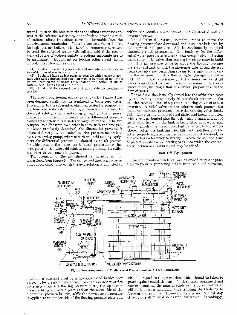
The acid-proportioning equipment shown by Figure 5 has been designed chiefly for the treatment of boiler feed water. It is similar to the differential chemical feeder for proportion- ing lime and soda ash in that both devices proportion the chemical solutions by maintaining a head on the chemical orifice a t all times proportional to the differential pressure caused by the flow of raw water through its orifice. The two equipments differ from each other in that, with the lime pro- portioner previously described, the differential pressure is balanced directly by a chemical solution pressure maintained by a circulating pump, whereas with the acid-feeding equip- ment the differential pressure is balanced by an air pressure for which reason the name “air-balanced proportioner” has been given to it. The acid solution passing through its orifice is subject to the same air pressure.
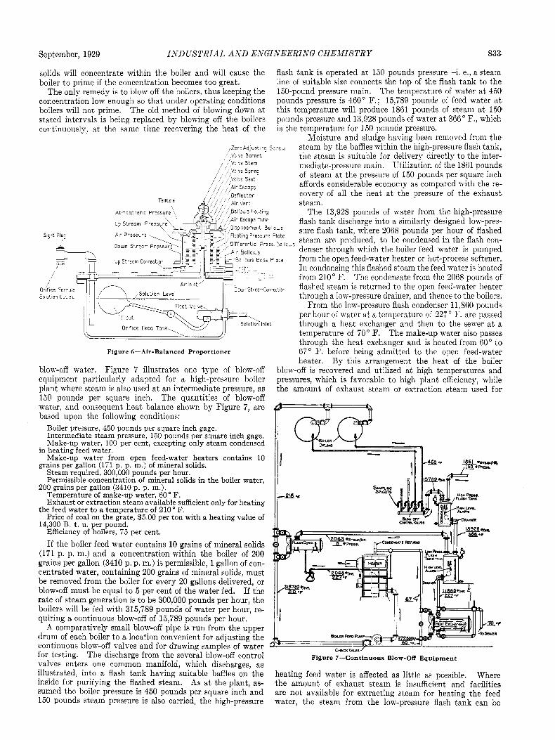
The operation of the air-balanced proportioner will be understood from Figure 6. The orifice feed tank is a cast-iron box, rubber-lined, into which the acid solution is admitted to
(1)
(2)
within the annular space between the differential and air pressure bellows.
The differential pressure, therefore, tends t o move the floating pressure plate downward and is counter-balanced by the upward air pressure. Air is continuously supplied through a small perforation. The tendency for the differ- ential water pressure is to close the air-escape valve by forcing the seat upon the valve, thus causing the air pressure to build up. The air pressure tends to move the floating pressure plate upward and, with it, the air-escape tube, lifting the seat from the valve and permitting the air to escape, thus lower- ing the air pressure. Any flow of water through the orifice will then impose a pressure on the chemical orifice at all times proportional to the differential pressure on the raw- water orifice, insuring a flow of chemical proportional to the flow of water.
The acid solution is usually forced into the orifice feed tank by maintaining approximately 30 pounds air pressure in the solution tank by means of a pressure-reducing valve set at this pressure. A relief valve on the solution tank protects the tank from excessive pressure, in case the reducing valve should fail. The solution tank is of steel plate, lead-lined, and fitted with a lead-perforated pipe through which a small amount of air is admitted while the tank is being filled with water and acid, at which time the solution tank is vented. to the atmos- phere. After the tank has been filled with solution, and the latter properly agitated, further agitation is not required, as the acid has no tendency to stratify. Above the solution tank is placed a cast-iron calibrating tank into which the concen- trated commercial sulfuric acid may be added.
Blow-Off Equipment
The equipments which have been described represent prac- tical methods of protecting boilers from scale and corrosion,
Figure 5-Arrangement of Air-Balanced Proportional Acid Feed Equipment
maintain a constant level by a float-controlled hard-rubber with due regard to the precautions which should be taken to valve. The pressure differential from the raw-water orifice guard against embrittlement. With suitable equipment and plate acts upon the floating pressure plate, the up-stream correct operation, the mineral solids in the boiler feed water pressure being above the plate and on the outer side of the will be kept a t a minimum, thus reducing the tendency to differential pressure bellows, while the down-stream pressure foaming and priming. However, there is no practical way is applied to the under side of the floating-pressure plate and of removing all mineral solids from the water. Accordingly,
September, 1929 INDUSTRIALi A X D ENGINEERING CHEMISTRY 833
solids will concentrate within the boiler and will cause the flash tank is operated a t 150 pounds pressure-i. e., a steam boiler to prime if the concentration becomes too great. line of suitable size connects the top of the flash tank to the
The only remedy is to blow off the boilers, thus keeping the 150-pound pressure main. The temperature of water a t 450 concentration low enough so that under operating conditions pounds pressure is 460" F.; 15,789 pounds of feed water at boilers ivill not prime. The old method of blowing down a t this temperature will produce 1861 pounds of steam a t 150 stated interrals is being replaced by blowing off the boilers pounds pressure and 13,928 pounds of mater at 366" F., which continuously, at the same time recovering the heat of the is the temperature for 150 pounds pressure.
Moisture and sludge having been removed from the steam by the baffles within the high-pressure flash tank, the steam is suitable for delivery directly to the inter- mediate-pressure main. Utilization of the 1861 pounds of steam at the pressure of 150 pounds per square inch affords considerable economy as compared with the re- covery of all the heat a t the pressure of the exhaust steam.
The 13,928 pounds of water from the high-pressure flash tank discharge into a similarly designed low-pres- sure flash tank, where 2068 pounds per hour of flashed steam are produced, to be condensed in the flash con- denser through which the boiler feed water is pumped from the open feed-water heater or hot-process softener. In condensing this flashed steam the feed water is heated from 210" F. The condensate from the 2068 pounds of flashed steam is returned t o the open feed-water heater through a low-pressure drainer, and thence to the boilers.
From the lowpressure flash condenser 11,860 pounds per hour of water at a temperature of 227 " F. are passed through a heat exchanger and then t o the sewer at a temperature of 70" F. The make-up water also passes through the heat exchanger and is heated from 60" to 67" F. before being admitted to the open feed-water heater. By this arrangement the heat of the boiler
blow-off is recovered and utilized a t high temperatures and pressures, which is favorable to high plant efficiency, while the amount of exhaust steam or extraction steam used for
,ZeroAd,~st '9 Sc-ew ,, ,Vclve Bcnnet
9ifferertiol F-ess B e l l o w s
r DcwnStreor rConnecton Solut on O u t l e t
Figure 6-Air-Balanced Proportioner
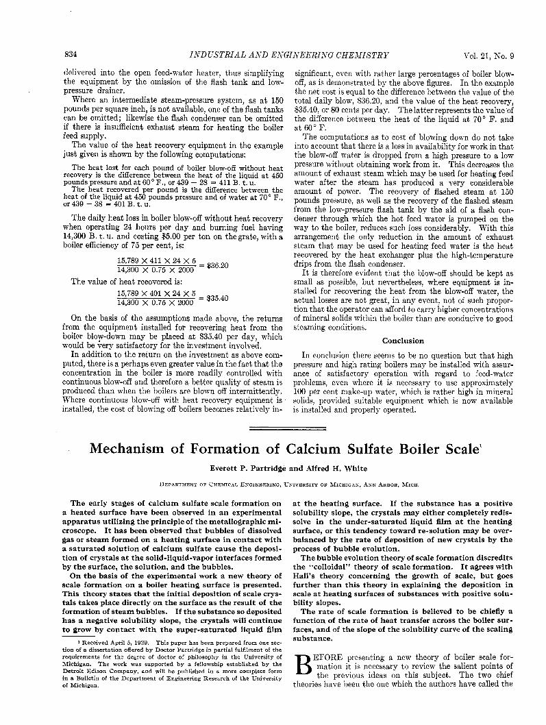
blow-off water. Figure 7 illustrates one type of blow-off equipment particularly adapted for a high-pressure boiler plant where steam is also used a t an intermediate pressure, as 150 Dounds per square inch. The quantities of blow-off water, and consequent heat balance shown by Figure 7, are based upon the following conditions:
Boiler pressure, 450 pounds per square inch gage. Intermediate steam pressure, 150 pounds per square inch gage. Make-up water, 100 per cent, excepting only steam condensed
in heating feed water Make-up water from open feed-water heaters contains 10
grains per gallon (171 p p. m.) of mineral solids. Steam required, 300,000 pounds per hour. Permissible concentration of mineral solids in the boiler water,
200 grains per gallon (3410 p. p. m.). Temperature of make-up water, 60" F. Exhaust or extraction steam available sufficient only for heating
the feed water to a temperature of 210' F. Price of coal on the grate, $5 00 per ton with a heating value of
14,300 B t u per pound Efficiency of boilers, 75 per cent.
If the boiler feed water contains 10 grains of mineral solids (171 p. p. m.) and a concentration within the boiler of 200 grains per gallon (3410 p. p. m.) is permissible, 1 gallon of con- centrated water, containing 200 grains of mineral solids. must be removed from the boiler for every 20 gallons delivered, or blow-off must be equal to 5 per cent of the water fed. If the rate of steam generation is to be 300,000 pounds per hour, the boilers will be fed with 315,789 pounds of water per hour, re- quiring a continuous blow-off of 15,789 pounds per hour.
A comparatively small blow-off pipe is run from the upper drum of each boiler to a location convenient for adjusting the continuous blow-off ralves and for drawing samples of water for testing. The discharge from the several blow-off control valves enters one common manifold, which discharges, as illustrated, into a flash tank having suitable baffles on the inside for purifying the flashed steam. As a t the plant, as- sumed the boiler pressure is 450 pounds per square inch and 150 pounds steam pressure is also carried, the high-pressure
Figure 7-Continuous Blow-Off Equipment
heating feed water is affected as little as possible. Where the amount of exhaust steam is insufficient and facilities are not available for extracting steam for heating the feed water, the steam from the low-pressure flash tank can be
834 INDUSTRIAL AXD ENGINEERING CHE-MISTRY VOl. 21, No. 9
delivered into the open feed-water heater, thus simplifying the equipment by the omission of the flash tank and low- pressure drainer.
Where an intermediate steam-pressure system, as a t 150 pounds per square inch, is not available, one of the flash tanks can be omitted; likewise the flash condenser can be omitted if there is insufficient exhaust steam for heating the boiler feed supply.
The value of the heat recovery equipment in the example just given is shown by the following computations:
The heat lost for each pound of boiler blow-off without heat recovery is the difference between the heat of the liquid at 450 pounds pressure and at 60" F., or 439 - 28 = 411 B. t. u.
The heat recovered per pound is the difference between the heat of the liquid at 450 pounds pressure and of water at 70" F., or 439 - 38 = 401 B. t. u.
The daily heat loss in boiler blow-off without heat recovery when operating 24 hours per day and burning fuel having 14,300 B. t. u. and costing $5.00 per ton on thegrate, with a boiler efficiency of 75 per cent, is:
15,789 X 411 X 24 X 5 = ~36.20 14,300 X 0.75 X 2000
The value of heat recovered is: 15,789 X 401 X 24 X 5 - ~35.40 14,300 X 0.75 X 2000
-
On the basis of the assumptions made above, the returns from the equipment installed for recovering heat from the boiler bloy-down may be placed a t $35.40 per day, which would be very satisfactory for the investment involved.
In addition to the return on the investment as above com- puted, there is a perhaps even greater value in the fact that the concentration in the boiler is more readily controlled with continuous blow-off and therefore a better quality of steam is produced than when the boilers are blown off intermittently. Where continuous blow-off with heat recovery equipment is installed, the cost of blowing off boilers becomes relatively in-
significant, even with rather large percentages of boiler blow- off, as is demonstrated by the above figures. In the example the net cost is equal to the difference between the value of the total daily blow, 836.20, and the value of the heat recovery, S35.40, or 80 cents per day. The latter represents the value of the difference between the heat of the liquid a t 70" F. and a t 60" F.
The computations as to cost of blowing down do not take into account that there is a loss in availability for work in that the blow-off water is dropped from a high pressure to a low pressure without obtaining work from it. This decreases the amount of exhaust steam which may be used for heating feed water after the steam has produced a very considerable amount of power. The recovery of flashed steam a t 150 pounds pressure, as well as the recovery of the flashed steam from the low-pressure flash tank by the aid of a flash con- denser through which the hot feed water is pumped on the way to the boiler, reduces such loss considerably. With this arrangement the only reduction in the amount of exhaust steam that may be used for heating feed water is the heat recovered by the heat exchanger plus the high-temperature drips from the flash condenser.
It is therefore evident that the blow-off should be kept as small as possible, but nevertheless, where equipment is in- stalled for recovering the heat from the blow-off water, the actual losses are not great, in any event, not of such propor- tion that the operator can afford to carry higher concentrations of mineral solids within the boiler than are conducive to good steaming conditions.
Conclusion
In conclusion there seems to be no question but that high pressure and high rating boilers may be installed with assur- ance of satisfactory operation with regard to feed-water problems, even nrhere it is necessary to use approximately 100 per cent make-up water, which is rather high in mineral solids, provided suitable equipment which is now available is installed and properly operated.
Mechanism of Formation of Calcium Sulfate Boiler Scale' Everett P. Partridge and Alfred H. White
DEPARTMENT OF CHEMICAL ENGINEERING, UNIVERSITY OF MICHIGAS, ASN ARBOR, MICH.
The early stages of calcium sulfate scale formation on a heated surface have been observed in an experimental apparatus utilizing the principle of the metallographic mi- croscope. I t has been observed tha t bubbles of dissolved gas or steam formed on a heating surface in contact with a saturated solution of calcium sulfate cause the deposi- tion of crystals a t the solid-liquid-vapor interfaces formed by the surface, the solution, and the bubbles.
On the basis of the experimental work a new theory of scale formation on a boiler heating surface is presented. This theory states tha t the initial deposition of scale crys- tals takes place directly on the surface as the result of the formation of steam bubbles. If the substance so deposited has a negative solubility slope, the crystals will continue to grow by contact with the super-saturated liquid film
1 Received April 5 , 1929. This paper has been prepared from one sec- tion of a dissertation offered by Doctor Partridge in partial fulfilment of the requirements for the degree of doctor of philosophy in the University of Michigan. The work was supported by a fellowship established by the Detroit Edison Company, and will be published in a more complete form in a Bulletin of the Department of Engineering Research of the University of Michigan.
a t the heating surface. If the substance has a positive solubility slope, the crystals may either completely redis- solve in the under-saturated liquid film a t the heating surface, or this tendency toward re-solution may be over- balanced by the rate of deposition of new crystals by the process of bubble evolution.
The bubble evolution theory of scale formation discredits the "colloidal" theory of scale formation. It agrees with Hall's theory concerning the growth of scale, bu t goes further than this theory in explaining the deposition in scale a t heating surfaces of substances with positive solu- bility slopes.
The rate of scale formation is believed t o be chiefly a function of the rate of heat transfer across the boiler sur- faces, and of the slope of the solubility curve of the scaling substance.
EFORE presenting a new theory of boiler scale for- mation it is necessary to review the salient points of B the previous ideas on this subject. The two chief
theories have been the one which the authors have called the