improved rotor flux estimation at low speeds for torque mras-based sensorless...
TRANSCRIPT

Newcastle University ePrints - eprint.ncl.ac.uk
Smith AN, Gadoue SM, Finch JW. (2015) Improved Rotor Flux Estimation at Low Speeds for Torque MRAS-Based
Sensorless Induction Motor Drives. IEEE Transactions on Energy Conversion
DOI: 10.1109/TEC.2015.2480961
Copyright:
© 2015 IEEE. Personal use of this material is permitted. Permission from IEEE must be obtained for all other uses, in any current or future media, including reprinting/republishing this material for advertising or promotional purposes, creating new collective works, for resale or redistribution to servers or lists, or reuse of any copyrighted component of this work in other works.
Link to published article:
http://dx.doi.org/10.1109/TEC.2015.2480961
Date deposited:
26/10/2015

1
Abstract— In this paper, an improved rotor flux estimation method for the Torque model reference adaptive scheme (TMRAS) sensorless induction machine drive is proposed to enhance its performance in low and zero speed conditions. The conventional TMRAS scheme uses an open loop flux estimator and a feedforward term, with basic low pass filters replacing the pure integrators. However, the performance of this estimation technique has drawbacks at very low speeds with incorrect flux estimation significantly affecting this inherently sensorless scheme. The performance of the proposed scheme is verified by both simulated and experimental testing for an indirect vector controlled 7.5kW induction machine. Results show the effectiveness of the proposed estimator in the low and zero speed regions with improved robustness against motor parameter variation compared to the conventional method.
Index Terms—Flux Estimation, induction motor, model
reference adaptive system (MRAS), sensorless vector control
NOMENCLATURE
Stator voltage in stator reference frame (V) , , Stator current / orthogonal components (A) , Stator / Rotor resistance ( ) , Stator / Rotor back EMF in stator reference
frame (V) Stator flux linkage in stator reference frame
(Wb) , , Rotor flux linkage / orthogonal components in
stator reference frame (Wb) Direct axis stator flux linkage in excitation
reference frame , , Stator / Rotor / Mutual inductances (H) , Stator current orthogonal components in
excitation reference frame (A) , Excitation frequency (electrical rad/s), angle
(electrical rad) Rotor time constant Number of pole pairs Rotor speed (mechanical rad/s)
This work was supported by Sevcon Ltd. and by the U.K.’s Engineering and Physical Sciences Research Council (EPSRC) through the Engineering Doctorate (Eng.D.) program at Newcastle University. A. N. Smith and J. W. Finch are with the School of Electrical and Electronic Engineering, Newcastle University, Newcastle upon Tyne NE1 7RU, U.K. (e-mail: [email protected]; [email protected]). S. M. Gadoue is with the School of Electrical and Electronic Engineering, Newcastle University, Newcastle upon Tyne NE1 7RU, U.K., and also with the Department of Electrical Engineering, Faculty of Engineering, Alexandria University, Alexandria 21544, Egypt (email: [email protected]).
Superscript “*” indicates demanded values
I. INTRODUCTION
NDUCTION motor drives have been a mature technology for many years, but investigations into sensorless concepts are still taking place. The basic aim of sensorless control
research is to achieve dynamic system performance equivalent to an encodered scheme without the disadvantages associated with using a speed encoder. The industry standard is rotor flux oriented vector control [1], and many applicable rotor speed estimation schemes have been proposed [2]. However, operation around, and through zero speed, is problematic and still represents a challenge. Widely used model-based sensorless methods that require the machine voltages and currents include the popular model reference adaptive schemes (MRAS) [3], of which there are many variants such as rotor flux [4], reactive power [5], back EMF [6], stator current [7], and rotor flux incorporating predictive torque control [8]. Other techniques include full and reduced order observers [9], sliding mode observers [10], and Kalman filters [11]. Artificial intelligence techniques have also been applied to sensorless control, including neural networks [12] and fuzzy logic [13]. Recent research activities in the sensorless control area include proposing new MRAS schemes [14], compensation of inverter nonlinearities [15], application of predictive control techniques [16], improving stator flux estimation [17], and enhancing the stability of flux estimators [18]. Many of the model based methods are implemented to estimate the stator or rotor fluxes, which are then used to calculate the rotational speed. However, depending on the application and range of operational speeds, limitations in the accuracy of these flux estimators can have a significant effect on the speed estimation accuracy and stability. Hence improving the flux estimation performance of these schemes can lead to a significant improvement in rotor speed estimation. Flux estimation for induction machines has been well-researched in the literature [12, 19, 20] with both simple voltage and current model estimators and more complicated schemes proposed. Voltage model flux estimators rely on the machine’s terminal voltage, current, and its parameters. This model has the simplest implementation and is inherently sensorless with no rotor speed term dependence. However, it suffers from performance limitations at low speeds concerning parameter inaccuracy and inverter nonlinearities. In addition, the need for open loop integration can cause dc offsets and
Improved Rotor Flux Estimation at Low Speeds for Torque MRAS-Based Sensorless Induction
Motor Drives Andrew N. Smith, Shady M. Gadoue and John W. Finch
I

2
drift, leading to saturation in the estimated fluxes, and consequently erroneous speed estimates. Current model flux estimates, on the other hand, depend on the machine rotor time constant and are rotor speed dependent. Many different approaches have been proposed to overcome the shortcomings of the pure integrator used in the voltage model. A common approach is to use a low pass filter (LPF) instead of the pure integrator; however, this introduces errors in magnitude and phase around the filters cut-off frequency. This can be improved by expressing the pure integrator as a fixed cut-off LPF with the inclusion of positive feedback. The authors of [19] discuss and analyze three options for flux estimation, two of which contain limiters, while the third is adaptive but requires PI tuning and is said to be suitable for high performance drives with variation in flux levels. In [10] two flux observers are proposed, a sliding mode which uses coordinate transformations, while another is based on the standard voltage models and is amended with voltage offset correction to cancel dc offsets in the flux estimate. Hinkkanen and Luomi [21] propose a method for the LPF implementation with a fixed cut-off frequency, while [22] investigates discrete rotor flux estimation techniques for MRAS schemes. In [23] a rotor flux estimator for a direct torque control (DTC) scheme is proposed that implements a correction factor based on the difference between the estimated and reference flux values. Cascaded LPF’s are fully discussed in [24] for stator flux estimation, while [25] uses three cascaded LPF’s for rotor flux estimation, each with a time constant one third of the original. Programmable LPF’s with variable cut-off frequencies have also been proposed, [26] where the cut-off varies with the excitation frequency, while [17] introduces a programmable LPF which is stated to have a simpler implementation, but similar performance to [26]. Combined current-voltage model flux observers are discussed in [20], while in [27] the authors use a pure integrator with additional offset voltage correction for stator flux estimation based on the error between the actual and demanded fluxes. Stator flux estimation for DTC is analyzed in [28, 29]. A voltage model estimator consisting of a fifth order LPF in series with a high pass filter (HPF) is shown in [28], with the combination and differentiating action of the HPF aiming to reduce the sensitivity to dc inputs and cancel the drift; [29] presents a third order LPF implementation. Results show the amplitude and phase are comparable to those from a pure integrator with the addition of zero dc gain. Discussion of the two estimators states the third order is simpler, but the fifth order achieves better harmonic filtering [28]; however, Stojic et al [17] list drawbacks of these methods including the requirement to use . Regenerative mode operation and instability of speed estimators in this region has been well documented, with different options to overcome this problem published. Harnefors and Hinkkanen [30] discuss flux and speed estimation, mentioning problems with regenerative operation and methods for stabilization. Flux estimator design is said to be critical for the success of sensorless schemes, with stator resistance the most critical parameter. Stable estimators for motoring operation are achievable, although with problems at zero speed, with instabilities that affect lower speed
regenerative operation listed. In [18] the instability challenge of regenerative operation is discussed, with investigations into the stability of a combined voltage and current model rotor flux estimator; a cross coupling feedback strategy is proposed to enable full torque / speed operation. Stator resistance variation showed stability occurs with values less than nominal, but with steady state speed error, values greater than nominal cause instability. In [31] the authors propose a solution to their adaptive flux and speed observer [32] by altering the observer gain to allow stable regenerative operation. An alternative strategy for this estimator is modification of the speed adaptive law used, an example of which is shown in [33]. Selection of the feedback gains is also studied in [34] where the authors look at the design of an adaptive full order observer to improve the stability, which [35] says is caused by unstable zeros. Stability of speed and stator resistance estimators in the regenerative region is discussed in [36, 37], mentioning how simultaneously estimating the rotor speed and stator resistance can lead to instability in the regenerative region. Analysis in [37] shows that the cross coupling between the speed and resistance estimation loops causes the instability, and that under zero / light loads and zero frequency operation correct values are not estimated. Among various techniques proposed for rotor flux and rotor speed estimation, the Torque MRAS (TMRAS) scheme was proposed in [38]. Although many papers in the literature have referred to this scheme which claims better performance, limited investigations of its performance have been presented, with it being overshadowed by other more popular MRAS schemes. In [39], the authors compared the Torque MRAS [38], rotor flux MRAS [4], and an adaptive flux observer [32] to a set of low speed stepped tests and load impacts, with the effect of parameters and stability discussed. Ohyama et al [40] presents a small signal stability analysis of the TMRAS scheme in [38] looking at three different current control loops. Since this, no more work has been carried out to further investigate the performance of the TMRAS scheme especially at low speeds and during regenerative operating conditions. Unlike other methods the TMRAS scheme is inherently sensorless and cannot be operated open loop. In this scheme the rotor speed is estimated using a PI controller in order to minimize the error between the torque producing current demand generated by the speed loop and that calculated via the TMRAS scheme. Rotor flux estimation is an important consideration for this scheme, especially at low speeds, where erroneous flux estimates lead to problems with not only the rotor flux control loop (if used) and the feed forward slip calculation term for indirect vector control operation, but more importantly the estimation of the torque producing current and hence rotational speed. These effects destabilize the whole vector control based system, causing incorrect orientation even for correct machine parameters; hence accurate flux estimation is crucial for this scheme. This paper presents a detailed investigation of the low speed operation of the TMRAS scheme including regenerative capability. First, the theoretical concept and implementation of the scheme is described. Then the rotor flux estimation is analyzed, with problems affecting the estimation, especially at low speeds, discussed.

3
Figure 1: Block diagram of the conventional Torque MRAS scheme
Figure 2: Overall sensorless vector control drive system block diagram An improved rotor flux estimator is proposed to enhance the low speed operation of the scheme. Simulation results are given to compare the performance of the proposed and the conventional schemes. Finally, experimental results, based on a 7.5kW induction machine drive, are shown to validate the proposed scheme for both motoring and regenerative operation, with the effect of parameter variation on the scheme’s low speed performance discussed. This paper is organized into six sections. In Section II, the basic theory of the conventional Torque MRAS scheme is presented. Section III introduces the proposed flux estimator for improved performance. Simulation and experimental results are presented in Sections IV and V respectively, while Section VI concludes the work.
II. TORQUE MRAS (TMRAS) SCHEME The block diagram of the conventional TMRAS scheme is shown in Fig. 1. A simple voltage model using the measured stator currents and reference stator voltages is used to estimate the rotor flux components in the stator reference frame. Using these and the reference flux term, a rotor flux estimate in the excitation reference frame and the torque producing current are calculated; this current is then compared to that from the rotor speed PI loop. The error from this comparison is minimized by another PI controller which generates the estimated rotor speed ( ); this is then used in the rotor speed control loop and angle transformation calculations for the vector control scheme.
As the scheme is implemented in Figs. 1 and 2 which is identical to [39], five PI controllers are needed, and this could be seen to be a disadvantage with commissioning. However, three of these are standard to vector controlled systems being used for the d/q current and speed loops and widely known methods for their tuning exist. The fourth is used to control the rotor flux loop and is commonly used, while the fifth is used for rotor speed estimation, but unlike other methods [4, 32] which can be tuned offline, online tuning has to occur with this method. Rotor flux estimation is achieved by integrating the back EMF:
(1)
To avoid the pure integration problems, a standard integration method is to express the pure integrator as a fixed cut-off LPF with the inclusion of positive feedback:
(2)
However, in [38] instead of a feedback term, a feed forward reference term is used to estimate the rotor flux in the stator reference frame:
(3)
The gains of the filters differ; at low excitation frequencies the right hand reference term dominates and . This deactivates the closed loop rotor flux controller shown in Fig.
11sTc
ssv
ssi
sR
r
ms L
LL2
1sTT
c
c
22_
)(sqr
sdr
sds
sqr
sqs
sdre
TMRASqs
iii
sqs
sqr
sds
sdrm
eTMRASdr iiL_
dtd
m
r
LL s
re
*_
srefr
*eqsi
eTMRASdr _
estr _
eTMRASqsi _
sLPFr _
sr
*edr
0*eqr
srefr _
eje
e
je
je 2
23
3
dtee
edsv
eqsv
*sqsv
*sdsv
edsi
eqsi
sdsi
sqsi
r
*r
eTMRASdr_
*edr
*edsi
*eqsi
slip
*edsv
*eqsv
eTMRASdr
eqs
r
m iTL
_
*e
estr _
estr _
estr _
*eqsi *e
dr
r
eTMRASdr_
eTMRASdr_
eTMRASdr_

4
2; as the frequency increases the filters gain reduces, but increases, so the left hand side term dominates and closed loop rotor flux control is achieved. In [38], to reduce the error caused by resistive parameter variation, and this has been used for this analysis, leading to:
(4)
The rotor flux estimates are in the stator reference frame, while the vector control uses the excitation reference frame. The full equation for the TMRAS rotor flux estimate (similar to that of [40, 41]) is:
(5)
which is comparable to the standard version used for vector control:
(6)
Equation (5) can be simplified for steady state operation as the constant torque operating region is being analyzed, this also allows comparison with the results of [39]:
(7)
Using basic trigonometric relationships for the rotor flux, the Park transformation, and manipulating for , the estimated torque producing current used for the scheme is derived as:
(8)
Rotor flux oriented vector control is a closed loop scheme; any errors in the measured stator currents due to drift and dc offset are compensated by the current loop PI controllers. However, this causes problems as the stator voltages demanded to remove these offsets are used for the flux estimation, and these corrections give offsets in the flux estimation, which has implications for the TMRAS scheme. The inverter nonlinearities are also a major consideration at low excitation frequencies; unless comprehensive compensation is included, the voltage drop of the inverter forces the control to request a higher voltage which affects the flux estimate. Of the many integrator methods proposed in literature, limited publications look at applicable schemes with the rotor flux estimated using a feed forward term.
III. PROPOSED ROTOR FLUX ESTIMATOR Due to the specific operation of the TMRAS flux estimator with feedforward operation, inclusion of a HPF with a very low cut-off frequency placed after the LPF removes the dc offset without affecting the overall rotor flux estimate. A diagram showing its placement can be seen in Fig. 3. This filter also overcomes another inherent problem with this estimator configuration. When the reference LPF will be providing the desired value; however, the LPF is also estimating rotor flux, although not necessarily at the correct
value. This is due to the inverters nonlinearities and the accompanying voltage drop leading to increased voltage demands. Even though inverter compensation schemes have been proposed, exact compensation is not possible, hence erroneous rotor flux estimation will always occur.
Figure 3: Proposed rotor flux estimator block diagram
The effects of the additional series HPF and for the LPF’s allow (4) to be expressed as:
(9)
The gain and phase responses of the new LPF loop can be seen in Fig. 4. The decoupling effect of the HPF at low excitation frequencies is easily understood on the magnitude plot via the significantly reduced gain. The additional HPF causes a 90o phase shift at the low values of ; but here the reference term is controlling the flux estimate and no overall effect is observed. As the frequency increases, the gain of the combined filter combination increases, the phase difference decreases, and magnitude equal to the LPF is achieved. At the same time the stator voltage is also increasing and the series filter combination starts controlling the rotor flux estimate and the indirect vector control scheme.
Figure 4: Bode Plot of the proposed flux estimator. (a) Magnitude, (b) Phase
11sTr
1sTT
r
rs
re
*_
srefr
1sTsT
c
cs
LPFr _s
rs
HPFr _
srefr _
10−2
10−1
100
101
102
103
−90
−45
0
45
90
Excitation frequency (rad/s)
Phas
e (d
eg)
10−2
10−1
100
101
102
103
−60−50−40−30−20−10
010
Excitation frequency (rad/s)
Mag
nitu
de (d
B) ψ
rs
ref
ψrs
LPFψ
rs
HPF
ψrs
ref
ψrs
LPFψ
rs
HPF
(a)
(b)

5
IV. SIMULATION RESULTS The response of the proposed torque current estimator to a 10A step demand with open loop encodered operation is shown in Fig. 5. Compared to the demanded and actual torque producing currents the estimator responds well, only taking 2ms to reach the demanded value. For comparison and to prove the scheme, the performance and simulated behavior of the conventional TMRAS is presented in Fig. 6, based around a 7.5kW, 415V, 50Hz, delta connected induction machine with an inverter switching frequency of 15kHz whose parameters are shown in the appendix. Results of the TMRAS rotor speed, flux estimates, and excitation reference frame currents, to a test based on [39] requiring multiple field oriented torque operations are shown, with the test consisting of a set of 3.14 rad/s steps from 15.7 rad/s to zero and back to 15.7 rad/s with imperfect inverter compensation and no external load. The rotor flux estimate is compared to the standard flux estimation equation of (6). The effect of an imperfect inverter is easily seen with the increased rotor flux estimate (see Fig. 6 (d)) at zero speed (3-6s). Due to the combined effect of the reference and LPF flux estimates, a 73% error in the flux is observed, is also halved (see Fig. 6 (e)) compared to its rated value as the flux PI controller reduces the erroneous estimated value leading to incorrect magnetizing of the machine and an incorrect slip term. With a speed demand, the associated increased stator voltage, and reduction of the reference term causes the rotor flux estimate and terms to correct themselves, but this correction leads to severe oscillation in both the accelerating region and . It should be noted that as reduces, the error in the rotor flux increases again (easily seen in Fig. 6 (e)) with its effect on the currents (see Fig. 6 (f)). Fig. 7 shows the no load simulated responses of the proposed modified scheme with the HPF; Figs. 7 (d) and (e) show that the estimated stator and excitation reference frame fluxes are now correct, with minimal error between those calculated using (6) and (7). The LPF still estimates a flux (see Fig. 7 (c)) due to the inverter, but its effect is now negligible. With a speed demand significantly reduced errors are seen in the rotor speed and excitation flux estimates as no correction of the rotor flux, slip calculation, and torque producing current, are needed. These results prove that the inclusion of the HPF has solved both the dc offset / drift and inverter voltage drop problems at very low rotor speeds for this rotor flux estimation scheme, allowing correct field oriented control to occur.
Figure 5: Torque-current Step Response
Figure 6: Simulated conventional TMRAS with no load, 15.7 to 0 to 15.7 rad/s, 3.14 rad/s Steps, and Nominal values. a) rotor speed responses, b) reference flux estimate, c) LPF flux estimate, d) overall flux estimate, e) excitation reference frame flux estimates, f) excitation reference frame currents
2.996 2.998 3 3.002 3.004 3.006 3.008 3.0102468
1012
Time (s)
Cur
rent
(A)
iqse *
iqse
iqse
TMRAS
2 4 6 8 10 12 14 16 18 20 22 24 26 28 30 32−4
0
4
8
12
16
Time (s)
Cur
rent
(A)
2 4 6 8 10 12 14 16 18 20 22 24 26 28 30 320
0.20.40.60.8
11.21.4
Time (s)
ψdre
(Wb)
2 4 6 8 10 12 14 16 18 20 22 24 26 28 30 32−2
−1
0
1
2
Time (s)
ψrs (W
b)
2 4 6 8 10 12 14 16 18 20 22 24 26 28 30 32−2
−1
0
1
2
Time (s)
ψrs (W
b)
2 4 6 8 10 12 14 16 18 20 22 24 26 28 30 32−2
−1
0
1
2
Time (s)
ψrs (W
b)
2 4 6 8 10 12 14 16 18 20 22 24 26 28 30 32−5
0
5
10
15
20
Time (s)
ωr (
rad/
s)
ωr*
ωr
ωr est
ψdrs
refψ
qrs
ref
ψdrs
LPFψ
qss
LPF
ψdrs ψ
qrs
ψdre
ψdre
TMRAS
idse * i
qse *
(a)
(b)
(c)
(d)
(e)
(f)

6
Figure 7: Simulated proposed TMRAS with no load, 15.7 to 0 to 15.7 rad/s, 3.14 rad/s Steps, and Nominal values. a) rotor speed responses, b) reference flux estimate, c) LPF flux estimate, d) overall flux estimate, e) excitation reference frame flux estimates, f) excitation reference frame currents
Figure 8: Simulated proposed TMRAS with 25% load, 15.7 to 0 to 15.7 rad/s, 3.14 rad/s Steps, and Nominal values a) rotor speed responses, b) reference flux estimate, c) LPF flux estimate, d) overall flux estimate, e) excitation reference frame flux estimates, f) excitation reference frame currents
2 4 6 8 10 12 14 16 18 20 22 24 26 28 30 32−4
0
4
8
12
16
Time (s)
Cur
rent
(A)
2 4 6 8 10 12 14 16 18 20 22 24 26 28 30 320
0.20.40.60.8
11.21.4
Time (s)
ψdre
(Wb)
2 4 6 8 10 12 14 16 18 20 22 24 26 28 30 32−2
−1
0
1
2
Time (s)
ψrs (W
b)
2 4 6 8 10 12 14 16 18 20 22 24 26 28 30 32−2
−1
0
1
2
Time (s)
ψrs (W
b)
2 4 6 8 10 12 14 16 18 20 22 24 26 28 30 32−2
−1
0
1
2
Time (s)
ψrs (W
b)
2 4 6 8 10 12 14 16 18 20 22 24 26 28 30 32−5
0
5
10
15
20
Time (s)
ωr (
rad/
s)
ωr*
ωr
ωr est
ψdrs
refψ
qrs
ref
ψdrs
LPFψ
qss
LPF
ψdrs ψ
qrs
ψdre
ψdre
TMRAS
idse * i
qse *
(a)
(b)
(c)
(d)
(e)
(f)

7
Responses to loaded dynamic steps for the modified scheme are shown in Fig. 8. Fig. 8 (a) shows the load is held throughout the test, although with small errors at low and zero rotor speeds. reduces with speed until the inverter nonlinearities come into effect, leading to errors in the rotor speed and torque currents, although as Fig. 8 (d) shows, even with load, the flux estimation is correct as with the no load response of Fig. 7 (d).
Figure 9: Simulated responses to variation in speed and load demands for motoring operation. and Nominal values. a) rotor speed responses, b) external load torque, c) overall flux estimate, d) excitation reference frame currents
Figs. 9 and 10 show proposed TMRAS responses to a wider variation in load torque and rotor speed for both motoring and regenerative regions of operation. Fig. 9 shows the responses of the rotor speed, rotor fluxes, and stator currents to a speed demand of 15.7 rad/s with 25% load, increasing to 78.5 rad/s, a change to 75% load, and then a speed reduction to 26.2 rad/s, showing stable operation with correct flux estimation. Fig. 10 shows a more complicated set of load torques for operation in the negative speed region, with both motoring and regenerative operation occurring. Regenerative operation is occurring at 6.5s with -6.28 rad/ and 25% load, and at 12s with 26.2 rad/s and 75% load before a severe load torque reversal
from 75% to -50% occurs at 15 seconds. The flux and current responses show the schemes capability of handling regenerative operation and large load changes.
Figure 10: Simulated responses to variation in negative speed and load demands for both motoring and regenerative operation. and Nominal values. a) rotor speed responses, b) external load torque, c) overall flux estimate, d) excitation reference frame currents
Further results comparing the performance of the conventional and proposed TMRAS schemes are shown in Figs. 11 and 12 for a sequence of external load step changes of 0 to 25%, 25% to -25%, -25% to 0, 0 to -25%, and finally 0 to 75% at zero rotor speed demand. The conventional scheme (see Fig. 11) shows errors in the rotor speed up to 25 rad/s with the initial 25% load torque impact, before the rotor speed settles with a steady state error of 1.5 rad/s compared to an error of 3.6 rad/s with a load of -25%. Failure occurs when 75% load is applied at 27 seconds. The previously mentioned effects of the inverter on the overall flux estimates, excitation fluxes, and excitation currents are shown in Figs. 11 parts (c) through (e) respectively. Errors up to 70% in the overall flux estimates at start-up are shown in part (c), reducing to 45% during operation. A maximum error of 40% (0.44Wb) occurs in the excitation flux, which varies with operation, meaning correct magnetization is not occurring, leading to the incorrect
2 4 6 8 10 12 14 16 18 20 22 24 26 28 30 32−2
02468
10121416
Time (s)
Cur
rent
(A)
2 4 6 8 10 12 14 16 18 20 22 24 26 28 30 32−1.5−1
−0.50
0.51
1.5
Time (s)
ψrs (W
b)
2 4 6 8 10 12 14 16 18 20 22 24 26 28 30 3205
10152025303540
Time (s)
Torq
ue (N
m)
2 4 6 8 10 12 14 16 18 20 22 24 26 28 30 320
102030405060708090
Time (s)
Rot
or S
peed
(rad
/s)
ω r*
ω rωr est
Tload
ψdrs
ψqrs
idse *
iqse *
(a)
(b)
(c)
(d)
2 4 6 8 10 12 14 16 18 20 22 24 26 28 30 32−16−12−8−4
048
1216
Time (s)
Cur
rent
(A)
2 4 6 8 10 12 14 16 18 20 22 24 26 28 30 32−1.5−1
−0.50
0.51
1.5
Time (s)
ψrs (W
b)
2 4 6 8 10 12 14 16 18 20 22 24 26 28 30 32−40−30−20−10
010203040
Time (s)
Torq
ue (N
m)
2 4 6 8 10 12 14 16 18 20 22 24 26 28 30 32−50−40−30−20−10
0
Time (s)
Rot
or S
peed
(rad
/s)
ω r*
ω rωr est
Tload
ψdrs
ψqrs
idse *
iqse *
(a)
(b)
(c)
(d)

8
Figure 11: Simulated conventional TMRAS with zero rotor speed demand and varying loads, and Nominal values. a) rotor speed responses, b) load torque applied, c) overall flux estimate, d) excitation reference frame flux estimates, e) excitation reference frame currents
operation and speed estimation. In comparison, the effect of adding the HPF term (see Fig. 12) shows the proposed scheme can tolerate the load torque impacts with small errors in the rotor speed. At 25% load, a maximum error of 0.8 rad/s was shown before slowly converging to zero, while 1 rad/s occurred at -25% load. With 75% torque applied the scheme fails. Correct flux estimates are achieved in both the stator and excitation reference frames leading to correct magnetization of the machine. The effect of the orientation error mentioned for Fig. 8 is also shown for in Fig. 12 (e).
Figure 12: Simulated proposed TMRAS with zero rotor speed demand and varying loads, and Nominal values. a) rotor speed responses, b) load torque applied, c) overall flux estimate, d) excitation reference frame flux estimates, e) excitation reference frame currents
Dynamic stiffness is a term used to describe the robustness of a system [42]. In [42], it was used to find the torque disturbance required to produce a per unit error in the rotor speed ( ). Here, the stiffness of the torque current estimator was analyzed by finding the load torque disturbance that produced a per unit error in the current. Since the TMRAS scheme is inherently sensorless and cannot operate open loop, the open loop stiffness of the torque current estimator was found using an encodered vector control scheme. A 12Nm (25%) constant load was applied with an additional 3Nm chirp signal varying from 0 to 100Hz. From Fig. 13 it can be seen that there is limited variation in the
4 6 8 10 12 14 16 18 20 22 24 26 28 30 32−10
0
10
20
30
Time (s)
Cur
rent
(A)
4 6 8 10 12 14 16 18 20 22 24 26 28 30 320
0.20.40.60.8
11.21.4
Time (s)
ψdre
(Wb)
4 6 8 10 12 14 16 18 20 22 24 26 28 30 32−2
−1.5−1
−0.50
0.51
1.52
Time (s)
ψrs (W
b)
4 6 8 10 12 14 16 18 20 22 24 26 28 30 32−50−25
0255075
100
Time (s)
Torq
ue (%
)
4 6 8 10 12 14 16 18 20 22 24 26 28 30 32−25−20−15−10−5
05
10152025
Time (s)
ωr (
rad/
s)
ωr* ω
rω
r est
Tload
ψdrs ψ
qrs
ψdre
ψdre
TMRAS
idse * i
qse *
(a)
(b)
(c)
(d)
(e)
4 6 8 10 12 14 16 18 20 22 24 26 28 30 32−10−5
05
10152025
Time (s)
Cur
rent
(A)
4 6 8 10 12 14 16 18 20 22 24 26 28 30 320
0.20.40.60.8
11.21.4
Time (s)
ψdre
(Wb)
4 6 8 10 12 14 16 18 20 22 24 26 28 30 32−2
−1.5−1
−0.50
0.51
1.52
Time (s)
ψrs (W
b)
4 6 8 10 12 14 16 18 20 22 24 26 28 30 32−50−25
0255075
100
Time (s)
Torq
ue (%
)
4 6 8 10 12 14 16 18 20 22 24 26 28 30 32−5
0
5
10
Time (s)
ωr (
rad/
s)
ωr* ω
rω
r est
Tload
ψdrs ψ
qrs
ψdre
ψdre
TMRAS
idse * i
qse *
(a)
(b)
(c)
(d)
(e)

9
responses, with the ability to tolerate torque disturbances reducing slightly with the increase in rotor speed.
Figure 13: Simulated dynamic stiffness of torque current estimator with encodered operation
V. EXPERIMENTAL RESULTS For comparison and validation of the simulation results, experimental testing was carried out using a 7.5kW induction machine whose parameters are given in the appendix, loaded by a 9kW, 240V, 37.5A separately excited dc machine, and controlled via a dSpace DS1103 prototyping system. Hall effect current sensors were used to measure the motor line currents, while the actual motor speed was measured by a 5000 pulses/revolution incremental optical encoder. The vector control drive was always running in sensorless mode, while the HPF cut off frequency was set to 1Hz after experimentation. This value was chosen due to the effects that
has on the system. If is too small, then the erroneous flux estimates calculated due to the nonlinearities will be passed before their effect has reduced. Too big a value will mean that the reference values will have dropped too low before the estimated values are incorporated, giving incorrect flux control and speed estimation. Hence the selection of is a compromise between these two effects. Comparative tests based on those given in [39] were implemented, and results are shown in Figs. 14-17. During testing, the slew rate of the machine was limited to 26.2 rad/s2. Dynamic testing showing the field orientated control at low speeds is obtained via stepped responses from 15.7 rad/s to 0 and back to 15.7 rad/s with 3.14 rad/s steps lasting 1s and similar stepped responses going from 15.7 to 15.7 rad/s. For the testing the load torque was always in the same direction, with the load opposing the motion for positive speed demands, and regeneration occurring when the speed and torque have different signs.
A. Start-up Performance Figs. 14 and 15 show the experimental reference, estimated, and actual rotor speeds and the reference, calculated, and overall rotor flux estimates from the filters. These allow verification of the simulated results and the proposed system, presenting the aforementioned effect of erroneous flux estimation on the rotor speed at start-up to 15.7 rad/s with no applied external load. The effect of the inverter voltage drop on the flux calculation is easily shown for the conventional TMRAS in Fig. 14 parts (b) to (d) with both the reference and LPF components estimating flux terms, which cause errors in
and the slip calculation. Once the speed demand is applied, the flux estimates return to correct values, but during
this correction period, discrepancies in the rotor speed are seen. Fig. 15 shows the proposed TMRAS with the effect of including the HPF in the flux calculation. The flux estimate of the LPF and HPF loop combination is presented in Fig. 15 (c); with the overall effect shown in Fig. 15 (d). The significant improvement in accuracy of the overall flux estimate allows quicker and more accurate tracking of the speed demand, with a significant reduction in oscillation.
B. Low Speed Performance The results of experimental step changes in the rotor speed of the proposed TMRAS from 15.7 to 0 and back to 15.7 rad/s are presented in Fig. 16. Fig. 16 (a) shows the responses with no load and Fig. 16 (b) with 25% load. This shows the capability of the scheme to a set of field oriented torque step changes in the motoring region. The torque capabilities of the scheme can also be seen in Fig. 16 (b); this shows the scheme can hold zero speed with applied load torque, but with a small average error of 0.8 rad/s in estimated speed as shown in the zoomed in inset. Once the 3.14 rad/s demand is applied, errors of 0.39 rad/s and 1.84 rad/s for the estimated and measured speeds respectively are obtained with accurate control occurring as the speed increases. Fig. 17 shows the performance of the proposed scheme to regenerative operation with a set of negative going step changes in the reference speed through zero speed; part (a) shows the effect with no load, and (b) with 25% load. As with Fig. 16, slight estimation errors of the same magnitude are shown passing through zero speed with small oscillations occurring at ±3.14 rad/s and an error of 1.06 rad/s at -3.14 rad/s, but the load torque is controlled, showing this proposed scheme can successfully operate in the regenerative region.
C. Effect of Parameter Variation The effect of stator resistance and rotor resistance parameter variation up to ±50% on the proposed scheme for the tests discussed in Section IV is summarized in Tables I and II, where “Conv” means the conventional TMRAS results from [39], “Prop” means the proposed TMRAS, ‘ ’ means successful, ‘ ’ failure, ‘R’ recovers, and “Osc” is an oscillatory response. These results are a more thorough testing of parameter variation than those in [39] for the conventional TMRAS, where only variation of ±20% was shown. The zero and 25% load results are from practical testing, while the 50% is from validated simulated responses. Parameter adaptation schemes are often used for control algorithms, but the tests shown here are primarily to investigate the effect of incorrect parameters and the schemes robustness to these errors, while [41] states no method for stator resistance tuning for the TMRAS scheme has been reported. This could be a further research area. The results of Table I show operation up to 50% load is achievable for positive speed variation when is nominal or overestimated, although at 150% nominal, oscillation occurs. For regenerative operation the test is passed when is nominal, or 120% of nominal.
100
101
102
10−1
100
Frequency (Hz)
T d / i qse
(Nm
/ A
)
10 rad/s
25 rad/s
50 rad/s

10
Figure 14: Experimental start-up performance at no-load, Conventional TMRAS, a) rotor speed responses, b) reference flux estimate, c) conventional flux estimate, d) overall flux estimate
Figure 16: Experimental motoring performance of Proposed TMRAS, 15.7 to 0 to 15.7 rad/s Steps, a) No Load, b) 25% Load
Figure 15: Experimental start-up performance at no-load, Proposed TMRAS, a) rotor speed responses, b) reference flux estimate, c) Proposed flux estimate, d) overall flux estimate
Figure 17: Experimental regenerative performance of Proposed TMRAS, 15.7 to -15.7 rad/s Steps, a) No Load, b) 25% load
0 0.5 1 1.5 2 2.5 3 3.5 4 4.5 5−2
−1.5−1
−0.50
0.51
1.52
2.53
Time (s)
ψrs (W
b)
0 0.5 1 1.5 2 2.5 3 3.5 4 4.5 5−2
−1.5−1
−0.50
0.51
1.52
2.53
Time (s)
ψrs (W
b)
0 0.5 1 1.5 2 2.5 3 3.5 4 4.5 5−2
−1.5−1
−0.50
0.51
1.52
2.53
Time (s)
ψrs (W
b)
0 0.5 1 1.5 2 2.5 3 3.5 4 4.5 5−10
0102030405060
Time (s)
Rot
or S
peed
(rad
/s)
ω r*
ω rωr est
ψdrs
refψ
qss
ref
ψdrs
LPFψ
qrs
LPF
ψdrs
ψqrs
(a)
(b)
(c)
(d)
10 15 20 25 30−5
05
101520
Time (s)
Rot
or S
peed
(rad
/s)
15 20−2
0246
10 15 20 25 30−5
05
101520
Time (s)
Rot
or S
peed
(rad
/s)
15 20−2
0246
ω r*
ω rωr est
ω r*
ω rωr est
(a)
(b)
0 0.5 1 1.5 2 2.5 3 3.5 4 4.5 5−2
−1.5−1
−0.50
0.51
1.52
2.53
Time (s)
ψrs (W
b)
0 0.5 1 1.5 2 2.5 3 3.5 4 4.5 5−2
−1.5−1
−0.50
0.51
1.52
2.53
Time (s)
ψrs (W
b)
0 0.5 1 1.5 2 2.5 3 3.5 4 4.5 5−2
−1.5−1
−0.50
0.51
1.52
2.53
Time (s)
ψrs (W
b)
0 0.5 1 1.5 2 2.5 3 3.5 4 4.5 5−10
0102030405060
Time (s)
Rot
or S
peed
(rad
/s)
ω r*
ω rωr est
ψdrs
refψ
qss
ref
ψdrs
HPFψ
qrs
HPF
ψdrs
ψqrs
(a)
(b)
(c)
(d)
10 15 20 25 30−20−15−10−5
05
101520
Time (s)
Rot
or S
peed
(rad
/s)
15 20−6−4−2
0246
10 15 20 25 30−20−15−10−5
05
101520
Time (s)
Rot
or S
peed
(rad
/s)
15 20−6−4−2
0246
ω r*
ω rωr est
ω r*
ω rωr est
(a)
(b)

11
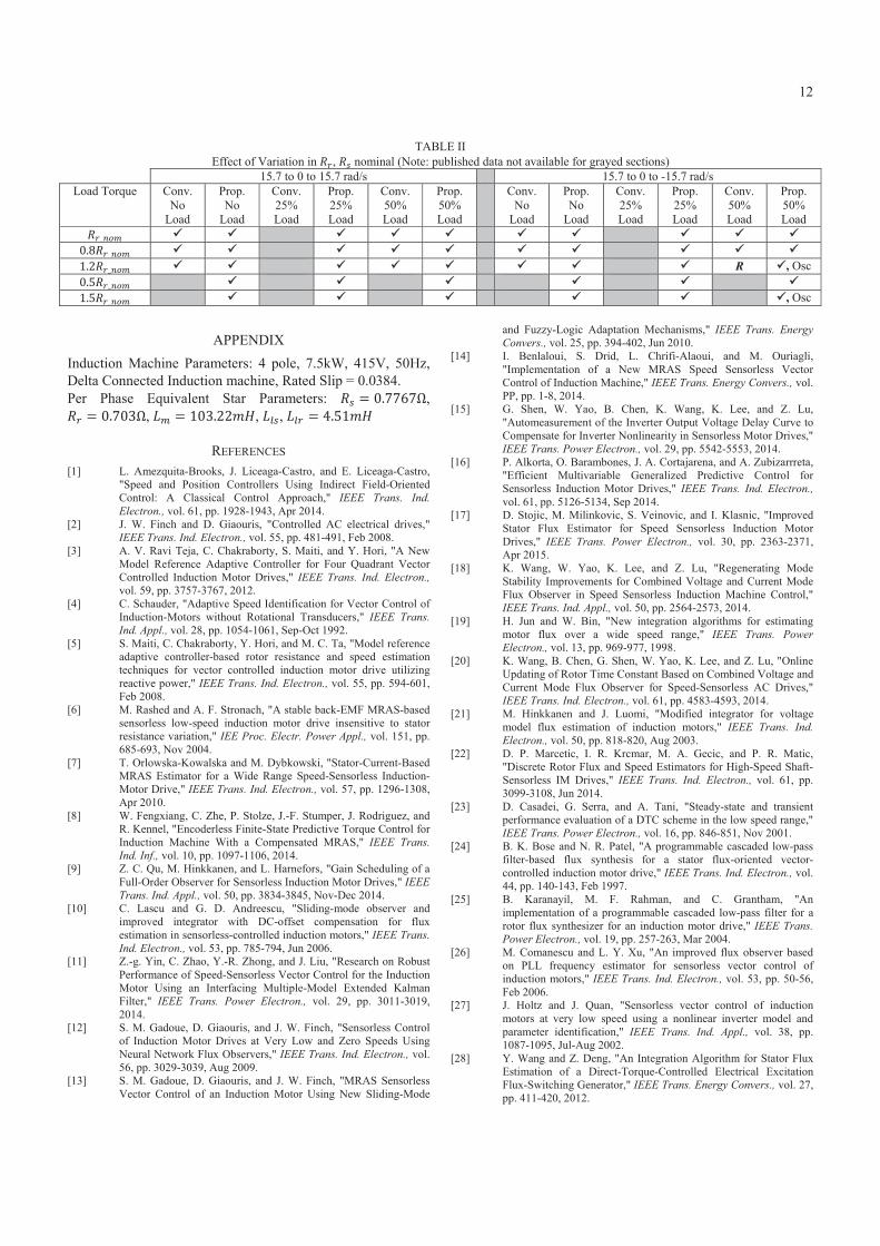
The results shown in Table II and [39] show that the variation in rotor resistance has less effect on the schemes ability to complete the stepped tests than the stator resistance; although the variation does affect the indirect slip estimation calculation and the time constant for the TMRAS filters leading to variation in the steady state speeds obtained. These results show that the proposed system is superior to the conventional TMRAS with an extended operating range not only against higher load torques but also against stator resistance variation. Previously, with nominal parameters both motoring and regenerative tests were passed with loads up to 50%; while with 80% stator resistance the motoring test was passed with 50% load and the regenerative tests at no load condition. Testing now shows regenerative operation up to 25% load can be held, with failure occurring in the range of 25-50% load. For the conventional scheme and 120% resistance, no test was passed with any value of load; now both tests are satisfactorily completed with up to 50% load, a significant improvement.
D. Rotor Flux MRAS / TMRAS Comparison Fig. 18 shows an experimental comparison between the proposed TMRAS scheme and the well-known Rotor Flux MRAS by Schauder [4]. Although the proposed scheme (part (b)) has a slightly more oscillatory response, it is superior in the speed transient region and more accurate with the lower -3.14 rad/s speed demand.
Figure 18: Experimental comparison for a No Load, -3.14 rad/s to -6.28 rad/s step change. a) Rotor Flux MRAS, b) Proposed TMRAS
E. TMRAS Torque-Speed Operating Regions Fig. 19 shows the torque/speed operating regions for the proposed TMRAS scheme validated with experimental data. This shows the stable and unstable regions for various load torques at low speed operation. In regenerative operation both the machine and the load are rotating in the same direction with the load machine overcoming the frictional and inertial components, leaving additional current for the TMRAS scheme to regulate the speed at higher loads. Minor errors may also occur in the flux estimate in regenerative operation at higher loads, leading to increased flux producing current and higher torque capability.
Figure 19: Torque/Speed Operating Regions
VI. CONCLUSION In this paper, a new rotor flux estimator for the TMRAS scheme was proposed. Both simulation and experimental results are shown for the sensorless vector control drive operating at low and zero speeds, with both motoring and regenerative operations considered. These results have illustrated stable sensorless performance as this scheme achieves a more accurate rotor flux estimation using the feedforward method inherent to this scheme. This accurate estimation has significantly improved the operation at very low and zero rotor speeds compared to the conventional scheme. This is due to improved estimation of the torque producing current component in addition to correct orientation of the reference frame. Analysis of the effect of parameter variation on the schemes performance has shown improved robustness against stator and rotor resistance variation over a wider range of load torques compared to results previously published for the conventional scheme.
TABLE I Effect of Variation in , nominal (Note: published data not available for grayed sections)
15.7 to 0 to 15.7 rad/s 15.7 to 0 to -15.7 rad/s Load Torque Conv.
No Load
Prop. No
Load
Conv. 25% Load
Prop. 25% Load
Conv. 50% Load
Prop. 50% Load
Conv. No
Load
Prop. No
Load
Conv. 25% Load
Prop. 25% Load
Conv. 50% Load
Prop. 50% Load
R , Osc
18.25 18.5 18.75 19 19.25 19.5 19.75−8−7−6−5−4−3−2
Time (s)
Rot
or S
peed
(rad
/s)
18.25 18.5 18.75 19 19.25 19.5 19.75−8−7−6−5−4−3−2
Time (s)
Rot
or S
peed
(rad
/s)
ω r*
ω rωr est
ω r*
ω rωr est
(a)
(b)
−20 −10 0 10 200
20
40
60
80
100
120
140
160
ω r* (rad/s)
Torq
ue (%
rate
d)Stable
Unstable
"o" = Experimental Data
12
TABLE II
Effect of Variation in , nominal (Note: published data not available for grayed sections) 15.7 to 0 to 15.7 rad/s 15.7 to 0 to -15.7 rad/s
Load Torque Conv. No
Load
Prop. No
Load
Conv. 25% Load
Prop. 25% Load
Conv. 50% Load
Prop. 50% Load
Conv. No
Load
Prop. No
Load
Conv. 25% Load
Prop. 25% Load
Conv. 50% Load
Prop. 50% Load
R , Osc , Osc
APPENDIX Induction Machine Parameters: 4 pole, 7.5kW, 415V, 50Hz, Delta Connected Induction machine, Rated Slip = 0.0384. Per Phase Equivalent Star Parameters: ,
, , ,
REFERENCES [1] L. Amezquita-Brooks, J. Liceaga-Castro, and E. Liceaga-Castro,
"Speed and Position Controllers Using Indirect Field-Oriented Control: A Classical Control Approach," IEEE Trans. Ind. Electron., vol. 61, pp. 1928-1943, Apr 2014.
[2] J. W. Finch and D. Giaouris, "Controlled AC electrical drives," IEEE Trans. Ind. Electron., vol. 55, pp. 481-491, Feb 2008.
[3] A. V. Ravi Teja, C. Chakraborty, S. Maiti, and Y. Hori, "A New Model Reference Adaptive Controller for Four Quadrant Vector Controlled Induction Motor Drives," IEEE Trans. Ind. Electron., vol. 59, pp. 3757-3767, 2012.
[4] C. Schauder, "Adaptive Speed Identification for Vector Control of Induction-Motors without Rotational Transducers," IEEE Trans. Ind. Appl., vol. 28, pp. 1054-1061, Sep-Oct 1992.
[5] S. Maiti, C. Chakraborty, Y. Hori, and M. C. Ta, "Model reference adaptive controller-based rotor resistance and speed estimation techniques for vector controlled induction motor drive utilizing reactive power," IEEE Trans. Ind. Electron., vol. 55, pp. 594-601, Feb 2008.
[6] M. Rashed and A. F. Stronach, "A stable back-EMF MRAS-based sensorless low-speed induction motor drive insensitive to stator resistance variation," IEE Proc. Electr. Power Appl., vol. 151, pp. 685-693, Nov 2004.
[7] T. Orlowska-Kowalska and M. Dybkowski, "Stator-Current-Based MRAS Estimator for a Wide Range Speed-Sensorless Induction-Motor Drive," IEEE Trans. Ind. Electron., vol. 57, pp. 1296-1308, Apr 2010.
[8] W. Fengxiang, C. Zhe, P. Stolze, J.-F. Stumper, J. Rodriguez, and R. Kennel, "Encoderless Finite-State Predictive Torque Control for Induction Machine With a Compensated MRAS," IEEE Trans. Ind. Inf., vol. 10, pp. 1097-1106, 2014.
[9] Z. C. Qu, M. Hinkkanen, and L. Harnefors, "Gain Scheduling of a Full-Order Observer for Sensorless Induction Motor Drives," IEEE Trans. Ind. Appl., vol. 50, pp. 3834-3845, Nov-Dec 2014.
[10] C. Lascu and G. D. Andreescu, "Sliding-mode observer and improved integrator with DC-offset compensation for flux estimation in sensorless-controlled induction motors," IEEE Trans. Ind. Electron., vol. 53, pp. 785-794, Jun 2006.
[11] Z.-g. Yin, C. Zhao, Y.-R. Zhong, and J. Liu, "Research on Robust Performance of Speed-Sensorless Vector Control for the Induction Motor Using an Interfacing Multiple-Model Extended Kalman Filter," IEEE Trans. Power Electron., vol. 29, pp. 3011-3019, 2014.
[12] S. M. Gadoue, D. Giaouris, and J. W. Finch, "Sensorless Control of Induction Motor Drives at Very Low and Zero Speeds Using Neural Network Flux Observers," IEEE Trans. Ind. Electron., vol. 56, pp. 3029-3039, Aug 2009.
[13] S. M. Gadoue, D. Giaouris, and J. W. Finch, "MRAS Sensorless Vector Control of an Induction Motor Using New Sliding-Mode
and Fuzzy-Logic Adaptation Mechanisms," IEEE Trans. Energy Convers., vol. 25, pp. 394-402, Jun 2010.
[14] I. Benlaloui, S. Drid, L. Chrifi-Alaoui, and M. Ouriagli, "Implementation of a New MRAS Speed Sensorless Vector Control of Induction Machine," IEEE Trans. Energy Convers., vol. PP, pp. 1-8, 2014.
[15] G. Shen, W. Yao, B. Chen, K. Wang, K. Lee, and Z. Lu, "Automeasurement of the Inverter Output Voltage Delay Curve to Compensate for Inverter Nonlinearity in Sensorless Motor Drives," IEEE Trans. Power Electron., vol. 29, pp. 5542-5553, 2014.
[16] P. Alkorta, O. Barambones, J. A. Cortajarena, and A. Zubizarrreta, "Efficient Multivariable Generalized Predictive Control for Sensorless Induction Motor Drives," IEEE Trans. Ind. Electron., vol. 61, pp. 5126-5134, Sep 2014.
[17] D. Stojic, M. Milinkovic, S. Veinovic, and I. Klasnic, "Improved Stator Flux Estimator for Speed Sensorless Induction Motor Drives," IEEE Trans. Power Electron., vol. 30, pp. 2363-2371, Apr 2015.
[18] K. Wang, W. Yao, K. Lee, and Z. Lu, "Regenerating Mode Stability Improvements for Combined Voltage and Current Mode Flux Observer in Speed Sensorless Induction Machine Control," IEEE Trans. Ind. Appl., vol. 50, pp. 2564-2573, 2014.
[19] H. Jun and W. Bin, "New integration algorithms for estimating motor flux over a wide speed range," IEEE Trans. Power Electron., vol. 13, pp. 969-977, 1998.
[20] K. Wang, B. Chen, G. Shen, W. Yao, K. Lee, and Z. Lu, "Online Updating of Rotor Time Constant Based on Combined Voltage and Current Mode Flux Observer for Speed-Sensorless AC Drives," IEEE Trans. Ind. Electron., vol. 61, pp. 4583-4593, 2014.
[21] M. Hinkkanen and J. Luomi, "Modified integrator for voltage model flux estimation of induction motors," IEEE Trans. Ind. Electron., vol. 50, pp. 818-820, Aug 2003.
[22] D. P. Marcetic, I. R. Krcmar, M. A. Gecic, and P. R. Matic, "Discrete Rotor Flux and Speed Estimators for High-Speed Shaft-Sensorless IM Drives," IEEE Trans. Ind. Electron., vol. 61, pp. 3099-3108, Jun 2014.
[23] D. Casadei, G. Serra, and A. Tani, "Steady-state and transient performance evaluation of a DTC scheme in the low speed range," IEEE Trans. Power Electron., vol. 16, pp. 846-851, Nov 2001.
[24] B. K. Bose and N. R. Patel, "A programmable cascaded low-pass filter-based flux synthesis for a stator flux-oriented vector-controlled induction motor drive," IEEE Trans. Ind. Electron., vol. 44, pp. 140-143, Feb 1997.
[25] B. Karanayil, M. F. Rahman, and C. Grantham, "An implementation of a programmable cascaded low-pass filter for a rotor flux synthesizer for an induction motor drive," IEEE Trans. Power Electron., vol. 19, pp. 257-263, Mar 2004.
[26] M. Comanescu and L. Y. Xu, "An improved flux observer based on PLL frequency estimator for sensorless vector control of induction motors," IEEE Trans. Ind. Electron., vol. 53, pp. 50-56, Feb 2006.
[27] J. Holtz and J. Quan, "Sensorless vector control of induction motors at very low speed using a nonlinear inverter model and parameter identification," IEEE Trans. Ind. Appl., vol. 38, pp. 1087-1095, Jul-Aug 2002.
[28] Y. Wang and Z. Deng, "An Integration Algorithm for Stator Flux Estimation of a Direct-Torque-Controlled Electrical Excitation Flux-Switching Generator," IEEE Trans. Energy Convers., vol. 27, pp. 411-420, 2012.

13
[29] Y. Wang and Z. Deng, "Improved Stator Flux Estimation Method for Direct Torque Linear Control of Parallel Hybrid Excitation Switched-Flux Generator," IEEE Trans. Energy Convers., vol. 27, pp. 747-756, 2012.
[30] L. Harnefors and M. Hinkkanen, "Stabilization Methods for Sensorless Induction Motor Drives - A Survey," IEEE. J. Emerging Sel. Topics Power Electron., vol. 2, pp. 132-142, 2014.
[31] K. Kubota, I. Sato, Y. Tamura, K. Matsuse, H. Ohta, and Y. Hori, "Regenerating-mode low-speed operation of sensorless induction motor drive with adaptive observer," IEEE Trans. Ind. Appl., vol. 38, pp. 1081-1086, 2002.
[32] H. Kubota, K. Matsuse, and T. Nakano, "DSP-Based Speed Adaptive Flux Observer of Induction-Motor," IEEE Trans. Ind. Appl., vol. 29, pp. 344-348, Mar-Apr 1993.
[33] M. Hinkkanen and J. Luomi, "Stabilization of regenerating-mode operation in sensorless induction motor drives by full-order flux observer design," IEEE Trans. Ind. Electron., vol. 51, pp. 1318-1328, 2004.
[34] S. Suwankawin and S. Sangwongwanich, "Design strategy of an adaptive full-order observer for speed-sensorless induction-motor Drives-tracking performance and stabilization," IEEE Trans. Ind. Electron., vol. 53, pp. 96-119, 2006.
[35] S. Suwankawin and S. Sangwongwanich, "A speed-sensorless IM drive with decoupling control and stability analysis of speed estimation," IEEE Trans. Ind. Electron., vol. 49, pp. 444-455, 2002.
[36] M. S. Zaky, "Stability Analysis of Speed and Stator Resistance Estimators for Sensorless Induction Motor Drives," IEEE Trans. Ind. Electron., vol. 59, pp. 858-870, 2012.
[37] M. Saejia and S. Sangwongwanich, "Averaging analysis approach for stability analysis of speed-sensorless induction motor drives with stator resistance estimation," IEEE Trans. Ind. Electron., vol. 53, pp. 162-177, 2006.
[38] T. Ohtani, N. Takada, and K. Tanaka, "Vector Control of Induction-Motor without Shaft Encoder," IEEE Trans. Ind. Appl., vol. 28, pp. 157-164, Jan-Feb 1992.
[39] K. Ohyama, G. M. Asher, and M. Sumner, "Comparative analysis of experimental performance and stability of sensorless induction motor drives," IEEE Trans. Ind. Electron., vol. 53, pp. 178-186, Feb 2006.
[40] K. Ohyama and K. Shinohara, "Small-signal stability analysis of vector control system of induction motor without speed sensor using synchronous current regulator," IEEE Trans. Ind. Appl., vol. 36, pp. 1669-1675, Nov-Dec 2000.
[41] K. Ohyama, G. M. Asher, and M. Sumner, "Comparative experimental assessment for high-performance sensorless induction motor drives," in Ind. Electron., 1999. ISIE '99. Proc. IEEE Int. Symp., 1999, pp. 386-391 vol.1.
[42] R. W. Hejny and R. D. Lorenz, "Evaluating the Practical Low-Speed Limits for Back-EMF Tracking-Based Sensorless Speed Control Using Drive Stiffness as a Key Metric," IEEE. Trans. Ind. Appl., vol. 47, pp. 1337-1343, 2011.
Andrew N. Smith received the M.Eng. degree (Hons.) in electrical and electronic engineering and, in collaboration with Sevcon Ltd., the Engineering Doctorate (Eng.D.) degree in the area of sensorless control of induction motor drives. Both degrees were from Newcastle University, Newcastle upon Tyne, U.K., in 2002 and 2009, respectively. He is currently a Research Associate in the Electrical Power Research Group at Newcastle University. His research interests are in the area of electric drives control and sensorless algorithms.
Shady M. Gadoue received the B.Sc. and M.Sc. degrees from Alexandria University, Alexandria, Egypt, in 2000 and 2003, respectively, and the Ph.D. degree from Newcastle University, Newcastle upon Tyne, U.K., in 2009, all in electrical engineering. From 2009 to 2011, he was an Assistant Professor with the Department of Electrical Engineering, Alexandria University, where he was an Assistant Lecturer from 2000 to 2005. In 2011, he joined the Electrical Power Research Group, Newcastle University, as a Lecturer in Control Systems and
Electric Drives. His main research interests include control, state and parameter identification, and optimization algorithms applied to energy conversion and motor drives systems.
John W. Finch (M'90-SM'92) was born in Durham, U.K. He received the B.Sc. (Eng.) degree (with first class honors) in electrical engineering from University College London (UCL), London, U.K., and the Ph.D. degree from the University of Leeds, Leeds, U.K. He was a Consultant to many firms and was an Associate Director with the Resource Centre for Innovation and Design, helping companies with developments. He is currently Emeritus Professor of electrical control engineering with the School of Electrical and Electronic Engineering, Newcastle University,
Newcastle upon Tyne, U.K. He has authored or coauthored over 150 publications on applied control and simulation of electrical machines and drives. Prof. Finch has won the Goldsmid Medal and Prize (UCL Faculty prize), the Carter Prize (Leeds University postgraduate prize), and the IET’s Heaviside, Kelvin, and Hopkinson Premiums. He was an IET Fellow and a Chartered Engineer in the U.K.