improvement of a thermoelectric and vapour compression
TRANSCRIPT

1
IMPROVEMENT OF A THERMOELECTRIC AND VAPOUR
COMPRESSION HYBRID REFRIGERATOR
D. Astrain, A. Martínez, A. Rodríguez
Mechanical, Energy and Materials Engineering Department
Public University of Navarre, 31006 Pamplona, Spain
Tel: +34 948 169597, Fax: +34 948 169099, e-mail: [email protected]
Abstract
This paper presents the improvement in the performance of a domestic hybrid
refrigerator that combines vapour compression technology for the cooler and freezer
compartments, and thermoelectric technology for a new compartment. The heat emitted by
the Peltier modules is discharged into the freezer compartment, forming a cascade
refrigeration system. This configuration leads to a significant improvement in the
coefficient of operation. Thus, the electric power consumption of the modules and the
refrigerator decrease by 95 % and 20 % respectively, with respect to those attained with a
cascade refrigeration system connected with the cooler compartment.
The optimization process is based on a computational model that simulates the
behaviour of the whole refrigerator. Two prototypes have been built and tested.
Experimental results indicate that the temperature of the new compartment is easily set up
at any value between 0 and -4 ºC, the oscillation of this temperature is always lower than
0.4 ºC, and the electric power consumption is low enough to include this hybrid
refrigerator into energy efficiency class A, according European rules and regulations.
Keywords: Thermoelectrics, Computational model, Refrigeration, Vapour compression,
Thermal resistance, Coefficient of operation
NOMENCLATURE
C Thermal capacity J/K
cp Specific heat at constant pressure J/kgK
E Seebeck thermoelectric force V
e Wall thickness m
ete-freez Thickness of the wall between thermoelectric and freezer compartments m
hext External convection heat transfer coefficient W/m2K
hint Internal convection heat transfer coefficient W/m2K
I Electric current A
J Electric current density A/m2
© 2012. This manuscript version is made available under the CC-BY-NC-ND 4.0 license http://creativecommons.org/licenses/by-nc-nd/4.0/

2
k Thermal conductivity W/mK
L Length m
Nu Nusselt number
Pr Prandtl number
Q.
Heat flow rate W
coolQ.
Cooling power W
freezQ.
Freezing power W
QP
. Heat flow rate due to Peltier effect W
cpQ
,
. Heat flow rate absorbed at the cold end of the modules W
hpQ ,
. Heat flow rate generated at the hot end of the modules W
.q Specific heat flow rate generated W/m3
q J
. Specific heat flow rate due to Joule effect W/m3
cpq
,
. Heat flux absorbed at the cold end of the modules W/m2
R Thermal resistance K/W
Rdc Cold side heat exchanger thermal resistance K/W
Rdh Hot side heat exchanger thermal resistance K/W
Re Reynolds number
S Surface area m2
Sp Total surface area of the Peltier modules m2
T Temperature K
T’ Temperature at instant of time +δ K
Ta Ambient temperature K
Tcext Temperature of the cold extender K
Tcool Temperature in the cooler compartment K
Tfreez Temperature in the freezer compartment K
Tp,c Temperature at the cold end of a Peltier module K
Tp,h Temperature at the hot end of a Peltier module K
Tte Temperature in the thermoelectric compartment K
U Heat transfer coefficient W/m2K

3
Vte Voltage supplied to the Peltier modules V
V Volume m3
coolW Electric power consumption of the cooler W
freezW Electric power consumption of the freezer W
teW Electric power consumption of the thermoelectric device W
totW Electric power consumption of the hybrid refrigerator W
Z Figure of merit 1/K
Tcool Temperature oscillation in the cooler compartment K
Tfreez Temperature oscillation in the freezer compartment K
Tte Temperature oscillation in the thermoelectric compartment K
Seebeck coefficient V/K
Electrical resistivity Ohm x m
Time s
Density kg/m3
Peltier coefficient V
1. INTRODUCTION
The thermoelectric effects, namely, Joule, Seebeck, Peltier and Thomson, describe
the interaction between thermal and electric fields, and are well known since the XIX
century [1]. Back in 1885, John W. Strutt raised the possibility of using thermoelectric
devices to produce electric power, though further developments were rejected because of
the low efficiencies attained. The major breakthrough did not take place until the
application of semiconductor materials to thermoelectric devices by Abram F. Ioffe in
1957 [2]. These materials feature high Seebeck coefficient, low electrical resistivity and
low thermal conductivity, which entails high Figure of merit (Z = 2/k), key parameter in

4
the characterization of thermoelectric materials. Ioffe’s development led to successful
thermoelectric heating and cooling applications for military and aerospace purposes [3, 4].
Nowadays, thermoelectric technology is making its way into the civil market,
especially for applications that require high quality temperature control, such as precision
instruments for medicine and research [5, 6]. Moreover, several thermoelectric applications
are attracting commercial attention owing to their great prospects for the future, such as
dehumidifiers [7], air conditioners for domestic and automotive sectors, portable and
domestic refrigerators, transports for perishable goods, etc, which compete with vapour-
compression based applications [8].
Thermoelectric refrigeration offers several advantages with respect to conventional
vapour compression technology, since thermoelectric devices are more compact, free of
noises and vibrations, provide high quality temperature control and require far less
maintenance [9-11]. These significant facts led to the development of original and
interesting thermoelectric refrigeration devices, subsequently released into the market [12-
15].
Coefficient of operation (COP) of thermoelectric refrigerators, on the other hand, is
significantly lower than that of vapour-compression based devices, which explains the fact
that vapour compression technology predominates in both industrial and domestic
refrigeration markets. However, one of the main disadvantages of vapour-compression
based refrigerators lies on the oscillatory pattern of the inner temperature, caused by the
characteristic stop and start cycles of the compressor. This effect leads to very significant
oscillations in the temperature of the air enclosed in the refrigeration compartment, which
worsens to a great extent the conservation of food or perishable goods [16].
Scientific literature shows some systems intended to reduce the cited temperature
oscillation of vapour compression refrigerators, using either variable speed compressors
[17, 18], fixed speed compressors with improved temperature control systems [19, 20] or

5
new components such as thermostatic expansion valves, which regulate the mass flow of
the cooling fluid [21, 22]. However, these systems turn out to be excessively complex and
expensive for being installed in commercial domestic refrigerators, given the
competitiveness of the market, which explains the fact that manufacturers prefer cheaper
and simpler devices, such as capillary tubes, which finally entails a decrease in the quality
of the temperature control. Thermoelectric technology, appropriately designed and applied,
outstands as a promising alternative to attain accurate temperature control systems for
domestic refrigerators.
In line with current research in thermoelectric applications for domestic
refrigeration, a previous paper [23] introduced a domestic thermoelectric refrigerator
which included two phase-change thermosyphons attached to either end of the
thermoelectric modules. These devices enhanced the heat transfer and increased the COP
of the refrigerator by 60 %, yielding 0.4 (still far lower than COP of vapour compression
refrigerators, usually higher than 1). This significant improvement, along with the cited
advantages of thermoelectric refrigerators, led to the design of a hybrid refrigerator that
combined thermoelectric and vapour compression technologies [24]. One prototype was
built, which comprised three compartments: freezer and cooler compartments refrigerated
with vapour compression technology, and a new compartment refrigerated with
thermoelectric technology. The temperature of this thermoelectric compartment kept
steady at 0 ºC with an oscillation lower than 0.5 ºC. The heat flow rate emitted by the
thermoelectric modules was given off into the cooler compartment. The electric
consumption of the refrigerator was 1.15 kWh/day (48.1 W), so it was ranked B among
energy efficiency classes.
This paper continues that work and presents an improvement of this hybrid
domestic refrigerator.

6
2. OBJECTIVES
The main objective of this work is to improve a hybrid domestic refrigerator that
combines vapour compression and thermoelectric technologies. In order to accomplish this
aim, the following specific objectives are proposed:
- To develop a computational model that simulates the behaviour of the whole hybrid
refrigerator.
- To develop and construct a hybrid domestic refrigerator with three compartments, one of
them refrigerated with thermoelectric technology. The inner temperature of this
thermoelectric compartment must be set up at any value between 0 and -4 ºC, and oscillate
within ±0.2 ºC, thus enhancing the conservation quality.
- To improve the main components of the thermoelectric system in order to reduce the
electric power consumption of the refrigerator, with respect to that of a previous
thermoelectric refrigerator [24] (energy efficiency class B), so that it could be included in
energy efficiency class A.
3. DESCRIPTION AND THEORETICAL PERFORMANCE OF THE HYBRID
REFRIGERATOR
The concept of thermoelectric-vapour-compression hybrid refrigeration lies on the
idea of combining the high COP provided by vapour compression technology and the high
quality temperature control attainable with thermoelectric devices. The hybrid refrigerator
is composed of three compartments, as can be seen in Figure 1:
- Cooler compartment, which is refrigerated with vapour compression technology. The
temperature in this compartment ranges from 8 to 2 ºC.
- Freezer compartment, refrigerated also with vapour compression technology.
Temperatures ranging from -28 to -15 ºC.
- Thermoelectric compartment, refrigerated with thermoelectric technology. The

7
temperature ranges from 0 to -4 ºC.
Thermoelectric refrigeration is based on the Peltier effect [1], which explains the
cooling or heating that occurs when an electric current flows through the joint of two
dissimilar materials (the so-called thermoelectric pair). The heat flow generated or
absorbed by Peltier effect depends on the temperature in the joint and the materials’
properties. Several thermoelectric pairs connected electrically in series and thermally in
parallel compose a Peltier module, whose performance is determined by Seebeck, Peltier,
Joule, Thomson and Fourier effects.
A thermoelectric device comprises one or several Peltier modules and a heat
exchanger attached to either side of them. As was previously proved [25, 26], COP of a
Peltier module depends to a great extent on the temperature at either end of it. Moreover, it
is essential to dissipate properly the heat flow rate at the hot end, and maintain the module
as cold as possible.
In the development of the hybrid refrigerator, there were considered three different
configurations for the thermoelectric device, as Figure 1 presents.
3.1. Configuration I
In this configuration, the Peltier modules are placed in the rear wall of the
thermoelectric compartment, and when supplied with an electric power, they absorb heat
from this compartment and emit heat directly to the environment. The thermoelectric
device is composed of the Peltier modules; a cold side heat exchanger, which connects the
cold end of the modules to the air inside the thermoelectric compartment; a hot side heat
exchanger, which evacuates heat form the hot end of the modules; and a cold extender,
installed to connect the cold side heat exchanger to the modules. This device meets the first
law of thermodynamics, therefore the heat flow rate absorbed at the cold end plus the
electric power supplied to the modules equals the heat flow rate given off at the hot side, as

8
Eq. (1) points out.
tec,ph,pWQQ +=
(1)
This configuration has the inconvenience that, as the heat from the hot end of the
Peltier modules is given off directly into the environment, the temperature difference
between ends of the modules is significantly high (in fact, higher than 30 ºC). Then, the
COP of the thermoelectric device is very low, as can be deduced from Eq. (2) [1].
21
1
,,
,
,
,,
,,
cphp
opt
relativeCarnot
opt
cp
hp
opt
cphp
cp
te
cp
TTZm
COPCOPm
T
Tm
TT
T
W
QCOP
(2)
3.2. Configuration II
In order to decrease the temperature difference between the ends of the Peltier
modules, the thermoelectric device is placed in the wall between the cooler compartment
and the thermoelectric compartment, as Figure 1 shows. Then, the heat from the hot side of
the Peltier modules is emitted into the cooler compartment, absorbed by the evaporator and
given off to the environment by the vapour compression system, with COP close to 1. This
forms a cascade refrigeration system combining thermoelectric and vapour compression
technologies. The required power of the cooler compartment increases in this configuration
II with respect to that in configuration I, as Eq. (3) indicates.
tec,pcoolh,pcoolcool' WQQQQQ ++=+=
(3)
The advantage of configuration II is that the temperature difference between ends
of the Peltier modules decreases, since the heat exchanger of the hot side connects the
modules to an environment at about 5 ºC, which entails an increase in the COP, as shown

9
in subsequent sections.
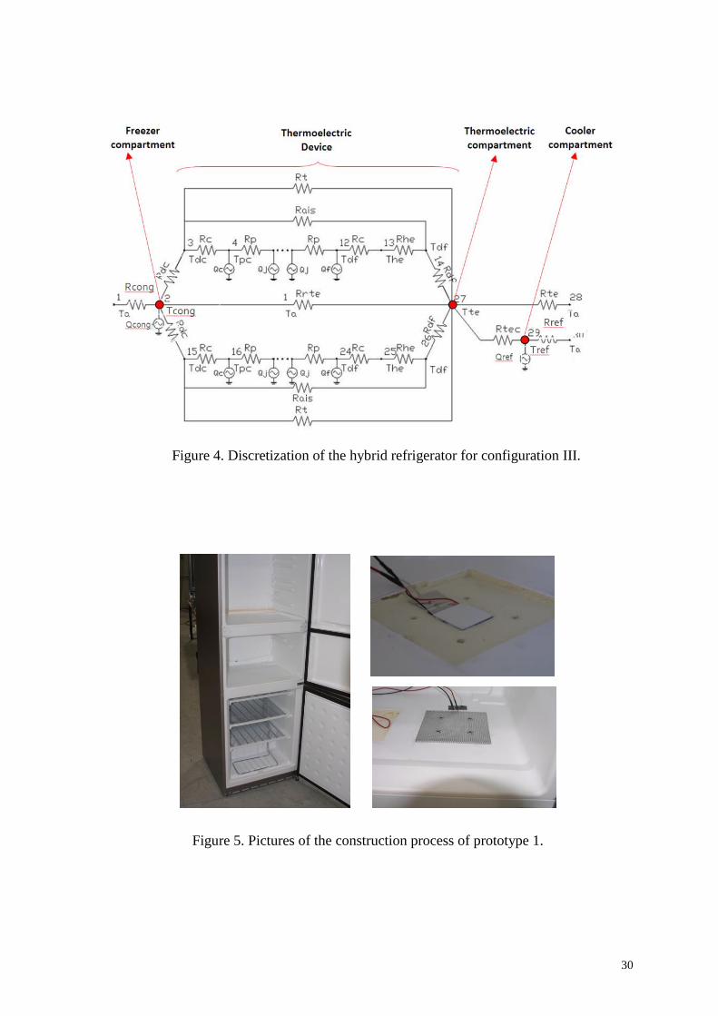
3.3. Configuration III
Following the idea of decreasing the temperature of the hot end of the Peltier
modules and therefore reduce the temperature difference between their ends, we designed
configuration III, characterized by the fact that the thermoelectric device was installed in
the wall between the freezer and thermoelectric compartments, as Figure 1 displays. In this
configuration, the heat from the hot side of the Peltier modules is emitted directly into the
freezer compartment, where is absorbed and given off to the environment, so that the
required power of the freezer compartment increases according to Eq. (4)
tec,pfreezh,pfreezfreez' WQQQQQ ++=+=
(4)
Therefore, configuration III is also a cascade refrigeration system with the great
advantage that the Peltier modules work in optimal conditions, since their hot ends are
connected to an environment at extremely low temperatures (below -22 ºC), thus
increasing the COP and reducing the electric power consumption of the thermoelectric
device.
4. DESIGN AND FURTHER IMPROVEMENT OF THE NEW HYBRID
REFRIGERATOR
In order to design and propose some improvements of the hybrid refrigerator, the
following methodology is conducted:
- Implementation of a computational model to simulate the whole hybrid refrigerator and
study of the influence of different parameters, such as number of Peltier modules installed,
position of the thermoelectric device, thermal resistances of the heat exchangers, thickness
of the walls, etc. This model is intended to determine the best option between
configurations I, II and III, and quantify the differences between them. The heat
10
exchangers at either side of the Peltier modules are studied with Computational Fluid
Dynamics software (CFD), in order to reduce their thermal resistance.
- Improvement of the hybrid refrigerator based on experimental tests conducted with
prototypes.
4.1. Computational model
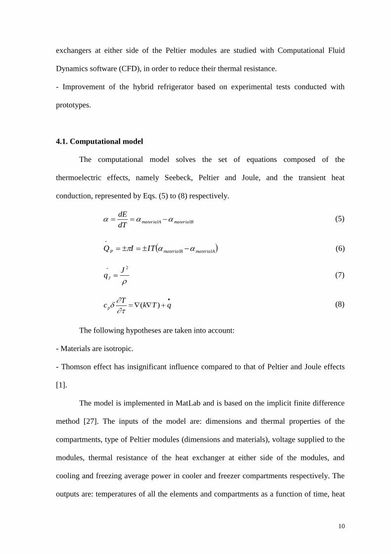
The computational model solves the set of equations composed of the
thermoelectric effects, namely Seebeck, Peltier and Joule, and the transient heat
conduction, represented by Eqs. (5) to (8) respectively.
materialBmaterialAdT
dE (5)
materialAmaterialBPTIIQ
(6)
2JqJ
(7)
qTkT
cp )(
(8)
The following hypotheses are taken into account:
- Materials are isotropic.
- Thomson effect has insignificant influence compared to that of Peltier and Joule effects
[1].
The model is implemented in MatLab and is based on the implicit finite difference
method [27]. The inputs of the model are: dimensions and thermal properties of the
compartments, type of Peltier modules (dimensions and materials), voltage supplied to the
modules, thermal resistance of the heat exchanger at either side of the modules, and
cooling and freezing average power in cooler and freezer compartments respectively. The
outputs are: temperatures of all the elements and compartments as a function of time, heat

11
flow rates, electric power consumption and COP of both the thermoelectric device and the
refrigerator.
The finite difference method requires the discretization of the system, which
consists in reducing the system into a set of representative nodes. Figures 2, 3 and 4
present the discretization of the hybrid refrigerator for configuration I, II and III
respectively. Every node has a thermal capacity provided by Eq. (9), and is connected to
the surrounding nodes by thermal resistances calculated with Eq. (10).
pcVC (9)
kS
LR (10)
The thermal resistances corresponding to the walls of the refrigerator, where both
heat transfer conduction and convection take place, can be calculated with Eq. (11), where
the heat transfer coefficient is obtained with Eq. (12).
USRwall
1 (11)
exthk
e
h
U11
1
int
(12)
The convection coefficient inside and outside every compartment (hint, hext) is
calculated with Eq. (13), which is an experimental expression of the convection coefficient
in a plane plate that considers laminar flow and dismisses the influence of the viscosity
dissipation [28].
5
,
2/13/1
105ReRe
50Pr6.0
RePr664.0
cx
LLNu
(13)
The thermal contact resistance between a common 40x40 mm2 Peltier module and
the cold extender yields 0.03 K/W [29].

12
The nodes representing the Peltier module also include heat absorption or
generation corresponding to Peltier and Joule effects, presented by Eqs. (6) and (7). As an
example, Eqs. from (14) and (17) present the energy balance corresponding to node 6 in
Figure 3, which represents a node of the Peltier modules, where 𝑄6̇ stands for a ninth of the
heat generated by Joule effect provided by Eq. (7), C6 is the thermal capacity of node 6
obtained with Eq. (9), R56 and R67 stand for the thermal resistances between nodes 5-6 and
6-7 respectively, obtained with expression (10). Finally, T6 and T7 represent the
temperatures of nodes 6 and 7 in the instant of time , whereas T’5, T’6 and T’7 represent
the temperatures of nodes 5, 6 and 7 in the instant of time +δ.
6
'
6
6
6
67
67
56
65 TTC
QR
TT
R
TT
(14)
666'
66
675667
7
56
5 11QT
CT
C
RRR
T
R
T
(15)
6
6
66
6
67566
7
676
5
566
1111Q
CTT
C
RRCT
RCT
RC
(16)
6
6
67
676
6
67566
5
566
11
111Q
CTT
RCT
RRCT
RC
(17)
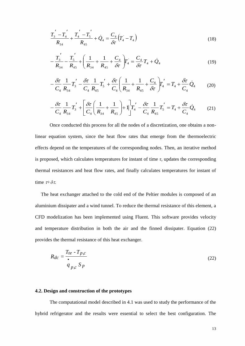
Likewise, Eqs. from (18) and (21) shows the energy balance for node 4 also in
Figure 3, which corresponds to the hot end of a Peltier module, where 𝑄4̇ represents a ninth
of the heat generated by Joule effect plus the heat absorbed by Peltier effect provided by
Eq. (6), C4 is the thermal capacity of node 4 obtained with Eq. (9), R34 y R45 stand for the
thermal resistances between nodes 3-4 and 4-5 respectively, obtained with expression (10).
Finally, T4 and T5 represent the temperatures of nodes 4 and 5 in the instant of time ,
whereas T’3, T’4 and T’5 represent the temperatures of nodes 3, 4 and 5 in the instant of
time +δ.
13
4
'
44
4
45
54
34
43 TTC
QR
TT
R
TT
(18)
444'
44
453445
5
34
3 11QT
CT
C
RRR
T
R
T
(19)
4
4
444
45344
5
454
3
344
1111Q
CTT
C
RRCT
RCT
RC
(20)
4
4
45
454
4
45344
3
344
11
111Q
CTT
RCT
RRCT
RC
(21)
Once conducted this process for all the nodes of a discretization, one obtains a non-
linear equation system, since the heat flow rates that emerge from the thermoelectric
effects depend on the temperatures of the corresponding nodes. Then, an iterative method
is proposed, which calculates temperatures for instant of time τ, updates the corresponding
thermal resistances and heat flow rates, and finally calculates temperatures for instant of
time +δ.
The heat exchanger attached to the cold end of the Peltier modules is composed of an
aluminium dissipater and a wind tunnel. To reduce the thermal resistance of this element, a
CFD modelization has been implemented using Fluent. This software provides velocity
and temperature distribution in both the air and the finned dissipater. Equation (22)
provides the thermal resistance of this heat exchanger.
pc,p
c,ptedc
Sq
TTR
•
-= (22)
4.2. Design and construction of the prototypes
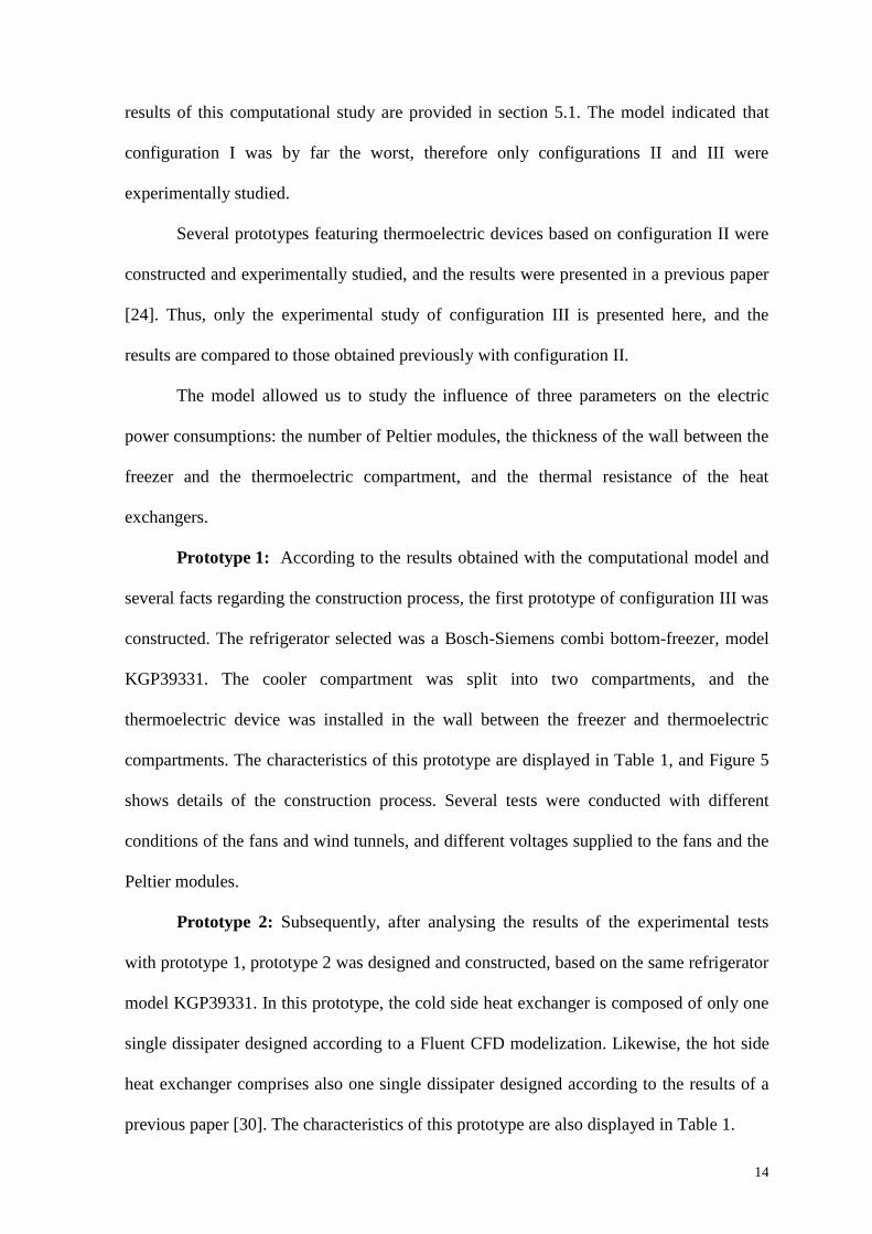
The computational model described in 4.1 was used to study the performance of the
hybrid refrigerator and the results were essential to select the best configuration. The
14
results of this computational study are provided in section 5.1. The model indicated that
configuration I was by far the worst, therefore only configurations II and III were
experimentally studied.
Several prototypes featuring thermoelectric devices based on configuration II were
constructed and experimentally studied, and the results were presented in a previous paper
[24]. Thus, only the experimental study of configuration III is presented here, and the
results are compared to those obtained previously with configuration II.
The model allowed us to study the influence of three parameters on the electric
power consumptions: the number of Peltier modules, the thickness of the wall between the
freezer and the thermoelectric compartment, and the thermal resistance of the heat
exchangers.
Prototype 1: According to the results obtained with the computational model and
several facts regarding the construction process, the first prototype of configuration III was
constructed. The refrigerator selected was a Bosch-Siemens combi bottom-freezer, model
KGP39331. The cooler compartment was split into two compartments, and the
thermoelectric device was installed in the wall between the freezer and thermoelectric
compartments. The characteristics of this prototype are displayed in Table 1, and Figure 5
shows details of the construction process. Several tests were conducted with different
conditions of the fans and wind tunnels, and different voltages supplied to the fans and the
Peltier modules.
Prototype 2: Subsequently, after analysing the results of the experimental tests
with prototype 1, prototype 2 was designed and constructed, based on the same refrigerator
model KGP39331. In this prototype, the cold side heat exchanger is composed of only one
single dissipater designed according to a Fluent CFD modelization. Likewise, the hot side
heat exchanger comprises also one single dissipater designed according to the results of a
previous paper [30]. The characteristics of this prototype are also displayed in Table 1.

15
5. RESULTS AND ANALYSIS
5.1. Computational model results
The accuracy of the model was determined by comparing simulated and
experimental results obtained during the testing process of prototype 1. Figures 6 and 7
show experimental and simulated temperatures for the case when the fan over the hot side
dissipater was supplied with 3.6 V (minimum voltage needed to make the fan rotate).
Figure 6 presents the performance of the hybrid refrigerator when the Peltier modules are
not supplied whereas Figure 7 shows the case when the voltage supplied to each module is
2 V. These figures prove that the computational model predicts accurately the temperatures
of all the compartments.
One fact to bear in mind is that the simulated temperatures do not follow cyclical
patterns, since the model predicts effective values. In fact, the effective cooling and
freezing powers are inputs of the model, which can be obtained with Eq. (23).
Effective power (W) = Compressor power (W) x on/off relationship (0/1) (23)
It is a real fact that the compressor follows an on/off pattern. Thus, once the
refrigerator is switched on, the compressor works until the lower set temperature is
reached. Then, it stops and the temperature rises again, so that a cyclical pattern arises. The
computational model does not include this effect, but it supposes that the compressor
always works at effective power.
The first computational study set out to compare the performance of configuration I
and II, and quantify the differences. Procedures and electric power consumptions were
published in a previous paper [24] and are summarized in Table 2, along with the results of
configuration III provided by the computational model for similar working conditions,
which were: ambient temperature 25 ºC, cooler compartment temperature 5 ºC, freezer
compartment temperature -22 ºC, and thermoelectric compartment temperature 0 ºC. Table
2 points out that configuration I is by far the worst, whereas configuration III is the most

16
efficient. These results confirm the predictions raised in section 3 regarding the influence
of the temperature difference between the ends of the modules on the COP of the
thermoelectric device, represented by Eq. (2), which explains the significantly higher
electric power consumption of the thermoelectric device in configuration I (about 100 W)
with respect to that of configuration III (1.1 W), for similar working conditions.
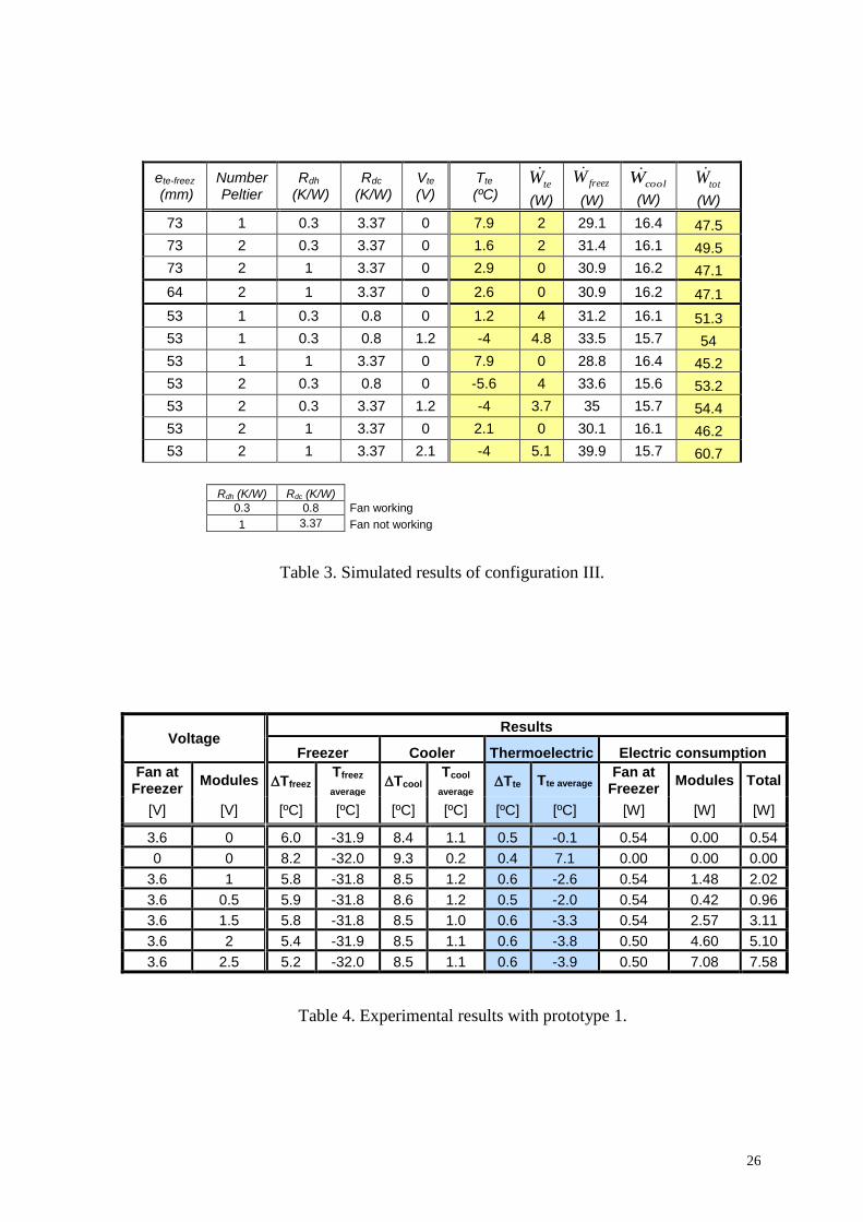
Then, once configuration III was proved to provide the best results regarding
electric power consumption, the computational model was used again to determine the
optimum values of the input variables that allow us to attain the desired constant
temperature in the thermoelectric compartment, with minimum electric power
consumption. Table 3 summarizes the simulated results for configuration III of the hybrid
refrigerator, where one can see that the study variables are the thickness of the wall
between thermoelectric and freezer compartments, thermal resistances of the heat
exchangers and number of Peltier modules, whereas the constant parameters are the
temperatures of the cooler compartment (5 ºC), freezer compartment (-22 ºC) and
environment (25 ºC).
From Table 3, one can conclude that the best results are obtained when using a 53
mm thick wall between the thermoelectric and freezer compartments, which offers a
twofold benefit: less insulating material is needed and more space is available inside the
thermoelectric compartment.
It is also concluded that one single Peltier module is capable of providing -4 ºC in
the thermoelectric compartment. However, two Peltier modules are decided to be installed
in the prototypes for two main reasons: First of all, two Peltier modules provide higher
cooling power than one single module, which might be useful when a big hot mass is
placed inside this compartment. Secondly, given a constant cooling power in the
thermoelectric compartment, the electric power consumption of one single module is
higher than the electric power consumption of two Peltier modules. This seemingly

17
contradictory fact occurs owing to the fact that the COP of a Peltier module increases as
the electric power supplied to it decreases, since the electric current also decreases and, in
turn, the heat generated by Joule effect, as Eq. (7) indicates.
The CFD model was used to study different configurations of the dissipater attached
to the cold end of the Peltier modules. The selected configuration of the cold heat
exchanger for prototype 2 has top air inflow, 1.5x18 mm2 fins spaced 11 mm, and wider
inflow surface.
5.2. Experimental results
Table 4 shows experimental temperatures and electric power consumptions of
prototype 1 in steady state, for ambient temperature 20 ºC, temperature of the freezer
compartment -30 ºC and temperature of the cooler compartment 2 ºC. It must be
highlighted that the thermoelectric compartment reaches 0 ºC with extra electric power
consumption of 0.5 W, which comprises only the consumption of the fan, since the Peltier
modules do not need to be supplied. Likewise, the thermoelectric compartment reaches -4
ºC with an extra electric power consumption of 7.6 W, which comprises the consumption
of the fan (0.5 W) and the Peltier modules (7.1 W). Furthermore, one can observe that the
temperature of the thermoelectric compartment keeps virtually constant (even though no
extra temperature control system is installed) oscillating 0.6 ºC at most. In contrast,
temperatures at freezer and cooler compartments oscillate up to 9.3 ºC, as can be seen in
Figures 6, 7 and 8. Moreover, the temperature in the thermoelectric compartment is easily
controlled since one can modify both the voltage supplied to the modules and the voltage
supplied to the fan.
Figure 8 shows temperatures at steady state of prototype 1, with 3.6 V supplied to
the fan and 2.5 V supplied to the modules, which leads to 7.6 W of electric power

18
consumption. It can be observed that the temperature difference between the cold end of
the modules and the thermoelectric compartment (Tc) is far larger than the temperature
difference between the hot end of the modules and the freezer compartment (Th) which
leads to the conclusion that the thermal resistance of the heat exchanger at the cold side is
too high. This is no surprise since the heat exchanger at the cold side comprises only
dissipaters whereas the heat exchanger at the hot side is composed of dissipaters, wind
tunnels and fans.
In order to solve this problem, we installed a fan (no wind tunnel) inside the
thermoelectric compartment to force the air to flow through the fins of the dissipater and
enhance the heat transfer. Results for this small improvement of prototype 1 are shown in
Table 5, where one can see the average temperatures and electric power consumptions for
different working conditions of the refrigerator at constant ambient temperature of 25 ºC.
Results from Table 5 point out that the use of a fan in the thermoelectric compartment is
highly beneficial. Specifically, the thermoelectric compartment reaches -4 ºC with 5.7 W
of electric power consumption, for 25 ºC of ambient temperature, whereas in the previous
case (when no fan was installed at the cold side) the thermoelectric compartment reached -
4 ºC with 7.5 W of electric consumption, even though the ambient temperature was 20 ºC.
One can also realize that the temperature in the freezer compartment has strong
influence on the electric power consumption of the modules. For instance, for electric
power consumption of 5.5 W, the temperature in the thermoelectric compartment reaches -
4 ºC if the temperature in the freezer compartment is -29 ºC. However, the temperature in
the thermoelectric compartment reaches -3 ºC if the temperature in the freezer
compartment is -24 ºC. The reason why this occurs is that, as the temperature at the freezer
compartment decreases, the temperature difference between the ends of the modules also
decreases, which leads to an increase in the COP of the modules.

19
These experimental results, along with CFD simulations for the dissipater and the
wind tunnel in the thermoelectric compartment, led to the construction of a new prototype
of hybrid refrigerator for configuration III, called prototype 2, shown in Figure 9. Table 6
shows that the temperature in the thermoelectric compartment of this prototype 2 keeps
constant at 0.4 ºC, oscillating ±0.2 ºC at most, with 1.1 W of electric power consumption
of the thermoelectric device, for ambient temperature 25 ºC, temperature in the cooler
compartment set at 5 ºC and temperature in the freezer compartment set at -22 ºC. This
electric power consumption includes only the fans, since there is no need to supply the
modules. The electric power consumption of the hybrid refrigerator was 46.3 W (1.11
kWh/day). Likewise, for the same temperature conditions, the temperature in the
thermoelectric compartment was -4.1 ºC, with 1.8 W of electric power consumption of the
thermoelectric device, and 49.2 W (1.18 kWh/day) of electric power consumption of the
hybrid refrigerator.
These facts embody the significant improvement achieved with prototype 2.
Specifically, the electric power consumption of the thermoelectric device decreases with
respect to that attained previously with prototypes of configuration II [24] from 4.9 to 1.1
W, which leads to a reduction by about 8 % of the electric power consumption of the
hybrid refrigerator. This means that this refrigerator can be included in energy efficiency
class A, according European rules and regulations [31].
This technology presents a huge potential since the quality of food conservation
increases via improving the temperature control system, with competitive values of electric
power consumption. What is more, the thermoelectric device is also an efficient system to
remove the ice built up in the dissipater of the thermoelectric compartment. In fact, if the
voltage supplied to the Peltier modules is reversed, the thermoelectric device works as a
heat pump and, therefore, the dissipater warms up and the ice melts.

20
6. CONCLUSIONS
This paper presents a hybrid refrigerator that combines thermoelectrics and vapour
compression technology, which has an extra compartment whose temperature can be
adjusted at any value between 0 and -4 ºC, oscillating 0.4 ºC at most. This new
compartment is controlled by a thermoelectric device that provides high quality
temperature control, and eliminates the cyclical behaviour of devices refrigerated by
vapour compression systems, which is beneficial to the conservation of food.
The design and optimization of this hybrid refrigerator were based on a
computational model designed for this application. The final design of the thermoelectric
device comprises two Peltier modules and one dissipater at either end of the modules,
endowed with a fan and a wind tunnel. Among all configurations studied, model
simulations suggest that the thermoelectric device must be installed in the wall between the
thermoelectric and the freezer compartments, so that the heat generated at the hot end of
the modules is given off into the freezer compartment, that is, configuration III.
Experimental results with the improved prototype of configuration III indicate that
the temperature in the thermoelectric compartment keeps constant at 0 ºC and oscillates 0.4
ºC at most, with 1.1 W of electric power consumption of the thermoelectric device, for
ambient temperature 25 ºC, temperature in the cooler compartment 5 ºC and temperature in
the freezer compartment -22 ºC. In these conditions, the electric power consumption of the
refrigerator is 46.3 W (1.11 kWh/day). Likewise, for the same temperature conditions, the
temperature in the thermoelectric compartment is -4.1 ºC, with 1.8 W of electric power
consumption of the thermoelectric device, and 49.2 W (1.18 kWh/day) of electric power
consumption of the refrigerator. These results indicate that the electric power consumption
of the best prototype of configuration III is 10 % lower than that attained with the best
prototype of configuration II, which emits the heat generated at the hot side of the Peltier
modules to the cooling compartment.

21
These facts prove that the combination of vapour compression and thermoelectrics
is an attractive alternative to current domestic refrigerators, given the competitive values of
electric power consumption of hybrid refrigerators. Specifically, the hybrid refrigerator
presented in this paper is included in energy efficiency class A, according European rules
and regulations.
ACKNOWLEDGEMENTS
The authors are indebted to Bosch-Siemens enterprise for the economic support to this
work, whose results are been protected under patent [26].
REFERENCES
[1] D.M. Rowe, Thermoelectrics handbook macro to nano, first ed., CRC Press, Boca
Raton, FL, 2006.
[2] A.F. Ioffe, Semiconductor thermoelements and thermoelectric cooling, Infosearch,
London, UK, 1957.
[3] M.S. Crouthamel, J.F. Panas, B. Shelpuk, Nine ton thermoelectric air-conditioning
system, ASHRAE Tran. 70 (1964) 139-148.
[4] D. Jones, B. Mathiprakasam, P. Heenan, D. Brantley, Development of 1000 W
thermoelectric air-conditioner, 13th International Conference on Thermoelectric
Energy Conversion, Nancy, France, 1989, pp. 232-234.
[5] Marlow Industries, www.marlow.com, 2011.
[6] Global Medical Instrumentation, www.gmi-inc.com, 2011.
[7] J.G. Vián, D. Astrain, M. Domínguez, Numerical modelling and design of a
thermoelectric dehumidifier. Appl. Therm. Eng. 22 (2002) 407-422.
[8] L.E. Bell, Cooling, heating, generating power, and recovering waste heat with
thermoelectric systems, Science 321 (2008) 1457-1461.
22
[9] G. Min, D.M. Rowe, Experimental evaluation of prototype thermoelectric domestic-
refrigerators, Appl. Energ. 83 (2006) 133-152.
[10] G. Min, D.M. Rowe, Cooling performance of integrated thermoelectric microcooler,
Solid State Electron. 43 (1999) 923-929.
[11] J.M. Gordon, K.C. Ng, H.T. Chua, A. Chakraborty, The electro-adsorption chiller: a
miniaturized cooling cycle with applications to micro-electronics, Int. J. Refrig. 25
(2002) 1025-1033.
[12] S.B. Riffat, M.A. Xiaoli, R. Wilson, Performance simulation and experimental testing
of a novel thermoelectric heat pump system, Appl. Therm. Eng. 26 (2006) 494-501.
[13] Y. Chang, C. Chang, M. Ke, S. Chen, Thermoelectric air-cooling module for
electronic devices, Appl. Therm. Eng. 29 (2009) 2731-2737.
[14] R. Chein, G. Huang, Thermoelectric cooler application in electronic cooling, Appl.
Therm. Eng. 24 (2004) 2207-2217.
[15] H. Mao-Gang, L. Tie-Chen, L. Zhi-Gang, Z. Ying, Testing of the mixing refrigerants
HFC152a/HFC125 in a domestic refrigerator, Appl. Therm. Eng. 25 (2005) 1169-
1181.
[16] D. Reid, Food preservation, ASHRAE J. 41 (1999) 40-45.
[17] L. Buzelin, S. Amico, J. Vargas, J. Parise, Experimental development of an intelligent
refrigeration system, Int. J. Refrig. 28 (2005) 165-175.
[18] D.Y. Liu, W.R. Chang, J.Y. Lin, Performance comparison with effect of door opening
on variable and fixed frequency refrigerators/freezers, Appl. Therm. Eng. 24 (2004)
2281-2292.
[19] Z. Lu, G. Ding, Temperature and time-sharing running combination control strategy
of two-circuit cycle refrigerator freezer with parallel evaporators, Appl. Therm. Eng.
26 (2006) 1208-1217.
[20] A. Leva, L. Piroddi, M. Di Felice, A. Boer, R. Paganini, Adaptive relay-based control
of household freezers with on-off actuators, Control Eng. Pract. 18 (2010) 94-102.

23
[21] P. Mithraratne, N.E. Wijeysundera, An experimental and numerical study of hunting
in thermostatic-expansion-valve-controlled evaporators, Int. J. Refrig. 25 (2002) 992-
998.
[22] V. Mulay, A. Kulkarni, D. Agonafer, R. Schmidt, Effect of the location and the
properties of thermostatic expansion valve sensor bulb on the stability of a
refrigeration system, J. Heat Transf. 127 (2005) 85-94.
[23] J.G. Vián, D. Astrain, Development of a thermoelectric refrigerator with two-phase
thermosyphons and capillary lift. Appl. Therm. Eng. 29 (2009) 1935-1940.
[24] J.G. Vián, D. Astrain, Development of a hybrid refrigerator combining
thermoelectricity and vapour-compression technologies. Appl. Therm. Eng. 29 (2009)
3319-3327.
[25] D. Astrain, J.G. Vián, M. Domínguez, Increase of COP in the thermoelectric
refrigeration by the optimisation of heat dissipation, Appl. Therm. Eng. 23 (2003)
2183-2200.
[26] D. Astrain, J.G. Vián, J. Calvillo, J. Alemán, S. García, Refrigerator device and
process in order to keep constant the inner temperature in a compartment of a domestic
refrigerator, FEK / Petitioner: BSH ELECTRODOMESTICOS ESPAÑA, S.A.
Applications number: P200701914 / Application date: 29/06/2007 NumZTG:
2007P01673ES.
[27] M.N. Ozisik, Finite difference methods in heat transfer, first ed., CRC Press Boca
Raton, FL, 1994.
[28] G.V. Parmelee, R.G. Huebscher, Heat transfer by forced convection along a smooth
flat surface, Heat Piping Air. Cond. 19 (1947) 115-130.
[29] T.M. Ritzer, P.G. Lau, Economic optimization of heat sink, 13th International
Conference on Thermoelectrics, Kansas City, Missouri, USA, 1994, pp. 177-180.
[30] D. Astrain, J.G. Vián, Study and optimization of the heat dissipater of a thermoelectric
refrigerator, J. Enhanc. Heat Transf. 12 (2005) 159-170.
[31] UNE-EN 153 2006 and 94/2/CE.

24
FIGURE CAPTIONS Figure 1. Configurations of the thermoelectric device in the hybrid refrigerator.
Figure 2. Discretization of the hybrid refrigerator for configuration I.
Figure 3. Discretization of the hybrid refrigerator for configuration II.
Figure 4. Discretization of the hybrid refrigerator for configuration III.
Figure 5. Pictures of the construction process of prototype 1.
Figure 6. Simulated and experimental temperatures of prototype 1, with no voltage
supplied to the Peltier modules.
Figure 7. Simulated and experimental temperatures of prototype 1, with 2 V supplied to
either Peltier module.
Figure 8. Experimental temperatures of prototype 1, with 2.5 V supplied to the Peltier
modules.
Figure 9. Front picture of prototype 2.

25
TABLES
Prototype 1 Prototype 2
Volume freezer compartment 84x10-3 m3 84x10-3 m3
Volume cooler compartment 184x10-3 m3 184x10-3 m3
Volume thermoelectric compartment 71x10-3 m3 71x10-3 m3
Number of Peltier modules 2 Marlow DT12-6L 2 Marlow DT12-6L
Cold side heat exchanger Two 120x120x12 mm3
dissipaters
One 150x180x12 mm3
dissipater, with
fins separated 11 mm
One fan SUNON
KDE1212PTB1-6A
Hot side heat exchanger
Two 120x120x12 mm3
dissipaters, with fins
separated 5.5 mm
Two fans SUNON
KDE1212PTB1-6A
One 150x180x12 mm3
dissipater with fins
separated 5.5 mm
One fan SUNON
KDE1212PTB1-6A
Table 1. Characteristics of the prototypes of configuration III.
Configuration I Configuration II Configuration III
freezW [W] 25.2 25.3 30.6
coolW [W] 13.8 19.7 13.5
teW [W] 99.6 4.9 1.1
totW [W] 138.6 49.9 45.2
Energy efficiency class No classifiable B A
Table 2. Simulated electric power consumption for configurations I, II and III.
26
ete-freez
(mm) Number Peltier
Rdh (K/W)
Rdc (K/W)
Vte (V)
Tte
(ºC) teW
(W)
freezW
(W)
coolW
(W)
totW
(W)
73 1 0.3 3.37 0 7.9 2 29.1 16.4 47.5
73 2 0.3 3.37 0 1.6 2 31.4 16.1 49.5
73 2 1 3.37 0 2.9 0 30.9 16.2 47.1
64 2 1 3.37 0 2.6 0 30.9 16.2 47.1
53 1 0.3 0.8 0 1.2 4 31.2 16.1 51.3
53 1 0.3 0.8 1.2 -4 4.8 33.5 15.7 54
53 1 1 3.37 0 7.9 0 28.8 16.4 45.2
53 2 0.3 0.8 0 -5.6 4 33.6 15.6 53.2
53 2 0.3 3.37 1.2 -4 3.7 35 15.7 54.4
53 2 1 3.37 0 2.1 0 30.1 16.1 46.2
53 2 1 3.37 2.1 -4 5.1 39.9 15.7 60.7
Rdh (K/W) Rdc (K/W)
0.3 0.8 Fan working
1 3.37 Fan not working
Table 3. Simulated results of configuration III.
Voltage Results
Freezer Cooler Thermoelectric Electric consumption
Fan at Freezer
Modules TfreezTfreez
average Tcool
Tcool
average Tte Tte average
Fan at Freezer
Modules Total
[V] [V] [ºC] [ºC] [ºC] [ºC] [ºC] [ºC] [W] [W] [W]
3.6 0 6.0 -31.9 8.4 1.1 0.5 -0.1 0.54 0.00 0.54
0 0 8.2 -32.0 9.3 0.2 0.4 7.1 0.00 0.00 0.00
3.6 1 5.8 -31.8 8.5 1.2 0.6 -2.6 0.54 1.48 2.02
3.6 0.5 5.9 -31.8 8.6 1.2 0.5 -2.0 0.54 0.42 0.96
3.6 1.5 5.8 -31.8 8.5 1.0 0.6 -3.3 0.54 2.57 3.11
3.6 2 5.4 -31.9 8.5 1.1 0.6 -3.8 0.50 4.60 5.10
3.6 2.5 5.2 -32.0 8.5 1.1 0.6 -3.9 0.50 7.08 7.58
Table 4. Experimental results with prototype 1.

27
Freezer Cooler Thermoelectric Electric consumption [W]
Vte Ta Tfreez Tcool Tfreez
averageTfreez
Tcool
averageTcool
Tte
average Tte Fan Fan
Modules Total
[V] [ºC] [ºC] [ºC] [ºC] [ºC] [ºC] [ºC] [ºC] [ºC] Freezer Cooler
0 25 -22 6 -28.5 7.6 5 4.7 3.1 0.5 0.8 0.0 0.0 0.8
1 25 -22 6 -28.3 7.4 4.9 4 1.4 0.5 0.8 0.0 1.2 2.0
2 25 -22 6 -28.1 7.5 5 6.1 0.1 0.4 0.8 0.0 4.4 5.2
0 25 -22 6 -30.8 5.6 4.9 6.5 -1.3 0.8 0.8 0.3 0.0 1.1
1 25 -22 6 -30.7 5.4 4.9 4.2 -3.1 0.7 0.8 0.3 1.4 2.5
2 25 -22 6 -28 7.3 4.8 3.7 -4.6 1 0.8 0.3 4.6 5.7
0 25 -26 6 -29.6 4.5 5 4 -2.5 9 1.8 0.3 0.0 2.1
2 25 -26 6 -29.9 0.4 4.9 3.6 -7.5 0.7 1.7 0.3 4.6 6.7
0 25 -18 6 -23.8 9.2 5 5.8 0.9 0.7 0.8 0.3 0.0 1.1
1 25 -18 6 -23.8 9 4.9 3.7 -1.6 0.9 0.8 0.3 1.2 2.3
2 25 -18 6 -23.8 9.2 4.9 5.1 -3 1 0.8 0.3 4.4 5.5
Table 5. Experimental results of prototype 1 (ambient temperature 25 ºC).
Freezer Cooler Thermoelectric Electric consumption [W]
Vte Ta Tfreez Tcool Tfreez
averageTfreez
Tcool
averageTcool
Tte
average Tte Fan Fan
Modules Total
[V] [ºC] [ºC] [ºC] [ºC] [ºC] [ºC] [ºC] [ºC] [ºC] Freezer Cooler
0 25 -22 5 -28.8 9 7.1 6 0.4 0.4 0.93 0.18 0 46.3
0.55 25 -22 5 -28.7 9 7.4 6 -4.1 0.4 1 0.42 0.4 49.2
0 25 -18 5 -25.1 10 7.3 6 -0.2 0.4 1 0.53 0 42.5
Table 6. Experimental results of prototype 2.

28
FIGURES
Figure 1. Configurations of the thermoelectric device in the hybrid refrigerator.
Thermoelectric device
Configuration I
Thermoelectric
compartment
Cooler compartment
Vapour compression
Freezer compartment
Vapour compression
Configuration II
Thermoelectric
compartment
Cooler compartment Vapour compression
Freezer compartment
Vapour compression
Configuration III
Thermoelectric
compartment
Cooler compartment Vapour compression
Freezer compartment
Vapour compression
Heat Exchanger
Heat Exc. r
Fan
Peltier modules
Cold Extender
Insulation

29
Figure 2. Discretization of the hybrid refrigerator for configuration I.
Figure 3. Discretization of the hybrid refrigerator for configuration II.
30
Figure 4. Discretization of the hybrid refrigerator for configuration III.
Figure 5. Pictures of the construction process of prototype 1.

31
Figure 6. Simulated and experimental temperatures of prototype 1, with no voltage
supplied to the Peltier modules.
Figure 7. Simulated and experimental temperatures of prototype 1, with 2 V supplied
to either Peltier module.
-40
-35
-30
-25
-20
-15
-10
-5
0
5
10
0 100 200 300 400 500 600 700 800 900
Time [min]
Tem
pera
ture
[ºC
]
T freez, model
Tte, exp T cool,exp
Tte, model T cool,model
T freez, exp
T freedfgdgz, model
-40,0
-30,0
-20,0
-10,0
0,0
10,0
20,0
30,0
0 100 200 300 400 500 600 700 800 900 1000
Time [min]
Tem
pera
ture
[ºC
]
Tte,exp
T cool,exp
Tte,model
T cool,model
Tp,c, exp Tp,c, model
Tp,h, model Tp,h, exp
T freez, exp
T freez, exp

32
Figure 8. Experimental temperatures of prototype 1, with 2.5 V supplied to the Peltier
modules.
Figure 9. Front picture of prototype 2.
-40
-35
-30
-25
-20
-15
-10
-5
0
5
10
200 220 240 260 280 300 320 340 360 380 400 420 440 460 480 500 520 540 560 580 600
Time [min]
Tem
pera
ture
[ºC
]
∆Tc
∆Th
Tfreez
Tte
Tcext
Tcool
Tp,c
Tp,h