improvement of reciprocating engine power plants
TRANSCRIPT

Ville Manninen
IMPROVEMENT OF RECIPROCATING ENGINE POWER PLANTS
COMPETITIVENESS AND MITIGATION OF TECHNOLOGY RISK
BETWEEN GAS TURBINE POWER PLANTS BY MEANS OF PROD-
UCT SAFETY.
Opinnäytetyö
CENTRIA-AMMATTIKORKEAKOULU
Teknologiaosaamisen johtamisen koulutusohjelma
Toukokuu 2017
TIIVISTELMÄ OPINNÄYTETYÖSTÄ
Yksikkö
Kokkola
Aika
Toukokuu 2017
Tekijä
Ville Manninen
Koulutusohjelma
Teknologiaosaamisen johtamisen koulutusohjelma
Työn nimi
MÄNTÄMOOTTORIVOIMALAITOSTEN KILPAILUKYVYN PARANTAMINEN JA
TEKNOLOGIARISKIN PIENENTÄMINEN KAASUTURBIINIEN VÄLILLÄ
TUOTETURVALLISUUDEN KEINOIN.
Työn ohjaaja
Marko Forsell
Sivumäärä
79+5
Työelämäohjaaja
Niklas Wägar, Sari Kojo
Työssä tutkittiin, kuinka mäntämoottorivoimalaitosten kilpailukykyä voidaan parantaa kaasuturbiinien
hallitsemalla markkina-alueella Yhdysvalloissa tuoteturvallisuuden keinoin. Lisäksi tavoitteena oli
pienentää asiakkaiden mieltämää teknologiariskiä mäntämoottorivoimalaitoksia kohtaan. Työ tehtiin
Wärtsilälle ja rajattiin Wärtsilän Smart Power Generation –voimalatioksiin, joiden pääasiallisia
kilpailijoita ovat kaasuturbiini valmistajat.
Teoriaosuudessa tutustuttiin kaasuturbiini- ja mäntämoottorivoimalaitosten teknologiaan. Lisäksi
käytiin läpi näiden historiassa tapahtuneita onnettomuuksia, tutkittavan markkina-alueen
ominaisuuksia, vallitseva lainsäädäntö ja standardeja tuoteturvallisuuden puolella sekä yleisesti
kilpailukykyyn liittyvää teoriaa.
Tutkimus toteutettiin kyselytutkimuksena, johon kohdehenkilöiksi valittiin henkilöitä organisaation eri
osa-alueilta. Yhteistä kohdehenkilöille oli, että he ovat työskennelleet alalla pitkään ja olleet läheisessä
yhteistyössä asiakkaiden kanssa. Myös kokemus molemmista teknologioista on ollut toivottavaa
henkilöitä valittaessa.
Tutkimustulos osoitti, että sisäisiä toimintatapoja muuttamalla ja eri elinkaaren vaiheisiin, kuten
markkinointiin ja myyntiin, tietotaitoa lisäämällä voidaan lisätä kilpailukykyä ja osittain pienetää
teknologiariskiä. Osittainen teknologiariskin pienentäminen johtuu siitä, että tutkimustuloksien
perusteella teknologiariski on myös muuta kuin tuoteturvallisuuteen liittyviä asioita, joita ei voida
perustella turvallisuuden hallinnalla.
Sivumäärä: 79+5
Asiasanat
Kilpailukyky, Energia, Kaasuturbiini, HSE, Voimalaitos, Tuotevastuu, Tuoteturvallisuus,
Mäntämoottori, Riskienhallinta, Turvallisuus, Smart Power Generation, Teknologia riski

CENTRIA UNIVERSITY OF AP-
PLIED SCIENCES
Kokkola
Date
May 2017 Author
Ville Manninen
Degree programme
Technology Management
Name of research
IMPROVEMENT OF RECIPROCATING ENGINE POWER PLANTS COMPETITIVENESS AND
MITIGATION OF TECHNOLOGY RISK BETWEEN GAS TURBINE POWER PLANTS BY
MEANS OF PRODUCT SAFETY.
Instructor
Marko Forsell Pages
79+5
Supervisor
Niklas Wägar, Sari Kojo
The aim of the study was to investigate how competitiveness could be improved in gas turbine driven
markets in United States, and to mitigate customer seen technology risk for reciprocating engine power
plants by means of product safety. Main market area in this research was United States. Research scope
was limited to Wärtsilä Smart Power Generation -power plants, which main competitors are gas turbine
companies.
Theoretical part of the thesis examines background of both technologies. This includes gas turbines and
reciprocating engine technologies, and their accidents back in history, exploration of United States mar-
ket, local legislation and guiding standards from product safety as well as general information related
to competitiveness.
The research was done by survey and by interviewing selected persons from different areas of the or-
ganisation. Selected persons have been working long time in the industry and have been in close oper-
ation with customers. Also, selected persons should have had experience both from gas turbines and
reciprocating engine power plants.
Results showed that with changing internal communication and way of working, and adding compe-
tence of product safety awareness in areas like sales and marketing, competitiveness can be increased
and the technology risk can be decreased. Based on the results, technology risk is more than just product
safety, and for that reason cannot be fully mitigated.
Pages: 79+5
Key words
Competitiveness, Energy, Gas turbine, HSE, Power plant, Product liability, Product safety, Reciprocat-
ing engine, Risk management, Safety, Smart Power Generation, Technology risk

ABBREVATIONS
ALARP As Low As Reasonable Practical
ANSI American National Standard Institute
ASME American Society of Mechanical Engineers
BSC Balance Score Card
CAISO California Independent System Operator
CCGT Combined Cycle Gas Turbine
CFR Cleaning Force Ratio
CGR Compact Gas Ramp
CHP Combined Heat and Power
DC Direct Current
DIN Deutsches Institut für Normung
EEQ Engineering
EPC Engineering, Procurement, Construction
F(E)RA Fire (and explosion) Risk Assessment
FERC Federal Energy Regulatory Commission
FTA Fault Tree Analysis
GT Gas Turbine
HAZID Hazard identification
HAZOP Hazard and operability study
HSSE Health Safety Security Environment
HSSE Health, Safety, Security Environment
HV High Voltage
IPP Independent Power Producer
IRENA International Energy Agency
ISO Independent System Operator
ISO International Standardisation Organisation
KPI Key Performance Indicator
LEL Lower Explosion Limit
LNG Liquefied Natural Gas
LOPA Layer of Protection Analysis
LV Low voltage

MISO Minnesota Independent System Operator
MV Medium Voltage
NFPA National Fire Protection Agency
NFPA National Fire Protection Association
NOx Nitrogen Oxides
OHSAS Occupational Health and Safety Association
PFD Probability of failure on demand
PFHd Probability of dangerous failure per hour
QRA Quantitative Risk Assessment
RCA Root Cause Analysis
RTO Regional Transmission Organization
SCR Selective Catalytic Reduction
SIF Safety Instrumented Function
SIL Safety Integrity Level
SIS Safety Instrumented System
SPG Smart Power Generation
TSO Transmission System Operator

TIIVISTELMÄ
ABSTRACT
ABBREVIATIONS
TABLE OF CONTENT
ABBREVATIONS ................................................................................................................................... 2
1 INTRODUCTION ................................................................................................................................ 1
2 IMPROVEMENT OF COMPETITIVENESS .................................................................................. 3 2.1 Marketing........................................................................................................................................ 3
2.2 Management importance and resources ...................................................................................... 5
2.3 Differentiation ................................................................................................................................ 6
2.4 Balanced scorecard and key performance indicators ................................................................. 6
2.5 Energy markets in the United States of America ........................................................................ 8
2.5.1 Wärtsilä market position in the United States of America ............................................ 11
2.5.2 Products in liability law in the United States of America............................................... 13
2.5.3 Market argumentation and lobbying ............................................................................... 17
3 SAFETY IN POWER PLANTS ....................................................................................................... 19
3.1 Health, Safety, Security and Environment ................................................................................ 20
3.2 Product safety ............................................................................................................................... 21
3.3 Accidents in history of energy industry ..................................................................................... 24
3.4 Legislation and codes ................................................................................................................... 27
4 DIFFERENCES BETWEEN POWER PLANT TYPES ................................................................ 31
4.1 Common risks in both power plant types .................................................................................. 32
4.2 Turbine power plants ................................................................................................................... 32
4.3 Safety in gas and steam turbine power plants ........................................................................... 34
4.4 Components .................................................................................................................................. 36
4.4.1 Gas turbine ......................................................................................................................... 37 4.4.2 Compressors ....................................................................................................................... 38 4.4.3 Waste heat boiler ................................................................................................................ 38 4.4.4 Steam turbine ..................................................................................................................... 40
4.4.5 Generators .......................................................................................................................... 41 4.4.6 Electrical equipment .......................................................................................................... 41 4.4.7 Control and control equipment......................................................................................... 41 4.4.8 Other components .............................................................................................................. 43
4.5 Reciprocating engine power plants ............................................................................................. 44
4.6 Safety in reciprocating engine power plants .............................................................................. 45
4.7 Components .................................................................................................................................. 46
4.7.1 Reciprocating engine .......................................................................................................... 46 4.7.2 Generator ............................................................................................................................ 47 4.7.3 Fuel handling system.......................................................................................................... 47 4.7.4 Compressed air system ...................................................................................................... 47 4.7.5 Lubrication system ............................................................................................................. 48 4.7.6 Cooling water system ......................................................................................................... 48

4.7.7 Electrical equipment .......................................................................................................... 48
4.7.8 Control equipment ............................................................................................................. 49 4.7.9 Other systems and components ......................................................................................... 50
5 RESEARCH PLAN, QUESTIONS, TARGET AND METHODS ................................................ 51 5.1 Research Plan ............................................................................................................................... 51
5.2 Research question and target ...................................................................................................... 52
5.3 Literature ...................................................................................................................................... 52
5.4 Survey ............................................................................................................................................ 54
5.5 Business Cases .............................................................................................................................. 55
6 BUSINESS CASES ............................................................................................................................ 57
6.1 Attitude change between organisations ...................................................................................... 57
6.2 Importance of the product safety requirements clarification .................................................. 58
6.3 Lobbying ....................................................................................................................................... 59
7 INTERVIEW ...................................................................................................................................... 61
7.1 Customer related matters ............................................................................................................ 61
7.2 Wärtsilä related matters .............................................................................................................. 63
7.3 Product liability law ..................................................................................................................... 64
7.4 Limitations .................................................................................................................................... 65
7.5 Summary of interviews ................................................................................................................ 66
8 IMPROVEMENT SUGGESTIONS ................................................................................................. 67 8.1 Mind-set change ........................................................................................................................... 67
8.2 Key performance indicators for the product safety performance ........................................... 68
8.3 Competence management ............................................................................................................ 70
8.4 Product liability law ..................................................................................................................... 71
9 CONCLUSIONS ................................................................................................................................ 72
10 SOURCES ......................................................................................................................................... 75
APPENDIX A: INTERVIEW QUESTIONS ...................................................................................... 80
APPENDIX B: BUSINESS CASE QUESTIONS ............................................................................... 81
APPENDIX C: LIST OF STANDARDS ............................................................................................. 82
FIGURES
FIGURE 1. Balanced Score Card frame 7
FIGURE 2. Overview of U.S. Electric Power Markets, national view 10
FIGURE 3. Example of U.S. Electric Region, the New England (ISO-NE) and the California Inde-
pendent System Operator (CAISO) 10
FIGURE 4. Market share, total market 11
FIGURE 5. Market share, <500MW market 12
FIGURE 6. Law structuring of the U.S 14
FIGURE 7. Standardisation organisations and their communication towards states and international
standardisation organisations. 17

FIGURE 8. Example of risk matrix 20
FIGURE 9. Example of cyber security topology segmentation 23
FIGURE 10. Simplified picture of gas turbine cycle 33
FIGURE 11. Simplified picture of combined cycle gas turbine 33
FIGURE 12. Typical smaller gas based reciprocating engine power plant layout 44
FIGURE 13. Simplified flow diagram for gas based reciprocating engine power plant 46
FIGURE 14. Material acquisition methods used in this research 53
TABLES
Table 1 List of some safety standards used in the gas turbine and reciprocating engine power
plants 27

1
1 INTRODUCTION
This research aims to find ways how to change the industry mind-set in the USA, with the help of product
safety aspects used in sales and marketing, from Combined Cycle Gas Turbine (CCGT) power plants to
reciprocating engine power plants. Research question for this research was about what is needed to be
highlighted from reciprocating engine power plants, and further, to be developed from customer point
of view to raise product safety and reduce concern of technology risk.
Scope is limited for Wärtsilä Smart Power Generation (SPG) power plants and the selected market area
is United States of America (U.S.). The market area was selected because the customers have used
CCGT back in history and perceive technology risk in reciprocating engines compared to CCGT. Due
this CCGT is current dominating technology, and mind-set change would be needed to prove the recip-
rocating power plant capabilities.
For U.S. customers as well as many others, reciprocating engine power plants are unfamiliar from the
technology and their capabilities. Customers are unaware and not confident about new and different
technology they have not used to have. For example the SPG has meaning capability to follow daily
electricity by starting and stopping the engines, and operating them with high efficiency based on elec-
tricity, when CCGT´s are not capable to follow the electricity demand with the same efficiency. High
number of components in reciprocating engine power plants can be seen as a mark of unreliability. The
difference is from twenty engines with supporting auxiliaries in reciprocating engine driven power plant
to couple of CCGT.
Available literature and reports, both internal and external have been used for material acquisition as
basic information to form background. Internal stakeholders have been interviewed and results are col-
lected to experimental part with the few supporting business cases. 30 persons from different positions
were selected based on their experience with the selected market environment, both technologies and
experience with customers.
Experiences from U.S. market area has been collected by having discussions around the different organ-
isations and divisions to compare other companies’ activities in the market during course of history. The
aim of this research is to clarify the differences regarding product safety in CCGT and reciprocating

2
engine power plants. In general CCGT are running with higher rounds per minute (RPM’s), which set
higher demand on strength of the structure and guarding.
The research question was selected because it is ongoing matter in many ways. One is that requirements
from product safety are going to be more stringent and secondly the market situation is tough in energy
business. Product safety matters are especially raised within safety oriented customers and demanding
energy applications.
Following matters have been identified as bottle necks for this research. Main concern was that the
market area is extensive by all means. This may have impact for the reason that there are lot of matters
which are connected to each other and deeper investigation might be needed. Also, information from the
research what can be received from the product safety can be limited.
The third chapter of the thesis gives basic information regarding competitiveness and basic elements
affecting it as well as improvement suggestions, mainly from the marketing and management point of
view. The current U.S energy market state is also evaluated, especially regarding Wärtsilä´s position,
what are the important things in the U.S markets from the safety point-of-view and how competitors are
raising awareness of product safety to the customers.
In the fourth chapter, product safety in general level is described concerning similarities in both power
plant types. It describes the occupational health and safety, product safety, and the past accidents in the
history of turbines and reciprocating engines. The chapter is concluded with standards and legislations,
including comparison between these two technologies and does the legislation reflect the occurred acci-
dents.
In the next two main chapters the focus is on the turbine and reciprocating engine power plants design
and technology, including systems’ main equipments and risks in these plants. In the latter chapters the
experimental part is described including the methods used and results of the material acquisition. Results
will consist of comparison of the two plant types interview results, and the business cases.
Finally, there is improvement suggestions and the conclusion of this work.

3
2 IMPROVEMENT OF COMPETITIVENESS
This chapter examines overall competitiveness improvement and matters that are affecting on the com-
pany effectiveness. Marketing of the key values to specific customers is one of the key items for effective
sales. This requires solid understanding of market environment and customers, as well as persons with
adequate competences to bring strengths of company visible for the customer.
There are several things that are important when developing company and its organisations. These are
continuous learning, building the competence, multi-formity, and co-operation between persons and
companies. Without these the company will stay in its comfort zone and it is not challenging anymore
either itself or competitors. Finally, competitors will take available markets. Most important thing is the
challenging customers, which are the ones making the change. (Alahuhta 2016, 128-133.)
2.1 Marketing
Marketing of products and solutions is an important factor in current situation as the competition is tough
and overall market situation in general has been weak for years due different worldwide financial crisis.
While the used technology has come available for all, company image and product marketing is more
important than it has been earlier. High technology has become available for all, and it is easier to de-
velop high class technology innovations for customer needs than it has been in the past. The market and
the customer need to be understood, as well as the market environment so that their needs can be met.
Regarding this, the marketing activity should be cross-disciplinary to present needed value to the cus-
tomer of the offered solutions. (Davidow 1989, 9-12; Hooley, Saunders & Piercy, 2004. 8-11, 28-35.)
It is important to understand what the customer segment is and what an environment is where the prod-
ucts are targeted. Customer needs need to be understood, and based on that you need bring up relevant
matters from the offered solutions and company principles to provide value for. If the customer is in the
Oil & Gas segment, they are very safety oriented. This requires from company´s representative ability
to discuss the means to reach the required product safety level with the representative and convincing.
It is required to show, how you could perform better than competitors in all areas of company. It is
important that the sales, marketing or whoever influencing representatives are aware and capable to

4
discuss with the correct matters. Customer should always be the top priority, as an unsatisfied customers
will not buy again. (Davidow 1989, 18-20; Hooley, Saunders & Piercy 2004, 8-11, 23.)
Another important matter is to be visible around the customers. Participation to seminars and presenting
your company, and especially the benefits of your products will raise the interest of customers. Effort
that is put for this kind of visible work shows already the passion and quality of company to customers.
(Davidow, 20-24). There are only few worldwide seminars in few locations annually where power plant
customers from Oil & Gas segment are gathered around to discuss product safety. These seminars are
places to lobby safety in power plants and the company way-of-working. Example of such seminars are
provided by associations like ICheme (The Institution of Chemical Engineers), DeChema (Gesellschaft
für Chemische Technik und Biotechnologie e.V. (Society for Chemical Engineering and
Biotechnology)) and AIChE (American Institution of Chemical Engineering). It is interesting that other
companies delivering power plants are not participating to these seminars, neither as participants nor as
presenters in order to promote their products or to learn to understand the customers’ priority in safety.
Customers’ decision to invest lot of money for years to high technology is affected by many things. In
the power plant industry, main questions are related to supplier’s reliability and availability of power
plant, maintenance costs, and suppliers’ problem solving in case of malfunction, capital expenditure
(CAPEX) and power plant capabilities to respond electricity demands. Markets are generally consisting
of different customers, sub-markets and segments, which have different matters that customers prefer.
They may invest for variety of reasons, which in energy industry can be the quality and experience,
safety and environmental, performance and value brought by the solutions to respond electricity needs,
or any other combination of these. (Hooley, Saunders & Piercy 2004, 24.)
Market segment can have several features which affect to the customers decision regarding preferred
power plant provider. The Oil & Gas segment have different interests compared to local energy company
regarding the planned power plant. For the specific segment, it is needed to have capable marketing and
sales persons to sell high technology products, and understand the value that can be offered to the spe-
cific customer. While discussing with safety oriented customer, it is important to have common language
to communicate in order to convince customer. (Davidow 1989, 32-42, 59.) Positively, it is not necessary
to have the best product as itself, and it may be that it would not even be enough to have such. The
customer choice is more based on the overall package. When overall effect of provided solution is su-
perior to other options, then some minor defects can be accepted. (Davidow 1989, 51.)

5
2.2 Management importance and resources
It is extremely important that the top management is committed to the company´s strategic goals. The
focus on goal needs to be preserved through the organisation. Company employees are not committed
to perform tasks or serve customers in a way they could, if the top management is not capable to show
an example. This relates for the identification of the markets where the company is led, and how well
the competence is known and managed to the new business. There are examples of companies that have
entered to the new business areas having thoughts of really promising market forecasts, but where they
actually had no basis to compete. (Hooley, Saunders & Piercy 2004, 9-17, 22-23.) Management and
superiors should be strict, clear on their visions, demanding but still give responsibilities for the em-
ployee, and listen them to help them to develop further, which especially is important to junior experts.
Listening of employees is equally important as listening the customer needs. (Alahuhta 2016, 128-133.)
Different competiveness and market analysis tools used for market environment mapping should include
the product safety and legislation related to it in a more detailed level to analyse its requirements for
future actions. It is needed both from organisations resource point of view and to differentiate product
offering in the market to understand business requirements in general level. (Hooley, Saunders & Piercy
2004, 117-119.) Legislative and other similar guidances can have a negative impact in different forms
for the company business development if certain requirements have not been considered.
As it is said by Davidow (1989), the overall service and all related activities with customers requires top
management commitment to success. Similar case is with all matters and especially with safety in gen-
eral. In Oil and Gas industry, the companies are putting a lot effort for safety, and it all starts from the
top management. Many of the companies have different rewarding and bonus systems, which are de-
pendent on safety performance. If the management does not put effort for overall safety, in some time
people in lower levels of organisations will cut level of safety because of costs, time delay or some other
reason, and freezes development work in different areas of safety. This concerns also the employees and
management respect towards customers. Customer will get the best available product after everyone in
the company is committed to serve. If the management commitment is missing from safety or any else,
it will never be one of the top priorities for the company. (Davidow 1989, 80.)
Company building a competitive positioning, should recognize existing, potential and needed recourses.
Without this, it is possible that we miss potential to create a unique differentiation in customers’ eyes

6
between competitors. Resources providing the most advantage in competition should be resistant to cus-
tomer imitation or duplication. Skills and networks built towards customers and other experts are diffi-
cult to copy by competitor organisation and can create difficulties for them to replicate a successful
strategy.
2.3 Differentiation
According to Porter (1980) there are three different competitive strategies which are overall cost leader-
ship, differentiation and focus. Pricing of the product and cost leadership in general can be done in
various ways to improve competitiveness. Allthough this will require a big market share and working
networks in various levels to achieve cost benefit that can be transacted to the product price. Differenti-
ation is more feasible to concentrate for different customer segments or markets making the product
somehow different and more attractive from the competitor products and the margins of the product can
be kept higher compared to the pricing strategy. Finally we have the last strategy which has the focus in
some certain customer segment, buyer group or certain part of the world, et cetera. Target of this strategy
is to serve customer as best as possible to same time justify higher margins and continual purchasing.
(Porter 1980, 34-39.)
2.4 Balanced scorecard and key performance indicators
Balanced scorecard (BSC) is developed by Robert Kaplan and David Norton in the beginning of 1990.
BSC was part of a research where target was to improve measuring of the company performance. Reason
behind this development was that companies used to follow only financial statistics, which gave too
narrow view point for overall picture. Prior the BSC, essential matters for success like personnel and
customer satisfaction, and development of internal procedures were left for too little attention. Method
developed by Kaplan and Norton combined these financial and functional matters as one, which is now
used as a tool for strategic leadership. (Vuorinen 2013, 53-58; Kaplan & Norton 1992, 123-128.)
The idea of the BSC is to transform a strategic state in to an operative state with indicators and functional
plans. Basis for this tool is that the strategy of the company is divided for strategic targets, critical success
factors, and key performance indicators which describe the success factors best, and for functional plan

7
which is used to get to the target set by the indicators. Example of the structure is shown in Figure 1.
(Vuorinen 2013, 53-58; Kaplan & Norton 1992, 123-128.)
Usually the overall target is to have excellent financial numbers for the company as a result, and usually
this is done by having satisfied customer. In order to reach having a satisfied customer, the company
needs to have all 4 areas of balanced scorecard in order. (Vuorinen 2013, 53-58; Kaplan & Norton 1992,
123-128.)
FIGURE 1. Balanced scorecard frame (Vuorinen 2013, 53)
For all what needs to be controlled should be set some indicators in order to measure and control the
function. An example of this related to power plant industry would be following. If the strategy is to
enter in Oil & Gas business or similar where the product safety is one of the matters customers are
heavily keen on, one of the KPI’s should measure this feature to be able to give feedback how the stra-
tegic target can be reached.
8
2.5 Energy markets in the United States of America
Energy markets in the U.S. are enormous compared anywhere else in the world. Renewables energy
proportion is big and getting bigger in the future because of the climate change challenges. Currently
U.S. produces more geothermal energy than any other country (2,640MW), more biomass power than
any other country (15,407MW), is the second largest producer in wind energy sector (73,751MW), third
largest in hydropower sector (79,298MW) and the fourth biggest in solar power sector (27,810MW).
Target is that the renewables sector would be 27% of the total amount of produced energy by the 2030
along with the International Renewable Energy Agency (IRENA). Also, well the renewable fuels have
increased their capacity. Renewable fuels include both ethanol and pellet. (Select USA 2016)
U.S. is currently the leader in the natural gas production, and major origin for oil and gas research and
development. U.S. has enhanced their market position by developing different technologically advanced
methods to extract hydrocarbons from shale, and hard-to-reach offshore oil and gas deposits. Coal is still
major energy source in the U.S., and currently 33% of electricity is produced with coal, when 20% of
electricity is produced by nuclear energy. Allowing U.S. producers to ship crude oil and liquefied natural
gas (LNG), has made the U.S. market even more ambitious. (Select USA 2016)
Currently, the summer load forecast for 2016 was quite limited to the past having almost any changes.
Total generating capacity in the U.S. is decreasing with small portions, which is because of old coal
based power plants. Factors that are affecting for reduced coal power plants are the competitive natural
gas, different environmental legislative regulations and average age of more than 50 years. (Federal
Energy Regulatory Commission, summer 2016, Energy Market and Reliability Assessment,). In the re-
port where are forecasts for winter 2016-2017, is mentioned that the power generation is shifting away
from large centralized power plants towards to smaller distributed power plants. These would be small
to mid-size generators being less than 400MW, and renewable projects. These generators would take 90
% market share from this expected coming power generation and renewables almost 80 % of new gen-
erating capacity over time frame. Small amount of nuclear power plants is also expected to retire in the
future. (FERC 2016. Energy Market Assessment). To enable all this new distributed power generation,
allowing network for increased capability and reliability to transmit energy for end users, transmission
lines need also upgrading for future demands.

9
U.S. is the global leader in the research and development, and deployment of smart grid technologies
and services. Increase of investments may be expected in the future because of reliability enhancement,
connecting to renewables, demand shifts, costs increases and market improvement. (Select USA 2016)
A Regional Transmission Organization (RTO) in the U.S. is an electric power Transmission System
Operator (TSO) which coordinates, controls and monitors a multi-state electric grid. The transmission
of electricity among states is considered interstate business and electric grids connecting multiple states
are therefore regulated by the Federal Energy Regulatory Commission (FERC). Establishment of inde-
pendent RTO’s was initiated by FERC in 1999 and purpose of this is to develop economic efficiency,
reliability and non-discriminatory rules while reducing government surveillance. (FERC 1999. Re-
gional Transmission Organizations, 1-29.)
Similarly, independent System Operator (ISO) is an organization formed at the recommendation of the
FERC. In the areas where ISO is settled, it regulates, manages and monitors the operation of the electric
power system, usually within a single U.S. state, but sometimes surrounding multiple states. RTOs typ-
ically perform the same functions as ISOs, but cover a larger geographic area. (FERC 1999. Regional
Transmission Organizations, 1-29.)
In short terms, an ISO operates a region’s electricity grid, govern the region’s wholesale electricity mar-
kets, and administers reliability planning for the regions mass electricity system. RTOs perform similarly
but with greater responsibility for the transmission network. (FERC 1999. Regional Transmission Or-
ganizations, 1-29.)
10
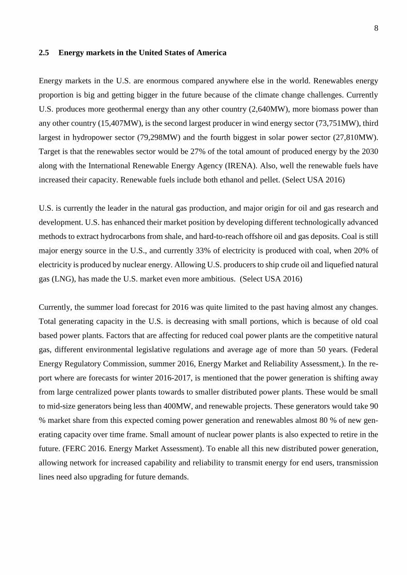
FIGURE 2. Overview of U.S. Electric Power Markets, national view (FERC. National overview.)
In the Figure 2 is presented the overview of the U.S. electric power markets. There can be seen that the
wholesale electricity markets are regionally divided and these transmission systems are operated by spe-
cific ISOs. (FERC. National Overview.)
FIGURE 3. Example of U.S. Electric Region, the New England (ISO-NE) and the California Independ-
ent System Operator (CAISO)

11
In the Figure 3 is presented couple of examples from electric regions, New England on the right side and
California Independent System Operator (CAISO) on the left side. (Federal Energy Regulatory Com-
mission, Electric Power Markets – California and Federal Energy Regulatory Commission, Electric
Power Markets: New England (ISO-NE))
2.5.1 Wärtsilä market position in the United States of America
Wärtsilä is the global leader of reciprocating engine manufacturers in power plant segment. Power plant
business in Wärtsilä is within the Energy Solution business line. Biggest competitors in the power plant
markets having gas turbine technology are the General Electric (GE) and Siemens, which have big mar-
ket share of the large size power plants. Third one is Mitsubishi, and Wärtsilä comes then with rest of
the manufacturers as described in Figure 4. Figure 5 represents market positions of the reciprocating
engine manufacturers where Wärtsilä has the leading position.
One of the advantages in the reciprocating engine markets is the capability to respond quickly to the load
variation caused by renewables. Renewables in that sense increased demand for grid stability which was
also one of the criteria beside the emissions in STEC red gate. It is mentioned in the report that larger
baseload units (e.g. gas turbines, coal power plants and so on) are unable to respond quickly enough and
with certain reliability to the large swings in generation caused by connection of large quantities of
renewables to the grid. Related to the operation of the plant, estimate has been that there would be 730
start ups and shutdowns while the frequency of the operation is unknown. (US EPA. 2014, 5-6, 9-10.)
12
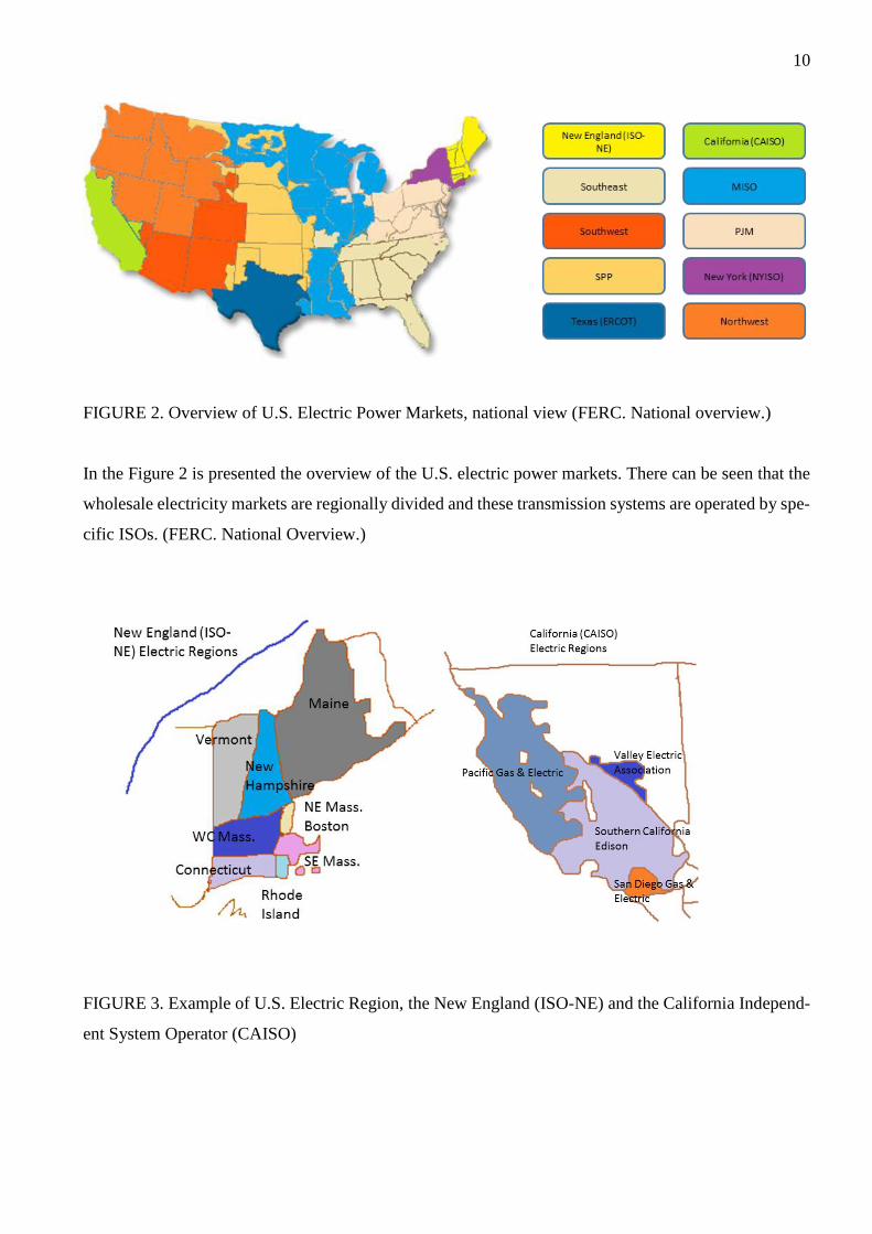
FIGURE 4. Market share, Total market (Wärtsilä 2016. Annual report. 30-31)
Market data presented in Figure 4 includes all Wärtsilä power plants and other manufacturers’ gas and
liquid fueled gas turbine based power plants with prime movers above 5 MW, as well as estimated output
of steam turbines for combined cycles. Other combustion engine manufacturers are not included for this
graph since Wärtsilä has leading position in the engine technology. (Wärtsilä 2016. Annual report, 30-
31)

13
FIGURE 5. Market share, <500MW market. (Wärtsilä 2016. Annual report, 30-31)
Other Wärtsilä business lines within Wärtsilä Corporate are Marine Solutions and Service, which are
as well in strong position globally. Although these are not discussed more within this research.
2.5.2 Products in liability law in the United States of America
Laws in the United States bases on the Constitution of United States which acts as foundation of the
federal government. In Figure 6, this is described as a simplified process.

14
FIGURE 6. Law structuring of the U.S (Burnham W. 2016. Introduction to the Law and Legal Systems
of the United States. 4)
Constitution law of United States defines the top level of law and it is the base for all of the rest. Federal
law defines the boundaries for states laws which simultaneously prevents the different states to collide
with each other laws. (Burnham W. 2016 Introduction to the Law and Legal Systems of the United
States, 4). Product liability law is defined basically in two different forces by Courts and federal and
State legislature and governmental agencies. Court defines the common law and the other one the legis-
lative law. (King L, Prince J.D., Ross K. 2009. Product liability in Asia Pacific, 1)
Standardisation organisations such as American National Standardisation Institution (ANSI), are over-
viewing the development work and adoption of international standards in the U.S. These organisations
have their own process, commonly open for willing participants to participate for development work, to
maintain openness, balance and consensus with variety of bodies using standards. ANSI is an organisa-
tion which closely follows the development work of International Electrotechnical Committee (IEC) and
International Standardisation Organisation (ISO). This works also in opposite way, meaning that the
proposed standards of U.S are taken forward to IEC and ISO and adopted either as whole or partly to
the international standard. Driving force in the standard development is the participants from contrib-
uting industry individuals. (ANSI 2017). This has been opened in Figure 7.

15
Product liability is the area of law, which concerns all parties in the product lifecycle who put products
available to market and are in responsible for the possible injuries the products can cause. The parties
are such like manufacturers, distributors, suppliers, retailers and similar. In the United States, product
liability is claimed concerning commonly negligence, strict liability, breach of warranty and different
user protection claims. Main questions in the product liability law in case of person get injured are
whether the product was too dangerous according to some standard of product safety and has the product
provider complied with duty to warn requirements. (American Law Institute 1998, 7.)
Different categories which are listed as product defect according to the § 2 of American law institute are
referred below. Special attention should be put on the warning defects where the risk level determines
how it should be informed to the user. For example, is it best to inform in the instructions, or next to the
occurring hazard. There are two major principles of products liability law in America, which are manu-
facturer’s responsibility to guard against foreseeable risks and guard against those risks only with pre-
cautions which are reasonable. (American Law Institute 1998, 37, 39.)
“A product is defective when, at the time of sale or distribution, it contains a manufacturing
defect, is defective in design, or is defective because of inadequate instructions or warn-
ings. A product:
(a) Contains a manufacturing defect when the product departs from its intended design
even though all possible care was exercised in the preparation and marketing of the prod-
uct;
(b) is defective in design when the foreseeable risks of harm posed by the product could
have been reduced or avoided by the adoption of a reasonable alternative design by the
seller or other distributor, or a predecessor in the commercial chain of distribution, and the
omission of the alternative design renders the product not reasonably safe;
(c) is defective because of inadequate instructions or warnings when the foreseeable risks
of harm posed by the product could have been reduced or avoided by the provision of
reasonable instructions or warnings by the seller or other distributor, or a predecessor in
the commercial chain of distribution, and the omission of the instructions or warnings ren-
ders the product not reasonably safe.”
Related to product defect, liability and adequate risk reduction in terms of product safety and design
work, it is also important to notice following section in the American law institute;
Ҥ 4 Noncompliance and Compliance with Product Safety Statutes or Regulations In con-
nection with liability for defective design or inadequate instructions or warnings: (a) a
product's noncompliance with an applicable product safety statute or administrative regu-
lation renders the product defective with respect to the risks sought to be reduced by the

16
statute or regulation; and (b) a product's compliance with an applicable product safety stat-
ute or administrative regulation is properly considered in determining whether the product
is defective with respect to the risks sought to be reduced by the statute or regulation, but
such compliance does not preclude as a matter of law a finding of product defect.”
There are couple of examples which are straight related to the design and risk management itself, and
are important from overall safety point of view. It is not worth to list all the sections from the referred
law, but there are numerous similar different sections related also to seller and distributor. Great attention
should be put in the importance to warn user (duty to warn). It is mentioned in most of the points, that
most important thing is to inform user of any possible harm and hidden dangers that can be caused by
the product. It has even higher importance if the warning could have been the adequate risk mitigation
measure for the danger. Negligence in different matters can happen in variety of points of product lifecy-
cle, for example in design, manufacturing, installation and, commission, and it is the most common
claim in the U.S. Processes and responsibilities should be clearly defined to avoid possible situations
where the person could neglect something. (American Law Institute 1998, 30, 59-62)
It shall be noted that the product liability law in the U.S. is state and city specific. A lot effort for this
specific part of law is that the injuries caused from the products are causing enormous costs for the nation
each year. Major part of the injuries are occurred because of improper use of product by user or third
party that would be otherwise safe to use. These are normally out of product liability law but there are
large portion of product –related risks that manufacturer should have reasonable mitigated, and this is
the part product liability law is concentrating. (American Law Institute 1998, 24-30)

17
FIGURE 7. Standardisation organisations and their communication towards states and international
standardisation organisations.
Figure 7. presents different standardisation organisations within the U.S. and how they are connected to
each other. Not all possible standardisation organisations were collected, but only relevant examples
concerning this research. Inner blue box describes that the states has the right to determine what you
must comply with to fulfil product liability requirement for example. Different standardisation organi-
sations provide the standards for use (ANSI. Resources). Following these required standards specified
in some requirement, acts as justification to meet that part of compliance. ANSI is the standardisation
organisation which is the most common organisation to communicate between the international stand-
ardisation organisation ISO and IEC to take standard suggestions for international use and vice versa.
2.5.3 Market argumentation and lobbying
Companies which were included for the market review were Wärtsilä, GE, Rolls-Royce, MAN Diesel
& Turbo, Ahlstrom, Caterpillar and Siemens. Review concentrates on the way how these different com-
panies show the capabilities of way of working in different areas of safety.
Gas turbine manufacturers are presenting different kind of product safety related matters through design
and applications. One of these is the safety integrity level (SIL) of the protective functions and involved

18
equipment such as control system, which is common marketing argument from both technology provid-
ers. There exists also wide range of design handbooks and investigations of hazardous scenarios for
public, which have also been used in this research.
There is not much of organisational information available from the companies if is not taking into ac-
count the general words presented from the importance of safety. Most of the information is available
from the companies who are involved to the nuclear, aviation or similar industries. In some extent, the
safety culture can be seen in the LinkedIn of how large quantity of safety personnel is available in the
company and how they are spread in the organisation. Also in Linkedin, the aviation industry in turbine
manufacturers has the largest product safety and reliability professional network. Some companies do
not allow to log in to see further details or project experiences without intention to buy products. From
MAN, there was example presenting the simplified gate model with project activities including risk
assessments in different lifecycle phases to ensure safe final product. (Laursen R. 2015)
These give impression that the product safety is one of the core values in companies, and can be seen
that the company is at least in some level complying with the requirements where separate safety organ-
isation is needed. Personnel who could be found from LinkedIn are concentrated in various tasks in
different areas of product safety. Usually, if the company has high commitment for safety culture, safety
is in every person’s backbone and part of their daily basis. Safety comes along the processes automati-
cally and separate organisational safety control is not essential.
Since there is not much of marketing of reciprocating engine power plants from safety perspective, it
could be used as marketing value to lob safe and environmental friendly solutions which are considering
the surrounding environment and inhabitants by different safety analysis. For example, MAN power
plants is not promoting safety at all, except for LNG and marine solutions, but even in these only HAZID
and general risk assessment are mentioned, but not very extensive level when considering the industry
practise. (Rolls-Royce, Nuclear Instrumentation & Control brochure; Rolls-Royce, Reactor protection
system brochure; Rolls-Royce, Spinline - modular I&C digital platform for nuclear industry brochure;
Rolls-Royce, Product safety; VDMA 4315-6 2014.)
Some U.S. based engineering companies are representing reciprocating engine technology in their ma-
terial, where also Wärtsilä is mentioned in many of the references with the plant technology information.
There are also benchmarking of the technology listing benefits that can be achieved with the reciprocat-
ing engines. (Burns & McDonnel, Sargent & Lundy.)

19
3 SAFETY IN POWER PLANTS
In this chapter is described in general level what all is included for safety of power plants. First is told
about the health, safety, security and environment (HSSE), and further on concentrating on actual prod-
uct safety. Cyber security is briefly mentioned as one area related, which assess and evaluates power
plant communication and other data transfer, but this research will not concentrate on that particular area
of safety.
The relevant risks for the solution are evaluated during the risk assessments. Most important thing is to
calibrate the risk matrix according (Figure 7) to the application and by using end-users risk acceptance
criteria. This approach is chosen to verify end-users’ capability to fulfil their own as well as legislative
requirements. The additional adjustments needed are done during calibration of risk matrix, and there
the best industry area wise practices for estimating risks and likelihoods shall be taken into account.
Depending on the plant configuration and customer, parameters such as safety, environment and asset
are used to determine risk. Additionally, reputation and asset where the latter one can include plant
performance, equipment damage and other similar matters.
Product safety is wide concept that is mutual with between project stakeholders and surrounding envi-
ronment. Importance of product safety grows even more when the surrounding area has industry or hab-
itants close to the possible new power plant project. The most important phase, when planning the suc-
cessful project is already in the sales phase where the contractual matters are discussed and decided, and
the costs are determined. Layout and nearby industries can have crucial impact to the overall cost and
time schedule when product safety matters are discussed in project execution phase and risk assessments
are done in detail.

20
FIGURE 8. Example of risk matrix
Depending on the customers / end-users’ risk appetite, the risk matrix categories can vary. Safety ori-
ented customers can have higher limit for acceptable risk level than a one who is not safety oriented or
the financing is arranged some other way than through insurance companies.
3.1 Health, Safety, Security and Environment
Health, safety, security and environment (HSSE) is the part which is mainly related to construction,
operation, maintenance and decommissioning phase. HSSE supports all these plant lifecycle phases by
providing instructions and methods how to do different tasks safely and not compromising himself or
others during the task.
There are different legislative guidances’ for HSSE depending on the country where the power plant is
to be build and what is agreed with the end customer. Normally, these are ISO 14001 for environment,
and OHSAS 18001 for occupational health and safety management. In addition, there can be customer
specific requirements or local legislation requirements.
Similarly to product safety, HSSE has their own risk assessments with risk matrixes, which are done for
tasks people are carrying out in any lifecycle phases concentrating to working procedures.
In the U.S., the OSHA law & regulations are giving the frame for health and safety
(OSHA Construction.)

21
3.2 Product safety
Purpose of product safety is to ensure that the end product is safe to use and does not cause harm for
user or to the environment. Different risk assessments are one part of the product safety lifecycle man-
agement and they are done to ensure safety in design. Designer should use his evaluation as daily basis
as a part of his design work and be critical towards own design. Many of the risks can be mitigated
already in design phase. Directives in European Union (EU) lay a foundation to safety requirements for
products, and their requirements are supplemented by applying their harmonised standards.
Risk assessments are needed to be done during design on iterative basis to mitigate risks. It is not possible
to do this by executing one study for some design concept. It is often required to use more than one risk
assessment method and in separate design phases to cover as much of hazards as possible. It is not either
possible to fully remove probability of risk.
There are many different risk assessments for specific purposes and phases of the design. Some of them
are meant for early design phase to screen possible hazards on layout. Some of them are to identify risks
from plant processes that could cause process upsets. Purpose of these is anyhow the same, identify and
set corrective measures based on the evaluation towards end-users acceptable risk level.
Some common methods which can be used in gas power plant applications and are common industry
wide;
- Hazard identification (HAZID)
- Hazard and operability study (HAZOP)
- Fire (and explosion) Risk Assessment (F(E)RA)
- Layer of Protection Analysis (LOPA one method for safety integrity level (SIL) allocation)
- Quantitative Risk Assessment (QRA)
It is possible to analyse risks of the power plant or nearby industry towards the power plant by using
different risk assessment. Some of these are concentrating for the layout to evaluate impact of different
equipment location, and locating them in to right places based on their type of risk. Then, with the actual
process risk assessments can be evaluated the process risks, e.g. is there enough safety shutoff valves,
and with what partitioning or adequate level control with certain alarms and actions. Beside these there
are also risk assessments to evaluate operability, machine-human interface, maintainability and much
more.

22
Going further to more analytical methods, quantitative methods like fault tree analysis (FTA) can be
used for investigating reliability and availability of a larger and more complex system. Similar qualita-
tive tool is event tree analysis that can be used for root cause analysis (RCA) tool for hazardous event
investigation, such as what all failures and tasks have been part of some hazardous event. With these
sort of methods, overall plant configuration can be evaluated to reach certain reliability and availability
for some estimated time period. Of course, in these the source for component failure rates and simulation
tools have great impact for the calculation reliability.
Knowhow of different consultants are often from the Oil & Gas segments or in general from the process
industry, and then they are comparing the requirements from there to power plant installations. This is
not very reasonable since the risks are very different and more related to the reliability of power produc-
tion to the network. Amount of fuel, which can be typically either liquid fuel oil or natural gas is con-
siderable lower than in a process plant, refinery or oil rig where the typical guidelines have been devel-
oped.
Cyber security is one part of the overall safety of any plant communications. Figure 8 describes the
principle that each network segment is secured from each other to prevent unauthorised access and mod-
ifications to communication. From safety point of view, especially the safety instrumented system (SIS)
is critical in terms of controlling all safety critical functions in a plant. Cyber security is one part of the
risk assessment that is assessed, where all the possible security threats should be identified and mitigated.

23
FIGURE 9. Example of cyber security topology segmentation for network security (Gilsin J. 2013.)
Cyber security has important part especially in critical plants that are either hazardous in case of accident,
or critical part of operation of some bigger system. Such can be for example power plants for data centres
and process industries.
Generally, it is important to do assessment on the layout and location for power plant installation. This
is extremely important in the environments where exists nearby industries, inhabitants or environmen-
tally important matters that can be harmed. If the plant is located next to process plant or similar that
may have an effect to the power plant, it should be always included to the analysis so that the interfaces
and hazardous impacts are investigated. HAZID can be done in very early phase to have screening of
hazards that exist at the site and updated in later phase after design changes. In a later phase, these
findings can be transferred for the QRA to do more detailed evaluation to have impact assessment of
those hazardous events. HAZOP is done at least for the process system in basic and detailed design phase
to identify risks during the design phase and after the design implications. Depending on the acceptable
risk levels, which are end user’s responsibility to provide as an input to the risk assessment, LOPA can
be carried out to set additional risk reduction measures with safety instrumented systems with specific
safety integrity level (SIL).

24
In relation to the interfaces, one essential part of complete electricity production is the transmission and
distribution part which is one major interface in respect of safety, reliability and availability, and con-
cerning all technologies of electricity production. Many of the risks related to this are downed power
lines resulting from some external causes like storm, falling trees or vehicle crash. Similar to all risk
assessments, the boundaries and interfaces for evaluation shall be determined and justified as reasonable,
and for correct responsible parties. (EPA-600/7-77-016 1997, 33-35.)
SIL for specified function is always depending on the risk reduction needed when comparing the gap
between identified risk and acceptable risk level. A specific SIL should not be determined as starting
point of risk assessment, as it is the outcome of the risk assessment. In order to determine SIL level, at
first it is needed to know the actual risk, how often hazardous scenario may happen, possible occupation
near the risk, and is there some conditional modifier that can make identified risk even worse. After
these can be determined what is the safety function subject to SIL, and what can be used to reduce the
risk either as preventing or mitigating function.
3.3 Accidents in history of energy industry
One major accident cause in the gas turbine plants has been gas pipe cleaning in the commissioning
phase. As part of the installation, gas pipeline to the turbine is installed as part of construction phase.
Due commission and other reasons, debris can remain in the pipeline which requires cleaning of the
pipeline to avoid causing gas turbine damage. Based on the history and accidents described in the fol-
lowing chapters, procedures are developed and now the appropriate ways are used to clean piping. The
cleaning techniques are such as using pigging with air or nitrogen, air blows, nitrogen blows, steam
blows, water and chemical cleaning. Common to these all was that it is not certain how much of gas is
adequate to blow debris from the pipeline and this can cause extensive amount of gas accumulation in
worst scenario. For example in the Kleen case, Siemens had provided the recommended Cleaning Force
Ratio (CFR) which is needed to clean the piping but there was no upper limit for this, which resulted
much higher gas release than was needed for the cleaning purpose.
One of the biggest gas turbine accidents happened 2010 at Connecticut, Kleen Energy Systems power
station in U.S. The power plant construction was started in 2007 and it was scheduled to start supplying
energy in June 2010.

25
“The blast at the 620MW, Siemens combined cycle gas and oil-fired power plant occurred
at 11:17 am, and was reported at 11:25 am EST. The plant's manager, Gordon Holk, said
that contractors and other workers from O & G Industries, Ducci Electric, and Keystone
Construction and Maintenance Services were at the site when the blast occurred. The ex-
plosion occurred at the rear of the largest building, the turbine hall, which was destroyed.
Six workers were fatally injured during a planned work activity to clean debris from natural
gas pipes at Kleen Energy in Middletown, CT. To remove the debris, workers used natural
gas at a high pressure of approximately 650 pounds per square inch. The high velocity of
the natural gas flow was intended to remove any debris in the new piping. During this
process, the natural gas found an ignition source and exploded.” (CSB. Kleen Energy Nat-
ural Gas Explosion.)
Safe handling of natural gas is important factor in U.S. markets to be presented both in design and op-
eration, as well as the complete lifecycle of the power plants. OHSAS did not have a clear safe handling
procedures for natural gas at the time of Kleen accident. On the day of the incident, the plant personnel
cleaning the pipe did not have a safety meeting to discuss about the risks of gas blows nor reviewed the
blow procedures. Design and the gas blow pipe orientation caused the gas accumulation between the
heat recovery steam generator buildings, which were all affecting for the gas dispersion. Kleen accident
caused urgent actions from chemical safety board to develop procedures for safe handling of natural gas
in OHSAS, and additions for NFPA and American Society of Mechanical Engineers (ASME). One of
the developed standards related to this accident is NFPA 56 which is prohibiting the use of flammable
gas to cleaning purposes. (CSB. Kleen Energy Natural Gas Explosion)
Comparable accident happened also in 2003 at Calpine’s Wolfskill Energy Center gas plant in Fairfield
California, where was also performed a gas blow during the pre-commission phase. Similarly, there was
a large confined space where the gas accumulated and ignited. Probable reasons considered in the inves-
tigation were the static electricity from the high velocity gas flow or from debris causing spark due
collision to metal structure. Also in this accident, there was identified that safer methods for cleaning
the pipe could have been used since natural gas is not the only way to clean the pipes. ((CSB Urgent
Recommendations; Calpine.)
In 2001, there was also a gas blow accident in the commissioning at FirstEnergy power generation station
in Lorraine, Ohio. Temporary short pipe was installed and for some reason the natural gas ignited due
unknown metal spark causing high flames from the stack. Personnel damage was avoided but property
damage was caused. (CSB Urgent Recommendations.)

26
List of actions were presented for all gas turbine manufacturers to address for customers for safe opera-
tion and maintenance of gas turbine plants. Later, there has been development in the NFPA committee
to make more stringent requirements for the large gas piping purging to avoid similar hazardous scenar-
ios. Also, alternative inherently safe ways to clean gas piping have been presented and required to be
followed. (CSB Urgent Recommendations.)
There are numerous hazardous scenarios reported and collected for the database, which increases the
reliability of investigation and development work. Collected incidents include both gas leakages which
have created an explosion as a result of ignition, and other scenarios have been blade failures resulting
as casing rupture and small fire. Fuel releases have occurred during the start-up from the loose flange
and fuel changeover. One major matter to be noted for the explosion scenarios in this is that it has sig-
nificance if the turbine is located onshore or offshore. Also there is always companies whom are not
reporting the dangerous failure scenarios. (Santon R.C. 1997, 53-54.)
These examples show also the importance of the risk assessments; when design follows only the require-
ments for gas pipe cleaning process by using natural gas presented in the NFPA standard, it does not
take into account all possibilities of hazardous scenario that might come up because of e.g. unexpected
ignition sources. If there would have been a risk assessment covering also these hazards, this scenario
might have been noticed, and blowout would have been done up to atmosphere and not towards the plant
buildings.
There is possibility that all the accidents which have happened in the power plants are not reported
publicly, which is normal silently accepted procedure amongst the industry. Process safety incidents are
reported only if the occurred incident is process related. Break of coupling in turbocharger at a power
plant without the appropriate usage of overspeed protections would not been reported as process safety
incident, since it has no chemical product associated. All in all, it can be summarized that risk reporting
is not aligned between industry areas. (AIChE, Process safety in power plants.)
Investigation and reporting of accidents, and related equipment failure is essential also for the develop-
ment of data bases used for reliability calculation. Many industries are using the generic data bases most
often collected from process industry to do quantitative risk analysis. For the company itself whom is
delivering the product, the collected and correct data of the products from the field is more important.
With the information, different scenarios can be justified and can be used to estimate the test and mainte-
nance intervals to prevent hazardous scenarios as well improving the overall reliability of the product.

27
3.4 Legislation and codes
There exist a lot of standards, legislative norms and guidelines for gas turbines, which are used for the
safe design of gas turbine applications and power plants. Some identified similar standards guiding gas
turbine and reciprocating engine power plant design safety is listed in Table 1 for comparison. In both
technologies, there are some standard state-of-the-art level of design which applies to legislative require-
ments, and if there are some local requirements which are more demanding and better, these are pre-
sented by the end-user. More comprehensive list is presented in Appendix C, though both of the tables
are not complete so these should not be taken as reference without a further investigation.
TABLE 1. List of some product safety standards used in the gas turbine and reciprocating engine power
plants
Standard Code Standard Name Gas turbine
power plant
Reciprocating
engine power
plant
IEEE The Institute of Electrical and Electronics Engineers
(Multiple standards) X X
NEC National Electrical Code (Multiple standards) X X
ASME American Society of Mechanical Engineering (Mul-
tiple standards) X X
Machinery di-
rective
The Directive 2006/42/EC of the European Parlia-
ment X X
ANSI EN ISO
12100 / ANSI
B11.0
Safety of machinery - General principles for design -
- Risk assessment and risk reduction X X
IEC
61508/61511
Functional safety of electrical/electronic/programma-
ble electronic safety-related systems X X
ISO 7919 Mechanical vibration of non-reciprocating machines
– Measurements on rotating shafts and evaluation cri-
teria
X N/A

28
TABLE 1. List of some product safety standards used in the gas turbine and reciprocating engine power
plants. (Continued)
ISO 21789 Gas turbine applications - Safety X N/A
IEC 60079 Electrical apparatus for explosive gas atmospheres,
Part 10: Classification of hazardous areas, X X
IEC 60204-1 Safety of machinery – Electrical equipment of ma-
chines – Part 1: General X X
IEC 61140 Protection against electric shock - Common aspects
for installation and equipment X X
NFPA 37 Standard for the Installation and Use of Stationary
Combustion Engines and Gas Turbines X X
ASME GT-90-
GT-375
Experiences with external fires in gas turbine instal-
lations and implications for fire protection X -
National Fire Protection Association (NFPA) is a trade association of the U.S which develops and pub-
lishes consensus codes and standards for the purpose to eliminate death, injury, property, and economic
loss due to fire, electrical and related hazards. These standards are adopted and used widely around the
world. There are number of standards related to the fire protection, gas and explosion, which are used
industry wide, but this research does not examine those in detail. (NFPA, Codes and standards.)
ASME is the leading international standards and codes developer for art, science and mechanical engi-
neering. These standards and codes are developed to guide and improve public safety, health and quality.
Market needs drive the standard development work, and there are more than 100 nations which are using
the codes. (ASME, Standards and certification)
NEC is the national code for electrical installations, and it is adopted by the state law and local jurisdic-
tions, which makes it more U.S specific compared to other codes and standards. NEC is also known as
NFPA 70 and it is concentrating on the electrical installations and wirings. (NFPA, Codes and standards)

29
Based on accident reviews referring to earlier chapters, U.S. parties who make the guidance for safety
in order to develop requirements further based on the accidents happened in the industry. The similar
approach is also used in the European Union where major scale accidents have happened.
There are referring standards developed specifically for gas turbines based on hazardous scenarios which
are dealing with hazards, such as the acoustic chamber and fuel supply explosion hazards. These are
been presented below.
“Standard for the Installation and Use of Stationary Combustion Engines and Gas Tur-
bines, National Fire Protection Association (USA), 1994 (NFPA 37) is a fire protection
standard but recognises the explosion hazard and recommends the provision of explosion
relief for turbine enclosures, or the provision of "ventilation adequate to prevent a hazard-
ous accumulation of flammable vapours or gases..." Adequate ventilation is not defined
further. In the case of an engine handling hazardous material other than its own fuel supply,
i.e. a gas turbine driven gas compressor, there is no alternative to the recommendation of
explosion relief. The scope of this code is limited to engines and turbines not exceeding
7500HP, i.e. 5.6MW.
Gas Turbines for Refinery Services, API Standard 616, Third Edition, American Petroleum
Institute, 1992 (API 616) is essentially a purchasing specification but includes some rele-
vant recommendations. It requires exhaust system purging, an automatic vent on any gas
fuel supply, the minimum of flanges and flexible pipework, and insulation, or guarding, so
that no exposed surface exceeds 74°C. (Since guards are permitted, this requirement is
probably directed towards protection for operators rather than ignition risks.) It makes no
specific reference to ventilation or other explosion mitigation means. A later similar code
Recommended Practice for Packaged Combustion Gas Turbines, API Recommended Prac-
tice 1 IPGT, First Edition, American Petroleum Institute, 1992. (American National Stand-
ard ANSI/API RP 11PGT-92, Approved July 1993) is directed specifically at packaged
plant. It refers to acoustic enclosure ventilation as having a purging duty but gives no safety
specific guidance on it, and it extends the fuel gas supply shutoff requirement to two valves
and an automatic vent.
Publication IM/24, Guidance Notes on the Installation of Industrial Gas Turbines, Associ-
ated Gas Compressors and Supplementary Firing Burners, British Gas, June 1989. (IM24)
is a broad code covering the whole installation from fuel supply to instrumentation. It refers
to the need to provide adequate ventilation, and quotes 1m3/Vsec as the minimum for gas
leakage ventilation. It refers to gas detection for some circumstances, but stresses that it
should not be regarded as a substitute for good ventilation.
Area Classification Code for Petroleum Installations, Model Code of Safe Practice Part 15,
Institute of Petroleum, 1990. (IP 15) is a general area classification code for Petroleum
Installations. It contains extensive discussion on the adequacy of ventilation, and a specific
section on the ventilation and classification of turbine enclosures, or hoods, and the rele-
vance of this ventilation to the prevention of the accumulation of flammable mixtures.
Significantly it permits the enclosure to be classified as safe (unclassified) during normal

30
operation if dilution ventilation is present, recognising the effectiveness of properly de-
signed ventilation in preventing accumulation.
The concepts of Adequate Ventilation and Dilution Ventilation are well recognised in area
classification. Adequate ventilation is intended for applications where the probability of
release is limited and unlikely to be sustained for a prolonged period, whilst dilution ven-
tilation is intended to be high enough to dilute below the Lower Explosive Limit (LEL)
any reasonably foreseeable leak. The concepts are discussed further in IP 15 and Cox, A.
W., Lees, F. P., and Ang, M. L., 1990, Classification of Hazardous Locations, Institution
of Chemical Engineers.. In both cases it is essential that there are no stagnant regions.
Adequate ventilation, as defined, is not appropriate for releases that may be prolonged or
where the probability of ignition is high, as is the case in both respects in an acoustic en-
closure. IP 15 notes, in respect of dilution ventilation that "The design of the ventilation
system must ensure that there are no stagnant regions and that the immediate mixing and
dilution are as required." “(Santon R.C. 1997, 54-55.)

31
4 DIFFERENCES BETWEEN POWER PLANT TYPES
There are differences between the turbine and reciprocating engine power plants, but in some extent,
they are similar with each other. Main differences are the power production equipment with supporting
auxiliaries and amount of those in the plant. In turbine power plant, there are commonly from one to five
turbine units depending about the operation mode and supplied production capacity. In reciprocating
engine power plant there, can be engine-generator sets from 1 to 40 or even more depending on the
operation mode and capacity that will be supplied. Because of this, the maintenance, maintenance sched-
uling and risk management is important in gas turbine plants since loss of one unit has significant effect
for the plant operation and output. This is one of the major technology risk related matters that customers
consider between the gas turbines and reciprocating engines. Reasons for the increased risk is the cost
impact raised from number of equipment which require maintenance during the plant lifetime.
Another difference between these power production types is the control system, and that the operation
mode of the plant is controlled. Turbine plants are at their best when operated as baseload power plants
with the full capacity. Then the operation is continuous with less starts and stops including continuous
power production. Process risk assessment, by identifying the critical deviations in the system, gives
input to the reliability/availability analysis when unintended shutdowns and trips can be avoided. Re-
ciprocating engine power plants are at their best in all different operation modes including baseload,
peak load and emergency response. Reciprocating engine power plant can be started and stopped within
short period of time (minutes). Different operation profiles can be developed for operation modes, e.g.
some engines are running more than others as “forerunners”. Plant configuration can also be divided to
partly run with baseload, and partly with peak load. These were also raised as technology risks from
customer point of view. Operation of different modes and configuration of engines is unfamiliar for
turbine operators.
In flexi-cycle plants, including steam turbine and condenser the plant configuration and its auxiliaries
hardly differ, regardless of the configuration of the power production. Especially in the steam turbine
plants, the cooling system has an important role in overall system operation. Cooling system is control-
ling the steam temperature which has impact on the steam pressure, and when variating too much may
cause damage to the system. Also, breakage of cooling water system may lead to cooling water leakage
to steam condenser, which would further cause liquid carryover to turbine and damage the turbine blades.

32
Turbine plant requires more space to be fit in the surrounding environment compared to the reciprocating
engine power plant. This is important factor when evaluating the plant layout and how it can be built,
for example near the industry or community to provide safe and environmentally friendly solution to
mitigate possible risks. Size of the turbine or reciprocating engine power plant was not raised as a risk
factor, but other environmental matters like noise and emissions are normally discussed in the sales
phase.
4.1 Common risks in both power plant types
Common risk in both power plant types is variation of the fuel supply that is connected to the plant.
Risks related to the layout are similar in both power plant types, as both gas and fire can cause escalating
major hazards. Due higher volumes of fuel in turbine power plant, the consequence is more severe. In
relation to this, the power plant interfaces are equally important in both power plant types.
From technology point of view, the risk causes are similar, e.g. overspeed, high gas pressure, and loss
of power. In the both technologies, the electrical and compressed air systems are crucial due the plant
control. Both have impact on availability and reliability of the power plant, if there is failure that can
cause unintended shutdown.
The previous two paragraphs were about actual product safety related risks which were araised in liter-
ature review. Risks and safety function requirements for turbines were presented both in standards and
accident investigations. In the interviews, typical risks presented by customers focus more on the Ex-
layouts and how these are considered in the plant design.
4.2 Turbine power plants
In this research, the focus is in gas turbine power plants since the reciprocating engine technology also
uses fuel gas technology. Other alternate turbine technologies are briefly described below, and the over-
all content concentrates for safety and differences with the reciprocating engine technology. Figures 9
and 10 present simplified processes of gas turbine and combined cycle gas turbine cycles.

33
FIGURE 10. Simplified picture of gas turbine cycle
FIGURE 11. Simplified picture of combined cycle gas turbine (Kehlhofer 1997, 3)
Reciprocating engines are often used to deal peak loads due to their fast start-up time, low initial cost
and short delivery time. In terms of start-up times for gas turbines, the time frame is around 30 minutes
and design life of approximate 3000 starts depending on the turbine type (Lipiak 2006, 3,5). Annual
start-up amounts are much less than with reciprocating engines and the start-up time is considerable
longer. This is one of the reasons beside efficiency and unit output, why turbine technology is most often

34
used as a baseload. Gaseous or vaporized fuel is injected into a combustion chamber together with com-
pressed incoming air. The resulting high-pressure and high temperature exhaust are used to drive the
turbine which in turn drives both the generator and the compressor (Giampaolo 1997. 71-72, 79-82.)
A combined cycle gas turbine power plant (CCGT) is flexible and more efficient turbine plant. It is
similar to gas turbine plant by its design with the difference that there is waste heat recovery system
collecting the steam from process in to the boiler driving steam turbine that generates electrical power.
Generalised turbine plants consist of main power production units, supporting auxiliaries, electrical
equipment and control system similar to reciprocating engines. The differences are amount of units,
operating modes and process values such as operating speeds, and the fuel supply pressures and capacity.
(Giampaolo 1997. 85-104; Kehlhofer 1997. 171-221.)
Due the size of gas turbine and turbines in general, the required inertia and torque required to start ro-
tating of the turbine shaft requires external power for the start-up. There are different solutions, but
commonly diesel motors are used for this, and with the gearbox and clutch the disconnection is enabled
after turbine start and speed increase. (Giampaolo 1997, 85-89)
4.3 Safety in gas and steam turbine power plants
In this section, the main safety risks are described. In addition, possible and scenarios happen in history
is reviewed. The review is based on the available material by the hazardous accident investigation reports
by safety authorities, available risk assessments and related literature.
Highest risks are related to the turbine itself. The highest single risk considering the damage either in
asset value, safety, reliability or availability is related to the over speed and breakdown of turbine. This
is because of the high speed of turbine (normal operation speed around 3000 rpm) during operation and
the overall rotating mass of it (10 to 20 tons depending on the gas turbine size). Loss of over speed
protection would mean loss of the only safeguard against this scenario, and in case of failure it would
cause damage to the plant, operators and personnel depending on the plant setup. Other significant risks
in different parts of the systems based on the Hazard and Operability study are related to the high pres-
sure that can cause fatality, loss of production or severe damage to the equipment depending on the fluid
e.g. steam or gas. Another high-risk item is related to the start-up of the system. Also most of these risks
35
are related to the high pressure in the system creating a risk for steam explosion or substance carry over
in the system either due to the system operation as automatically or manually by operator.
Generally, the risks are either personnel or asset related risks. Asset related risks are caused mainly by
turbine damage since it is the most expensive and most critical item for the plant operation. Delivery
time for turbine is also long, which will have great impact for the plant availability in case of failure.
The most severe accidents which may occur at a gas turbine plant are explosion, asphyxiation and rup-
tured lines. Explosion, with possible sub-sequent fire, can occur in the turbine, compressor combustor
and recuperator. Explosion and fire typically occur because of fuel mishandling or component failure.
Probable scenario related to gas is the accumulation of flammable gas within the turbine and associated
exhaust system, which is ignited by the combustion process itself example in star-up phase. This is
common hazard in any gas related application and can be mitigated if identified in the design and cor-
rective measures are allocated. (Santon R.C. 1997, 53.)
Power failure may result from explosions from electrical malfunctions, breakdowns, circuit overloads
or human error, and from accidents involving transmission and distribution of electricity. (EPA-600/7-
77-016 1997, 33, 229.)
In gas turbine and steam plants, explosions may occur in the fluidized bed-combustor system with ejec-
tion and dispersion of the bed contents. The containment vessel in an atmospheric fluidized bed system
could rupture as a result of accidental pressurization, whereas pressurized vessels can suffer burn-
through and explode. Both atmospheric and pressurized fluidized bed systems, fired with coal, also run
the risk of fire from spontaneous combustion. An additional accident which may occur in gas turbine
plants is asphyxiation from toxic working fluids. Two developmental gas turbine systems, integrated
low-BTU gasification and refined coal, could release toxic substances such as hydrogen sulphide, carbon
monoxide, and coal tar volatiles from leaks, pressure ruptures, process failures, or by human error. The
fluidized-bed coal combustor could release alkali metal hydroxides through leaks, pressure ruptures er-
ror or spilling. In the condenser or boiler, an accident could occur, which would result in an alkali metal
water reaction causing fire and explosion. (EPA-600/7-77-016 1997. 229; Santon R.C. 1997, 51.)
Gas fuel supply for a gas turbine requires a high pressure which can be example for 6MW unit around 8
to 20 barg and a 40 MW unit can take 10 tons in hour up to 30barg. Piping design can be challenging
since the design is dependent about unit size and each chamber might require multiple main fuel supplies,

36
and also alternative fuel supplies. For example, for 250 MW unit the design may include over 200
flanges, 90 flexible hoses, 18 valves and 8 bellows all operating at 20 barg and liquid fuel supplies may
operate around 60 barg. Absence of isolating valves in fuel supply system causes similar problem as in
process industry that in assembly or maintenance phase it is not possible to test final connection of the
piping due difficult access. Probable scenarios (to happen once in a two-year period) related to the fuel
pipelines are the leakages due to maintenance and also from random vibrations. (Santon R.C. 1997, 52.)
Similarly, to reciprocating engine power plants the site, access, ventilation, fuel pipework and explosion
relief design shall be justified with the appropriate risk assessments, and further, implement the needed
design solutions. Site selection is affecting to the plant design through many matters such as natural
ventilation. In addition, the environment having emission and noise limits need to be considered. Gas
accumulation to the plant and engine / turbine hall affect to the ventilation design and to the gas detection
measures. Access to the plant and different areas where operator can be exposed to hazard shall be
always minimised and only permitted according to designed procedures. (Santon R.C. 1997, 57)
Detectors should be located near potential sources so that the leaks are detected. Ventilation and plant
shutdown procedures with possible interlocks shall be designed as safe to minimise further escalation.
Explosion relief valves are recommended as risk reduction measures if the dilution ventilation is not
practicable, as relief valves has been justified as proven reliability. Location of these can be either out-
doors or indoors depending on the site layout. To minimise subsequent damage due the relief valve
opening and fire, emergency shutdown with fuel supply shutoff can be considered during the risk as-
sessment. Important matters on fuel pipework is the amount of connections to minimise all possible
leakages. Double containment and relevant safety shutoff valve design should be considered. (Santon
R.C. 1997, 57-59.)
4.4 Components
In the following chapters, main components of the combined cycle gas & steam turbine power plants are
gone through andsome of the challenges are identified. For example, what limitations those might have
and what are the options in between relevant system for plant to be selected to achieve best and optimal
plant for use.

37
4.4.1 Gas turbine
The most important, expensive and largest single component in the turbine plant is the gas turbine itself.
The both combined cycle and steam turbine technologies use similar type of turbine technology and
from these the combined cycle has become competitive only because of rapid development of the higher
gas turbine inlet temperatures. Also, the compressor unit has been developed during the time and by now
it can take higher mass flows and pressure ratios enabling higher power outputs reducing costs and
improving the overall efficiency. (Kehlhofer 1997, 171.)
Because of fast development of the gas turbines, they have faced some negative impacts in the availa-
bility. Turbines have been primarily developed for use as independent units. Due to fuel cost rise, the
development for improving efficiency has been fast, which has been the cause for high turbine inlet
temperatures that affects availability. Today these issues have been fixed and reliability and availability
has increased enabling in large base-load or medium-load combined cycle plants with the as high avail-
ability as conventional steam turbine power plant. (Kehlhofer 1997, 172.)
Another great impact and concern is the fouling of compressor which operates in an open cycle drawing
air which is always a bit dirty despite the air filtration. Turbine fouling is a problem if dirty fuels are
used. These have become higher concern than the previous inlet temperature problem. Compressor is
impossible to keep completely clean, and this eventually causes losses in output and efficiency, that are
greater in single-cycle than combined-cycle due to the fact that steam turbine can be used for recovery
of losses. Two different methods have been used to recover efficiency losses which are (Kehlhofer 1997,
172-179.)
1. Dry cleaning using nutshells or rice
2. Washing
Washing has been the preferred method since it does less damage to the compressor blades protective
coating. In both cases, it requires shutting down and cooling to have efficient clean-up, which means
approximately 24hrs shutdown. (Kehlhofer 1997, 172-179.)
Turbine fouls mostly because of ash in contaminated fuels. Another important factor is the additives
used for high temperature corrosion prevention. Fouling is a problem especially in base load plants. In

38
medium load and peaking load plants, the self-cleaning affect by the start and shutdowns. Comparable
low speed washing of cooled turbine and compressor enables to recover 50-80% of losses. (Kehlhofer
1997, 179.)
4.4.2 Compressors
Used compressors are either centrifugal design or axial design type. Compression ratios have been sig-
nificantly increased from the past. Compressors provide the high pressure, high volume air / gas flow to
turbine providing the power output for the process. Depending on the size of the unit, compressor type
will vary between axial and centrifugal, where axials are used in bigger applications. (Giampaolo 1997,
52-64.)
4.4.3 Waste heat boiler
Waste-heat boilers connect the gas turbine to gas and the steam processes. There are three main types
which are presented in the following chapters.
Both conventional and fluidized bed boilers are a serious source of hazard because of potential explosion
risk. Boilers are operated with a high pressure which can present an explosion hazard. Explosion prob-
ability will be increased by high temperature and erosions. Beside these, the fire and coal dust explosions
increases the pressure of boiler multiple times. Tube rupture in the boiler may occur causing some equip-
ment damage with shutdown. (EPA-600/7-77-016 1997, 229.)
Waste-heat boiler without supplementary firing
Waste-heat boiler without supplementary firing is basically a heat exchanger. Operational requirements
set difficulties for this system, and one of the major concerns is the short start-up time of the gas turbine.
Waste heat-boilers without supplementary firing can be built based on steam generator with forced cir-
culation or natural circulation. (Kehlhofer 1997, 180.)

39
Combined cycle plant gain advantages from the forced circulation because of its vertical design, fast
start-up, suitability for designs with a low pinch point and smaller sensitivity to steaming
out in the economizer. Major benefit of natural circulation boiler is that no circulation
pumps are needed. (Kehlhofer 1997, 180.)
The optimum waste heat boiler must meet the following conflicting-conditions:
- Ratio of waste heat application must be high (high efficiency)
- Pressure losses on the flue gas side must be low in order to avoid losses in both output and
efficiency of the gas turbine
- Low temperature corrosion must be avoided
- Acceptable pressure gradient during start-up must be wide
These conditions are difficult to achieve simultaneously. Because of the temperature difference there
will be heat transfer (negligible because it happens with radiation). Surfaces required for the heat ex-
change would be large for good rate of waste heat utilization, which means pressure losses. This problem
can be solved with small diameter finned tubes but its thermal capacity will be small and it favours quick
changes in load. (Kehlhofer 1997, 181.)
Problem in the waste heat boiler design is concerning the surface and its area. Operational issue is the
ability to respond fast for start-up of gas turbine. Cost of the waste heat boiler is depending a lot of the
surface installed. Area of the evaporator increases exponentially as function of temperature (differential
decrease), while the increase in steam generation is only linear. Too large heat exchanger surface can
cause pressure losses on the flue gas side reducing a bit of the output. (Kehlhofer 1997, 182.)
Operational issue is that there are large differences in specific volume between water and steam at low
and medium pressures, which cause large amounts of water to be expelled from the evaporator at the
start of the evaporation process. If the drum cannot take this water, there will be great losses of water
through emergency drain on each start-up. The gross volume of the drum should therefore be 1.5-2.5
times as great as the volume of the evaporator steam in normal operation. Volumetric change can be
controlled with employing recirculation so that at least no steaming out occurs in the economizer.
(Kehlhofer 1997, 188.)

40
Waste-heat boiler with limited supplementary firing
Principle of this operation is similar to waste-heat boiler without supplementary firing. Firing itself has
various design options. The principle is mostly used technology when natural gas is used, since it allows
uniform temperature distribution after burners and the radiation to the combustion chamber walls will
be limited. Burners are available for burning oil also, but since it causes more problems than benefits it
is preferable to look other solutions. Evaporator is consisting of natural and forced circulation processes.
Major advantage of boiler with cooled combustion chambers is its operating flexibility. Control of the
supplementary firing enables the maximum temperature to be more than 750C. Benefits comes up in co-
generation applications and such where broad control range is required for the process steam flow at
different gas turbine loads. (Kehlhofer 1997, 189-192.)
Steam generator with maximum supplementary firing
With this type of steam generator it is not correct to speak about a waste heat boiler. This is because the
heat content of the exhausts is small in comparison of the output of the firing in the boiler. Exhaust gases
from the gas turbine are used primarily as oxygen carriers. Design is closer to a conventional boiler with
the exception that there is no regenerative air preheater, because exhaust gas temperature is already high
enough. Economizer is needed to reduce the temperature of exhaust gas after the steam generator to a
normal temperature. The best arrangement divides the feed water between the economizer and the high
pressure feed heaters. When gas is used as fuel, additional low pressure part of flow economizer im-
proves efficiency. The fuel burned in the boiler may be oil, gas or pulverized coal. (Kehlhofer 1997,
192-193.)
4.4.4 Steam turbine
Steam turbine must possess the two main characteristics which are high efficiency and short start-up
times, and these are concerning all installations without supplementary firing. Short start-up times are
important for combined-cycle plants which are often medium-load units as peak plants having daily
start-up and shut-downs. (Kehlhofer 1997, 193-197.)

41
4.4.5 Generators
Most of the gas or steam turbines used in combined-cycle plants are connected directly to the turbo
generators. The typical turbo generator types used in combined-cycle plants as presented by Kehlhofer
(1997) are listed below;
- Air-cooled generators with an open-circuit cooling system
- Air-cooled generators with an closed-circuit cooling system
- Hydrogen-cooled generators
Preferred option has been the open-circuit air cooling because of costs and cooling requirements, but it
is vulnerable to fouling and noise. Closed-circuit systems have been built for capacities up to approxi-
mately 200MV A. They are reasonable in cost and also problem free in operation efficiency being high.
Hydrogen cooled generators have possibility to achieve even higher efficiencies but they need additional
design, auxiliaries and monitoring equipment, which are increasing the overall cost. (Kehlhofer 1997,
197-198.)
4.4.6 Electrical equipment
Combined-cycle gas turbine plant is similar with conventional power station containing some turbines
what comes to the typical single-line diagram. Power for the station operation can be supplied either
from each gas turbine or from the steam turbine separately, but the gas turbines can provide needed
power for the steam portion auxiliaries also. It is common in smaller combined-cycle plants (less than
100 MW), that there is no medium voltage (MV). Related auxiliaries are though equipped with low
voltage (LV) motors. (Kehlhofer 1997, 198.)
4.4.7 Control and control equipment
The control system is the most important part of the power plant also in turbine plants as it is in all
industrial applications. Its purpose is to control and protect enabling safe operation as well gather the
data. Standard gas turbine is supplied as fully automated machine. The steam process requires to take
interfaces and calibration of process in to account so that these are all corresponding each other. The

42
plant mechanical part and processes are simple compared to control system since these are making the
plant complex as whole. (Kehlhofer 1997, 198-201.)
Hierarchic and distributed structure for open and closed loop control systems is best ratified for the
complete process. This will make it possible for simple planning, commission the plant in stages and
raise the availability of the power plant. (Kehlhofer 1997, 201.)
Kehlhofer (1997) introduces drive level and the functional group level, which both have specific func-
tions. In the former, all individual drives are controlled and monitored, and safety devices in the switch-
gear act directly on the switches and the relays. All these signals are sent both to the logical control
circuits of the drive level and to the higher hierarchic levels. On the latter, the individual drives for one
complete fraction of the process are gathered together into functional groups. The logical control circuit
on this level comprises interlocks, automatic throw switches and preselection of drives. (Kehlhofer 1997,
198-201.)
The turbine protection control is used to monitor speed, temperature and vibration, which are such crit-
ical process parameters that can cause hazard with severe consequence to the operation, asset or / and
for personnel. Similar to all industries, different levels for alarm and shutdowns are used to allow oper-
ator action if there is time to perform needed action or the plant operation is more critical than automatic
shutdown. Overspeed protection is one example function that is automatic due to its extremely fast oc-
currence and severity. Its typical causes are excessive fuel flow or loss of load (as a result of coupling
failure). (Giampalo 1997, 81.)
Temperature protection is used to protect against excessive high temperature but also to protect exces-
sive temperature spread. Use of multiple temperature sensors is based on the protection of excessive
temperature spreading. (Giampalo 1997, 71.)
Due to severity of consequence and possibility of failure, turbines usually have safety instrumented sys-
tem with multiple functions which are as part of their protective control functions. Such functions are,
for example, overspeed protection of the turbine, flame monitoring, electrical gas heaters control and
condenser protection. (VDMA 4315-6 2014.)

43
4.4.8 Other components
Beside all the above main system components discussed in earlier chapters, there are multiple supporting
auxiliary components for the turbine plants which are listed below;
- Condenser
- Cooling system
o Direct cooling using river or seawater
o Indirect cooling with a wet cooling tower (need of water approximately equal to conden-
sate)
o Direct air cooling in an air condenser (no water needed)
- Feedwater tank / deaerator
- Feed and condensate pumps
- Condenser ejector system
- Water treatment
- Compressed air supply
- Lubrication system
- Ammonia injection system for NOx control
- Flue gas bypass (requires additional care for flue gas damper design)
- Steam turbine bypass
Cooling water system has important part of the overall efficiency and operation. For example clogging
of the system can lead the overall system shutdown because of reduced flow in the system. Also the
turbine system is vulnerable for environmental temperature variation where normally higher temperature
can reduce overall efficiency of cooling system. This can lead, for example, lube oil temperature increase
and potential failure of steam turbine. (HAZOP report.)
Lubrication system has the function to provide adequate lubrication between the rotating equipment,
such as bearings surfaces, at the same time providing cooling of these. There are different types of lu-
bricating oil, as well as bearings which can have effect for the lubrication oil function. Typical lubrica-
tion oil system consists of a lubrication oil tank, redundant pump units, regulators, oil filters and oil
coolers. For the cold environment, oil heating can be provided to maintain certain viscosity. Redundancy
of equipment is to provide back-up if one fails, and the regulators to maintain constant pressure for the
system. (Giampaolo 1997, 94-100.)

44
Selective catalytic reduction (SCR) is used as part of the exhaust gas system for NOx emission removal
with the ammonia injection. The NOx removal process and the system operation depends in some extent
about the plant operation profile as well as the gas content.
4.5 Reciprocating engine power plants
Reciprocating engine power plants may consist of multiple engine-generating sets with their auxiliaries.
Plant size can be almost anything needed by application. Typically these are from small 20MW power
plants to more than 300MW power plants measured as output. Main risks in the reciprocating gas engine
power plants are the gas handling and possible leak and explosion scenarios other than actual equipment
or engine failures. Typical small gas power plant can be seen in Figure 12.
FIGURE 12. Typical smaller gas based reciprocating engine power plant layout. (Wärtsilä).
Number of engines guarantees back-up for each other for example during maintenance periods. Size of
the engine power plant site area is dependent of unit amounts and used fuel type which affects to the fuel
supply type.

45
4.6 Safety in reciprocating engine power plants
This chapter examines the main safety risks which are possible to happen. Also, some scenarios that
have happened in history of reciprocating engines power plants industry are presented. Review is based
on the available material by the hazardous accident investigation reports by safety authorities, available
risk assessments and related literature.
Highest safety related risks in the reciprocating engine power plants relate to the fuel supply that is
provided to the power plant. Depending on the power plant configuration and amount of the reciprocat-
ing engines, reciprocating engine can be equal risk in means of availability and reliability.
Fuel supply is one of the biggest risks for availability and reliability, because there is usually one main
gas pipeline to the site where it is divided depending on the plant configuration. This way gas is carried
to each engine or sets of engines. Rupture of pipe may lead to a significant gas cloud which can cause
fatality of multiple persons. The dual fuel reciprocating engine driven power plants can be operated
with alternative fuel if operator sees it acceptable in terms of safety. This has significant effect on the
reliability and availability of the power plant. In liquid fuel power plant, the supply risk is related to the
fuel tanks and the fuel pipelines to the individual reciprocating engines or set of units. In a big power
plant consisting of multiple engines, usually more than ten, fuel amount at site can be great and it requires
certain fuel transportation with operator interaction.
Fuel supply risk in the engine power plant is comparable to the risk in the gas turbine power plant, but
the volume and gas pressure in the fuel pipeline is much smaller than in gas turbine power plant. This
means that the consequence severity in case of accident is smaller than in gas turbine power plant.
Depending on the reciprocating engine configuration of the power plant, total loss of one reciprocating
engine is not so crucial when having multiple units. If we have only two or three units, then it has more
impact for the overall output and plant availability. In a power plant where exists more than ten or 20
reciprocating engines, there can be one or two units operated as forerunners to detect possible faults and
allow operators to do needed modifications on other units to avoid lastly identified scenario. Most severe
scenario of engine failure is related to overspeed and breakdown of engine. However, a damage it could
cause, is less severe compared to gas turbines because of slower speed (between 400 - 1000 rpm), and
the much smaller component mass.

46
FIGURE 13. Simplified flow diagram for gas based reciprocating engine power plant (Wärtsilä).
Figure 13 presents simplified flow diagram for gas based reciprocating engine power plant. Typical units
for power production with supporting auxiliaries and power distribution are shown. Amount and setup
of the units are dependent on plant configuration. Following chapters describe these single units more
in detail.
4.7 Components
In the following chapters, main components of the reciprocating engine power plants are described, and
some of the challenges and limitations they might have are identified. This includes also review of the
options in between relevant systems for plant to be selected to achieve best and optimal solution for
customer needs.
4.7.1 Reciprocating engine
The reciprocating engine is the most important and expensive single component in reciprocating engine
power plant. It is the power production unit supported by multiple auxiliary systems and rotating the
generator to produce electricity. Reciprocating engine have multiple internal processes from fuel injec-
tion to cooling water process. Similar to gas turbine, overspeed is the most severe single risk possible to
occur from similar reasons as in turbine. As well for other functionalities, there are protective functions
in engine to support safe and reliable operation.

47
4.7.2 Generator
The generator is as important part of the power plant as the reciprocating engine since its task is to
convert mechanical energy produced by the reciprocating engine to electrical energy. These are com-
monly 3-phase synchronous machines which operation is based on pulling force between two magnetic
fields; stator and rotor windings. Generator protection can be done with different type of protection
relays.
4.7.3 Fuel handling system
Fuel handling system can be either based on liquid or gaseous fuels. Depending on the setup, it will have
an effect to the supporting auxiliaries and fuel storing at site. In pure gas power plants, the liquid fuel
handling and storing system is minor since the light fuel oil is then only supporting gas as a back-up
fuel.
Gas fuel power plant will have a light fuel oil (LFO) storing, gas pressure reduction station, gas distri-
bution and engine specific gas ramp unit for fuel gas control. Process control can be done in different
ways, which can have an effect for the emergency shutdown and venting, principles depending on the
plant operation mode and end users’ requirements.
Usually, fuel gas comes from some supply with a higher pressure, around 40 barg and then it is reduced
to lower level, around 10 barg. After this, the gas is distributed to individual fuel gas control modules
and engines.
4.7.4 Compressed air system
Compressed air system handles both control and instrumentation air for the power plant, including all
auxiliaries and engine generating sets. There are separate compressors and air reserves for control and
instrument air purposes in the plant to maintain adequate air pressure for all concerning functions. Dryers
and filters are in the system to collect possible condensate water to enable clean air. Compressed air
system is enabling functions in systems to be controlled, and therefore a loss of the system could cause
severe hazards, in the worst case.

48
4.7.5 Lubrication system
Lubrication system is built up differently depending on the amount of engine generating sets in the power
plant. Sizes and capacities of tanks and pumps are essential for adequate lubrication oil distribution as
well as the separation and cleaning processes. If simplified, lubrication oil is pumped from the tank by
distributing lube oil to the individual engine generating sets. Similarly, the used lubrication oil is circu-
lated from the engine generating sets in to the used lubrication oil tank. Main components associated in
this system are pumps in separate pump units, filters and valves.
4.7.6 Cooling water system
Cooling water system provides adequate cooling for the engine generating sets in the power plant. Fur-
thermore, the system decreases charge air temperature to an optimal level for the engine generating sets
cylinders, and cools the lubrication oil. Depending on the plant configuration, ambient requirements and
power plant needs, there can also be heat recovery part of the cooling system. High temperature water
circulates through an engine to the cooling tower radiators, where low temperature water flows back to
the engine. Depending on ambient, there are heaters and coolers in the circuit for temperature optimisa-
tion.
One of the main component in the cooling system is the expansion vessel to even the temperature and
pressure variation of the circuit, pumps, heaters, valves and maintenance water tank for emptying and
refilling purposes. Number of radiators in the cooling water system depends on the power plant size,
application and ambient temperature. Depending on the configuration of the power plant, it is either
called Flexicycle power plant, or combined cycle power plant when it is connected to steam turbine.
Several other functions can be integrated into the cooling system, such as the condensers, steam turbine
and other related auxiliaries.
4.7.7 Electrical equipment
High voltage (HV), MV and LV systems comprise the overall electrical layout for the power plant.
Possible risks in the HV system are for example, overvoltage caused from the HV side or from the

49
generator that could cause damage to step-up transformers applicable also to the turbine technology.
Most of the risks also in MV and LV systems are related to the under and over voltage, or current similar
to HV system. Systems that can be affect by these, are varying from generator to lighting.
Electrification of the plant can be provided either from the engine generating units, direct current (DC)
supply or from the black start unit i.e. diesel generator. In the worst case, failure in one of these can
cause damage to consumers and damage the back-up supply.
Protection can be done with different type of protection measures depending on the scenario. For exam-
ple, high voltage spikes can be prevented with protection relays. Another example is scenario where
breakers will disconnect electricity supply from systems in case of fault.
4.7.8 Control equipment
The control system is the most important part of the power plant as it is in all industrial applications. Its
purpose is to control and protect as well to gather the data. The plant’s mechanical part and processes
are simple compared to control system since these are making the plant complex. Control part can be
divided roughly to engine-generator control and power plant control. Both are communicating with each
other through interface and forming an ultimate system for power production. Main differences com-
pared to the gas turbine power plant are the control modes of the power plant, operation of different
configurations of engines depending on the application profile, and the remote control of power plant.
Control systems are based on open and closed loop circuits, and having an distributed structure for dif-
ferent parts of the power plant control. This enables easy planning, phase wise commission and raises
the availability of the power plant.
Control and protection functions are separated in all levels, which are engine, generating set, switchgear
and power plant levels, to provide independency, and high level of safety and availability during the
power plant lifecycle. Both high end technology and hardwired solutions are used based on the criticality
of the control functions.

50
Normally, reciprocating engine power plants does not have SIS. It only can occur if the end user has a
high risk acceptance criteria, especially for highly unlikely hazardous events meaning that probability
of acceptable hazardous event shall be extremely rare.
4.7.9 Other systems and components
For the emission control there is separate SCR system similar as described in the turbine section.
Water treatment and oily water treatment systems differ project wise. There are few essential factors
which have an effect to water treatment system design. Raw water quality is important when the con-
figuration of system is decided. In addition, the configuration of the plant needs to be known, and espe-
cially, the quality of the treated water has to be reached depending on the consumers. When boilers are
used, the treated water must be ion free and therefore reverses osmosis is used to remove the salts.
Purpose of the water treatment system is to produce qualitative treated water with adequate amount for
consumers in the plant. Oily water treatment system purpose is to clean oily water and other impurities
and particles from the oily water before it is transferred to the sludge tank.
Condensers, steam turbine and other related equipment and auxiliary systems for improved overall effi-
ciency can be in a combined-cycle power plants.

51
5 RESEARCH PLAN, QUESTIONS, TARGET AND METHODS
In this work, U.S. market situation of reciprocating engine power plants was under the interest. The
focus was in the product safety, and what is the significance of the product safety to the competitiveness
in the markets. The research questions were developed to base on the interest and the target was to bring
up the current situation of the market and what would be the needed changes. Another subject was to
investigate why the customers have certain attitude for technology risks in reciprocating engine based
power plants compared to gas turbine power plants.
In this section, the research plan, research questions and targets are described. In addition, used methods
are introduced. Selection of research question was based on the need to investigate U.S. market situation
from reciprocating engine power plant perspective and how product safety could be used in that. As
target with this research was to bring up current situation and how it would need to be improved. Another
subject was to investigate why the customers have certain attitude for technology risks in reciprocating
engine based power plants compared to gas turbine power plants.
This chapter will describe the research plan, research question and its target as well the used methods.
5.1 Research Plan
Before the question could have been composed, a basic knowledge both of power plant types and the
overall U.S. markets was needed. This is introduced and discussed in sections 2.5 and 4. By using this
information and various business cases as a background, the interview questions were formed. At the
first, the plan was to interview customers but because of challenges to find credible interviewee, the plan
was changed. The persons from company with close operations with customers and with both technolo-
gies were chosen. The challenge was to find enough personnel, so the number of the subjects was not
decided at the first place. It was clear to involve different expertise areas to cover all related aspects for
this research work.
Basic knowledge would be investigated from both power plant types as a basis, and also the overall U.S.
market needed to be looked into. Business cases were discussed to be selected from basis to support the
research and based on the background review and business cases the interview questions were formed.

52
Research methods were selected from the basis that there was not too much information available from
the product safety aspects in U.S. in general or either in customer level in that market area. Also, the
business itself is quite specific as well the product safety area which in some extent restricts the available
information.
5.2 Research question and target
Research question was how the technology risk can be mitigated between the gas turbine and recipro-
cating engine power plants. Also, the possibility to improve competitiveness with product safety was
investigated. The research question was selected because previously mentioned aspects are ongoing mat-
ter in many ways in the organisation, and product safety as such has significant meaning in different
business divisions. The requirements from product safety are going to be more stringent and adopted by
industry segments which normally haven’t been as stringent. Also, the market situation is tough in en-
ergy business with gas turbines. Product safety matters are especially raised within safety oriented cus-
tomers and demanding energy applications.
Aim of the research is to investigate what is the technology risks the customers have and what is the
current market situation in respect to the product safety requirements in the selected market area of U.S.
This means that the research includes the investigation of U.S. energy market, relevant legislation and
how the product safety requirements are composed from it. Comparison and differences of the technol-
ogies, gas turbines and reciprocating engines are one major part of the research.
Based on this literature review, questions for the survey have been created with supporting business
cases. Questions have been iterated during the research as described and reasoned in the chapter 5.4.
5.3 Literature
Literature contains material available in internet, publications and internal material from Wärtsilä. These
are described in Figure 14.

53
FIGURE 14. Material acquisition methods used in this research. (Jyväskylän yliopisto, tutkimus strate-
giat, 2016.)
Material used for research can be very diverse and due to that there are also different material acquisition
methods. Composition of the research affects the material acquisition method selection. It defines a way
how the material will be processed and analysed. Certain type of material is applicable for certain prob-
lem deployment and they need certain research methods. With material acquisitions methods both ex-
tensive and compact schematic choices can be construed. These different levels are described in the
picture with locating methods either near or far from the central point. (Jyväskylän yliopisto, aineis-
tonhankintamenetelmät 2016.)
These material acquisition methods can be used to gather material sets. Example of ready material sets
are materials gathered from research project or results from some authorities’ actions. Also, different
organisations and institutions are collecting material sets that can be used. For specific material sets,
there are special concepts. What is worth to note is that this sort of collections might allow only one kind
of problem deployment or analytical method. (Jyväskylän yliopisto, aineistonhankintamenetelmät
2016.)

54
5.4 Survey
Survey is a research strategy which is used to collect information and data with questionnaire and inter-
view methods from a large amount of selected investigation targets. There are two principal ways of
survey research which are questionnaires and sampling. Questionnaire have predefined questions used
to collect information from target group / individuals. In sampling, there is selected subgroup of indi-
viduals to answer the questionnaire and collected information can be concluded to entire population of
interest. (Research connections 2017.)
Basic idea of interview is that the interviewed target will freely tell and discuss about the matter com-
pared to questionnaire sheet. There is possibility to use one´s own terms and expressions while answer-
ing to the questions. Basic forms of the interview are questionnaire sheet, open and deep interview, and
also, theme and half structured interview which are in between. This can be compared to open-ended
questions. (Research connections 2017.)
At a starting point of a research, there are specific phenomena’s, properties or commonality of phenom-
ena’s, appearance, intervention or investigation of divergence. Results of research should be generalised
from the sample to the complete universe. Survey as a research method, includes a lot of different prob-
lem setting possibilities, and it can be performed with different analytical methods. Starting point of
survey-research can be thought to be in quantitative research. Depending on the survey and interview
methods, a questionnaire material can still be analysed either qualitative or quantitative methods.
(Jyväskylän yliopisto, Survey 2016.)
Questions which have been used in the interviews at the first round, have been prepared based on the
existing experience and the supporting business cases presented in the chapter 6. The business cases
used are selected because they give a support for relevant matters. These matters are mind-set change,
product safety requirements clarification and awareness raising. Lessons learned from the cases can be
used to improve way of working in the different market areas. In addition, the information has been used
in this research.
Questions for the second round have been prepared based on the technology review whereas ready-,
supported documents and reports where used along with the 1st round questions and answers.

55
Transcription is one method to open up the interview, and it can be done with different ways from precise
manner to a referring transcription, in the latter, the interview can be simple, for example only bullet
points. Factors which affect to the method used are time schedule, effectiveness, communication and
ability to read. Very detailed transcription can miss the point, when too raw can miss relevant points.
(Nikander 2010, 432-435.)
Quality of the transcription depends a lot on research worker skills to capture emotions and situations of
the interview. Also, the final text formed from the transcription is dependent of writer’s judgement for
the matters what and how will be written to the research work. (Nikander 2010, 432-435.)
A lot of different methods of transcription have been introduced in digitalisation era like video compared
to past. For example, video recordings compared to only voice recordings. The way how the transcription
has been carried out informs theoretical understanding of the researcher regarding the research subject.
(Nikander 2010, 432-435.)
Most of the interviews have been written out as notes from the discussions. The interview which was
related to the product liability law, has been transcript in a precise manner due complexity of the subject.
Part of the responses from questionnaires are as e-mail discussions. (Tietoarkisto 2017.)
5.5 Business Cases
Case study is a research method, which purpose is to investigate in a detailed level only one or few
phenomena’s, or entity of phenomena. Case study compared to research study is not so tightly deter-
mined and it can be used with many different analytical methods. (Jyväskylän yliopisto, Tapaustutkimus
2016.)
Investigated cases can be diverse. Often this case is anyhow understood as limited individual entity or
unit. In case study, the aim is to produce detailed and intensive information from the selected case. Case
study is not trying to reach generalised information using similar methods like survey, but it tries to
understand and interpret in detail those single cases with their specific context. It collects information
related to the dynamics, mechanisms, processes and internal guidelines in a way that with the results can
be shown more extensive socio cultural meaning and some kind of generalisation or mobilisation.
(Jyväskylän yliopisto, Tapaustutkimus 2016.)

56
The business cases used were selected because they support the theme of the research. For example, one
of the business cases is describing the mind set change within the organisation and lessons learned from
this supports this research how the customer mind set could be similarly changed. Business cases have
been presented in chapter 6. (Jyväskylän yliopisto, Tapaustutkimus 2016.)

57
6 BUSINESS CASES
In the following chapters few business cases have been introduced. The aim is to improve and raise
safety awareness, and try to change mind-set from gas turbines to reciprocating engine power plants,
and improve competitiveness while being involved for the customer sales meetings. Related questions
for chapters 6.2, 8.1 and 8.2 are presented in Appendixes A and B.
Business case 6.1 discuss about the attitude and mind-set change within and between the organisations.
Case 6.2 is about the importance of investigating and clarifying the requirements related to product
safety. Finally, case 6.3 discusses about the lobbying and its purpose to achieve acceptability to provide
a power plant project.
6.1 Attitude change between organisations
This business case concerns the attitude change between the organisations towards the product safety
and safety mind-set in general level. Reason this has been selected was that it needs more than one to
make the change happen and complete understanding for the matter which is driven. This specific case
have taken long time to clarify the situation for all involved and to turn them as ambassadors of the
concerning subject in order to have management and organisation support for the work.
Networking in internal and external organisations is important in order to embed the product safety
requirements in design. When there is critical amount of safety oriented persons in the organisation the
change will happen by itself.
Easiest way to justify something is to build a business case behind the matter. This would consist of
actual projects where the similar requirements have been presented and what will be the future predic-
tion. Sometimes there can be things which are just a disappearing trend or on the opposite, legislative
guidance or requirement. Survey for these kind of things is essential to map overall effect. After the
requirements are found and common understanding has been achieved, preparation for the actual pro-
moting can start.
The facts and requirements from previous projects were collected. Pro’s & cons along the cost benefit
calculations were listed to justify requirement for the engineering responsible organisation.

58
At this stage it can be seen that it is easier to justify e.g. product change request due safety requirement
for a smaller group of people than a fifteen to twenty people at once. One essential requirement is to get
people understand the need and benefit what is achieved. The safety culture change has started and a lot
of smaller meetings have been held. There have been persons from different field of expertise and or-
ganisation level. When they have discovered the benefits of process/product safety risk assessments
separately and has not been vulnerable to colleague opinion, they have accepted the presented matter
and adapted the information also to their daily work.
When people that have already changed their mind-set are put together again to decide the Wärtsilä
solution the safety aspects shall be taken into account unanimously and they thoroughly understand the
need of change.
6.2 Importance of the product safety requirements clarification
This specific business case concerns the importance of product safety requirements clarification in early
phase of any task of company, in this case especially project development and project delivery. This has
been taken as case because investigation of the product safety requirements from both legislative and
customer point of view may and can prohibit to deliver the end product in so it would comply with the
safety requirements. It can also cause a considerable time delay or design changes to product or project
execution which can be very costly in terms of contract value. It may also tell that is it even reasonable
to execute the project in first place.
Product safety related matters are always one part of the technical requirements of the power plants or
any other significant industry investment. But many times it will depend on the customer and customers
industry how important and demanding safety requirements will be applied for the project. Sometimes
there will only be few very basic risk assessment that are done. However there is variation in the require-
ments for safety analysis and which phase of the project they are done.

59
-This part is only for Wärtsilä internal use-
Worth to note is, like in this case that the requirements for product safety presented can be such that
power plant suppliers have to follow the specified requirements to be compliant to deliver the project.
To avoid this kind of problem, there can be qualification where you need to show capabilities to comply
with the safety requirements.
When the product safety requirements are not clarified in the sales phase it will in worst case create
significant project risk both from the safety and cost point-of-view. Depending on the location of power
plant, the most significant risk is the impact for surrounding environment in case of accident, both for
nature and possible local inhabitants. Cost impact of the studies itself is not remarkable in terms of
overall costs. The biggest problem is non- identified design changes in early phase, which the safety
studies will identify. In worst case scenario, when the safety studies and overall safety is not imple-
mented for the power plant, there is possibility for Major Hazard Accident causing huge costs, loss of
reputation and penalties neglecting the safety. Reputation of all involved parties will suffer, even more
today since public opinion is for the safety.
In this case, the importance of the reliability of power production was essential. To ensure reliable and
continuous energy for the consumers, it is essential to do thorough risk assessments for the power plant.
Requirement in relation to product safety was presented well upfront the project but not fully understood
in the sales phase which was the case also with other power plant providers including gas turbines.
6.3 Lobbying
The lobbying business case was selected since it is partially related to industry mind-set change dis-
cussed in this research. Good understanding of the subject is essential to have a successful result of
promoting. In this case, project and sales teams were prepared with the information related to product
safety, what it is and how it is done and achieved in Wärtsilä. Similar kind of task would be needed in

60
wider extent to raise awareness of safe design and way of working principles within the organisations,
and later, for the concerning external parties and customers.
Raising awareness plays an important part to increase sales and company products profile. There has
been one recent case that project permission to proceed has delayed because of competitor’s similar type
of gas fuelled reciprocating engine power plant incident which luckily caused only minor consequences.
After the incident, there was need for a community meeting where the purpose was to tell for inhabitants
and ensure them about how safe Wärtsilä gas fuelled reciprocating engine power plants are.
Presentation material was created to show different safety analysis, procedures and other related matters
done for the gas power plant solution in different design phases and during overall lifetime. Feedback
from the presenters was that they had a good overall presentation material and they managed to ensure
community people of Wärtsilä power plant technology.
With the different risk analyses, it can be shown why something is designed and safety measures con-
nected to that design. For example, in the Japan energy markets, power plants applications and the re-
ciprocating engines are not allowed for some reason to use rupture discs in the exhaust stack and one of
Wärtsilä’s competitors is not using them. If it can be clearly seen and shown both with risk assessments
and experience from industry that rupture discs are not needed, their existence can be questioned.
However, Wärtsilä, based on their own risk matrix, has not found rupture disc free design advisable. In
this type of scenarios, awareness of customer can and need to be raised about the product safety to justify
design solutions. Having understanding of risk assessments and purpose of them, -design solutions done
can be seen as enablers for safe and reliable plant operation to minimise cost of end–user’s in case of
hazardous scenario. History have shown in many industries that there is no fully awareness of the risk
assessments, risk matrix or acceptable risk levels, but these have been, for example, calibrated wrongly
allowing false information as input for the design because the evaluation does not match with its purpose.
Hazardous scenarios can never be fully mitigated but the frequency of the scenario can be reduced. That
does not change guarantee the fact that hazardous scenarios are still possible to happen tomorrow, similar
to a meteor strike. It will be the end-users responsibility to define what their acceptable risk criteria are,
and to define as low as reasonable (ALARP) limits for the risk mitigation.

61
7 INTERVIEW
In this research, various experts have been interviewed around the organisations from sales to technical
experts. Interviewees had experience on both gas turbine and reciprocating engines configured power
plants. The interviewees have been working in different countries, but especially persons working in
U.S. were seek to be interviewed in order to include as much customer feedback as possible to various
topics.
Persons who were interviewed were in following positions within in Wärtsilä;
Directors (various positions including sales, marketing and project management)
Legal counsel
Business development managers
Market development managers
Sales managers and engineers
Project managers and engineers
Sales area manager
Proposal managers
Also, open discussions outside of Wärtsilä were discussed with few persons located in Finnish interna-
tional companies working with product safety matters. Part of the same interview questions (Appendix
A) were used for these discussions. As a result, similar kind of experiences were shared from various
matters that has been raised in this research.
Selection of interviewed persons within Wärtsilä was based on the results of discussion with various
directors and managers who have both extensive network and experience within company. To clarify
the research and need of persons for interview, nearly the same questions were used as basis to have
clear understanding of research intent.
7.1 Customer related matters
Based on the interviews, it is evident that product safety is not prioritised over other matters. Main ques-
tions are often related to emissions, NERC - new standards for criticality ratings, efficiency, cleanness
of engines/plants, power output, derating on altitude and temperature. There are rarely discussion about

62
different risk assessments or reliability / availability of power plant, which are almost hand-to-hand
related with each other.
It depends also a lot of customer that how much product safety related information is discussed and
requested. Among the following group of power producers, the Oil and Gas, Municipalities, or Inde-
pendent Power Producers (IPP’s), the Oil and Gas segment is the most demanding especially in terms
of product safety. Oil and Gas segment has developed in safety culture during the years mainly due to
major accidents happened in the oil and gas plants. The safety culture is implemented through organisa-
tion and these customers know what solutions they want and what they do not want.
The customers who have traditionally been using gas turbine power plants, are not aware of the recipro-
cating engine power plants and are not familiar either with their requirements. Similarly, engineering
companies are not aware of the requirements in general or especially regarding safety. This concerns
especially full Engineering, procurement, and construction (EPC) -contractors in the reciprocating en-
gine power plant segment.
-This part is only for Wärtsilä internal use-
Customers have challenges to understand the technology and performance of the reciprocating engines
power plants. Risks are considered much higher and solution more unreliable than they actually are.
Redundant engines are requested similar to gas turbine configuration. The flexibility of multi engine
solution is unknown. Especially, the understanding that the engines can run part load and still be effi-
cient. The customer needs to be educated of the specific features of reciprocating engine power plant. It
is important to educate the customer in order to optimise the plant configuration while taking into ac-
count the maintenance costs- the more components the higher the maintenance cost.

63
7.2 Wärtsilä related matters
Wärtsilä´s approach towards the customer has been to prioritise the economical and performance related
matters in sales negotiations. Safety risks mitigating has not been the cornerstone of the sales strategy.
Reference projects has been presented and an unofficial tour to Wärtsilä power plant arranged to show
in practise how the safety has been considered. This way the specific information Wärtsilä has already
developed to product safety, is not presented during sales phase.
-This part is only for Wärtsilä internal use-
Cost impact of product safety is not discussed in a detailed level in sales phase. The impact will come
during the project phase when it may have significant impact for the overall cost to have safe design
solution.
-This part is only for Wärtsilä internal use-
Improvement should be done in communication between the different disciplines of the organisation and
product safety team to ensure that safety requirements are clarified in the beginning of all the projects.
Product safety team should be involved to the discussions with customer or their representatives in the
sales phase. Especially, would be important to have straight discussion with customer´s product safety
expert to be in line with customer´s view of product safety. This would eliminate the possibility of un-
realistic or irrelevant requirements from the contract.

64
7.3 Product liability law
Investigation for the product liability was done similarly to other research matters. Interview questions
were created based on the background check and supported by the earlier discussions. Interviews raised
a lot of important matters that should be considered for further investigation.
It was clarified that product liability is state specific and determined by them. If there is governing law
from federal government, it rules over the state’s law, but currently for product liability the procedure is
not the same. There is though same pattern in most of the states, in which are gone through the things
you need to show to proof for a product liability claim. Similarly, same defences are available. This can
give a small prediction what need to be make sure to cover, for example duty to warn and duty to care.
This means that states have also the right to decide what standards you need to follow to fulfil the re-
quirements, in this case for power plants.
For product liability, there seems to be a pretty uniform set of rules across the different states of U.S.
Due this, it is fairly familiar to what you would have to show to proof that there was damage because of
product liability claim, and what product manufacturer would have to show as defence against something
like that. In case, if manufacturer puts a defective product in hands of consumer, manufacturer could
have claims against you brought from design issues, manufacturing issues or marketing defects. With
marketing defects, it is meant that manufacturer did a failure to warn about the danger of product. There
are lots of other ways to come at under negligence, strict liability, due to warranty, and consumer pro-
tection claims, for example, to get a product issue.
-This part is only for Wärtsilä internal use-
From customer point of view, in case of accident they would have to show and prove that there was an
injury, or laws that the defective product did not comply with and it was what cause the injury or loss,
not just that there was a damage. Respectively, a manufacturer would have to pay attention to a duty to
warn. This would in practise mean, information how to properly use the product, maintain it or using
original parts. From technical aspects, it needs to be informed the right operation manuals and so on. If
there is a danger that manufacturer is aware of, it needs to be informed to customer and then the product

65
meets the duty to warn. If the customer stops following or listening the guidelines and information from
manufacturer, it is then negligence and can be shown that failure was partly or entirely customer fault.
-This part is only for Wärtsilä internal use-
7.4 Limitations
There were multiple limitations for the research work which have had impact to the result. However,
they give also feedback what should be highlighted in the way of working. One common connecting
factor was the thorough understanding of product safety.
Depending on the interviewed person’s background, the responses needed further clarification what was
meant. Person who had process industry background, was aware how product safety consists of multiple
matters which need discussion with customer and internal disciplines to reach best end result in power
plant design, or whatever is the project delivery or product. This may have impact on overall competi-
tiveness and company performance with customers while the customer is not satisfied with the way of
working and overall design due missing product safety procedures, missing risk assessments or because
of other related matters. At the end, customer may not come back to use company services. An extreme
example for this kind of case is the IKEA lawsuit where dressers were fallen for few children’s causing
fatalities because their instructions missed the safety warnings (Acker, 2015). Due this, high penalties
were paid and considerable number of dressers were withdrawn from markets to avoid further liquidated
damages for company (Wolf, 2016).
Regarding the research work itself, it can be seen that broader number of interviews would have given
better results. There were limitations to involve more persons internally since it is difficult to find per-
sons who are aware of product safety and who would have been involved with customer discussions. It

66
is also cultural thing to get people for interview. Better results would have been received and more
interviewed persons would have been available for discussion if this would have been held locally in
U.S. Part of the U.S. culture is to have face to face discussions, especially when first contact is created.
Also, the legislation structure in U.S. is very complex and much more time would be needed to inves-
tigate in detail the differences between the states which were not reasonable to execute within terms of
this research.
7.5 Summary of interviews
As a result from the interviews, there was a common perspective that the product safety is not the key
matter discussed in marketing or sales phase. Everyone had common understanding that the product
safety is important matter that should be discussed more in sales phase and in U.S. market area. Some
of the persons also mentioned that the product safety should be internally more informed.
From customer side, can be highlighted that there are gap between the knowledge of reciprocating en-
gines and gas turbines. This was said by almost every person interviewed. Too much of information and
requirements are generalised from gas turbines to reciprocating engines even though the concept and
severity of reciprocating engines are smaller.
Important matter raised from the interviews, was product liability law. It is very wide matter since it can
vary between the states, and it is critical in a way it determines the requirements for many matters. Also,
responsibility of manufactured product was raised: it cannot be removed with any contractual terms.
Due this, it has been raised also in the improvement section and should be highlighted for future im-
provement cases.
-This part is only for Wärtsilä internal use-

67
8 IMPROVEMENT SUGGESTIONS
Results from the research were compared to the literature and the overall background review done.
-This part is only for Wärtsilä internal use-
8.1 Mind-set change
Mind-set change is one of the top items that should be done to get people understand different impacts
of product safety. It should be understood, that product safety in the U.S. markets is the last item you
should exclude from project costs, resources or from anything else.
-This part is only for Wärtsilä internal use-

68
-This part is only for Wärtsilä internal use-
Literature mentions the importance of leadership to different organisational cultures and the commitment
of top management to lead the way of working in to lower level of organisations. If the top management
is not leading through safety or putting the effort for the key areas, the safety culture is not changed.
They should openly take actions and inform from lessons learned if such exists, and locate and allocate
necessary funds for the training and product development where needed.
8.2 Key performance indicators for the product safety performance
Currently, there are two high level key performance indicators used in Wärtsilä for product safety so the
visibility and progress is not so clear. These are the amount of risk assessments performed for the deliv-
ered projects and share of risk assessments done for development projects. KPI’s can be determined
more detailed level based on the company and organisation needs, and to give feedback both internally
and for customers as sales argument.
-This part is only for Wärtsilä internal use-

69
-This part is only for Wärtsilä internal use-

70
-This part is only for Wärtsilä internal use-
8.3 Competence management
Development of the competence management system concerning product safety. Examples of such ac-
tivities are;
- How to measure competence, justify person allocation for the tasks
- Improve overall awareness in the product safety
- Suppliers’ competence management
This would ensure that everyone who is involved for the certain lifecycle phase of the power plant, has
needed competence for subject from very general level to expertise level depending on the position
and tasks. There are many things which would need to be covered and this should company’s own in-
vestigation and development task.

71
8.4 Product liability law
More effort should be put for the investigation and resources for product safety management in the U.S
market area. Following single items have raised up during this research, and what should be improved
in various levels in the company to improve overall performance;
-This part is only for Wärtsilä internal use-

72
9 CONCLUSIONS
This research is describing reciprocating engine based power plants in U.S. energy markets and how the
competitiveness could be improved with the means of product safety. Also, it was investigated what the
technology risk is between the gas turbines from customer point of view and how it could be affected
with product safety means. Product safety as a part of company way of working can be assumed to have
effect to competitiveness.
The aim of the research was to investigate if the product safety could improve the competitiveness and
reduces the technology risk in eyes of U.S. customers who are used to use gas turbines in history of
energy markets. Literature review was done for variety of related subjects within energy industry to have
common understanding of both technologies and how product safety is visible in these. Business cases
were selected to support the research question. Together with the literature review and business cases,
interview questions were derived and survey was performed with interviewing variety of persons within
Wärtsilä.
Based on the interviews, the technology risk is mainly related to the unfamiliarity of the reciprocating
engine technology, maintenance costs due equipment amounts and plant reliability. Product safety mat-
ters, risk analyses, safety management and so forth, are not seen as the actual technology risk matters
power plant customers would highlight.
Many times, reliability and availability are not seen as part of product safety even though they are. More
often, safety may be seen as limiting factor, which is not true and it shall always be based on the end
users risk acceptance criterion. Risk management and its related tasks are an evidence of safe and reliable
end-product, and justification of good design.
With product safety, technology risk mitigation can be affected in a way to do certain reliability and
availability analyses, for example, fault tree analysis. Other risk assessments can make the design better
in terms of simplifying the process, minimising unnecessary equipment and removing the design errors
which might cause process upsets in operation phase affecting, for example, for reliability.
Reliability of this research and results are working more as input to Wärtsilä for further investigation
and development actions. Sampling of this research was not large, only 30 persons, which does not
represent large scale reliability. In addition, there are interviewees own interpretation of industry and

73
customers. These persons were selected from experience: who have extensive experience from industry
and customers in the segment, and who have worked closely with the customers. Better results could
have been received if the customers would have been interviewed as part of research, but this would
have been difficult to arrange in this extent of research. As further development, it is recommended to
have discussions with customers.
Limiting factors for the research were in general the awareness of the product safety, which also in some
extent limited the selection of interviewed persons, cultural matters how to get in to discussions and of
course the time frame of this work. There are not so many persons who have knowledge of product
safety to have detailed discussions. Regarding the research, better results could have been received if the
persons located in U.S. would have been interviewed locally. First contact with the persons commonly
is made face to face, not via video meeting.
Internally, this research gives a lot of information to improve organisations way of working and what
areas need to be further investigated, whereas one major area is, for example, the product liability be-
tween the states. Other areas for further investigation and development relates to general clarification of
U.S. market area to have common understanding of states differences in standards and legislative com-
pliance. Also, the competence management should be investigated how it would be reasonable to execute
and in what extent. This was anyhow related both internal, and in some extent for customers and engi-
neering companies.
Despite the fact that this research did not give the exact answer and result for the research question what
was planned to be achieved, this research raised various matters that would need to be improved within
the company. For example, because there were some internal persons responsible for critical tasks in
customer interface, mind-set change would need manager in higher level who is capable in change man-
agement. It is clearly visible that the product safety is now in transition phase within the company as
well as in customer interface and market – product safety is recognised as important factor but it is not
widely adopted.
At the end, this research work was larger than expected which means that there are many findings re-
quiring further investigation in the future. Major matter which had impact was the individuality of the
states in between the requirements and product liability. Product safety can be in some extent thought in
general level but it would need to dig in to the details of concerning state to have exact information what

74
the legislation states for product liability for example. Other subjects that would need further investiga-
tion would be key performance indicators for product safety to respond more in detailed matters.

75
10 SOURCES
Acker J. V. 2015. Article, “Consumer Blames Ikea Dresser Defect For Boy's Death”. Law 360.
Source: https://www.law360.com/articles/659887/consumer-blames-ikea-dresser-defect-for-boy-s-
death Visited 23.04.2017
Alahuhta, Matti – Johtajuus, Docendo, 2016
AIChE (American Institute of Chemical Engineers). Process safety in power plants. Source:
http://www.aiche.org/academy/videos/conference-presentations/process-safety-power-plants Visited
05.01.2017
ANSI (American National Standardisation Institute). Source: https://www.ansi.org/about_ansi/intro-
duction/introduction?menuid=1 Visited 22.04.2017
ANSI (American National Standardisation Institute). Resources: Standards developing organisations.
Source: https://www.standardsportal.org/usa_en/resources/sdo.aspx Visited 25.04.2017
ASME (The American Society of Mechanical Engineers). About ASME standards and certification.
Source: https://www.asme.org/about-asme/standards Visited 05.01.2017.
Burnham W. 2016 Introduction to the Law and Legal Systems of the United States. Source:
http://lawandborder.com/wp-content/uploads/2015/01/Burnham-Chap-2-Legal-Methodology.pdf). Vis-
ited 22.04.2017.
Calpine. Wolfskill energy Center. Source: http://www.calpine.com/wolfskill-energy-center. Visited
05.01.2017.
CSB (U.S. Chemical Safety and hazard investigation Board). Urgent recommendations. Source:
http://www.csb.gov/assets/recommendation/FINAL_Urgent_Recommendation8.pdf Visited
30.12.2016.
CSB (U.S. Chemical Safety and hazard investigation Board). Kleen Energy Natural Gas Explosion.
Source: http://www.csb.gov/kleen-energy-natural-gas-explosion/ Visited 30.12.2016.

76
Davidow, William H. 1989. Teknologian markkinointi, kirja markkinoinnin johtamisesta. Tietosanoma
Oy Helsinki
EPA-600/7-77-016. [Office of Energy, Minerals, and Industry. Office of Research and Development.
(U.S Environmental Protection Agency.)] 1997. Accidents and unscheduled events associated with
non-nuclear energy resources – Interagency Energy. Environment Research and Development Program
Report. Washington D.C. Source: https://books.google.fi/books?id=M1iGB2-
OuFUC&printsec=frontcover&vq=gas+turbine+plant+accident%20-%20v=onepage&q=gas%20tur-
bine%20plant%20accident&f=false#v=snippet&q=gas%20turbine%20plant%20accident&f=false Vis-
ited 19.12.2016.
FERC (Federal Energy Regulatory Commission). Electric Power Markets – California. Source:
https://www.ferc.gov/market-oversight/mkt-electric/california.asp. Visited 19.12.2016.
FERC (Federal Energy Regulatory Commission). Electric Power Markets, National overview. Source:
https://www.ferc.gov/market-oversight/mkt-electric/overview.asp. Visited 19.12.2016.
FERC (Federal Energy Regulatory Commission). Electric Power Markets: New England (ISO-NE).
Source: https://www.ferc.gov/market-oversight/mkt-electric/new-england.asp. Visited 19.12.2016.
FERC (Federal Energy Regulatory Commission). Regional Transmission Organizations. 1999.
Source: https://www.ferc.gov/legal/maj-ord-reg/land-docs/RM99-2A.pdf Visited 19.12.2016.
FERC (Federal Energy Regulatory Commission). Summer 2016, Energy Market and Reliability As-
sessment. Source: https://www.ferc.gov/market-oversight/reports-analyses/mkt-views/2016/05-19-
16.pdf Visited 19.12.2016.
FERC (Federal Energy Regulatory Commission). Winter 2016-2017 Energy market assessment 2016.
Source: https://www.ferc.gov/market-oversight/reports-analyses/mkt-views/2016/10-20-16-A-3.pdf
Visited 19.12.2016.
Giampaolo, T. 1997. The Gas Turbine Handbook: Princibles and Practices.
Kaplan, R. Norton D. Harvard Business Review. 1992. Article “The Balanced Scorecard - Measures
that Drive Performance”. Source: https://hbr.org/1992/01/the-balanced-scorecard-measures-that-drive-
performance-2 Visited 24.04.2017.
Hooley J., Saunders J. A., Piercy N. 2004 Marketing strategy and competitive positioning. FT Prentice
Hall. Third edition.

77
Hyvärinen M., Nikander P., Ruusuvuori J. 2010. Haastattelun analyysi. Tallinna:Vastapaino.
Jyväskylän yliopisto. Aineistonhankintamenetelmät. 2015. Source:
https://koppa.jyu.fi/avoimet/hum/menetelmapolkuja/menetelmapolku/aineistonhankintamenetelmat
Visited 17.01.2017
Jyväskylän yliopisto. Tapaustutkimus. 2015. Source:
https://koppa.jyu.fi/avoimet/hum/menetelmapolkuja/menetelmapolku/tutkimusstrategiat/tapaustutkimu
s Visited 17.01.2017
Jyväskylän yliopisto. Tutkimus strategiat. 2015. Source:
https://koppa.jyu.fi/avoimet/hum/menetelmapolkuja/menetelmapolku/tutkimusstrategiat/survey Visited
17.01.2017.
Jyväskylän yliopisto. Survey. 2015. Source:
https://koppa.jyu.fi/avoimet/hum/menetelmapolkuja/menetelmapolku/tutkimusstrategiat/survey Visited
17.01.2017.
Kehlhofer, Rolf. 1997. Combined-cycle gas & steam turbine power plant, PennWell Publishing Com-
pany. Tulsa.
Gilsin J. 2013. Kenexis Security. Cyber Security for the industrial environment. An intro to ISA/IEC
62443. LinkedIn Slideshare. Source: https://www.slideshare.net/gilsinnj/intro-to-isaiec-62443 Visited
17.01.2017.
King L., Prince J. D.., Ross K. 2009. Product liability in Asia Pacific. Source: http://www.productlia-
bilityprevention.com/images/PLIA.KR.pdf Visited 22.04.2017
Laursen R. 2015. MAN – Korean Yacht seminar 2015. LNG ready and LNG retrofit. Source:
http://marine.man.eu/docs/librariesprovider6/marketing-publications/korean-yards-2015/presenta-
tions/2-09-lng-ready-and-lng-retrofit.pdf?sfvrsn=4 Visited 12.12.2016.
Lipiak G, Bussman Susanne 2006. Lifetime Extension for Siemens Gas Turbines. Source: http://m.en-
ergy.siemens.com/nl/pool/hq/energy-topics/pdfs/en/gas-turbines-power-plants/5_Lifetime_Exten-
sion_for_Siemens.pdf Visited 24.04.2017
NFPA (National Fire Protection Association). Codes and standards. Source:
http://www.nfpa.org/codes-and-standards/all-codes-and-standards/list-of-codes-and-standards, Visited
22.12.2016.
NFPA (National Fire Protection Association). Codes and standards. NFPA 70. Source:
http://www.nfpa.org/codes-and-standards/all-codes-and-standards/list-of-codes-and-stand-
ards?mode=code&code=70 Visited 22.12.2016.
OSHA (Occupational Safety and Health Administration, Regulations). Construction Source:
https://www.osha.gov/pls/oshaweb/owasrch.search_form?p_doc_type=STAND-
ARDS&p_toc_level=1&p_keyvalue=Construction.Visited 22.12.2016.

78
OSHA (Occupational Safety and Health Administration). Law & Regulations Source:
https://www.osha.gov/law-regs.html Visited 22.12.2016.
Owen, David. 2015. Products Liability Law, 3rd edition (Hornbook Series). Source:
https://books.google.fi/books?hl=en&lr=&id=61faCgAAQBAJ&oi=fnd&pg=PT22&dq=prod-
uct+safety+market+driver&ots=3i770HPDSY&sig=ho5PXPpkGRuFfViH4cHHmowkiDc&re-
dir_esc=y%20-%20v=onepage&q&f=false#v=onepage&q&f=false Visited 22.12.2016.
Owen, D. 1998. Restatement of the Law. Third, Torts: Products Liability. The American Law Institute.
Source: https://ius.unibas.ch/fileadmin/user_upload/fe/file/Vorlesung_vom_13.1.__Restate-
ment_of_the_law__thirds__tords_Product_Liability.pdf Visited 22.12.2016
Porter Michael E. 1980. Competitive Strategy, Techniques for Analysing Industries and Competitors.
The Free Press, a Division of Macmillan Publishing Co. Inc, New York.
Research connections. Survey Research and Questionnaires. Source: https://www.researchconnec-
tions.org/childcare/datamethods/survey.jsp Visited 22.04.2017
American Law Institute. 1998. Restatement of the Law, Third torts. Products liability. Products Liabil-
ity Law, 3d (Hornbook Series)
Rolls-Royce. Nuclear Instrumentation & Control brochure. Source: http://www.rolls-royce.com/~/me-
dia/Files/R/Rolls-Royce/documents/customers/nuclear/icbrochure2013tcm9250340.pdf. Visited
12.12.2016.
Rolls-Royce. Product safety. Source: http://www.rolls-royce.com/sustainability/better-power/product-
safety.aspx Visited 12.12.2016
Rolls-Royce. Reactor protection system brochure. Source: http://www.rolls-royce.com/~/me-
dia/Files/R/Rolls-Royce/documents/customers/nuclear/reactor-protection-system-tcm92-50344.pdf
Visited 12.12.2016.
Rolls-Royce. Spinline - modular I&C digital platform for nuclear industry brochure. Source:
http://www.rolls-royce.com/~/media/Files/R/Rolls-Royce/documents/customers/nuclear/spinlinetm-
tcm92-50342.pdf Visited 12.12.2016.
Santon R. C., “HM Principal specialist inspector, heatlh and safety executive”. Icheme paper. 1997.
Icheme symposium series No.141, Explosion hazards at CHP and CCGT plants, Manchester, Crown
Copyright. Source: http://www.whynotchemeng.com/communities/sub-
ject_groups/safety%20and%20loss%20prevention/resources/hazards%20archive/~/media/Docu-
ments/Subject%20Groups/Safety_Loss_Prevention/Hazards%20Archive/XIII/XIII-Paper-06.pdf Vis-
ited 19.12.2016.
Select USA. Energy Industry Spotlight - The Energy Industry in the United States. Source:
https://www.selectusa.gov/energy-industry-united-states .Visited 19.12.2016

79
Tietoarkisto. Kvalitatiivisen datatiedoston käsittely. 2017. Source:
http://www.fsd.uta.fi/aineistonhallinta/fi/kvalitatiivisen-datan-kasittely.html Visited 22.04.2017
US EPA. 2014 Statement of Basis - Draft Greenhouse Gas Prevention of Significant Deterioration Pre-
construction Permit for the South Texas Electric Cooperative, Inc. - Red Gate Power Plant. US EPA
Archive Document. Source: https://archive.epa.gov/region6/6pd/air/pd-r/ghg/web/pdf/stec-redgate-
sob.pdf Visited 19.12.2016.
VDMA Power Systems. VDMA 4315-6. 2014. Workshop Functional Safety. Source:
http://www.vdma.org/documents/266801/929904/Workshop-functional-safety-VDMA-4315-
Part%206-2014-03-12.pdf/880be8b2-9474-44f1-a190-c86c1d65d04a Visited 12.01.2016
Vuorinen T. 2013. Strategiakirja, 20 työkalua. Talentum.
Wolf A. 2016. Article “Ikea Pays $50M To End Child Death Suits Linked To Dressers”. Law360.
Source: https://www.law360.com/articles/875805?scroll=1, Visited 23.04.2017
Wärtsilä Corporation Annual report. 2016. Source: http://cdn.wartsila.com/docs/default-source/inves-
tors/financial-materials/annual-reports/annual_report_2016.pdf?sfvrsn=6. Visited 23.04.2017

80
APPENDIX A: INTERVIEW QUESTIONS
In the first round the presented questions were following;
- What kind of information customers are requesting or discussing with you in respect to product
safety related matters.
- Customers have this technology risk mind-set regarding reciprocating engine power plants, what
kind of things they are considering as risk factors.
- Are they asking about safety studies what are done for design, are they asking about process
safety related things or similar?
- Is there product safety / safety responsible persons from customer side involved for discussion
and how this is handled?
- What are the safety requirements and how these are required, on what basis?
- Is there mentioned about product safety management?
- How does competitors represent their product safety for customers?
- Is there any comments how they have designed products safe or any mentioning is there safety
studies carried out?
For the second round the questions were following,
- Is there difference per customer what are the focus points (safety, reliability, costs, efficiency et
cetera.), normally it is seen / spoken that O&G customers are safety oriented?
- Why we are not discussing about product safety and its benefits?
- Do the customers set same product safety requirements for gas turbine / combined-cycle plants
manufacturers in sales phase, risk assessments et cetera.?

81
APPENDIX B: BUSINESS CASE QUESTIONS
- How and from where the product safety requirements came from? From offshore or some other
basis?
- Were these product safety related questions noticed, discussed and understood in the sales phase
or did these come upfront in the project?
- Were there other competitors in the sales phase, is it known that did they understood the require-
ments how demanding project this would be from safety point of view?
- Where we the only one who accepted the product safety requirements?
- Did competitors present their capabilities for product safety matters?
- Was there gas turbines as option for this project, why did we won this project (not only by cost
if that is possible to exclude)?
- Reliability was one of the criteria’s for operation, was product safety / risk analysis /risk man-
agement discussed in this matter?
- Did the customers set same product safety requirements for gas turbine / combined-cycle plants
manufacturers in sales phase, risk assessments et cetera.?

82
APPENDIX C: LIST OF STANDARDS
Standard Code Standard Name Gas turbine
power plant
Reciprocating
engine power
plant
IEEE The Institute of Electrical and Electronics Engineers
(Multiple standards) X X
NEC National Electrical Code (Multiple standards) X X
ASME American Society of Mechanical Engineering (Mul-
tiple standards) X X
Machinery di-
rective
The Directive 2006/42/EC of the European Parlia-
ment X X
ANSI EN ISO
12100 / ANSI
B11.0
Safety of machinery - General principles for design -
- Risk assessment and risk reduction X X
IEC
61508/61511
Functional safety of electrical/electronic/programma-
ble electronic safety-related systems X X
VGB R 108
Fire protection in the power plant X
VGB R121M
Technical guideline for monitoring, safety and pro-
tection equipment for gas turbine installations X N/A
VGB 121 M GT Guideline for supervision-, limiting- and protection
devices on GT-systems X N/A
TRD 411 / 412 Technical rules for gas/steam generators X N/A
EN 50156 Electrical equipment for furnaces X N/A
ISO 7919 Mechanical vibration of non-reciprocating machines
– Measurements on rotating shafts and evaluation cri-
teria
X N/A
ISO 10816 Mechanical vibration – Evaluation of machine vibra-
tion by measurements on nonrotating parts X N/A
IEC 60079 Electrical apparatus for explosive gas atmospheres,
Part 29-2 Gas detectors X

83
ISO 21789 Gas turbine applications - Safety X N/A
API RP
500/505
Recommended practice for classification of locations
for electrical installations at petroleum facilities X
IEC 60079 Electrical apparatus for explosive gas atmospheres,
Part 10: Classification of hazardous areas,
Part 11: Electrical apparatus for explosive gas atmos-
pheres,
Part 14: Electrical installations in hazardous areas
(other than mines),
Part 15: Construction, test and marking of type of pro-
tection “n” electrical apparatus
X X
IP part 15 Area classification code for petroleum installations X
EN 50272-2 Safety requirements for secondary batteries and bat-
tery installations – Part 2 X
VGB-R165 Recommendations for the improvement of H2 safety
in hydrogen-cooled generators X
IEC 60034-3 Rotating electrical machines – Part 3: Specific re-
quirements for cylindrical rotor synchronous ma-
chines
X
IEC 60204-1 Safety of machinery – Electrical equipment of ma-
chines – Part 1: General X X
IEC 61140 Protection against electric shock - Common aspects
for installation and equipment X X
DIN EN 50274 Low-voltage switchgear and control gear assemblies
– Protection against electric shock X
EN 50272-2 Safety requirements for secondary batteries and bat-
tery installation – Part 2: Stationary batteries X
IEC 62305 Protection against lightning X X
IEC 60255 Measuring relays and protection equipment X
NFPA 37 Standard for the Installation and Use of Stationary
Combustion Engines and Gas Turbines X X

84
NFPA 850 Recommended Practice for Fire Protection for Elec-
tric Generating Plants and High Voltage Direct Cur-
rent Converter Stations
X X
IM/24 Guidance Notes on the Installation of Industrial Gas
Turbines, Associated Gas Compressors and Supple-
mentary Firing Burners
X
NFPA 56 NFPA 56 (PS), Fire and Explosion Prevention During
Cleaning and Purging of Flammable Gas Piping Sys-
tems
X
ANSI/AIHA
Z10-2005
Occupational Health and Safety
Management Systems
NFPA 54,
ANSI Z223.1
National Fuel Gas Code