improvement of synchronous and asynchronous …iris.elf.stuba.sk/jeeec/data/pdf/4_108-01.pdf ·...
TRANSCRIPT

Journal of ELECTRICAL ENGINEERING, VOL. 59, NO. 4, 2008, 169–177
IMPROVEMENT OF SYNCHRONOUS ANDASYNCHRONOUS MOTOR DRIVE SYSTEMS SUPPLIED BYPHOTOVOLTAIC ARRAYS WITH FREQUENCY CONTROL
Laid Zarour — Rachid Chenni —Abdelhalim Borni — Aissa Bouzid ∗
The dynamic performances of a permanent magnet synchronous motor (PMSM) and an asynchronous motor (ASM) con-nected to a photovoltaic (PV) array through an inverter are analyzed. The mathematical models of PV array, inverter/motorand controller are developed. The photovoltaic array is represented by an equivalent circuit whose parameters are computedusing experimentally determined current-voltage (I − V ) characteristics. The necessary computer algorithm is developed toanalyze the performance under different conditions of the solar illumination for a pump load. The study also examines theeffectiveness of the drive system both for starting and DC link voltage fluctuations caused by varying solar illumination.
K e y w o r d s: solar energy, optimization, photovoltaic arrays, pumping, modelling, efficiency
1 INTRODUCTION
Several authors lent much attention to the study ofthe dynamic performance of the photovoltaic pumpingsystems. Appelbaum and Bany [1] analyzed the perfor-mance of a direct motor with separate excitation fed by aphotovoltaic generator. Later, Appelbaum [2] studied thedynamic behaviour of a photovoltaic panel associated di-rectly with a DC motor with excitation series. Roger [3]showed that a load such centrifugal pump, driven by aDC motor, represents a load matched to the character-istics of PV generator. In a former work, the dynamicperformance of a PV generator involving a system, per-manent magnet motor associate at a centrifugal pump,was studied by Anis and Metwally [4]. Recently Betka[5] presented the performance optimization of an asyn-chronous motor associated at a PV generator.
In this work, the dynamic performance of a systemwhich uses, once a synchronous motor with permanentmagnet and another time an asynchronous motor, is stud-ied. For this last type of engine, the primary current andflux changes in accordance with the changes in the appliedvoltage. It is not the case with the permanent magnet syn-chronous motor where flux is constant. The electric modelof the system is simulated using the software MATLAB6p5 for various solar illuminations and temperatures
2 ELECTRICAL MODEL FOR
A PHOTOVOLTAIC CELL
The electrical model of a solar cell is composed of adiode, two resistances and a current generator [6], [7],
[8]. The relationship between the voltage V (V) and thecurrent I (A) is given by
I = IL − I0
(exp
V + RSI
A− 1
)− V + RSI
RP, (1)
where IL , I0 and I are the photocurrent, the inverse sat-uration current and the operating current, RS and RP
are series and parallel resistances, respectively, which de-pend on the incident solar radiation and the cell temper-ature. A = KT
q is the diode quality factor. K and q areBoltzmann constant and electronic charge respectively.Townsend (1989), Eckstein (1990), Al-Ibrahimi (1996),propose the model with four parameters assuming thatthe parallel resistance is infinite – so (1) can be rewrittenas
I = IL − I0
(exp
V + RSI
A− 1
). (2)
The current and the voltage parameters of the PV gener-ator are: Ipv = I and Vpv = nsNsV , where ns , Ns arethe numbers of series cells in the panel and of the seriespanels in the generator (ns = 36).
Now only the four parameters IL , I0 , Rs and A needto be evaluated, a method to calculate these parametershas been developed by Townsend (1989) and Eckstein(1990), Duffie and Beckman (1991). Since there are fourunknown parameters, four conditions of the current I andthe voltage V are needed. Generally, available manufac-turer’s information are set at three points at the referenceconditions, G = 1000W/m2 and T = 25 C, the voltageat open circuit Voc,ref , the current at short circuit Isc,ref
and the maximum power point Vmp,ref and Imp,ref . The4th condition comes from the knowledge of the tempera-ture coefficient µIsc at short circuit and µVoc at open cir-cuit. Eq is the band gap energy (1.12 eV) The following
∗ Laboratoire d’electrotechnique Faculte des sciences de l’ingenieur Universite Mentouri de Constantine, Algerie;[email protected], [email protected]
ISSN 1335-3632 c© 2008 FEI STU

170 L. Zarour — R. Chenni — A. Borni — A. Bouzid: IMPROVEMENT OF SYNCHRONOUS AND ASYNCHRONOUS MOTOR . . .
Fig. 1. Equivalent circuit of PV cell
Fig. 2. Block diagram of the global system
Fig. 3. PMSM three phase model
equations, (3) to (6), are used to calculate the parametersof the photovoltaic cells in a standard condition based onthe experimental data.
Rs,ref =Aref ln
(1− Imp,ref
IL,ref
)− Vmp,ref + Voc,ref
Imp,ref, (3)
A =µVocTc,ref − Voc,ref + Eqns
Tc,ref µIsc
IL,ref− 3
. (4)
From equation (2) at reference condition and short circuitpoint, the diode current I0 is very small (in the order to10−5 at 10−6 A), so the exponential term is neglected.
Isc,ref∼= IL,ref , (5)
I0,ref =IL,ref
exp(
V +RsIA
)−1(6)
The indices oc , sc , mp and ref refer to the open circuit,the short circuit, the maximum power and the referencecondition respectively. The cell parameters change withthe solar radiation G(W/m2) and ambient temperature
T (K) [7] and can be estimated by the following equation.For a given radiation and temperature, the cell parame-ters are then calculated from
T = Ta +GT
GTnoct
(Tnoct − Ta
)(1− ηc
τα
), (7)
IL =G
Gref
IL,ref + µIsc(Tc − Tref
, (8)
I0 = I0,ref
( T
Tref
)3
exp[nsEq
A
(1− Tc,ref
Tc
)], (9)
Rs = Rs,ref , (10)
A = ArefTc
Tc,ref. (11)
Here, Ta — ambient temperature. ηc — cell efficiency.Tnoct — nominal operating cell temperature and τα —transmittance absorbance product. These four parame-ters, for ambient conditions, are found from the equations(7) to (11). By injecting these parameters in the equation(2), we obtain I − V characteristics.
PV Array Characteristics:Ns = 11 panels in series GTO136 – 80/2, AM =
1.5, Pm = 80 W, Voc,ref = 21.5 V, Isc = 4.73 A.Impref = 4.25 A, Vmpref = 16.9 V, Tnoct = 45 C,Gref = 1000Watt/m2 , Tref = 298K. µIsc = 3 ×10⁻³ A/C, µVoc = 82× 103 V/C.
3 GLOBAL SYSTEM MODELLING
The decomposition of the total system in elementaryblocks is related directly to the physical function of theblock.
3.1 PMSM electrical model
The model of the synchronous motor (PMSM) repre-sented by the three fixed stator windings and the perma-nent magnet rotor is in Fig. 3. The mathematical dynamicmodel of a PMSMotor can be described by the follow-ing equations in a synchronously rotating d–q referenceframe (Grellet and Clerc, 1997), [9] where Vd and Vq , Ld
and Lq , id and iq are stator voltages, inductances, andcurrents components in the (d, q) axis respectively; Ra isthe stator resistance per phase, Φf is the rotor flux link-age due to the rotor permanent magnet frame, and pp isthe number of pole pairs. For a synchronous machine wehave ωr = ω (ω — is the electric pulsation). Using thePark transformation, we pass from the real sizes (Va , Vb ,Vc and ia , ib , ic ) to their components (Vo , Vd , Vq and(io , id ,iq ). The Park matrix is expressed by [9]
[P (θ)] =
√23
1√2
cos θ − sin θ1√2
cos(θ − 2
3π) − sin
(θ − 2
3π)
1√2
cos(θ − 4
3π) − sin
(θ − 4
3π)
, (12)

Journal of ELECTRICAL ENGINEERING 59, NO. 4, 2008 171
Fig. 4. Block diagram of the speed and current regulators
or in matrix form[
Vd
Vq
]=
[Ra −LqωLd Ra
] [idiq
]
+[
Ld 00 Lq
]ddt
[idiq
]+
[0
Φfω
]. (13)
Moreover, the PMSM developed electromagnetic torqueis given by the following equation
Cem =12[is]
ddθm
[L]
[is] . (14)
With θe = θmpp , θe , θm the electrical angle and me-chanical respectively, the electromagnetic torque is
Cem = ppb(Ld − Lq)id + Φfciq . (15)
For a synchronous machine with smooth poles (Ld = Lq ),the torque will be Cem = ppΦf iq .
The mechanical equation is written
Jdw
dt+ fω = Ce − Cr (16)
where f and Cr are the friction coefficient and the resis-tant torque respectively.
PMS Motor Characteristics:P = 746 Watts, w = 188.95 rad/s, V = 208 V, Is =
3 A, f = 60 Hz, Isn = 5 A, Ra = 1.93Ω, Ld = 0.0424 H,Lq = 0.00725 H, Ψ = 0.003 Wb, J = 3 × 10⁻³Kg/m2 ,pp = 2.
PI parameters:For speed: Ti = 0.01, Kp = 1. For current: Ti = 10,
Kp = 5.
3.2 Inverter model
For a three phase equilibrated system, we have: (Van+Vbn + Vcn = 0 and V1m + V2m + V3m = 3Vnm ). In matrixform
Van
Vbn
Vcn
=
23 − 1
3 − 13
− 13
23 − 1
3
− 13 − 1
323
[Vpv] . (17)
Vpv is the photovoltaic generator voltage.
4 VECTORIAL COMMAND PRINCIPLE
From equation (15), the torque control is made on thecomponents of current id and iq . The electromagnetictorque depends only on component iq . It is maximum fora given current if we impose id = 0. The obtained torqueis then proportional to the current of the machine powersupply as in the case of a separately excited DC motor,Cem = ppΦf iq .
5 REGULATORS
To optimize the system with given performances, thesystem must be controlled. The first role of a regulationsystem is to oblige the controlled parameters (output ofthe system) to preserve values as close as possible as thosewhich one chooses like references values. Generally thecontrol devices are with closed loop. For this command,there are three correctors PI used to control the speedand the two components of the stator current. The closedspeed loop can be represented by Fig. 4. This transferfunction in closed loop has a dynamics of 2nd order.
By identifying the denominator with the canonicalform
1
1 + 2ξωn
p + p2
ω2n
we obtain
J
Ki=
1ω2
n
,2ξ
ωn=
Kp + f
Ki. (18,19)
6 DESCRIPTION OF THE GLOBAL SYSTEM
Figure 5 represents the total diagram of the vectorialcommand of a PMSM in a reference mark (d, q). The ref-erence of the forward current I∗d is fixed at zero and theoutput of the speed regulator I∗q constitutes the instruc-tion of the torque. The forward reference currents I∗d andI∗q are compared separately with the real currents Id andIq of the motor. The errors are applied to the input ofthe traditional PI regulators. A decoupling block gener-ates the standards reference voltage V ∗
d , V ∗q . The system
is provided with a regulation speed loop which makes itpossible to generate the reference of current I∗q . This ref-erence is limited to the maximum current. On the otherhand, the forward reference current I∗d is imposed null inour case.
The outputs of the currents regulators Id and Iq inthe reference mark (a, b, c) are used as references of thevoltage (V ∗
a , V ∗b , V ∗
c ) for the inverter control which feedsthe PMSM.
From the matrix form (13) we pose Ud = Vd + ed ,
Uq = Vq + eq and p = ddt
the differential operator.
With ed(p) = ωLq iq and eq(p) = −ωLdid +ωΦf , we canwrite the following transfer function

172 L. Zarour — R. Chenni — A. Borni — A. Bouzid: IMPROVEMENT OF SYNCHRONOUS AND ASYNCHRONOUS MOTOR . . .
Fig. 5. Block diagram of the PMSM and the GPV
Fd(p) =Id(p)
Vq(p) + ed(p)=
1Ra + pLd
, (20)
Fq(p) =Iq(p)
Vq(p) + eq(p)=
1Ra + pLq
. (21)
The compensation causes to uncouple the two axesthanks to a reconstitution in real time from these recip-rocal disturbances (ed(p) and eq(p)). Under such condi-tions, the system becomes linear, we obtain:
V ′q = Vd + ωLqiq = (Rq + pLd)id , (22)
V ′q = Vq − ωLqid − ωΦf = (Rq + pLq)iq .
(23)
Therefore the two axes are well uncoupled; the axis ddoes not depend to any more an axis q . Thus,
V ∗d = V ′
d − ωLqiq , (24)
V ∗q = V ′
q − ωLdid + ωΦf . (25)
For a damping coefficient, for PMSM, ξ = 0.7, andωntrep = 3, trep representing the response time of speed,the transfer functions for current id and current iq of thesystem in open loop are respectively, see Fig. 5.
Hd(P ) =G0Cd(p)
Rs(1 + τdp), (26)
Hq(P ) =G0Cq(p)
Rs(1 + τqp)(27)
with τd = Rs
Ldand τq = Rs
Lq.
The proportional-integral regulators PI (Cd(p)Cq(p)),whose transfer functions are given by:
Cd(p) = Cq(p) = K(1 + τdp)/p (28)
with K = Rs/(2G0TS). Here, G0 , TS are gain coefficientand the sampling frequency.
7 ASYNCHRONOUS MOTOR MODEL
The mathematical dynamic model of the asynchronousmotor is described by the equations set [8–11], [13]
dIsd
dt=
1σLs
[−
(Ra +
M2Rr
L2r
)Isd + wsσLsIsq
+MRr
LrΦrd +
M
LrwmΦrq + Vsd
], (29)
dIsq
dt=
1σLs
[−
(Ra +
M2Rr
L2r
)Isq − M
LrwmΦrd
+MRr
LrΦrq − σwsLsIsd + Vsq
], (30)
dΦrd
dt= −Rr
Lr+ (ws − wm)Φrq +
MRr
LrIsd , (31)
dΦrq
dt= −Rr
Lr− (ws − wm)Φrd +
MRr
LrIsq , (32)
Jdw
dt= Te − Tr . (33)
In this case, the ASM develop an electromagnetic torqueTe expressed as follows
Te =Mp2
p
Lr
(IsqΦrd − IsdΦrq
). (34)
d , q axes are corresponding to the synchronous refer-ence frame, Ls , Lr , Ra , Rr and M are — stator androtor main inductances, resistances and intrinsic self-inductance respectively. J is total inertia, σ dispersionfactor. Isd , Φrd , Isq , Φrq are d-axis stator current, rotorflux and q -axis stator current, rotor flux respectively. ws
and wm are the angular speed of the rotating magneticand electric fields.AS Motor Characteristics:
P = 746 Watts, f = 60 Hz, Isn = 3.4 A, Te = 5 Nm.

Journal of ELECTRICAL ENGINEERING 59, NO. 4, 2008 173
Fig. 6. Block diagram of an ASM vectorial command
Fig. 7. Simulation results of speed, stator current per phase and motor torque
Ra = 4 Ω, Ls = 0.3676 H, Rr = 1.143Ω, Lr =0.3676 H, M = 0.3439 H, J = 3× 10⁻² Kg/m2 , pp = 2.PID parameters:
Ti = 0.9, Kp = 3.
8 GLOBAL SYSTEM
For a damping coefficient, for ASM, ξ = 1, andωntrep = 4.75, trep — representing the response time
of speed, the transfer function for current isd and isq ofthe system in open loop is
H(p) = C(p)1
Ra(1 + τsp), (35)
C(p) = Kp +Ki
p(36)
with τs = Ra
Ls, Ki and Kp the proportional-integral
parameters.

174 L. Zarour — R. Chenni — A. Borni — A. Bouzid: IMPROVEMENT OF SYNCHRONOUS AND ASYNCHRONOUS MOTOR . . .
Fig. 8. Simulation results of speed, flux and stator current
9 SIMULATION RESULTS OF THE PMSM
In this section, the simulation results of the optimiza-tion of a photovoltaic pumping system fed by electricalsynchronous motor coupled with a centrifugal pump arepresented
If we apply during every 1 second two levels of solarradiation G=1000W/m2 and G=450 W/m2 , simulationresults are carried out to verify the performance of field-oriented control, the system is stabilized on the level ofthe reference variables.
The first stage of solar radiation corresponding toG=1000W/m2 at the optimization does not affect thevarious studied quantities. The speed is about 189 rad/s,the direct stator current value id =0A, iq =6A, the statorcurrent isa =3.4 A, the torque is about 3.95 Nm Fig. 8.
At the second stage of solar radiation corresponding toG=450W/m2 , the optimization affect the various studiedquantities. The speed is about 135 rad/s, the value of thedirect stator current id =0 A, iq =3 A, the stator currentisa =2 A and the torque is about 1.98 Nm Fig. 8. Thestudied various quantities prove the performance of oursystem.
10 SIMULATION RESULTS OF THE ASM
If we apply during every 1 second two levels of solarradiation G=1000W/m2 and G=450W/m2 . Simulationresults are carried out to verify the performance of field-oriented control, with and without optimization, the fluxcommand is set to Φrd =0.8 Wb and Φrq =0 Wb, seeFig. 9.
The first stage of solar radiation corresponding toG=1000W/m2 , has no effect on the optimization of vari-ous studied quantities. The speed is about 180 rad/s, thevalue of the direct stator current isd =3 A, isq =3.2 A andthe stator current isa =3.2 A.
Also in spite of the step changes in the external loadtorque, the rotor speed and rotor flux tracking are suc-cessfully achieved. It is important to note that, eventhough the power provided by the photovoltaic genera-tor is lower than its maximum, this result has motivatedthe use of DC/AC inverter for ensuring the desired max-imum power point tracking, which essentially keeps theconvergence power at its optimal value.
In order to test the efficiency of the proposed method,we also carried out some simulations when the photo-voltaic generator is able to operate around working opti-mal point.

Journal of ELECTRICAL ENGINEERING 59, NO. 4, 2008 175
Fig. 9. Flow rate characteristics Fig. 10. I-V and Loads characteristics
Fig. 11. Operation points of the PV pumping
11 LOCATION OF MAXIMUMPOWER POINTS
The generator power is equal to Ppv = VpvIpv and themaximum power is obtained for:
P ′Ypv
V ′Ypv=
I ′Ypv
V ′YpvVpv + Ipv = 0 . (37)
Let Imp be the value of optimal current when power is
maximum. By substituting I′Ypv
V ′Ypv, Vpv and Ipv by their
values in (37), we obtain the following equation:
Imp +(Imp − IL − I0)
[ln
(IL−Imp
I0+ 1
)− ImpRs
A
]
1 +(IL + Imp + I0
) ImpRs
A
= 0 .
(38)The solution of the equation (38) by the Newton-Raphsonmethod in motor-pump coupling mode, is governed by thefollowing equation
ImpVmp = pΦωiqηcηmηp . (39)
ηc , ηm , ηp , are respectively the inverter efficiency, motorefficiency and pump efficiency.
12 CENTRIFUGAL PUMP MODEL
The head-flow rate H − Q characteristic of a mono-cellular centrifugal pump is obtained using Pleider-Peter-man model [14], [15]. The multispeed family head-capa-city curves are shown in Fig. 9 and can be expressed ap-proximately by the following quadratic form:
h = a0w2r − a1wrQ− a2Q
2 (40)
with a0 , a1 , a2 are coefficients given by the manufac-turer. The hydraulic power and the resistive torque aregiven by,
PH = ρgQH , (41)
Cr = krΩ2 + Cs . (42)
where Q — is the water flow (m3/s) and H — is themanometric head of the well (m).Centrifugal pump parameters:ωn = 150 rad/s, a1 = 4.923410−3 m/(rad/s)2 ,a2 = 1.5826× 10⁻⁵ m/(rad/s) (m2/s).a3 = −18144m/(m3/s)2 ,Canalisation parameters:H = 10 m, l = 7.4 m, d = 0.006 m, g = 9.81m2/s,ρ = 1000 kg/m3 .
13 ILLUMINATION’S INFLUENCEON WORKING OPTIMAL POINT
While keeping the power generator at constant value,the optimization system improves the motor efficiencywhich will work around the working optimal point of thegenerator, Fig. 10.
The optimization system improves the motor efficiencywhich will work around the working optimal point ofthe generator; the load motor power characteristic willslip towards the band of the generator maximum powers,which ranges between 180 and 220 volts, for a variableillumination levels between 250 w/m2 and 1100 w/m2 ,Fig. 11.
176 L. Zarour — R. Chenni — A. Borni — A. Bouzid: IMPROVEMENT OF SYNCHRONOUS AND ASYNCHRONOUS MOTOR . . .
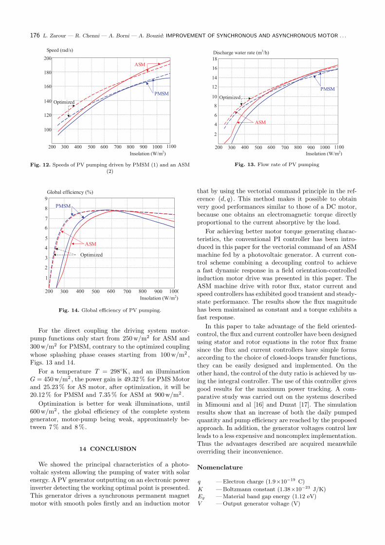
Fig. 12. Speeds of PV pumping driven by PMSM (1) and an ASM(2)
Fig. 13. Flow rate of PV pumping
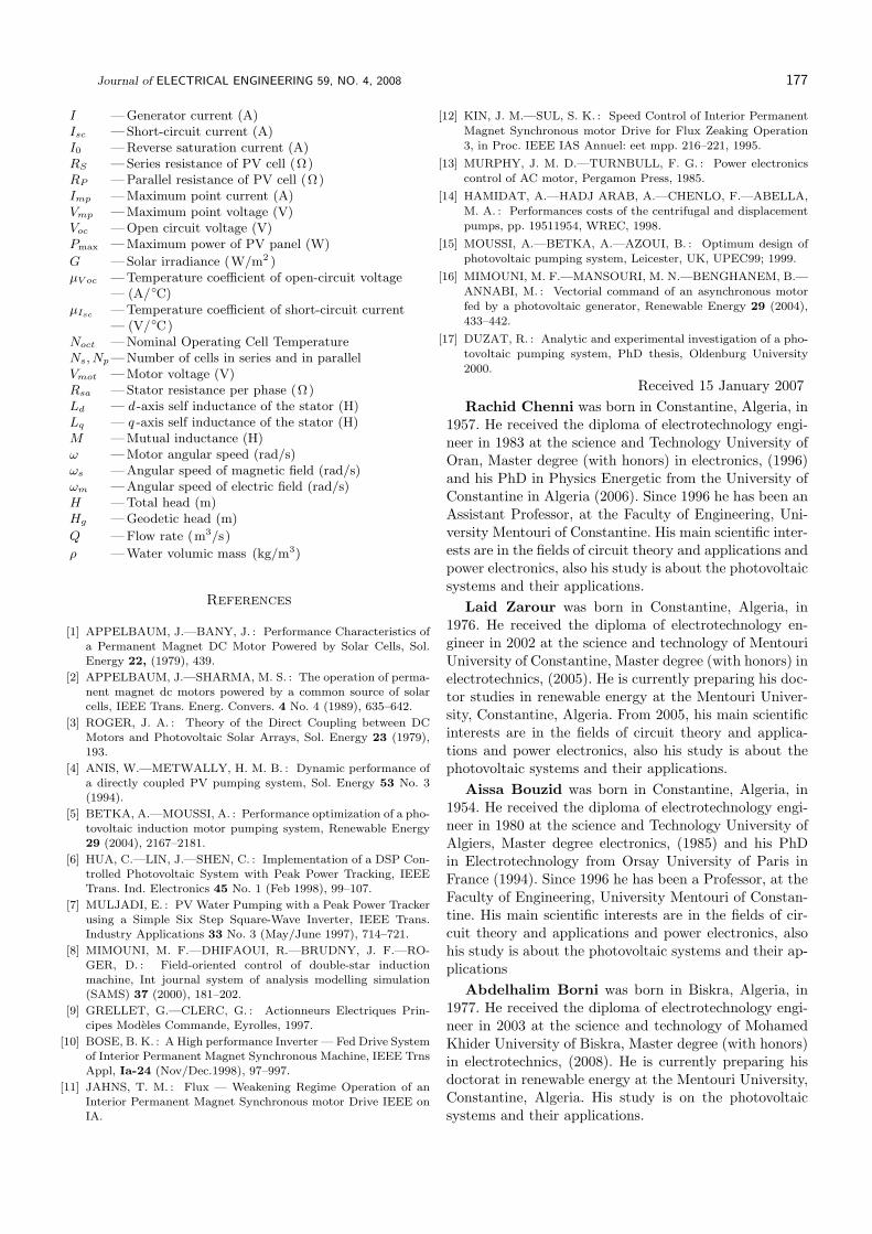
Fig. 14. Global efficiency of PV pumping.
For the direct coupling the driving system motor-pump functions only start from 250w/m2 for ASM and300w/m2 for PMSM, contrary to the optimized couplingwhose splashing phase ceases starting from 100w/m2 ,Figs. 13 and 14.
For a temperature T = 298K, and an illuminationG = 450w/m2 , the power gain is 49.32% for PMS Motorand 25.23% for AS motor, after optimization, it will be20.12% for PMSM and 7.35% for ASM at 900w/m2 .
Optimization is better for weak illuminations, until600w/m2 , the global efficiency of the complete systemgenerator, motor-pump being weak, approximately be-tween 7% and 8 %.
14 CONCLUSION
We showed the principal characteristics of a photo-voltaic system allowing the pumping of water with solarenergy. A PV generator outputting on an electronic powerinverter detecting the working optimal point is presented.This generator drives a synchronous permanent magnetmotor with smooth poles firstly and an induction motor
that by using the vectorial command principle in the ref-erence (d, q). This method makes it possible to obtainvery good performances similar to those of a DC motor,because one obtains an electromagnetic torque directlyproportional to the current absorptive by the load.
For achieving better motor torque generating charac-teristics, the conventional PI controller has been intro-duced in this paper for the vectorial command of an ASMmachine fed by a photovoltaic generator. A current con-trol scheme combining a decoupling control to achievea fast dynamic response in a field orientation-controlledinduction motor drive was presented in this paper. TheASM machine drive with rotor flux, stator current andspeed controllers has exhibited good transient and steady-state performance. The results show the flux magnitudehas been maintained as constant and a torque exhibits afast response.
In this paper to take advantage of the field oriented-control, the flux and current controller have been designedusing stator and rotor equations in the rotor flux framesince the flux and current controllers have simple formsaccording to the choice of closed-loops transfer functions,they can be easily designed and implemented. On theother hand, the control of the duty ratio is achieved by us-ing the integral controller. The use of this controller givesgood results for the maximum power tracking. A com-parative study was carried out on the systems describedin Mimouni and al [16] and Duzat [17]. The simulationresults show that an increase of both the daily pumpedquantity and pump efficiency are reached by the proposedapproach. In addition, the generator voltages control lawleads to a less expensive and noncomplex implementation.Thus the advantages described are acquired meanwhileoverriding their inconvenience.
Nomenclature
q —Electron charge (1.9×10⁻¹⁹ C)
K —Boltzmann constant (1.38×10⁻²³ J/K)Eg —Material band gap energy (1.12 eV)V —Output generator voltage (V)
Journal of ELECTRICAL ENGINEERING 59, NO. 4, 2008 177
I —Generator current (A)Isc —Short-circuit current (A)I0 —Reverse saturation current (A)RS —Series resistance of PV cell (Ω)RP —Parallel resistance of PV cell (Ω)Imp —Maximum point current (A)Vmp —Maximum point voltage (V)Voc —Open circuit voltage (V)Pmax —Maximum power of PV panel (W)
G —Solar irradiance (W/m2 )µV oc —Temperature coefficient of open-circuit voltage
— (A/C)µIsc —Temperature coefficient of short-circuit current
— (V/C)Noct —Nominal Operating Cell TemperatureNs, Np —Number of cells in series and in parallelVmot —Motor voltage (V)Rsa —Stator resistance per phase (Ω)Ld — d -axis self inductance of the stator (H)Lq — q -axis self inductance of the stator (H)M —Mutual inductance (H)ω —Motor angular speed (rad/s)ωs —Angular speed of magnetic field (rad/s)ωm —Angular speed of electric field (rad/s)H —Total head (m)Hg —Geodetic head (m)
Q —Flow rate (m3/s)
ρ —Water volumic mass (kg/m3)
References
[1] APPELBAUM, J.—BANY, J. : Performance Characteristics ofa Permanent Magnet DC Motor Powered by Solar Cells, Sol.Energy 22, (1979), 439.
[2] APPELBAUM, J.—SHARMA, M. S. : The operation of perma-nent magnet dc motors powered by a common source of solarcells, IEEE Trans. Energ. Convers. 4 No. 4 (1989), 635–642.
[3] ROGER, J. A. : Theory of the Direct Coupling between DCMotors and Photovoltaic Solar Arrays, Sol. Energy 23 (1979),193.
[4] ANIS, W.—METWALLY, H. M. B. : Dynamic performance ofa directly coupled PV pumping system, Sol. Energy 53 No. 3(1994).
[5] BETKA, A.—MOUSSI, A. : Performance optimization of a pho-tovoltaic induction motor pumping system, Renewable Energy29 (2004), 2167–2181.
[6] HUA, C.—LIN, J.—SHEN, C. : Implementation of a DSP Con-trolled Photovoltaic System with Peak Power Tracking, IEEETrans. Ind. Electronics 45 No. 1 (Feb 1998), 99–107.
[7] MULJADI, E. : PV Water Pumping with a Peak Power Trackerusing a Simple Six Step Square-Wave Inverter, IEEE Trans.Industry Applications 33 No. 3 (May/June 1997), 714–721.
[8] MIMOUNI, M. F.—DHIFAOUI, R.—BRUDNY, J. F.—RO-GER, D. : Field-oriented control of double-star inductionmachine, Int journal system of analysis modelling simulation(SAMS) 37 (2000), 181–202.
[9] GRELLET, G.—CLERC, G. : Actionneurs Electriques Prin-cipes Modeles Commande, Eyrolles, 1997.
[10] BOSE, B. K. : A High performance Inverter — Fed Drive Systemof Interior Permanent Magnet Synchronous Machine, IEEE TrnsAppl, Ia-24 (Nov/Dec.1998), 97–997.
[11] JAHNS, T. M. : Flux — Weakening Regime Operation of anInterior Permanent Magnet Synchronous motor Drive IEEE onIA.
[12] KIN, J. M.—SUL, S. K. : Speed Control of Interior Permanent
Magnet Synchronous motor Drive for Flux Zeaking Operation
3, in Proc. IEEE IAS Annuel: eet mpp. 216–221, 1995.
[13] MURPHY, J. M. D.—TURNBULL, F. G. : Power electronics
control of AC motor, Pergamon Press, 1985.
[14] HAMIDAT, A.—HADJ ARAB, A.—CHENLO, F.—ABELLA,
M. A. : Performances costs of the centrifugal and displacement
pumps, pp. 19511954, WREC, 1998.
[15] MOUSSI, A.—BETKA, A.—AZOUI, B. : Optimum design of
photovoltaic pumping system, Leicester, UK, UPEC99; 1999.
[16] MIMOUNI, M. F.—MANSOURI, M. N.—BENGHANEM, B.—
ANNABI, M. : Vectorial command of an asynchronous motor
fed by a photovoltaic generator, Renewable Energy 29 (2004),
433–442.
[17] DUZAT, R. : Analytic and experimental investigation of a pho-
tovoltaic pumping system, PhD thesis, Oldenburg University
2000.
Received 15 January 2007Rachid Chenni was born in Constantine, Algeria, in
1957. He received the diploma of electrotechnology engi-neer in 1983 at the science and Technology University ofOran, Master degree (with honors) in electronics, (1996)and his PhD in Physics Energetic from the University ofConstantine in Algeria (2006). Since 1996 he has been anAssistant Professor, at the Faculty of Engineering, Uni-versity Mentouri of Constantine. His main scientific inter-ests are in the fields of circuit theory and applications andpower electronics, also his study is about the photovoltaicsystems and their applications.
Laid Zarour was born in Constantine, Algeria, in1976. He received the diploma of electrotechnology en-gineer in 2002 at the science and technology of MentouriUniversity of Constantine, Master degree (with honors) inelectrotechnics, (2005). He is currently preparing his doc-tor studies in renewable energy at the Mentouri Univer-sity, Constantine, Algeria. From 2005, his main scientificinterests are in the fields of circuit theory and applica-tions and power electronics, also his study is about thephotovoltaic systems and their applications.
Aissa Bouzid was born in Constantine, Algeria, in1954. He received the diploma of electrotechnology engi-neer in 1980 at the science and Technology University ofAlgiers, Master degree electronics, (1985) and his PhDin Electrotechnology from Orsay University of Paris inFrance (1994). Since 1996 he has been a Professor, at theFaculty of Engineering, University Mentouri of Constan-tine. His main scientific interests are in the fields of cir-cuit theory and applications and power electronics, alsohis study is about the photovoltaic systems and their ap-plications
Abdelhalim Borni was born in Biskra, Algeria, in1977. He received the diploma of electrotechnology engi-neer in 2003 at the science and technology of MohamedKhider University of Biskra, Master degree (with honors)in electrotechnics, (2008). He is currently preparing hisdoctorat in renewable energy at the Mentouri University,Constantine, Algeria. His study is on the photovoltaicsystems and their applications.