improvement of water recycling system for …
TRANSCRIPT

IMPROVEMENT OF WATER RECYCLING SYSTEM FOR
MOTORHOMES
Bachelor’s thesis
Riihimäki, Mechanical Engineering and Production Technology
Autumn 2020
Ekaterina Alifanova

ABSTRACT Mechanical Engineering and Production Technology Riihimäki Author Ekaterina Alifanova Year 2020 Title Improvement of water recycling system for motorhomes Supervisor(s) Tapio Väisänen
ABSTRACT
A van that has most of home facilities is called a motorhome. It enables people to travel anywhere since they can live inside the car. However, the water tank needs to be refilled occasionally as well as wastewater must be disposed. This leads to significant limitations in the travelling experience. Quantum Engineering Oy has developed a working prototype for a water-purification system that recycles wastewater and eliminates unnecessary refills and disposal. However, it turned out that their current version of prototype was not able to separate water from soap and therefore reusing the water became impossible: it remained soapy. The aim of this thesis project was to modify the water-purification system with the main objective of finding a way to separate water from soap. In order to prove the concept, building and testing the prototype was required. Principles of electrocoagulation (EC) were used in this work. Electrocoagulation is a method of water purification by applying an electric current through metal electrodes that are in contact with the contaminated water. The electric field leads to a release of the hydrolyzed electrode’s ions that form coagulants which remove the soap particles from the water and guarantee success of flocculation. A working prototype was developed after several iterations. The prototype successfully removed different types of detergents, and the purified water could be reused for everyday purposes after filtration. The technology developed in this work has been patented by Quantum Engineering Oy. Although, the prototype was successful, further improvement can be achieved by automating removal of foam and sediment, cleaning the electrodes as well as choosing the optimal parameters for the EC unit.
Avainsanat Electrocoagulation, motorhome, recycling Sivut 42 pages
CONTENTS
1. INTRODUCTION AND THEORY ..................................................................................... 1
1.1 Background .......................................................................................................... 1
1.2 Scope and objectives ........................................................................................... 4
1.3 Mixture of water and soap .................................................................................. 5
2. IDEATION ..................................................................................................................... 7
2.1 Ideation method – TRIZ ....................................................................................... 7
2.1.1 Selection of idea ...................................................................................... 8
2.1.2 Distillation ................................................................................................ 8
2.1.3 Reverse osmosis .................................................................................... 10
2.1.4 Electrocoagulation ................................................................................. 12
2.2 Ranking of ideas ................................................................................................ 14
2.3 Principles of electrocoagulation ........................................................................ 16
2.3.1 Electrocoagulation in practice ............................................................... 16
2.3.2 System set-up ........................................................................................ 17
3. PROTOTYPING ............................................................................................................ 21
3.1 Prototype 1 ........................................................................................................ 21
3.1.1 Aim ......................................................................................................... 21
3.1.2 Set-up..................................................................................................... 21
3.1.3 Experiment plan .................................................................................... 25
3.1.4 Experiment results ................................................................................. 26
3.1.5 Discussion .............................................................................................. 28
3.2 Prototype 2 ........................................................................................................ 30
3.2.1 Aim ......................................................................................................... 30
3.2.2 Set-up..................................................................................................... 30
3.2.3 Microscope inspection .......................................................................... 34
3.2.4 Discussion .............................................................................................. 36
4. CONCLUSIONS AND RECOMMENDATIONS FOR FUTURE RESEARCH ........................ 38
REFERENCES .................................................................................................................... 39

1
1. INTRODUCTION AND THEORY
1.1 Background
In the modern world travelling has become one of the most important aspects of people’s life. Tourist industry is constantly growing, offering cheaper and more comfortable ways of exploring the new lands. Motorhome, an example of which is shown in Figure 1, is an almost ideal option for frequent travellers since it gives them an opportunity to live on the road.
Figure 1. An example of motorhome (Favpng n.d.)
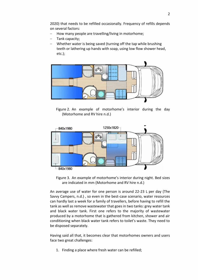
A motorhome is a type of a recreational vehicle and as its name implies, it has a “motor”, the vehicle’s engine, along with living accommodation, “home”, meaning there are typically several beds called berths, toilet and shower, kitchen utilities as a sink, a stove, an oven, a fridge, etc. More luxurious versions of motorhomes can offer a TV, a dishwasher, a microwave, air conditioning, etc. Usually, interiors of such vehicles look different during day and night. The reason behind it is smart storage solution – some berths are foldable. An example of a motorhome’s interior during the day is shown in Figure 2 and during the night in Figure 3. With these conditions, it is easy to be on the road for a long time, making stops anywhere without having to book a hotel or just live inside of it without driving. However, in comparison with a house or an apartment, water needed for kitchen and showering necessities is strictly limited. Depending on the manufacturer and the class of the RV, a motorhome usually has a tank of fresh water from 70 L to 375 L in volume (Yoganand,
2
2020) that needs to be refilled occasionally. Frequency of refills depends on several factors:
− How many people are travelling/living in motorhome;
− Tank capacity;
− Whether water is being saved (turning off the tap while brushing teeth or lathering up hands with soap, using low flow shower head, etc.);
Figure 2. An example of motorhome’s interior during the day (Motorhome and RV hire n.d.)
Figure 3. An example of motorhome’s interior during night. Bed sizes are indicated in mm (Motorhome and RV hire n.d.)
An average use of water for one person is around 22-23 L per day (The Savvy Campers, n.d.) , so even in the best-case scenario, water resources can hardly last a week for a family of travellers, before having to refill the tank as well as remove wastewater that goes in two tanks: grey water tank and black water tank. First one refers to the majority of wastewater produced by a motorhome that is gathered from kitchen, shower and air conditioning when black water tank refers to toilet’s waste. They need to be disposed separately. Having said all that, it becomes clear that motorhomes owners and users face two great challenges:
1. Finding a place where fresh water can be refilled;

3
2. Finding a dumping station where grey and black water tanks can be emptied.
Travelling then will be refined by these stops, making it impossible to leave far out of the civilization’s reach. An ideal solution for this problem would be recycling grey water as that would eliminate the need for unnecessary refilling and disposal, leaving only the black water tank in need of cleaning. And that can be significantly less frequent. Quantum Engineering Oy has developed a system shown in Figure 4 that is able to cleanse wastewater produced by motorhomes. It allows people to travel as far as they want without worrying about refilling water for everyday use.
Figure 4. Quantum Engineering’s water-recycling system
The principle behind this is shown in Figure 5: air conditioning absorbs moist from the surrounding air and leads condensed water to the reservoir tank where grey water from kitchen and shower is also being collected. The water reservoir tank is filled with glass wool that is typically used within swimming pools filters. This acts as a coarse filter and home for bacteria which break apart food waste. A UV source on the top of the tank is responsible for killing the bacteria still left in the water. Grey water is then pumped through three stages of activated carbon filters: a 50-micron, 20-micron and 5-micron carbon filters respectively. The result of the filtration now goes back to the freshwater system: kitchen and shower.

4
Figure 5. Schematic image of current water-recycling system
There are several impurities that can be found in the wastewater produced by using motorhomes. For example, such impurities include food waste, human waste, oil, soap and detergents, etc. The filtration system described above can successfully deal with the most common contaminants met in everyday life except soap.
1.2 Scope and objectives
The aim of this thesis project was to find a suitable method to separate soap from water and to implement it into the already existing system with a minimum amount of changes. This included:
− Thorough research of the relation of water and soap;
− Ideation;
− Building and testing a working prototype; There were only two requirements that had to be taken into account:

5
− An improved version of the system needed to fit into the motorhome’s section for it that was equal to 1 cubic meter;
− The system unit of water-purification from soap had to be mechanical.
1.3 Mixture of water and soap
In order to understand the relationship between water and soap, it was needed to investigate the chemical background of this mixture. It is well-known that water does not mix with oil because oil’s molecules are hydrophobic (from ancient Greek where “hydro” means “water” and “phobic” means “fearing”) and therefore push water molecules away. At the same time water molecules are strongly attracted to each other due to their polarity, or in other words adsorbed very tightly. Soap can mix with both water and oil and that can be explained with its chemical formula written below.
СН3—(CH2)n—COONa (1) This formula can be divided in two groups: [СН3—(CH2)n] and [COONa]. The first group is hydrophobic that cannot mix with the water on the molecular level but does mix with non-polar compounds like oil and grease. It is usually called the hydrophobic tail. On the other hand, [COONa] is hydrophilic (from ancient Greek where “hydro” means “water” and “philic” means “loving”) that is attracted to water, mixes with polar compounds and is usually called hydrophilic head. When in contact with water, soap acts as a surfactant i.e. reducing the surface tension and its molecules form little bubbles called micelles. As it is shown in Figure 6, the exterior surface is formed by the arrangement of hydrophilic heads while the hydrophobic tails tend to move inside towards the oil or any other non-polar compound.

6
Figure 6. Formation of the micelle (University of Waikato 2012)
Therefore, anything inside of the micelle is trapped and does not come into direct contact with water. And as the dirty water is being washed away, all the micelles with dirt, oil or grease go along with it. Almost all detergents that are based on surface-active substances act under the same scenario when in contact with water. Now it becomes obvious that wastewater from motorhomes contains millions of soap micelles with dirt among other impurities. When it goes through the current filtration system, the micelles are broken, and dirt is successfully removed but the hydrophilic heads of soap molecules [COONa] are still pointing towards water molecules. It is now needed to figure out a way for molecules to detach from each other.

7
2. IDEATION
2.1 Ideation method – TRIZ
Since the problem in this project was narrowed down to a particular soap compound that does not want to let go of water molecules, it was now much easier to look for a solution. However, there were many ideation methods available such as brainstorming, storyboarding, analogy thinking, opposite thinking, TRIZ, etc. For this work TRIZ was selected as the most appropriate and the best working tool due to its practical algorithms, strong scientific background and highly successful worldwide usage. There is a list of some companies using TRIZ shown in Figure 7.
Figure 7. Some of the companies using TRIZ
TRIZ («теория решения изобретательских задач», translated from Russian language as “the theory of the resolution of invention-related tasks” or as it is most commonly referred to “the theory of inventive problem solving”) is a powerful problem-solving tool developed by a Soviet inventor Genrich Altshuller based on the idea of pattern of inventions (Mind Tools, n.d.). No problem is new and the only thing that changes is the appearance of a problem. The basic principle behind TRIZ method shown in Figure 8 is that for every current problem there is a general form of that problem that someone else had encountered before and solved. So, with an already existing solution the only thing left to do is to figure out how to apply it to your own problem.

8
Figure 8. Simple graph of TRIZ principle
After thorough search it became clear that many industries have indeed faced similar difficulties with recycling water and, in particular, getting rid of soap – for example, in sewage systems, spaceships, cooling towers, private cleaning companies, etc. Typically, the solution for wastewater treatment is either chemical: chemical coagulation, chemical oxidation, ion-exchange, etc. or mechanical: filtration, air stripping, reverse osmosis, electrocoagulation, distillation, etc. or more often a combination of mentioned above. However, not all of these would be suitable for the current problem. In this work, only mechanical solutions were considered.
2.1.1 Selection of idea
Out of all the potential solutions listed above, only three of the most promising mechanical-based methods were studied further:
− Distillation;
− Reverse osmosis;
− Electrocoagulation.
2.1.2 Distillation
Distillation is one of the oldest methods of water-purification known to the mankind. The first mentioning of this process related to drinkable water preserved to this day was made by the Peripatetic philosopher called Alexander of Aphrodisias who described how it is possible to turn sea-water into drinking water by selective boiling and condensation. (Kalogirou, 2005, p. 246). Since then it has been developed and even today is being actively applied in various industries like alcohol and perfume production, petroleum refineries, petrochemical and chemical plants, pharmaceutical research, etc (Maxfield, 2018). Distillation illustrated in Figure 9 is a method of separating a pure substance from a mixture of components by using a heat source, although,

9
it is possible only when they have different boiling points. It works in a way that a mixture is being heated until one of the compound elements reaches its boiling point and therefore starts to vaporize. The temperature is being kept stable at the boiling point of the evaporating substance to maintain the process. The newly formed steam goes through a condenser where it cools down and is formed into a substantially pure gas/liquid on its way to a final/receiving container. The rest of the elements that have higher boiling point remain in the original container.
Figure 9. The process of distillation (Advance Water Solutions 2017)
Although, the distillation can be used for various gases and liquids, our interest lay particularly in the separation of water from its impurities, and especially soap. There is no doubt that distillation of water is extremely effective in removing bacteria, viruses, several dangerous heavy metals like lead, arsenic, and mercury as well as salt and other natural contaminants but it cannot deal with many synthetic chemicals such as pesticides, herbicides, and chlorine solutions because their boiling point is lower than boiling point of water (Kalogirou, 2005, p. 273). Also, it deprives water of soluble minerals like calcium, magnesium, and phosphorous. When they are removed, water becomes very acidic and will need additional processing before it can be used again (History of Water Filters, n.d.). Moreover, the distillation process cannot guarantee a complete separation between water and other materials, most often it results in partial separation that increases the concentration of the selected components of the mixture, and for this reason it is often repeated several times with the treated water which brings severe losses (History of Water Filters, n.d.). In summary, the pros and cons of this method are highlighted in Table 1 presented below.

10
Table 1. Summary of distillation
Pros Cons
Distillation removes bacteria, viruses, heavy metals, salt, etc.
Distillation cannot separate water from many synthetic chemicals.
Theoretically this method can separate water from soap.
Distillation strips water of soluble minerals what makes it very acidic and will need additional resources and treatment.
Severe losses are present since distillation has to be repeated several times.
Distillation requires a heat source & its maintenance.
Distillation is a time-consuming process.
2.1.3 Reverse osmosis
Reverse osmosis is one of the most common wastewater treatment methods that has originally been used for the desalination of seawater, just like distillation. Today it is being used for purification of ground and surface fresh water (Belkacem, Bekhti & Bensadok, 2007, p.101; Perez-Gonzalez, Urtiaga, Ibanez, & Ortiz, 2012, p.267). State by forcing it through a semipermeable membrane to remove ions, molecules, and larger particles. In order to understand how reverse osmosis works, the principle of osmosis needs to be explained. Osmosis illustrated in Figure 10 works in a way that there are two mixtures with different concentration of salt, or any other solute separated by a semipermeable membrane through which water flows from the lower to the higher concentration solution, until they become equal in their concentration. Reverse osmosis illustrated in Figure 11 does the opposite by applying pressure to the natural movement of water, forcing it to flow through the membrane from the higher to the lower concentration. Mixed solution is held on the pressurized side of the membrane while the pure solvent flows to the other side. This process is able to remove many types of dissolved and suspended elements from water and is effectively used in both industrial processes and the production of drinking water (Mesogeos, n.d.). The most important part of reverse osmosis treatment is the semipermeable membrane because it is responsible for the selection of what is going through it and what stays on the other side. Generally, such membranes are constructed from polyamide-based materials which

11
contain tiny pores through which water can pass through easily (Woo, Kim, Shon, & Tijing, 2019, p.xxx).
Figure 10. Osmosis process (Hillewaert 2011)
Figure 11. Reverse osmosis (Angel Water n.d.)
They are also able to block way for large ions and molecules, for example, molecules of salt or other organic compounds and natural minerals as well as bacteria and disease-causing pathogens but fail to stop chemical attacks from chlorine, pesticides, herbicides, that are molecularly smaller than water (Woo et al., 2019, p. xxxi). So, as it was in the case of distillation, purified water would be stripped of natural trace elements, again making

12
the water very acidic that will require additional treatment before it can be used again. Unfortunately, the reverse osmosis process contains more downsides which make it an ineffective solution for this case. Depending upon the hardness of the water involved, sedimentation of calcium or magnesium ions is likely to occur on the membrane (Perez-Gonzalez et al., 2012, p. 272). If the concentration of the calcium or magnesium in the water is at a high enough level, it will create a hard mineral on the inside of the membrane, making it inefficient and practically useless. In addition, reverse osmosis technology wastes a large portion of the water that flows through it. Usually, it wastes 3-4 litres of water for every litre it purifies (PSI Filters, n.d.). Another downside is that this process is incredibly slow when compared to other water treatment alternatives. In summary, the pros and cons of this method are highlighted in Table 2 below.
Table 2. Summary of reverse osmosis
Pros Cons
Reverse osmosis is very successful in removing salts and disease-causing pathogens.
Reverse osmosis cannot separate water from many synthetic chemicals.
Severe losses are present.
Reverse osmosis is a very slow process.
Sedimentation may occur on the membrane if water involved is hard.
Reverse osmosis strips water from natural trace elements, making the water very acidic that will need additional treatment before it can be used again.
2.1.4 Electrocoagulation
One of the most advanced and modern techniques is the electrocoagulation (EC) process also known as short-wave electrolysis or radio frequency diathermy. It was first implemented in the 1880s when chemical engineer William Webster introduced an electrolytic system for wastewater treatment where a weak current was passed through iron plates in the London’s sewage, for which he was awarded US patent on 19 February 1889 (Webster, 1889). Although, at that period of time, this method was less successful than other available sewage treatment technology.

13
In 1909, J.T. Harries described the "Electronic Coagulator" with aluminium and iron anodes that were electrochemically dissolved into reaction solution that interacted with hydroxyl ions produced by cathodes to form aluminium hydroxide (Cirak, 2018). The hydroxides flocculated and dissolved suspended substances by purifying contaminated water. He also received US patent for it. Since then, the application of electrocoagulation has been significantly expanded and it is currently being used in wash water treatment, wastewater treatment, industrial processed water, and medical treatment, etc. (Kuokkanen, Kuokkanen, Rämö & Lassi, 2013, p. 89). It even replaces some of the traditional treatment processes such as filtration, chemical treatment, etc. which have proved to be less effective and more expensive processes. (Kuokkanen et al., 2013, p. 89). Electrocoagulation’s success is also due to its ability to remove generally more difficult contaminants, for example, emulsified oil, total petroleum hydrocarbons, refractory organics, suspended solids and heavy metals. Electrocoagulation is performed by passing a minimal electric charge across metal electrodes that are submerged into the wastewater. When electricity passes through electrodes, several electrolytic reactions take place: metal ions are released from the sacrificial anode and combined with hydroxide ions produced at the cathode where also hydrogen bubbles evolve. This results in the formation of polymeric metal hydroxides, which are excellent coagulants. These coagulants trap and remove contaminants that are present in the polluted water. This principle is illustrated in Figure 12.
Figure 12. Electrocoagulation (Fayad, 2017)

14
EC requires simple equipment and can be designed in any size. It is cost effective and easily operable. The main electrocoagulation consumables are electric power and metallic electrodes. EC’s largest downside is passivation if the electricity is coming from a DC source (Vasudevan, Lakshmi, & Sozhan, 2011, p.26). During the electrocoagulation process, electrodes become coated with a non-conducting oxide, particularly when processing contaminated water with high concentrations of scaling compounds and dissolved solids. Therefore, electrocoagulation’s efficiency reduces, power consumption rises and time-consuming maintenance to manually clean, acid wash or replace electrode plates becomes necessary. In summary, the pros and cons of this method are highlighted in Table 3 below.
Table 3. Summary of electrocoagulation
Pros Cons
Low operating costs and power requirements.
Sacrificial electrodes wear out due to oxidation and therefore should be changed once in a while.
Electrocoagulation removes suspended and colloidal solids as well as fats, oil, and grease ad complex organics.
High conductivity of the wastewater suspension is required.
Electrocoagulation destroys and removes bacteria, viruses and cysts.
An impermeable oxide membrane may be formed on the cathode which can result in loss of efficiency of the EC unit.
Electrocoagulation breaks oil emulsions in water.
EC unit is designable for any size and need.
EC unit requires low maintenance.
2.2 Ranking of ideas
The ranking of ideas was measured from 1 (very bad) to 5 (very good) based on the following criteria:
− Cost;
− Integration;
− Maintenance;
− Ease of operation;
− Time consumption; Even though, there was no specific limitation on cost, it was obvious that the least expensive option that satisfied every other need was preferred.

15
As it was mentioned before, both distillation and reverse osmosis strip water of natural trace elements what makes it very acidic as well as both of them cannot separate water from many synthetic chemicals. Solving that would require additional resources and treatment which would rise the cost of these methods. It must be noted that installation of distillation equipment would be the most expensive out of all due to the complexity of the system. Also, in reverse osmosis there is a risk of sedimentation on the membrane that can make it completely useless and it would have to be changed, increasing the cost again. On the other hand, the cost of electrocoagulation system includes only the installation and periodical change of electrodes. In terms of integration to the current filtration system described in Chapter 1, reverse osmosis and electrocoagulation had the same rating. Both of them could fit in nicely and would not exceed the size limitation. However, the distillation process would have a much more complex system that would require bigger space and therefore would be harder to install in the available space. Once electrocoagulation system is installed, it requires a very low level of maintenance – only the change of electrodes if DC current is being used and, perhaps, occasional cleaning. Reverse osmosis requires a little bit more special maintenance for the membrane change if it gets blocked and also refills of water due to severe losses during the process itself. Distillation would need water refills due to losses as well and more frequent check-ups because of the system’s vulnerability and complexity. All the potential ideas should be easy enough to operate since the final system would be automated and would not require constant supervising. Operation time covered here the complete time required of wastewater treatment before it could be reused. Distillation and reverse osmosis do not guarantee complete water purification from the first run, making them much more time-consuming than electrocoagulation. Based on the above arguments, the ranking of these methods was given as shown in Table 4.
Table 4. Comparison of different methods to clean water from soap
Method Cost Integration
Maintenance
Ease of operation
Operation time
Total
Distillation 1 3 2 5 3 13
Reverse Osmosis
2 5 3 5 3 18
Electrocoagulation
4 5 4 5 5 23

16
In conclusion, electrocoagulation had the highest amount of points between three potential methods and seemed to be the most promising and practical solution.
2.3 Principles of electrocoagulation
2.3.1 Electrocoagulation in practice
Electrocoagulation is the method of water-purification by applying electric current through metal electrodes that are in contact with contaminated water. The basic mechanism behind this process is illustrated in figure 13. As it can be seen, there are three major stages involved in electrocoagulation: dissolution, coagulation and flocculation. During the first stage, metal ions (Me+) are released from the sacrificial anode while hydroxide ions (OH-) are simultaneously produced at the cathode where also hydrogen gas bubbles (H2) evolve. In coagulation stage, metal ions combine with hydroxide ions to create polymeric metal hydroxides that are also known as coagulants. During the last stage called flocculation, polymeric hydroxides trap and remove contaminants such as dissolved metals, suspended solids, and emulsified oils that are present in the polluted water.
Figure 13. Electrocoagulation (Water Tectonics n.d.)
Most common applications of electrocoagulation method include:
− Sewage treatment;
− Process rinse water and wash water;
− Ground water clean-up;
− Surface water clean-up;

17
− Cooling towers;
− Water pre-treatment.
2.3.2 System set-up
Although, size and configuration of the electrocoagulation cells may vary from case to case, the main electrocoagulation consumables are power and electrodes. Typically, for power the direct current is being used and for electrodes there are two most common and proven to be effective materials – aluminium and iron (Akanksha, Roopashree & Lokesh, 2014, p.519). These systems are typically constructed of plate electrodes that are immersed into water. Based on the way of the connection of electrodes to the power supply, they can be monopolar as shown in the example in Figure 14 or bipolar. There are several methods of how they can be arranged in the EC system which are mentioned below.
Figure 14. Example of EC monopolar system set-up (Taghizadeh, 2015)
It must be noted that not all water contaminants can be removed at the same time and with the same operating conditions. To meet some of the removal objectives, a multi-stage electrocoagulation set-up might be required, where each stage would have their own specific operating conditions. Moreover, EC system setup must allow access to the electrodes when there is a need to change or clean them.
2.3.2.1 Electrodes
Most often, sacrificial electrodes are conductive metal plates, however, a variety of anode and cathode geometries has been used in the past, for instance, rods, tubes, plates with holes, balls, fluidized bed spheres, wire

18
mesh, etc. Electrode’s size highly depends on the general idea behind the set-up, although, it is generally as big as the tank allows it to be. The material of the electrode defines the electrochemical reactions that take place in the EC cell and how well they go. Some suitable materials for the EC set-up include aluminium, iron, stainless steel and titanium or a combination of these. Also, it is possible to use a series of reaction chambers with different electrode materials. In this work, only aluminium and iron were considered for the prototype due to their availability and proof of efficiency. While it is possible to use both or a combination of them, aluminium electrodes are more expensive and will wear down faster. At the same time there is an argument if iron dissolves as Fe (II) or Fe (III) and it is a question of great significance because Fe (II) is a poor coagulant. Aluminium, on the other hand, always dissolves as Al (III) and gives great results during coagulation and flocculation. In general, aluminium is considered to be superior to iron in the EC process (Vepsäläinen, 2012, pp. 27-28).
2.3.2.2 Electricity
Usually, direct current (DC) is used in EC processes, however, oxidation may cause corrosion formation on the anode and an impermeable oxide layer on the cathode. (Vasudevan et al., 2011, p.26). That makes current motion ineffective and the efficiency of the electrocoagulation process diminishes. Using alternating current (AC) may reduce the formation of the oxide layer on the cathode. Electrodes in the EC cell can be connected in three ways that are shown in Figure 15: a) monopolar electrodes on parallel connection; b) monopolar electrodes in series connection; c) bipolar electrodes in series connection. In Figure 15. (a), it is seen that all anodes are connected to each other and to the positive pole of power source while all cathodes are also connected to each other and to the negative pole of power source. The electric current, as in any parallel connection, is split up between all the electrodes depending on their individual resistance.

19
Figure 15. Possible electrode connections (Garcia-Seguraa, Eibanda, Vieira de Meloa & Martínez-Huitlea, 2017)
In Figure 15. (b), it is seen that outer electrodes are connected to the power source but have no interconnection with the electrodes in between of them. The electrodes in-between are connected in pairs – cathodes to anodes. The same current is being transferred through all electrodes. In Figure 15. (c) it is seen that in the bipolar system outermost electrodes are, in fact, monopolar and only they are connected to the power source. There is no interconnection between them and electrodes in-between. When current passes through monopolar electrodes, sacrificial electrodes are being polarised. Side of the electrode facing the cathode is positively polarised and side facing anode is negatively polarized.
2.3.2.3 Reaction time
Some of the most essential factors affecting the reaction time are:
− pH of water;
− volume of polluted water;
− level of contamination;
− volume of EC cell;
− material of electrodes, number of electrodes, type of their connection, distance in-between electrodes, thickness of electrodes;
− temperature,
− others. In this work these factors were omitted, since it would be practically impossible to estimate the reaction time in motorhomes due to the nature of the interconnection between the affecting factors.

20
2.3.2.4 Maintenance
Electrocoagulation systems are rather simple to operate and maintain, however if DC is being used, sacrificial electrodes need to be changed more often than in case with AC due to the formation of an impermeable oxide layer on the cathode and corrosion formation on the anode. Frequency of electrodes’ replacement also depends on frequency of using of EC system and level of pollution in treated water. During flocculation soapy foam is being formed in EC cell, so after completing the process it has to be removed either manually or by an automated system.
2.3.2.5 Cost
Electrocoagulation technology only requires power source and electrodes’ replacement once in a while. Since motorhome already has electricity, the major expenses come from installation and electrodes’ change that can be counted in tens of euros.

21
3. PROTOTYPING
After coming to the conclusion that electrocoagulation was the most reasonable solution to the given problem, this had to be proven by testing. Two prototypes were built during this work and their differences are discussed further here.
3.1 Prototype 1
3.1.1 Aim
The aim of prototype 1 was to prove the concept of electrocoagulation to remove soap from water. Efficiency and selection of optimal value of parameters is not of primary importance. Different soaps and detergents were used in the laboratory conditions to evaluate the operation time and its effectiveness. Also, the effect of different voltage levels was investigated.
3.1.2 Set-up
Since the role of this prototype was to see the electrocoagulation’s performance, a simple device was built and used in the conducted tests. The device consisted of a plastic tank with a tap where electrodes connected by copper wires to the power source could be emerged as shown in Figure 16.
Figure 16. Prototype 1

22
3.1.2.1 Container
A container as illustrated in Figure 17 was chosen medium size, so it would be possible to carry or move it if the experiment needed to be relocated or shown someplace else. The size of the tank was 340 x 250 x 160 mm which is equal to a volume of 8 L. It was made from plastic and was transparent, so that in-situ observation of the reaction process was possible. The container also had a tap near the bottom, so water samples could be drawn when the test was done.
Figure 17. Plastic container used in prototype 1
3.1.2.2 Electrodes
For electrodes, aluminium was a material of choice since it is always dissolved as Al (III) which is better for flocculation and coagulation than iron’s Fe (II) or Fe (III) as it was mentioned in Chapter 2. To make the electrocoagulation process go as fast and efficient as possible, it was decided to increase the surface area of electrodes by using regular plates and take up all the available space. As a result, there were 21 aluminium plates with the size of 260 x 100 x 3 mm and the distance between them was about 4 mm. They were isolated from each other by rubber blisters. Compound of electrodes was chosen to be monopolar in parallel connection since a low potential difference is needed as compared with serial connections. Wires linking anodes from one side and cathodes from another were then grouped by the simplest terminal connectors shown in Figure 18 and passed to the negative and positive poles respectively.

23
Figure 18. Terminal connectors in prototype 1
3.1.2.3 Electricity source
In order to supply electricity to electrodes and water, Velleman 0-30V 2.5A DC power supply shown in Figure 19 was used. It was chosen due to its availability at the laboratory. Wires used to connect electrodes to power source were made of copper, each of 2 mm thickness isolated by rubber cover.

24
Figure 19. Power supply that was used in tests with prototype 1
3.1.2.4 Test solution
Tap water under room temperature was mixed with different detergents, for example, with soap bar, liquid soap, washing powder shown in Figure 20 or dishwasher liquid to create test solutions. It was thought that in motorhome’s wastewater tank there would be a combination of different detergents and dirt, so it was needed to try several most common types. Since original filtration system successfully removed the most common contaminants met in everyday life except for soap, following electrocoagulation tests were aimed only at removing detergents.
Figure 20. Water mixed with washing powder
The volume of container was 8 L, however, test solutions did not exceed 5 L because electrodes took up the rest of the space. On average, the volume of treated water was equal to 4.75 L. Since it was the first iteration, the ratio of water to detergent was much higher than could be in typical everyday family usage. Some of the tests had up to 200 ml of detergent for 4.75 L of water. It is obvious that such proportion would never meet in real life, but the goal of the experiment was to see if electrocoagulation can work in these extreme conditions. Ratios of detergent to water in different test solutions used in prototype 1 are presented in Table 5.

25
Table 5. Test solution types based on water to detergent ratio used in prototype 1
Solution Water Detergent Ratio of detergent/water
A1 Tap water Liquid soap 0.1/4.75 (0.021)
A2 Tap water Liquid soap 0.05/4.75 (0.01)
A3 Tap water Liquid soap 0.025/4.75 (0.005)
A4 Tap water Liquid soap 0.015/4.75 (0.003)
B Tap water Soap bar -
C1 Tap water Washing powder 0.05/4.75 (0.001)
C2 Tap water Washing powder 0.025/4.75 (0.005)
D1 Tap water Dishwasher liquid 0.2/4.75 (0.042)
D2 Tap water Dishwasher liquid 0.1/4.75 (0.021)
D3 Tap water Dishwasher liquid 0.05/4.75 (0.01)
D4 Tap water Dishwasher liquid 0.025/4.75 (0.005)
D5 Tap water Dishwasher liquid 0.015/4.75 (0.003)
There is no ratio with soap bar shown in the table because it was simply rubbed into the water and thus it would be practically impossible to estimate how much of it was dissolved.
3.1.3 Experiment plan
It was needed to see if electrocoagulation manages to separate soap from water and how well it works with various detergents in different ratios. Experiment procedure followed is presented in Figure 21. Transparency of water is a sound indication that electrocoagulation process successfully separated soap from water and the test can be stopped. It can be seen in Figures 20 and 22 that water mixed with detergents changes its colour. Cleanliness test includes smelling the water, touching it in order to make sure the water is not soapy and visually inspecting it.

26
Figure 21. Experiment procedure
Figure 22. Liquid soap mixed with water
3.1.4 Experiment results
Experiment results are summarized in the tables 6 and 7 where Table 6 represents the best outcome and Table 7 represents the worst one. Cleanliness was ranked on a scale from 0 to 10, where 0 was not clean, 5 somewhat clean and 10 completely clean.

27
In all the tests current was set to maximum that power’s supply could provide (2.5 A), but since conductivity of water changed during experiment, current and voltage also changed. Therefore, current was manually held at 2-2.5 A throughout each test. Also, it must be noted that in tests with soap bar different amounts of soap were used, although it was practically impossible to estimate the exact quantities.
Table 6. Best results of EC tests
Solution Lowest voltage
Maximum voltage
Average voltage
Time Cleanliness
A1 1.42 V 4.13 V 2.78 V 10 h 6
A1 1.61 V 4.53 V 3.07 V 10 h 30 min 6
A2 2.11 V 5.97 V 4.04 V 9 h 7
A2 2.19 V 6.15 V 4.17 V 8 h 10 min 6
A3 2.29 V 7.33 V 4.81 V 7 h 7
A3 2.32 V 7.54 V 4.93 V 6 h 7
A4 5.51 V 9.8 V 7.66 V 6 h 7
A4 6.3 V 9.66 V 7.98 V 5 h 20 min 7
B 2.16 V 5.08 V 3.62 V 4 h 8
B 1.5 V 4.6 V 3.05 V 7 h 8
B 2.1 V 6.1 V 4.1 V 6 h 10 min 8
D1 1.5 V 5.71 V 3.61 V 12 h 6
D2 1.8 V 4.99 V 3.4 V 10 h 7
D3 2.63 V 7.11 V 4.87 V 8 h 7
D3 2.1 V 8.46 V 5.28 V 8 h 10 min 8
D4 2.5 V 9.42 V 5.96 V 7 h 9
D4 2.38 V 9.87 V 6.13 V 6 h 20 min 9
D5 2.4 V 10.1 V 6.25 V 7 h 30 min 9
D5 2.22 V 9.98 V 6.1 V 6 h 30 min 9
D5 2.25 V 9.98 V 6.12 V 6 h 50 min 9
Table 7. Worst results of EC tests
Solution Lowest voltage
Maximum voltage
Average voltage
Time Cleanliness
Remarks
C1 0.9 V 2.4 V 1.65 V 30 min
0 Was not finished
C2 1.08 V 2.71 V 1.89 V 50 min
0 Was not finished
28
3.1.5 Discussion
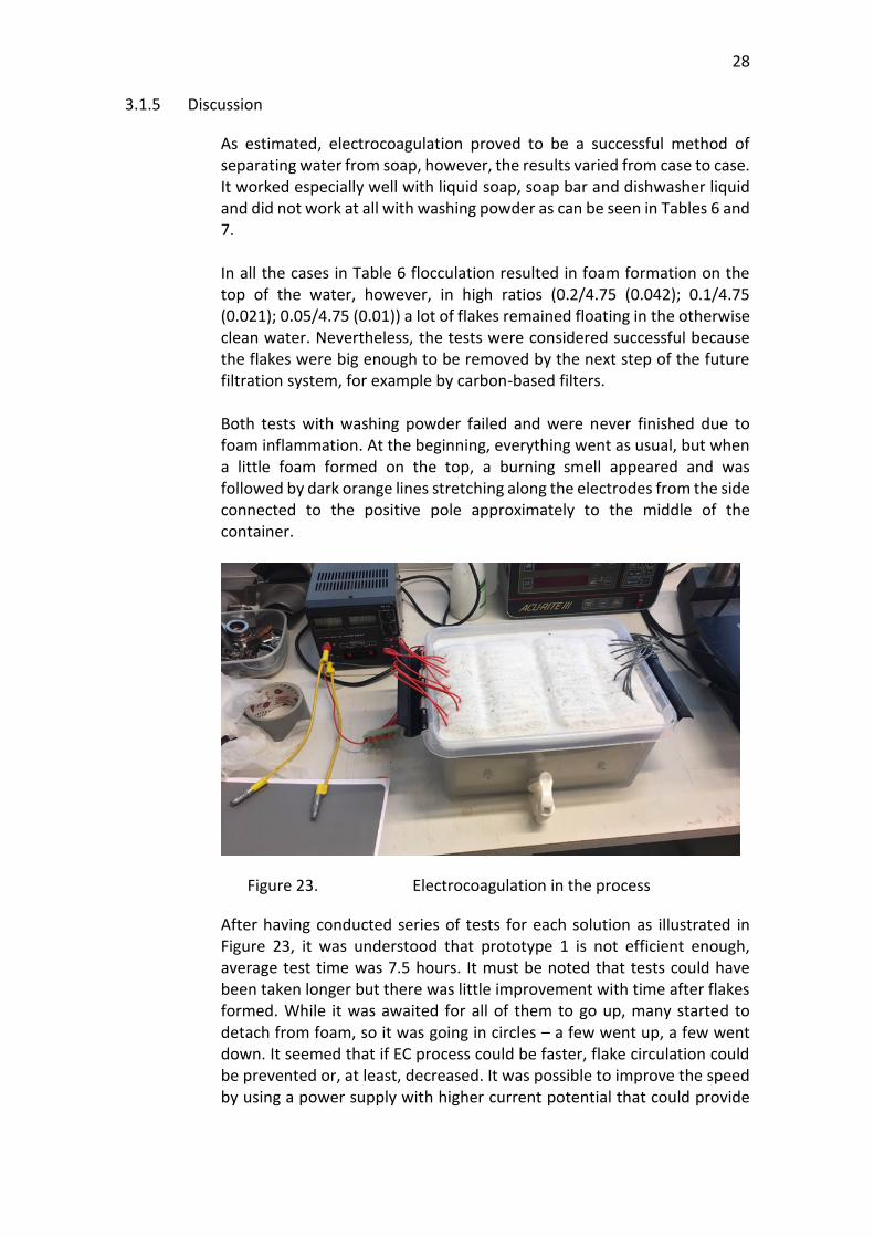
As estimated, electrocoagulation proved to be a successful method of separating water from soap, however, the results varied from case to case. It worked especially well with liquid soap, soap bar and dishwasher liquid and did not work at all with washing powder as can be seen in Tables 6 and 7. In all the cases in Table 6 flocculation resulted in foam formation on the top of the water, however, in high ratios (0.2/4.75 (0.042); 0.1/4.75 (0.021); 0.05/4.75 (0.01)) a lot of flakes remained floating in the otherwise clean water. Nevertheless, the tests were considered successful because the flakes were big enough to be removed by the next step of the future filtration system, for example by carbon-based filters. Both tests with washing powder failed and were never finished due to foam inflammation. At the beginning, everything went as usual, but when a little foam formed on the top, a burning smell appeared and was followed by dark orange lines stretching along the electrodes from the side connected to the positive pole approximately to the middle of the container.
Figure 23. Electrocoagulation in the process
After having conducted series of tests for each solution as illustrated in Figure 23, it was understood that prototype 1 is not efficient enough, average test time was 7.5 hours. It must be noted that tests could have been taken longer but there was little improvement with time after flakes formed. While it was awaited for all of them to go up, many started to detach from foam, so it was going in circles – a few went up, a few went down. It seemed that if EC process could be faster, flake circulation could be prevented or, at least, decreased. It was possible to improve the speed by using a power supply with higher current potential that could provide

29
higher voltage, however, wires used to connect the electrodes were not designed for that. Also, after tests with washing powder, the cathodes were covered by an impermeable and irremovable sediment layer that is presented in Figures 24 and 25. This impaired current transfer through the electrodes and thereby the prototype’s performance. It was realized that washing powder starts other chemical reactions than typical detergents and behaves differently during electrocoagulation. It was decided to omit washing powder in future tests since it was not of primary importance in the first place.
Figure 24. Sediment layer

30
Figure 25. Sediment layer. View from the side
All in all, prototype 1 managed to reach a good level of cleanliness, especially in test solutions mentioned in Table 6, proving electrocoagulation’s concept in removing soap from water. It was still desired to conduct a series of tests with shampoo and hair conditioner as well as repeat the tests with soap and washing liquid with higher voltage, so it was decided to make prototype 2.
3.2 Prototype 2
3.2.1 Aim
Prototype 1 proved the concept of electrocoagulation in terms of separating soap from water, but it was obvious that its efficiency could be improved by increasing the voltage. That would raise the speed of EC operation and therefore the level of water cleanliness which was the aim of prototype 2. It also became clear from prototype 1 that electrocoagulation cannot be used to separate water from washing powder and therefore it was not a part of the experiments of prototype 2.
3.2.2 Set-up
The set-up remained the same as in prototype 1, even though a few details changed. The main difference in prototype 2 was the new power supply of brand Haltronic providing DC up to 30 V and 10 A as shown in Figure 26. It

31
was able to provide a higher current and voltage and therefore copper wires were also changed to higher thickness of 3 mm.
Figure 26. Power supply used in prototype 2
The plastic tank with the tap and the electrodes was new but made of the same material and it was the same size as in prototype 1. The connection of the electrodes remained monopolar and parallel, however, wires from anodes and cathodes were assembled on one side and linked by more convenient terminal connectors as shown in Figure 27. It must be noted that this change did not affect test results in any way.
Figure 27. Terminal connectors in prototype 2

32
A photograph of the new set-up can be seen in Figure 28.
Figure 28. Set-up of prototype 2
Also, with prototype 2 it was decided not to test washing powder due to the unsuccessful results of prototype 1. Instead, shampoo and hair conditioner were added. Table 8 represents updated test solution types based on the water to detergent ratio that were used in the second run of the experiments.

33
Table 8. Test solution types based on water to detergent ratio used in prototype 2
Solution Water Detergent Ratio of detergent/water
A1 Tap water Liquid soap 0.1/4.75 (0.021)
A2 Tap water Liquid soap 0.05/4.75 (0.01)
A3 Tap water Liquid soap 0.025/4.75 (0.005)
A4 Tap water Liquid soap 0.015/4.75 (0.003)
B Tap water Soap bar -
D1 Tap water Dishwasher liquid 0.2/4.75 (0.042)
D2 Tap water Dishwasher liquid 0.1/4.75 (0.021)
D3 Tap water Dishwasher liquid 0.05/4.75 (0.01)
D4 Tap water Dishwasher liquid 0.025/4.75 (0.005)
D5 Tap water Dishwasher liquid 0.015/4.75 (0.003)
E1 Tap water Shampoo 0.1/4.75 (0.021)
E2 Tap water Shampoo 0.05/4.75 (0.01)
E3 Tap water Shampoo 0.025/4.75 (0.005)
E4 Tap water Shampoo 0.015/4.75 (0.003)
F1 Tap water Conditioner 0.05/4.75 (0.01)
F2 Tap water Conditioner 0.025/4.75 (0.005)
F3 Tap water Conditioner 0.015/4.75 (0.003)
3.2.2.1 Experiment results
In the Tables 9 and 10 experiment results of prototype 2 are summarized. In all the tests the current was set to the maximum that the power supply could provide (10 A), but since the conductivity of water changed during experiment, the current and voltage also changed. Therefore, the current was manually held at 9-10 A throughout each test. Also, it must be noted that in the tests with the soap bar different amounts of soap were used because it was practically impossible to estimate the exact quantities.

34
Table 9. Best results of EC tests with prototype 2
Solution Lowest voltage
Maximum voltage
Average voltage
Time Cleanliness
A1 4.24 V 12.1 V 8.32 V 2 h 35 min 7
A2 5.81 V 16.22 V 11.02 V 2 h 40 min 7
A3 9.27 V 20.01 V 14.74 V 1 h 30 min 8
A3 9.2 V 19.9 V 14.55 V 1 h 30 min 8
A4 13.36 V 31.57 V 22.46 V 45 min 9
A4 14.1 V 31.56 V 22.83 V 40 min 9
B 12.08 V 31.58 V 21.83 V 35 min 9
B 13.02 V 31.58 V 22.3 V 40 min 9
D1 4.88 V 13.7 V 9.29 V 3 h 9
D2 5.14 V 18.67 V 11.9 V 3 h 8
D3 7.5 V 25.41 V 16.45 V 2 h 9
D3 8.39 V 25.29 V 16.84 V 2 h 10 min 9
D4 11.55 V 28.43 V 19.99 V 1 h 30 min 9
D4 12.5 V 30.01 V 21.26 V 1 h 45 min 9
D5 15.71 V 31.45 V 23.58 V 40 min 9
D5 12.15 V 31.58 V 21.86 V 40 min 9
D5 14.8 V 31.58 V 23.19 V 35 min 9
Table 10. Second-best results of EC tests with prototype 2
Solution Lowest voltage
Maximum voltage
Average voltage
Time Cleanliness
E1 4.57 V 8.6 V 6.58 V 5 h 6
E2 4.43 V 10.1 V 7.2 V 2 h 40 min 7
E3 13.29 V 31.56 V 22.42 V 2 h 20 min 9
E4 12.1 V 31.58 V 21.84 V 1 h 30 min 9 (10)
F1 4.21 V 7.99 V 6.1 V 4 h 40 min 5
F2 6.4 V 12.38 V 9.39 V 3 h 8
F3 13.36 V 31.57 V 22.46 V 45 min 9(10)
3.2.3 Microscope inspection
Although, the test results looked very promising, it was decided to proof-check the cleanliness test which included smelling, touching and visually inspecting solution after electrocoagulation. The proof-check consisted of making solution ”D5” by mixing tap water with dishwasher liquid in proportions 4.75 L to 15 ml accordingly and taking pictures under microscope before and after electrocoagulation as well as after 20-micron carbon filter. In the Figure 29 soap flakes can be seen as grey flakes and dots where 1 cm equals 50 µm. In Figure 30 the

35
scale is different, 1 cm equals 200 µm and soap particles can be seen merged in big groups. Figure 31 represents the same scale as Figure 29 and shows the final result after carbon filtration.
Figure 29. Soapy water before EC

36
Figure 30. Mixture of water and soap after EC
Figure 31. Mixture of water and soap after EC and carbon filtration
The goal of electrocoagulation in this project was to make it possible for soap to be processed by other means of filtration later since the desired water-purification system in motorhomes will consist of several stages.
3.2.4 Discussion
In prototype 2, a significant improvement was observed in terms of reaction time, on average 1.5 hours was spent for an individual test which corresponded to a reduction in the operation time by more than four times. As for different test solutions, liquid soap, soap bar and dishwasher liquid reacted to electrocoagulation in the same way as in prototype 1, forming a foam layer on top of water. This time the reaction was much faster, and it was noticed that the number of floating flakes by the end of EC process was drastically reduced. In addition, the soapy smell of the water sample became less noticeable. With 100 and 50 ml of shampoo not only was foam formed on top of water but there was sediment at the bottom of the container as well. This is most likely because of the weight of the foam. Shampoo foam was the thickest

37
and heaviest out of all substances tested. Hair conditioner also performed well. It was noticed that electrocoagulation produced the best results with low ratios of detergents (0.025/4.75 (0.005); 0.015/4.75 (0.003)) due to a high conductivity of water. It was possible to reach a voltage of maximum 31.58V and the tests were finished on average after 1 hour. Since these amounts were the closest to the most likely ratio in a motorhome’s greywater tank, the overall outcome was more than satisfactory. The electrodes were also manually cleaned after every ten tests in order to remove the oxidation layer and to keep their high efficiency for as long as possible.

38
4. CONCLUSIONS AND RECOMMENDATIONS FOR FUTURE RESEARCH
This thesis project was aimed to make improvements to a water purification system with the main objective of separating water from soap. The subject was studied thoroughly, and three possible solutions were found: electrocoagulation, distillation and reverse osmosis. Electrocoagulation was chosen for prototyping due to its strong scientific background, successful field applications, low cost and efficiency. EC is the process of water purification treatment by applying an electric current through metal electrodes that are in contact with wastewater. The electric field leads to a release of the electrode’s ions that are later hydrolyzed to form coagulants. The coagulant is the basic ingredient of EC needed to successfully remove the soap particles from the water and guarantee success of flocculation. Building and testing the prototype was required to prove the concept. Prototype 1 proved indeed the effectiveness of electrocoagulation at removing soap but produced results very slowly, on average 7.5 hours per test. This was due to the low voltage and it was assumed that a higher voltage would speed up the process. It was also observed that after the flocculation stage, not all the flakes rose on top to form the foam, instead some rose and some sank, i.e. flake circulation was present. In addition, the water samples still had a distinct soap smell after EC, however, it was thought that the smell was coming from the soap flakes left in water. With prototype 2 a higher current and voltage were applied and that made a significant difference in terms of time. The average test time was decreased to 1.5 hours. The number of floating flakes by the end of the EC process was reduced drastically and therefore the soapy smell of water sample became less noticeable. In some of the test results it was almost insensible. Since this was a prototype tested, further research is needed in order to address the following questions:
− How to automate the removal of foam and sediment after the EC process is finished?
− How to avoid or reduce oxidation of electrodes? Also, before the final water recycling unit can be productized, it is needed to choose the optimal sizes and configuration of the EC unit to fit into the system.

39
REFERENCES
Advance Water Solutions. (2017). Distillation process. Retrieved 17 January 2019 from https://www.advancedwaterinc.com/water-distillation-work/ Akanksha, Roopashree, G.B. & Lokesh, K.S. (2014). Comparative Study of Electrode Material (Iron, Aluminium and Stainless Steel) for Treatment of Textile Industry Wastewater. International Journal of Environmental Sciences 4, pp. 519-531. Retrieved 24 August from https://pdfs.semanticscholar.org/e981/3d926ae3a6da836d011dc1c6bda545858578.pdf Angel Water. (n.d.). Reverse osmosis diagram. Retrieved 1 November 2018 from https://angelwater.com/blog/is-reverse-osmosis-the-best-water/reverse-osmosis-diagram/ Belkacem, M., Bekhti, S. & Bensadok, K. (2007). Groundwater treatment by reverse osmosis. Desalination 206/2007, pp. 100-106. Retrieved 17 January 2019 from https://www.researchgate.net/publication/228489694_Groundwater_treatment_by_reverse_osmosis Cirak, M. (2018). Improvement of RSM-Prediction and Optimization by Using Box-Cox Transformation: Separation of Colloidal Contaminants from Mineral Processing Effluents via Electrocoagulation. Handbook of Research on Predictive Modeling and Optimization Methods in Science and Engineering, pp. 156-191.
Favpng. (n.d.). Self Driving Tour of RV - Car Recreational Vehicle Family Campervan. Retrieved 24 August 2020 from https://favpng.com/png_view/self-driving-tour-of-rv-car-recreational-vehicle-family-campervan-png/gSJ7ScfP Fayad, N. (2017). The application of electrocoagulation process for wastewater treatment and for the separation and purification of biological media. Simple EC cell, p. 6. Retrieved 24 August 2020 from https://tel.archives-ouvertes.fr/tel-01719756/document
Garcia-Seguraa, S., Eibanda M. M. S. G., Vieira de Meloa, J. & Martínez-Huitlea, C. A. (2017). Electrocoagulation and advanced electrocoagulation processes: A general review about the fundamentals, emerging

40
applications and its association with other technologies. Electrodes arrangements in electrocoagulation cells, p.273. Retrieved on 5 March 2019 from https://www.sciencedirect.com/science/article/pii/S1572665717305337 Hillewaert, H. (2011). Osmose. Retrieved 1 November 2018 from https://commons.wikimedia.org/wiki/File:Osmose_en.svg History of Water Filters. (n.d.). Distillation – How does it work? Retrieved 27 August 2020 from http://www.historyofwaterfilters.com/distillation-process.html History of Water Filters. (n.d.). Distillation – Pros and cons. Retrieved 27 August 2020 from http://www.historyofwaterfilters.com/distillation-pc.html Kalogirou, S. (2005). Seawater desalination using renewable energy sources. Progress in Energy and Combustion Science 31(3), pp. 242-281. https://doi.org/10.1016/j.pecs.2005.03.001 Kuokkanen, V., Kuokkanen, T., Rämö, J. & Lassi, U. (2013). Recent Applications of Electrocoagulation in Treatment of Water and Wastewater — A Review. Green and Sustainable Chemistry 3, pp. 89-121. Retrieved 3 March from https://www.researchgate.net/publication/258338067_Recent_Applications_of_Electrocoagulation_in_Treatment_of_Water_and_Wastewater-A_Review Maxfield, M. (2018). Practical Uses of Distillation. Retrieved 10 January 2019 from https://sciencing.com/practical-uses-distillation-6111781.html Mesogeos. (n.d.). Reverse Osmosis for Production of Drinking Water. Retrieved 1 February 2019 from https://mesogeos.gr/en/reverse-osmosis/ Mind Tools. (n.d.). TRIZ. Retrieved 15 March 2019 from https://www.mindtools.com/pages/article/newCT_92.htm Motorhome and RV hire. (n.d.). Day layout. Retrieved 20 August 2019 from https://www.motorhomeandrvhire.com/images/camper-iceland/MH4/plan_day.jpg Motorhome and RV hire. (n.d.). Night layout. Retrieved 20 August 2019 from https://www.motorhomeandrvhire.com/images/camper-iceland/MH4/plan_night.jpg

41
Perez-Gonzalez, A., Urtiaga, A., Ibanez, R. & Ortiz, I. (2012). State of the art and review on the treatment technologies of water reverse osmosis concentrates. Water Research 46 (2), pp. 267-283. Retrieved 26 February 2019 from https://www.sciencedirect.com/science/article/abs/pii/S0043135411006440 PSI Filters. (n.d.). Reverse osmosis waste. Retrieved 1 November 2018 from https://www.psifilters.com.au/content/64-reverse-osmosis-waste Taghizadeh, M. M. (2015). Schematic Design of Electrocoagulation Reactor. Retrieved 8 June 2019 from https://www.researchgate.net/figure/Schematic-Design-of-Electrocoagulation-Reactor_fig1_280043694 The Savvy Campers (n.d.). How Long will a Fresh Water Tank last on a Travel Trailer. Retrieved 24 August 2020 from https://www.thesavvycampers.com/fresh-water/ University of Waikato. (2012). Surfactants. Retrieved 15 March 2019 from https://www.sciencelearn.org.nz/images/1291-surfactants Vasudevan, S., Lakshmi, J. & Sozhan, G. (2011). Effects of alternating and direct current in electrocoagulation process on the removal of cadmium from water. Journal of Hazardous Materials 192 (1), pp. 26-34. Retrieved 15 June 2020 from https://www.sciencedirect.com/science/article/abs/pii/S030438941100519X?via%3Dihub Vepsäläinen, M. (2012). Electrocoagulation in the treatment of industrial waters and wastewaters. Dissertation. Espoo: VTT. Retrieved on 8 June 2019 from https://www.vtt.fi/inf/pdf/science/2012/S19.pdf Water Tectonics. (n.d.). Electrocoagulation Process. Retrieved 22 September 2019 from http://www.watertectonics.com/electrocoagulation/ Webster, W. (1889). Process of purifying sewage by electricity, US398101A. Retrieved 3 March 2019 from https://patents.google.com/patent/US398101A/en Woo, Y., Kim, S.-H., Shon, H. & Tijing, L. (2019). Introduction: Membrane Desalination Today, Past, and Future. Membrane Desalination Systems: the Next Generation, pp. xxv-xlvi. Retrieved 24 August 2020 from https://www.sciencedirect.com/topics/engineering/semipermeable-membrane

42
Yoganand. (2020). How many gallons of water does a rv hold on an average? Updated on May 15 2020. Retrieved 2 August 2020 from https://campergrid.com/rv-water-holding-capacity/