improvements contract number kc000329 section 00 90 00
TRANSCRIPT

1 of 3 Addendum No. 3 Rev. 10/26/2020
North Mercer Island Interceptor and Enatai Interceptor Upgrade-Pump Station Improvements
Contract Number KC000329 Section 00 90 00
Addendum Number 3 Prospective bidders are hereby notified that the bidding documents have been amended as hereinafter set forth:
Ref. Section and
Page or Drawing
Location and Description of Change
VOLUME 4 OF 10 3.1 §07 41 13
page 2 of 6 SHEET METAL ROOFING ¶1.04 DELETE ¶D and REPLACE with: “D. Samples: Submit a minimum of 6 samples of the sheet metal roofing panels at least 4” x 4” square, with finish, color, and texture proposed for the work.”
3.2 §07 41 13 page 3 of 6
SHEET METAL ROOFING ¶2.02.A.2 DELETE ¶a and REPLACE with: “a. Minimum 70 percent resin Kynar 500 or Hylar 5000 fluoropolymer system complying with AAMA 2605; Color: Bronze, as selected by Project Representative from manufacturer’s standard or custom colors.”
3.3 §07 62 00 page 2 of 3
SHEET METAL FLASHING AND TRIM ¶2.01 ADD new paragraph D: “D. Color to match Sheet Metal Roofing.”
3.4 §08 22 00 page 2 of 3
FRP REINFORCED DOORS AND FRAMES ¶2.01.A DELETE ¶2 and REPLACE with: “2. Edgewater Door, ES Model.”
3.5 §08 22 00 page 2 of 3
FRP REINFORCED DOORS AND FRAMES ¶2.03.B DELETE ¶10 and REPLACE with: “10. Color to match Sheet Metal Roofing. If the manufacturer does not offer a standard or custom gelcoat color that matches the Sheet Metal Roofing, paint doors in accordance with Section 09 90 00 Coating System D-1, color to match Sheet Metal Roofing.”
3.6 §08 22 00 page 2 of 3
FRP REINFORCED DOORS AND FRAMES ¶2.03.C DELETE ¶5 and REPLACE with: “5. Color to match Sheet Metal Roofing. If the manufacturer does not offer a standard or custom gelcoat color that matches the Sheet Metal Roofing, paint doors in accordance with Section 09 90 00 Coating System D-1, color to match Sheet Metal Roofing.”

2 of 3 Addendum No. 3 Rev. 10/26/2020
Ref. Section and
Page or Drawing
Location and Description of Change
3.7 §08 22 20page 2 of 3
SOUND-RATED FIBERGLASS REINFORCED PLASTIC DOORS AND FRAMES ¶2.01.A DELETE ¶2 and REPLACE with: “2. Edgewater Door, CGA Model.”
3.8 §08 22 50page 2 of 3
SOUND-RATED FIBERGLASS REINFORCED PLASTIC DOORS AND FRAMES ¶2.03.B DELETE ¶10 and REPLACE with: “10. Color to match Sheet Metal Roofing. If the manufacturer does not offer a standard or custom gelcoat color that matches the Sheet Metal Roofing, paint doors in accordance with Section 09 90 00 Coating System D-1, color to match Sheet Metal Roofing.”
3.9 §08 22 50page 2 of 3
SOUND-RATED FIBERGLASS REINFORCED PLASTIC DOORS AND FRAMES ¶2.03.C DELETE ¶6 and REPLACE with: “6. Color to match Sheet Metal Roofing. If the manufacturer does not offer a standard or custom gelcoat color that matches the Sheet Metal Roofing, paint doors in accordance with Section 09 90 00 Coating System D-1, color to match Sheet Metal Roofing.”
3.10 §09 06 90 SCHEDULES FOR PAINTING AND COATING DELETE in its entirety and REPLACE with revised section attached to this addendum.
3.11 §09 90 00 COATING SYSTEMS DELETE in its entirety and REPLACE with revised section attached to this addendum.
3.12 §26 27 26page 3 of 4
WIRING DEVICES ¶2.04 DELETE ¶C and REPLACE with: “C. Corrosive or outdoor areas: impact resistant, marine grade thermoplastic device plates.” VOLUME 5 OF 10
3.13 §32 31 19 page 4 of 9
DECORATIVE METAL FENCES AND GATES ¶2.03 DELETE ¶M and REPLACE with: “M. Finish for Bar Grating Infill and posts: D-1 coating per 09 06 90.”
3.14 §32 31 19 page 4 of 9
DECORATIVE METAL FENCES AND GATES ¶2.03 DELETE ¶N and REPLACE with: “N. Finish for uncoated ancillary items: D-1 coating per 09 06 90.”

3 of 3 Addendum No. 3 Rev. 10/26/2020
Ref. Section and
Page or Drawing
Location and Description of Change
3.15 §32 31 19 page 7 of 9
DECORATIVE METAL FENCES AND GATES DELETE ¶2.09 in its entirety and REPLACE with: “2.09. FINISH
A. Paint with D-1 Coating per 09 06 90.”
VOLUME 8 OF 10
3.16 A002 ARCHITECTURAL SCHEDULES DELETE: A002 REPLACE with: A002, Addendum 3, Dated 10/19/2021
VOLUME 9 OF 10 3.17 M001 MECHANICAL PIPING SYMBOLS
DELETE: M001 REPLACE with: M001, Addendum 3, Dated 10/22/2021
VOLUME 10 OF 10 3.18 C602 LIFT STATION 11 TESC PLAN AND NOTES
DELETE: C602 REPLACE with: C602, Addendum 3, Dated 10/20/2021
Attached To This Addendum: • §09 06 90, Schedules for Painting and Coating, Addendum 3• §09 90 00, Coating Systems, Addendum 3• A002, Addendum 3, Dated 10/19/2021• M001, Addendum 3, Dated 10/22/2021• C602, Addendum 3, Dated 10/20/2021
This Addendum shall be attached to and form a part of the Contract Documents. All bidders are reminded to acknowledge this Addendum in the E-Procurement system before a bid can be accepted.
Bidders are also reminded to review Clarification documents in the E-Procurement system for responses to timely submitted questions.
10/27/2021
_____________________ Megan Saunders Contract Specialist

Addendum 3 09 06 90 - 1 SCHEDULES FOR PAINTING AND COATING North Mercer Island Interceptor and Enatai Interceptor Upgrade – Pump Station Improvements
SECTION 09 06 90
SCHEDULES FOR PAINTING AND COATING
PART 1 GENERAL
1.01 SUMMARY
A. This Section specifies finishes and colors for rooms, equipment and other items which are to be painted, coated, or have other architectural finishes.
1.02 QUALITY ASSURANCE
A. Referenced Standards: Federal Standard 595 Paint Specification.
B. General: Unless otherwise specified, all materials and workmanship shall conform to the applicable requirements of Section 09 90 00.
C. The King County Project Representative reserves the right to reselect any color, from the manufactures full range of available colors, during the submittal process. In case of conflict between requirements of this section and the specified or listed documents, the requirements of this section shall prevail.
PART 2 PRODUCTS [NOT USED]
PART 3 EXECUTION
3.01 GENERAL
A. In the following schedule, the coating system for each specified surface shall comply with those listed in COATSPEC, Section 09 90 00. Coat surfaces indicated on this schedule unless specifically noted otherwise on the Drawings or in the Specifications. Color reference numbers are from the Federal Standard 595 Paint Spec.
B. Special Equipment Colors: Paint equipment and piping as indicated, except as itemized below: Fire Protection Equipment, Pipes and Apparatus: OSHA Red. Physical hazards in normal operating area and energy lockout devices, included but not limited to,
electrical disconnects for equipment and equipment isolation valves in air and liquid lines under pressure: OSHA Yellow.
C. Electrical conduit is not painted if coated with PVC or specifically noted otherwise on the Drawings or in the Specifications.
3.02 FINISH SCHEDULES
Surfaces Service Environment Coating System
Color
Wet Well, Miscellaneous metal- equipment, exposed conduit, piping, utilities, etc.
Metal in immersed, non-potable, non-immersed corrosive environment
A-1 East Division: # 36270
Wet Well, Miscellaneous concrete- wet wells, tanks, piping, etc.
Concrete in immersed, non-potable, non-immersed corrosive environment
A-2 East Division: # 36270
Miscellaneous metal- equipment, exposed conduit, piping, utilities, etc.
Interior non-immersed, moderate corrosive environment, not exposed to sunlight
B-1 East Division: # 35622

Addendum 3 09 06 90 - 2 SCHEDULES FOR PAINTING AND COATING North Mercer Island Interceptor and Enatai Interceptor Upgrade – Pump Station Improvements
Surfaces Service Environment Coating System
Color
Miscellaneous concrete- dry wells, wash down areas
Interior non-immersed, moderate corrosive environment, not exposed to sunlight
L-1a East Division: # 33711
Miscellaneous metal- equipment, exposed conduit, piping, utilities, handrails,
Interior non-immersed, moderate corrosive environment, exposed to sunlight, salt air, abrasion resistance.
C-1 East Division: # 36270
Concrete, secondary containment. Concrete exposed to chemical leakage: battery storage, pipe trenches and equipment pads associated with the chemicals listed.
Chemicals stored in containment or conveyed are: sodium hydroxide (25% concentration), ferric chloride (35-40% concentration), sodium hypochlorite (15% concentration), citric acid (50% concentration) and both liquid and dry polymers (50% concentration)
C-3 East Division: # 33711
Metal exhaust manifold, exhaust piping
Temperature to 600 degrees F, continuously.
H-1 To be selected.
Concrete floors Interior, traffic area, some standing water.
J-3 East Division: # 33711
Concrete, masonry Interior, walls, mild service, no corrosive, chemical, immersion or salt air exposure.
L-1a East Division: # 33711
Exterior Concrete & masonry
Exterior, non-immersion J-6 Clear
Decorative fence gates, sheet metal roofing & siding trims, flashings, exterior doors, louvers, frames, and site accessories
Exterior non-immersed, noncorrosive, exposure to moisture and sunlight, washdown areas
Factory Finish or D-1
To be selected from manufacturer’s standard or custom colors to match sheet metal roofing color
For Special Equipment Colors see 3.01B.
END OF SECTION

Addendum 3 09 90 00 - 1 COATING SYSTEMS North Mercer Island Interceptor and Enatai Interceptor Upgrade - Pump Station Improvements
SECTION 09 90 00
COATING SYSTEMS
PART 1 GENERAL
1.01 SUMMARY
A. This Section specifies coatings and their surface preparation for field and shop-applied coating systems.
B. Furnish all labor, equipment, including safety equipment, superintendence, materials, tools and incidentals necessary to prepare and coat the work as specified in this Section.
1.02 DEFINITIONS
A. Coating systems: Includes surface description, surface preparation, required dry film thickness, and the number and application procedure of the prime and finish coatings. Systems are as specified within this Section on the Coating System Specification Sheets (COATSPEC).
B. Field coating: The application of the coating system after installation of the surface at the work site.
C. Dry film thickness (DFT): The thickness of a fully cured coating or coating system.
D. Wet film thickness (WFT): The thickness of a coating while wet.
E. Volatile organic content (VOC): The portion of the coating that is a compound of carbon, is photo-chemically reactive and evaporates during drying or curing, expressed in grams per liter or pound per gallon as defined in ASTM D3960.
F. Shop coat: One or more coats applied in a shop or plant prior to shipment to the site.
G. Lead containing: Any coating that contains any detectable amount of lead.
H. Stripe coat: A coat of the specified coating, applied prior to the final coat by brush to all edges (cut or fabricated) on steel shapes, crevices, projections, welds, nuts, bolts, pits, flanges, and splice plates.
I. Hard to reach: Areas that may not be accessible with spray equipment but can be reached by brush, mitt or roller.
J. Inaccessible areas: Areas such as back-to-back angles, skip welds, and other areas where a brush, mitt, or roller cannot contact the surface.
K. pH: A measure indicating whether a solution is acidic, neutral, or alkaline.
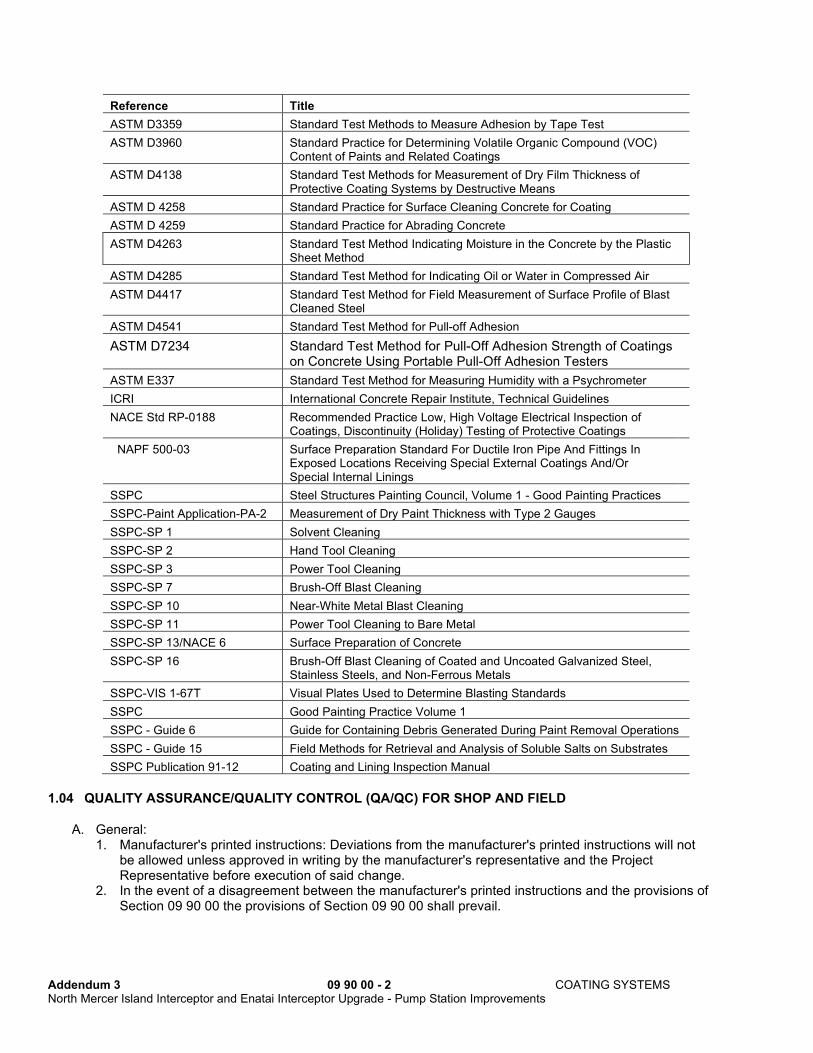
1.03 REFERENCED STANDARDS
A. This Section incorporates by reference the latest revisions of the embedded standard referenced herein. In case of conflict between the requirements of this Section and those of a listed document, the requirements of this Section shall prevail.
Addendum 3 09 90 00 - 2 COATING SYSTEMS North Mercer Island Interceptor and Enatai Interceptor Upgrade - Pump Station Improvements
Reference Title
ASTM D3359 Standard Test Methods to Measure Adhesion by Tape Test
ASTM D3960 Standard Practice for Determining Volatile Organic Compound (VOC) Content of Paints and Related Coatings
ASTM D4138 Standard Test Methods for Measurement of Dry Film Thickness of Protective Coating Systems by Destructive Means
ASTM D 4258 Standard Practice for Surface Cleaning Concrete for Coating
ASTM D 4259 Standard Practice for Abrading Concrete
ASTM D4263 Standard Test Method Indicating Moisture in the Concrete by the Plastic Sheet Method
ASTM D4285 Standard Test Method for Indicating Oil or Water in Compressed Air
ASTM D4417 Standard Test Method for Field Measurement of Surface Profile of Blast Cleaned Steel
ASTM D4541 Standard Test Method for Pull-off Adhesion
ASTM D7234 Standard Test Method for Pull-Off Adhesion Strength of Coatings on Concrete Using Portable Pull-Off Adhesion Testers
ASTM E337 Standard Test Method for Measuring Humidity with a Psychrometer
ICRI International Concrete Repair Institute, Technical Guidelines
NACE Std RP-0188 Recommended Practice Low, High Voltage Electrical Inspection of Coatings, Discontinuity (Holiday) Testing of Protective Coatings
NAPF 500-03 Surface Preparation Standard For Ductile Iron Pipe And Fittings In Exposed Locations Receiving Special External Coatings And/Or Special Internal Linings
SSPC Steel Structures Painting Council, Volume 1 - Good Painting Practices
SSPC-Paint Application-PA-2 Measurement of Dry Paint Thickness with Type 2 Gauges
SSPC-SP 1 Solvent Cleaning
SSPC-SP 2 Hand Tool Cleaning
SSPC-SP 3 Power Tool Cleaning
SSPC-SP 7 Brush-Off Blast Cleaning
SSPC-SP 10 Near-White Metal Blast Cleaning
SSPC-SP 11 Power Tool Cleaning to Bare Metal
SSPC-SP 13/NACE 6 Surface Preparation of Concrete
SSPC-SP 16 Brush-Off Blast Cleaning of Coated and Uncoated Galvanized Steel, Stainless Steels, and Non-Ferrous Metals
SSPC-VIS 1-67T Visual Plates Used to Determine Blasting Standards
SSPC Good Painting Practice Volume 1
SSPC - Guide 6 Guide for Containing Debris Generated During Paint Removal Operations
SSPC - Guide 15 Field Methods for Retrieval and Analysis of Soluble Salts on Substrates
SSPC Publication 91-12 Coating and Lining Inspection Manual
1.04 QUALITY ASSURANCE/QUALITY CONTROL (QA/QC) FOR SHOP AND FIELD
A. General: 1. Manufacturer's printed instructions: Deviations from the manufacturer's printed instructions will not
be allowed unless approved in writing by the manufacturer's representative and the Project Representative before execution of said change.
2. In the event of a disagreement between the manufacturer's printed instructions and the provisions of Section 09 90 00 the provisions of Section 09 90 00 shall prevail.

Addendum 3 09 90 00 - 3 COATING SYSTEMS North Mercer Island Interceptor and Enatai Interceptor Upgrade - Pump Station Improvements
3. Test result disagreement: In the event of a discrepancy between the Contractor and Project Representative's testing equipment, both parties shall check equipment in question for proper function and calibration and retest.
4. Make available all locations and phases of the work for access for inspection by the Project Representative or the manufacturer's representative. Contractor shall provide ventilation, egress, staging and whatever other means are required to access the work area.
5. Contractor QC personnel shall be certified as National Association of Corrosion Engineers, (NACE) CIP, Level 1, for coating work performed at the project site. Contractor QC personnel shall be certified as National Association of Corrosion Engineers, (NACE) CIP, Level 3 with Peer Review, for coating work performed away from the project site.
6. The Project Representative may approve the application of coatings specified under this section by the Contractor’s fabricators and other suppliers without direct inspection by the County provided that the fabricators and suppliers meet the requirements of 1.04A.4 and 1.04B.
B. Contractor's responsibilities: Quality control: responsible for the quality control of the coatings applied and performing check
points as specified in this Section. Schedule: prepare a schedule that is updated weekly or as necessary to show QC and QA Check
Points as specified herein, and distribute to all parties related to installation of the coating system. The schedule shall allow time for remedial work to be completed as identified by inspection at the given checkpoints. The Project Representative shall be informed within 24 hours prior to the Contractor performing the tests specified.
Reports: prepare daily inspection reports when any work is performed on site. Project Representative may require ambient conditions to be recorded as often as needed to insure specified application conditions are met, but not less than twice daily. Tests shall be conducted in accordance with ASTM E337 or in accordance with manufacturer’s instructions for surface temperature and dew point instruments. Use the “Daily Inspection Report” form found in Section 01 33 10. Submit copies of this report within 24 hours of coating application to the Project Representative for signature to acknowledge the report was produced in a timely manner. Submit all reports in bound form at the completion of coating work.
Over coating: verify coating compatibility and primer quality to be equal to the specified primer when over-coating a primer or coating that was applied by others. Follow the coating manufacturer’s recommendations for over coating primers beyond the recoat window.
Provide testing equipment required in this Section and as required to verify compliance with the Specifications. Record of equipment calibration must also be provided.
C. Project Representative's responsibility: QA: determine acceptance or rejection of a coating based on the given specifications. Testing: may conduct tests on ambient conditions, surface temperature, coating(s) applied, target
mil thickness, coating type (i.e. stripe coat), and coating batch numbers in accordance with SSPC Publication 91-12.
D. Checkpoints: Contractor is responsible to perform the checkpoints specified below and as required in COATSPEC. The Project Representative may perform any or all of the checkpoints listed in addition to, but not replacement of, the requirement for the Contractor to perform the inspection checkpoints as specified below.
Blotter test: Upon start-up of abrasive blasting, compressed air shall be checked daily for oil and water by blotter test per ASTM D4285.
Anchor profile: Anchor profile of an abrasively blasted surface shall be tested using Testex tape per ASTM D4417 or with a calibrated digital surface profile gauge. Test shall be conducted on the start-up of the blasting operation to insure proper selection of blast media and prior to prime coat application.
Intermediate DFT readings: DFT readings shall be taken between coats to check consistency of the application and progress toward total system thickness.
Final DFT readings: DFT readings shall be taken per SSPC PA-2 on total system thickness as criteria for final acceptance of a coating. If recoat time has been exceeded or if recommended by the manufacturer, deficient areas shall be scarified prior to top coating. Dry film thickness

Addendum 3 09 90 00 - 4 COATING SYSTEMS North Mercer Island Interceptor and Enatai Interceptor Upgrade - Pump Station Improvements
measurements in excess of the amounts specified in SSPC PA-2 may be acceptable if approved by the Project Representative.
Holiday testing: Perform for the entire coating per NACE RP-0188 in the presence of the Project Representative. Any holidays detected shall be repaired and retested after cure of the coating is complete.
Surface preparation: Shall be accepted by the Project Representative prior to the application of a coating.
Ambient conditions: Perform tests for relative humidity, surface temperature, dew point and ambient temperature to ensure compliance for materials applied. Tests shall be conducted in accordance with ASTM E337 or surface temperature instrument and dew point instrument manufacturer's instructions.
Adhesion: perform adhesion tests per ASTM D4541, ASTM D3359 Test Method B, or ASTM D7234 depending upon the substrate. It is the responsibility of the Contractor to repair any damage to the coating resulting from adhesion testing. a. Minimum adhesion values for coating systems A-1, A-2, and A-3: 400 psi with 20 mm dolly or 64
psi with 50 mm dolly b. The minimum adhesion score for coating system L-1a using ASTM D3359 Test Method B shall
be Classification 2B. Test to Determine Salt Contamination: Using the Bresle Method, the Contractor shall take 3 tests
each day at randomly selected locations during surface preparation prior to coating application. For immersed surfaces, the reading shall not exceed 30 microsiemens/cm (30 us/cm). For non-immersed surfaces, the reading shall not exceed 70 microsiemens/cm (70 us/cm). If conductivity measurements exceed the respective values, the affected surfaces shall be cleaned until conductivity levels are acceptable. Tests shall be conducted in accordance with SSPC - Guide 15 or soluble salt test kit manufacturer's instructions. This test may be waived by the Project Representative if initial tests indicate low salt concentrations.
Moisture in Concrete: perform ASTM 4263-88, Standard Test Method Indicating Moisture in the Concrete by the Plastic Sheet Method. If the presence of moisture is indicated, dry the substrate prior to coating application. Perform this test once for every 200 square feet of area to be coated and more frequently at darkened concrete areas. Perform Calcium Chloride Moisture Vapor Emissions Tests in accordance with ASTM F-1869 for all floors, containment, below grade applications or any other moisture tests required by the manufacturer. The Project Representative may approve adhesion testing of a small coating test patch per ASTM D7234 in lieu of moisture testing.
11. Test for de-passivation of galvanized steel: After cleaning galvanized steel by pressure wash and soap or other manufacturer-approved method, test every 100 square feet by applying a drop of Copper Sulfate test solution. Black color indicates that the galvanized steel has been de-passivated. Refer to Section 09 90 00 3.01 B.5.
12. Pressure washing QA/QC: a. Wash water temperature verification: Dispense wash water into a 5 gallon bucket. Verify that
wash water is between 120F and 130F with a calibrated infrared thermometer. b. Pump flow rate- Spray wash water into a 5 gallon bucket. Water level shall rise to 3 gallon mark in
60 seconds or less. c. Pump pressure- For a 3,000 PSI rated machine, the pressure at spray gun inlet shall be not less
than 2,900 PSI with the trigger pulled and nozzle discharging water on a calibrated pressure gauge.
d. Nozzle orifice size: Example: A properly sized new #3.5 (.048”) pressure washing nozzle will pass a # 56 (.0465”) drill bit or drill blank but will not pass a # 55 (.052”) drill bit or drill blank. A nozzle shall be replaced when its orifice passes a drill bit or drill blank .004” larger than the original orifice diameter.
E. Disputes: If questions arise concerning the acceptability of an applied coating, Tooke, adhesion, and other destructive/non-destructive tests per ASTM D 4138 may be performed to aid in resolution of the dispute. If the coating is determined to be defective, the Contractor will be responsible for the cost of repairs resulting from testing. If the coating is shown to be properly applied, the County will be responsible for the cost of inspection repairs.

Addendum 3 09 90 00 - 5 COATING SYSTEMS North Mercer Island Interceptor and Enatai Interceptor Upgrade - Pump Station Improvements
1.05 SUBMITTALS
A. Procedures: Section 01 33 00.
B. Contractor QC personnel.
C. A list of materials shall be provided before materials are delivered to the worksite.
D. A Waste Disposal Plan.
E. For each primer and finish coating, provide the manufacturer's application instructions, which shall include the following: 1. Surface preparation recommendations. 2. Primer type, where required. 3. Maximum dry and wet mil thickness per coat. 4. Minimum and maximum curing time between coats, including atmospheric conditions for each. 5. Curing time before submergence in liquid. 6. Thinner to be used with each coating. 7. Ventilation requirements. 8. Allowable application methods. 9. Maximum storage life. 10. Material safety data sheets. 11. Interpretation of batch code numbers. 12. Minimum and maximum relative humidity requirements. 13. Minimum and maximum surface temperature requirements. 14. Minimum and maximum ambient temperature requirements. 15. Manufacturers recommended application procedure. 16. LEED Submittal. 17. When color is not specified, provide manufacturer's range of standard colors. 18. Contractor QC personnel qualifications.
F. Provide information on blasting media including coating manufacture's recommended grit/shot size for coating systems specified.
G. Field and/or draw-down samples may be requested by the Project Representative.
H. For Systems A-2 and C-3, submit manufacturer's details for construction joints, penetrations, crack repair, and details at floor penetrations, wall bases, equipment bolts, embedded angle frames, transitions and terminations of the system and all other details specific to the structure being coated.
I. Ventilation plan for enclosed application of required systems.
1.06 DELIVERY, STORAGE AND HANDLING
A. Deliver materials for field application to the job site in their original, unopened containers. Each container shall bear the manufacturer's name brand, batch number, date of manufacture, and storage life.
B. Coatings shall be stored in enclosed structures and shall be protected from weather and excessive heat or cold. Coatings, exceeding storage life recommended by the manufacturer or that have been visibly damaged shall be removed from the site. Flammable materials shall be stored in accordance with state and local codes.

Addendum 3 09 90 00 - 6 COATING SYSTEMS North Mercer Island Interceptor and Enatai Interceptor Upgrade - Pump Station Improvements
1.07 SITE CONDITIONS
A. Coatings shall be applied only to surfaces that are dry, and only under such combination of humidity and temperatures of the atmosphere and surfaces to be coated as will cause evaporation rather than condensation.
B. During coating and for a period of at least 8 hours after the coating has been applied, the temperature of the surface and the atmosphere shall be maintained at a minimum of 5 degrees above the dew point unless the curing schedule for the coating permits otherwise.
C. Provide environmental controls such as heaters and/or dehumidification if atmospheric requirements as specified in this Section are not met or workdays are lost due to weather.
D. Provide ventilation if the cure time of the coating is slowed by the presence of coating or solvent vapor.
1.08 CONTAINMENT
A. Containment shall conform to SSPC-Guide 6. Level of containment shall be as specified to capture debris, contain dust, protect from adverse weather, control overspray, and provide means to control ambient conditions, and shall be as specified for the material and service conditions in the COATSPEC.
B. Containment is required whenever abrasive blasting is performed. The Contractor is responsible for any damage resulting from surface preparation or painting operations.
SSPC-GUIDE 6 - TABLE A
COMBINATIONS OF CONTAINMENT AND VENTILATION SYSTEMS COMPONENTS
Containment Classification
CONTAINMENT SYSTEM (5.3 of Guide) VENTILATION (5.4 of Guide)
5.3.1
Containment Materials
5.3.2
Penetrability
5.3.3
Support Structure
5.3.4
Joints
5.3.4
Joints
5.3.5
Entryway
5.4.1
Make-up
5.4.2 Input
Air Flow
5.4.3 Air
Pressure
5.4.4 Air
Movement
5.4.5
Exhaust Dust Filtration
Class 1A B1-Air
Impenetrable
C1-Rigid
C2-Flexible
D1-Full
Seal
D1-Full
Seal
E1-Airlock
E2-Resealable
F1-
Controlled
G1-Forced
G2-Natural
H1-
Instrument Verification H2-Visual Verification
I1-Minimum
Specified
J1-Air
Filtration
Class 2A A1-Rigid 2-Flexible
B1-Air Impenetrable
C1-Rigid C2-Flexible
D1-Full Seal
D1-Full Seal
E2-Resealable E3-Overlap
F1-Controlled F2-Open
G1-Forced G2-Natural
H2-Visual Verification
I1-Minimum Specified
J1-Air Filtration
Class 3A A1-Rigid A2-Flexible
B1-Air Impenetrable B2-Air Penetrable
C1-Rigid C2-Flexible
D1-Full Seal D2-Partial Seal
D1-Full Seal D2-Partial Seal
E4-Open Seam
F1-Controlled F2-Open
G1-Forced G2-Natural
H3-Not required
l2-Not specified
J1-Air Filtration
Class 4A A1-Rigid A2-Flexible
B1-Air Impenetrable B2-Air Penetrable
C3-Minimal
D2-Partial Seal
D2-Partial Seal
E4-Open Seam
F2-Open G2-Natural H3-Not required
l2-Not specified
J2-No Controls on Exhaust
Note:
1. The information in this table is provided for guidance only and does not guarantee that any specific levels of containment will be achieved by following the suggestions. The type of structure, wind conditions, soundness of the materials of construction, and many other factors play a role in containing dust and debris.
2. The table occasionally identifies two options for a given component. For example, containment materials (5.3.1) are shown as being either rigid or flexible. If the specifier requires the use of rigid materials only, this restriction must be specified separately.
3. The design suggestions made in this table are based on the use of open abrasive blast cleaning inside containment. The classifications are ordered from the greatest degree of dust and debris containment (Class 1A). Normally, the higher the degree of containment, the higher the cost.
4. Many other combinations of the components beyond those suggested above can be used to provide similar results. The method preparation can also be adjusted to reduce or eliminate dust emissions.
5. Certain combinations of components within which each class may not be suitable when removing hazardous paints (e.g., forced air input in combination with penetrable containment materials in Class 3A).

Addendum 3 09 90 00 - 7 COATING SYSTEMS North Mercer Island Interceptor and Enatai Interceptor Upgrade - Pump Station Improvements
6. When designing a ventilation system, care must be taken to balance the static pressure with the input air flowto avoid collapsing the containment due to high negative pressure.
1.09 WARRANTY
A. For the Work of this Section, provide all warranties as described in the General Conditions 00 72 00, andspecial warranties as specified in the Technical Specifications
PART 2 PRODUCTS
2.01 MATERIALS
A. Standardization:Materials, supplies, and articles provided shall be the standard products of manufacturers. Coatings in a particular system shall be the products of a single manufacturer. The standard products of manufacturers other than those specified may be accepted when it is demonstrated that they are equal in composition, durability, usefulness, and convenience for the purpose intended. Requests for substitutions will be considered when submitted per Section 01 33 00 provided the following minimum conditions are met: a. The proposed coating system shall use an equal or greater number of separate coats to
achieve the required dry film thickness.b. The proposed coating system shall use coatings of the same generic type. The directions for
application and descriptive literature which includes generic type, non-volatile content byvolume, material safety data sheets, VOC's by grams per liter, and other information confirmsthat the substitution is equal to the specified coating system.
B. All coating materials shall be benzene and lead free and shall not, exceed 250 grams per liter of volatileorganic compounds (VOC).
C. Blasting material shall meet MIL-A-22262A (SH) and shall be arsenic-free and contain no free silica.Blasting material shall not be reused. The Contractor is responsible for removing and legally disposingof the spent blasting material from the job site. The Contractor shall provide a copy of totalcharacteristic leaching procedure (TCLP) results of the spent blast material to the ProjectRepresentative prior to Final Acceptance of the work.
D. Nonskid additive shall be 20 to 40 mesh alumina oxide, unless alternate nonskid media isrecommended by the manufacturer.
2.02 EQUIPMENT
A. The Contractor is responsible for ensuring that all King County equipment including mechanical workingparts and/or moving parts within the work area are protected from damage. Protection of equipment willbe coordinated with the Project Representative.
PART 3 EXECUTION
3.01 PREPARATION
A. General:1. The surface preparation instructions Section 09 90 00 3.01 are general only and are not intended to
replace the specific requirements of the individual COATSPECS or coating manufacturer’srequirements.
2. Surfaces to be coated shall be clean. Before applying coating, oil and grease shall be removed perSSPC-SP 1. All dirt, rust, loose mill scale, old weathered coatings, and other foreign substances shallbe cleaned according to the SSPC standards specified in the COATSPEC. Oil and grease shall beremoved before mechanical cleaning is started. Where mechanical cleaning is accomplished by blast

Addendum 3 09 90 00 - 8 COATING SYSTEMS North Mercer Island Interceptor and Enatai Interceptor Upgrade - Pump Station Improvements
cleaning, the abrasive used shall be washed, graded, and free of contaminants, which might interfere with the adhesion of the coatings.
3. Clean cloths and clean fluids shall be used in solvent cleaning. Cleaning and coating shall be scheduled so that dust and spray from the cleaning process will not fall on wet, newly coated surfaces. Ensure that field coating is compatible with factory applied or existing coatings.
B. Metallic surfaces: Metallic surfaces shall be prepared in accordance with applicable portions of the NACE, SSPC, or
ASTM surface preparation specifications. Specific applicable standards are specified in each coating system. The solvent in solvent cleaning operations shall be as recommended by the manufacturer.
Preparation of metallic surfaces shall be based upon comparison with SSPC-VIS-1-67T, or as described herein. To facilitate inspection on the first day of sandblasting operations, sandblast a sample area to the standards specified. Plates of light metal steel shall measure a minimum of 8-1/2 inches x 11 inches. The blasted sample area meeting the requirements of the Specifications shall be initialed by the Contractor and the Project Representative and covered with clear plastic and tape. One of these sample areas shall be prepared for each type of sandblasting and shall be used as the comparison standard throughout the work.
Profile of blasted surfaces of new steel or previously coated steel shall be per the manufacturer's recommendation for each coating system but be no less than two mils. Tightly adhered, existing coating remaining on surface following SSPC-SP-7, cleaning shall have a minimum surface profile of 2 mils.
Surface preparation for aluminum, copper, brass, and stainless steel shall be as specified for the coating in the COATSPEC.
Surface preparation for galvanized metal shall include a pressure wash with a cleaning solution recommended by the coating manufacturer, mixed and rinsed with 130-degree water and applied at 3000 psi, 2.8 GPM minimum. When the surface is dry, prepare for coating application by providing a cleaning per SSPC-SP 2 or 3. Alternative surface preparation methods shall be per the manufacturer’s written direction for profile and surface cleanliness for the given application. Perform de-passivation test listed in Section 09 90 00 1.04 D.11.
Areas not accessible or appropriate for blast cleaning may be hand or power tool cleaned with written approval of the Project Representative.
C. Concrete, masonry and plaster surfaces: Surfaces, which are to be coated shall be allowed to age for at least 28 days or longer, to dry to the
moisture content recommended by the coating manufacturer. Moisture content shall be tested per ASTM D4263. The presence of moisture indicates additional cure time will be required. Retest as required until concrete is sufficiently dry for coating.
Muriatic acid solution shall not be used. Loose concrete and laitance shall be removed by blasting or chipping. Voids and cracks shall be
repaired as specified in Section 03 30 00 or applicable COATSPEC. When repair work in Section 03 30 00 is complete, prepare the surface per the following: a. Concrete floors shall be prepared with “blast track” style equipment or an Approved Equal. b. All concrete surfaces shall be inspected per SSPC-SP 13 to ICRI Technical Guideline #310.2
and per the manufacturer’s recommendations. Surfaces shall be dry and clean and free from grit, loose plaster, and surface irregularities. Cracks and holes shall be repaired with acceptable patching materials, keyed to existing surfaces,
and sanded smooth. Surfaces may require additional repair to provide a smooth surface prior to application of final coat.
The pH of the surface shall register a '7', which indicates a neutral surface condition, before coating is applied. If indicator reads above '7', the alkali shall be neutralized.
Surfaces shall be cleaned with clear water by washing and scrubbing to remove foreign and deleterious substances.
Steam cleaning shall be used to clean wall surfaces of existing process channels, structures and tanks to be coated.
Surfaces to be coated shall be repaired as specified in the COATSPEC, and cleaned and finished to the standards as specified herein.
Addendum 3 09 90 00 - 9 COATING SYSTEMS North Mercer Island Interceptor and Enatai Interceptor Upgrade - Pump Station Improvements
D. Ductile Iron Pipe: 1. As specified in Section 33 05 19. 2. Refer to Section 09 06 90 for exterior topcoat or finish coating systems. 3. Refer to Section 40 05 01 for interior pipe, valve, and fitting lining systems.
E. Plastic surfaces: Clean with solvent compatible with the specified primer and hand sanded with a medium grit
sandpaper to provide sufficient profile for the coating system. Large areas may be power sanded or brush off blasted provided sufficient controls are employed so the surface is roughened without removing excess material.
3.02 APPLICATION
A. Workmanship: Coating shall be conducted in accordance with the requirements of SSPC, Good Painting Practice Volume 1.
Coated surfaces shall be free from runs, drips, ridges, waves, laps and brush marks. Coats shall be applied so as to produce an even film of uniform thickness.
Coating equipment shall be designed for application of the materials specified. a. Compressors shall have traps and filters to remove water and oils. b. Spray equipment shall be equipped with mechanical agitators, pressure gages, and pressure
regulators, and spray nozzles of the proper sizes and functioning in a manner suitable to perform the work.
Each coat of paint shall be applied evenly and sharply cut to line.
B. Coating properties, mixing, and thinning: Coating shall provide a satisfactory film with smooth even surface. Glossy undercoats shall be
lightly sanded to provide a surface suitable for the proper application and adhesion of subsequent coats. Orange Peel, overspray, pinholes and other surface defects shall be repaired.
Coating shall be thoroughly stirred, strained, and kept at a uniform consistency during application. Coatings shall be mixed in accordance with the manufacturer's instructions.
C. Method of coating application: Prime coatings may be shop or field applied. Shop-applied primer shall be as specified in each
system. Provide mechanical equipment, including, but not limited to, pumps, valves, pipe, blowers, fittings,
and miscellaneous appurtenances, with shop-applied primer and shop-applied finish coats. If the shop coating meets the requirements of this Section, the field coating may consist of touching
up the shop prime coat to achieve the film thickness, continuity, and coating specified in the COATSPEC. Damaged and poorly applied shop coatings that do not meet the specified requirements shall be removed, surface prepared, and then recoated in accordance with the COATSPEC.
Where two or more coats are required, alternate coats shall contain sufficient compatible color additive, to act as indicator of coverage or the alternate coats shall be of contrasting colors.
Mechanical equipment on which the manufacturer's shop-applied coating is acceptable shall be touch-up primed and coated with the specified coating system to match the color scheduled.
Coating shall not be applied to a surface until it has been prepared as specified. A stripe coat shall be applied by brush to all edges (cut or fabricated), crevices, projections, nuts,
bolts, pits, welds, flanges and splice plates. Subsequent coats may be either brush or spray applied.
Where nonskid surface is scheduled, broadcast nonskid additive at 5 pounds per 30 square feet. Back-roll on horizontal surfaces.
D. Film thickness and continuity: Coating system thickness is the total thickness of primer and finish coats and does not include
sealers, patching mortars or galvanized coatings. Coatings shall be applied to the thickness specified. No less than two coats shall be applied.
Addendum 3 09 90 00 - 10 COATING SYSTEMS North Mercer Island Interceptor and Enatai Interceptor Upgrade - Pump Station Improvements
E. Unsatisfactory Application: If an item has an improper finish color or insufficient film thickness, clean surface and topcoat with
specified paint material to obtain specified color and coverage. Obtain specific surface preparation information from coating manufacturer.
Evidence of runs, bridges, shiners, laps, or other imperfections is cause for rejection. Repair defects in accordance with written recommendations of coating manufacturer.
F. Damaged Coatings, Pinholes, and Holidays: Feather edges and repair in accordance with recommendations of paint manufacturer. Hand or power sand visible areas of chipped, peeled, or abraded paint, and feather the edges.
Follow with primer and finish coat. Depending on extent of repair and appearance, a finish sanding and topcoat may be required.
Apply finish coats, including touchup and damage-repair coats in a manner that will present a uniform texture and color-matched appearance.
3.03 CLEANUP AND WASTE DISPOSAL
A. At the end of each shift, remove surplus materials, protective coverings, and accumulated rubbish.
B. Thoroughly clean all surfaces and repair any overspray or other paint-related damage when the work is complete.
C. All solvents, unused coatings and cleaning solutions shall be removed from the site and disposed of legally when coating work is complete or if directed by the Project Representative.
D. Prepare a Waste Disposal Plan to demonstrate all waste material is to be properly disposed; Include: Specify the Contractor is the generator of all waste materials generated by their business activities. Provide details on procedures to be used for properly managing and disposing of waste materials in
accordance all applicable laws and regulations. Procedures to document waste types and quantities generated and their disposition. Appoint an employee who is qualified and authorized to enforce proper waste disposal and
document the disposal.
E. Submit completed Waste Disposal Plan and supporting documentation to demonstrate quantities and proper disposal of wastes.
3.04 PROTECTION
A. Where protection is provided for coated surfaces, such protection shall be preserved in place until the coating film has properly dried, and removal of the protection is authorized by the Project Representative. Items, which have been coated shall not be handled, worked on, or otherwise disturbed, until the coating is completely dry and hard.
B. Hardware, electrical fixtures, nameplates, shims and similar accessories shall be removed or masked during preparation and coating operations or shall otherwise be satisfactorily protected. Equipment adjacent to walls shall be disconnected and moved to permit cleaning and coating of equipment and walls and, following coating, shall be replaced and reconnected. Any removal or disconnecting of equipment shall be coordinated with the Project Representative.
3.05 MANUFACTURER'S SERVICES
A. Coating manufacturer's representative shall be present at site as follows: Within 48 hours of first application of any coating system. As required to resolve field problems attributable to or associated with manufacturer's product. To verify full cure of coating prior to coated surfaces being placed into immersion service.
Addendum 3 09 90 00 - 11 COATING SYSTEMS North Mercer Island Interceptor and Enatai Interceptor Upgrade - Pump Station Improvements
3.06 COATING SYSTEMS
A. Surfaces to be coated, surfaces not to be coated, coating systems to be used, and required finishes and colors are specified in Section 09 06 90.
3.07 COATING SYSTEM SPECIFICATION SHEET - COATSPEC
A. Coating Systems specified for use appear on the following pages. Each of the Coating Systems and their requirements appear on individual pages.
Addendum 3 09 90 00 - 12 COATING SYSTEMS North Mercer Island Interceptor and Enatai Interceptor Upgrade - Pump Station Improvements
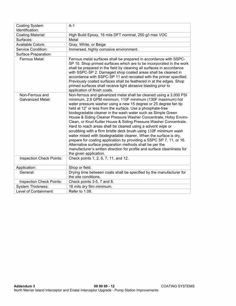
Coating System Identification:
A-1
Coating Material: High Build Epoxy, 16 mils DFT nominal, 250 g/l max VOC
Surfaces: Metal
Available Colors: Gray, White, or Beige
Service Condition: Immersed, highly corrosive environment.
Surface Preparation:
Ferrous Metal: Ferrous metal surfaces shall be prepared in accordance with SSPC-SP 10. Shop primed surfaces which are to be incorporated in the work shall be prepared in the field by cleaning all surfaces in accordance with SSPC-SP 2. Damaged shop coated areas shall be cleaned in accordance with SSPC-SP 11 and recoated with the primer specified. Previously coated surfaces shall be feathered in at the edges. Shop primed surfaces shall receive light abrasive blasting prior to application of finish coats.
Non-Ferrous and Galvanized Metal:
Non-ferrous and galvanized metal shall be cleaned using a 3,000 PSI minimum, 2.8 GPM minimum, 110F minimum (130F maximum) hot water pressure washer using a new 15 degree or 25 degree fan tip held at 12” or less from the surface. Use a phosphate-free biodegradable cleaner in the wash water such as Simple Green House & Siding Cleaner Pressure Washer Concentrate, Hotsy Enviro-Clean, or Krud Kutter House & Siding Pressure Washer Concentrate.
Hard to reach areas shall be cleaned using a solvent wipe or
scrubbing with a firm bristle deck brush using 110F minimum wash water mixed with biodegradable cleaner. When the surface is dry, prepare for coating application by providing a SSPC SP 7, 11, or 16. Alternative surface preparation methods shall be per the manufacturer’s written direction for profile and surface cleanliness for the given application.
Inspection Check Points: Check points 1, 2, 6, 7, 11, and 12.
Application: Shop or field.
General: Drying time between coats shall be specified by the manufacturer for the site conditions.
Inspection Check Points: Check points 3-5, 7 and 8.
System Thickness: 16 mils dry film minimum.
Level of Containment: Refer to 1.08.

Addendum 3 09 90 00 - 13 COATING SYSTEMS North Mercer Island Interceptor and Enatai Interceptor Upgrade - Pump Station Improvements
Coatings:
ALTERNATIVE 1
Primer: One coat of Carboline Carboguard 635 VOC Epoxy
Stripecoat: One coat of Carboline Carboguard 635 VOC Epoxy
Intermediate: One coat of Carboline Carboguard 635 VOC Epoxy
Finish: One or more coats of Carboline Carboguard 635 VOC Epoxy
ALTERNATIVE 2
Primer: One coat of Devoe Bar Rust 236 Multi-Purpose Epoxy
Stripecoat: One coat of Devoe Bar Rust 236 Multi-Purpose Epoxy
Intermediate: One coat of Devoe Bar Rust 236 Multi-Purpose Epoxy
Finish: One or more coats of Devoe Bar Rust 236 Multi-Purpose Epoxy
ALTERNATIVE 3
Primer: One coat of ENECON Chemclad SC
Stripecoat: One coat of ENECON Chemclad SC
Intermediate: One coat of ENECON Chemclad SC
Finish: One or more coats of ENECON Chemclad SC
ALTERNATIVE 4
Primer: One coat of Sherwin Williams Macropoxy 646 B58-600
Stripecoat: One coat of Sherwin Williams Macropoxy 646 B58-600
Intermediate: One coat of Sherwin William Macropoxy 646 B58-600
Finish: One or more coats of Sherwin Williams Macropoxy 646 B58-600
ALTERNATIVE 5
Primer: One coat of Tnemec Series V69 Epoxoline.
Stripecoat: One coat of Tnemec Series V69 Epoxoline
Intermediate: One coat of Tnemec Series V69 Epoxoline
Finish: One or more coats of Tnemec's Series V69 Epoxoline

Addendum 3 09 90 00 - 14 COATING SYSTEMS North Mercer Island Interceptor and Enatai Interceptor Upgrade - Pump Station Improvements
Coating System Identification:
A-2
Coating Material: High Build Epoxy, 16 mils DFT nominal, 250 g/l max VOC
Surfaces: Concrete, masonry (walls above Wet Well wall liner)
Available Colors: Gray, White, or Beige
Service Condition: Immersed, highly corrosive environment.
Surface Preparation: For concrete, masonry and plaster.
Surfaces shall be allowed to age for at least 28 days and allowed to dry to the moisture content recommended by the coating manufacturer. Moisture content will be tested by the Contractor and witnessed by the Project Representative. Loose concrete, form oils, surface hardeners, curing compounds, and laitance shall be removed from surfaces and voids and cracks shall be repaired per Section 03 30 00. When repair work in Section 03 30 00 is complete, prepare concrete per SSPC-SP 13 to ICRI Technical Guideline #03732 CSP 3 minimum profile. Holes or other joint defects shall be filled with mortar and re-pointed. Loose or splattered mortar shall be removed by scraping and chipping.
Surfaces shall be cleaned with a minimum 5,000 PSI pressure wash using a new turbo nozzle in accordance with SSPC-SP 13. Muriatic acid shall not be used. After cleaning, apply skim coat of specified patching mortar to 100% of the surface to repair bugholes, other imperfections and provide a monolithic surface.
Inspection Check Points: Check points 2, 6, 7, and 10-12.
Application: 1. Field. 2. Patching mortar shall dry a minimum of 48 hours prior to primer
application. 3. Prime coat shall be applied as recommended by the coating
manufacturer, provided the coating as applied, complies with prevailing air pollution control regulations.
4. Drying time between coats shall be as recommended by coating manufacturer.
Inspection Check points: Check points 3-5, 7 and 8.
System Thickness: 16 mils dry film, excluding patching mortar.
Level of Containment: Refer to 1.08.

Addendum 3 09 90 00 - 15 COATING SYSTEMS North Mercer Island Interceptor and Enatai Interceptor Upgrade - Pump Station Improvements
Coatings:
ALTERNATIVE 1
Patching Mortar: One or more coats of Carboline Carboguard 501 Epoxy Filler.
Primer: One coat of Carboline Carboguard 635 VOC Epoxy, applied at 10 mils wet film.
Finish: One Three or more coats of Carboline Carboguard 635 VOC Epoxy, applied at 5 mils wet film each coat.
ALTERNATIVE 2
Patching Mortar: One or more coats of Devoe Devfil 145 Epoxy Filler. Note that epoxy filler shall be applied after application of primer.
Primer: One coat of Devoe's Pre-Prime 167, applied at 3 mils wet film.
Finish: Three or more coats of Devoe Bar Rust 236 Multi-Purpose Epoxy, applied at 5 mils wet film each coat.
ALTERNATIVE 3
Patching Mortar: One or more coats of ENECON Enecrete DuraQuartz.
Primer: One coat of ENECON Chemclad SC, applied at 10 mils wet film.
Finish: Two or more coats of ENECON Chemclad SC, applied at 10 mils wet film each coat.
ALTERNATIVE 4
Patching Mortar: One or more coats of Sherwin-Williams Dura-Plate 2300.
Primer: One coat of Sherwin Williams Macropoxy 646 B58-600, applied at 10 mils wet film.
Finish: Two or more coats of Sherwin Williams Macropoxy 646 B58-600, applied at 10 mils wet film each coat.

Addendum 3 09 90 00 - 16 COATING SYSTEMS North Mercer Island Interceptor and Enatai Interceptor Upgrade - Pump Station Improvements
Coating System Identification:
A-3
Coating Material: Surface Filler and 100% Solids Sprayable Lining System, 125 mils DFT nominal
Surfaces: Concrete, Masonry, and Miscellaneous Metals.
Service Condition: Immersed, moderately corrosive environment.
Surface Preparation:
Follow Manufacturer’s recommendation for crack repair and details at penetrations, construction joints, equipment bolts, anchors, transitions and terminations at edge of system, and other details specific to the structure being coated. The Contractor may use a trowel-applied formulation of the approved lining system if available from the manufacturer.
New: Surfaces shall be allowed to age for at least 28 days and allowed to dry to the moisture content recommended by the coating manufacturer. Concrete and masonry surfaces shall be cleaned with a minimum 5,000 PSI at 3 gpm pressure wash using a new turbo nozzle in accordance with SSPC-SP 13 to ICRI Technical Guideline #03732 CSP 3 minimum profile. Metals shall be prepared to SSPC-SP10 Near White Blast Cleaning.
Existing: Concrete and masonry surfaces shall be cleaned with a minimum 5,000 PSI at 3 gpm pressure wash using a new turbo nozzle in accordance with SSPC-SP 13 to ICRI Technical Guideline #03732 CSP 5 minimum profile. Metals shall be prepared to SSPC-SP 10 Near White Blast Cleaning.
Inspection Check points: Check points 2, 6, 7, and 10.
Application: 1. Allow patching mortar/surface filler shall to cure according to manufacturer’s instructions prior to coating application.
2. Prime coat shall be applied as recommended by the coating manufacturer, provided the coating as applied, complies with prevailing air pollution control regulations.
3. Drying time between coats shall be as recommended by coating manufacturer.
Inspection Check points: Check points 3-5, 7 and 8.
System Thickness: 125 mils dry film, excluding patching mortar/surface filler.
Level of Containment: Refer to 1.08.

Addendum 3 09 90 00 - 17 COATING SYSTEMS North Mercer Island Interceptor and Enatai Interceptor Upgrade - Pump Station Improvements
Coatings:
ALTERNATIVE 1
Patching Mortar/Surface Filler:
Prime as required by manufacturer then apply Epoxytec Mortartec Ceramico, as required to fill bugholes and other surface imperfections.
Sprayable Lining: Epoxytec CPP Sprayable, 125 mils minimum dry film thickness.
ALTERNATIVE 2
Patching Mortar/Surface Filler:
Prime as required by manufacturer then apply Quadex QM-1s Restore, as required to fill bugholes and other surface imperfections.
Sprayable Lining: Quadex Structure Guard, 125 mils dry film thickness.
ALTERNATIVE 3
Patching Mortar/Surface Filler:
Prime as required by manufacturer then apply Speed Crete PM, Speed Crete Redline, or Approved Equal as required to fill bugholes and other surface imperfections.
Sprayable Lining: SprayRoq Spraywall, 125 mils dry film thickness.
ALTERNATIVE 4
Patching Mortar/Surface Filler:
APM Permaform COR+ROC
Sprayable Lining: APM Permaform COR+ROC, 125 mils dry film thickness.
ALTERNATIVE 5
Patching Mortar/Surface Filler:
Prime as required by manufacturer then apply Raven 240 surface filler, as required to fill bugholes and other surface imperfections.
Sprayable Lining: Raven AquataFlex 505, 125 mils dry film thickness.

Addendum 3 09 90 00 - 18 COATING SYSTEMS North Mercer Island Interceptor and Enatai Interceptor Upgrade - Pump Station Improvements
Coating System Identification:
B-1
Coating Material: Surface Tolerant Epoxy, 8 mils DFT nominal, 250 g/l max VOC
Surfaces: Metal, concrete, masonry, previously painted surfaces
Available Colors: Gray, White, or Beige
Service Condition: Interior, moderately corrosive environment or washdown areas
Surface Preparation:
Ferrous Metal: Ferrous metal surfaces shall be prepared in accordance with SSPC-SP 2 or SP 3.
Galvanized Metal: Non-ferrous and galvanized metal shall be cleaned using a 3,000 PSI minimum, 2.8 GPM minimum, 110F minimum (130F maximum) hot water pressure washer using a new 15 degree or 25 degree fan tip held at 12” or less from the surface. Use a phosphate-free biodegradable cleaner in the wash water such as Simple Green House & Siding Cleaner Pressure Washer Concentrate, Hotsy Enviro-Clean, or Krud Kutter House & Siding Pressure Washer
Concentrate. Hard to reach areas shall be cleaned using a solvent
wipe or scrubbing with a firm bristle deck brush using 110F minimum wash water mixed with biodegradable cleaner. When the surface is dry, prepare for coating application by providing an SSPC-SP 7, 11, or 16. Alternative surface preparation methods shall be per the manufacturer’s written direction for profile and surface cleanliness for the given application.
Non-Ferrous Metal: Prepare surfaces in accordance with SSPC-SP 7, 11, or 16. Alternative surface preparation methods shall be per the manufacturer’s written direction for profile and surface cleanliness for the given application.
Concrete and masonry Prepare surfaces in accordance with ASTM D4258 Surface Cleaning of Concrete and ASTM D4259 Abrading Concrete. The prepared surface shall be as described in ASTM D 4259.
Previously painted surfaces
Previously painted surfaces shall be prepared in accordance with SSPC-SP 2 or SP 3.
Inspection Check Points: Check points 6, 7, and 10-12.
Application: Shop or field.
General: Drying time between coats shall be specified by the manufacturer for the site conditions.
Inspection Check points: Check points 3, 4, and 7.
System Thickness: 8 mils dry film minimum.
Level of Containment: Refer to 1.08.
Addendum 3 09 90 00 - 19 COATING SYSTEMS North Mercer Island Interceptor and Enatai Interceptor Upgrade - Pump Station Improvements
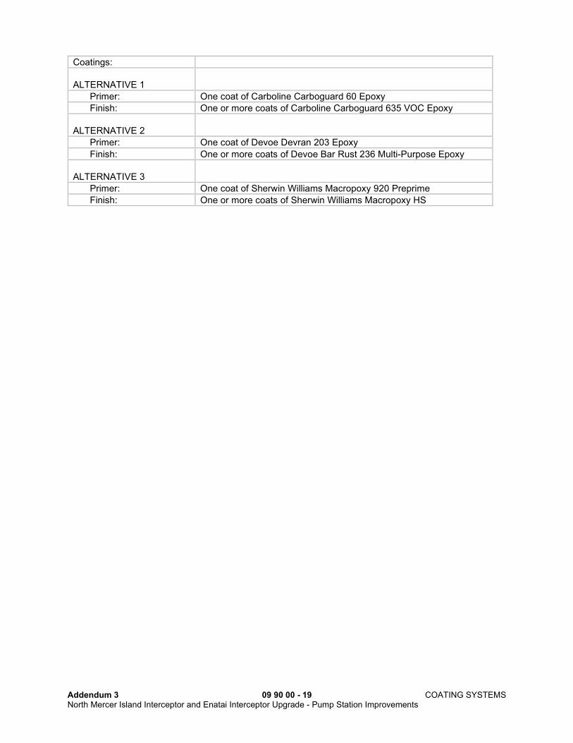
Coatings:
ALTERNATIVE 1
Primer: One coat of Carboline Carboguard 60 Epoxy
Finish: One or more coats of Carboline Carboguard 635 VOC Epoxy
ALTERNATIVE 2
Primer: One coat of Devoe Devran 203 Epoxy
Finish: One or more coats of Devoe Bar Rust 236 Multi-Purpose Epoxy
ALTERNATIVE 3
Primer: One coat of Sherwin Williams Macropoxy 920 Preprime
Finish: One or more coats of Sherwin Williams Macropoxy HS

Addendum 3 09 90 00 - 20 COATING SYSTEMS North Mercer Island Interceptor and Enatai Interceptor Upgrade - Pump Station Improvements
Coating System Identification:
B-3
Coating Material: Epoxy, 8 mils DFT nominal
Surfaces: Aluminum
Service Condition: Interior, exterior, where aluminum is in contact with concrete or dissimilar metals
Surface Preparation: Surface preparation for nonferrous and galvanized metal shall include a pressure wash with a cleaning solution recommended by the coating manufacturer, mixed with 160-degree water and applied at 2500 psi. Rinse with 160 degree water 2500 psi. When the surface is dry, prepare for coating application by providing a SSPC-SP 7. See Preparation paragraph within this Section for alternative methods.
Inspection Check points: Check points 1 through 9 apply.
Application: Shop or field.
Coatings:
ALTERNATIVE 1
Primer: One coat of Carboline Carboguard 60 Epoxy, 2 to 3 mils dry film.
Finish: One coat of Carboline Carboguard 635 VOC Epoxy, 4 to 6 mils dry film.
ALTERNATIVE 2
Primer: One coat of Devoe Devran 203 WB Epoxy, 2 to 3 mils dry film.
Finish: One coat of Devoe Bar Rust 236 Multi-Purpose Epoxy, 6 to 8 mils dry film thickness.

Addendum 3 09 90 00 - 21 COATING SYSTEMS North Mercer Island Interceptor and Enatai Interceptor Upgrade - Pump Station Improvements
Coating Systems Identification:
C-1
Coating Material: Epoxy primer, polyurethane finish
Surface: Metal
Service Condition: Non-immersed, exposure to moisture and sunlight, color required.
Surface Preparation:
Ferrous Metal: 1. Ferrous metal surfaces shall be prepared in accordance with SSPC-SP-10.
2. Shop primed surfaces which are to be incorporated in the work shall be prepared in the field by cleaning all surfaces in accordance with SSPC-SP 2. Damaged shop coated areas shall be cleaned in accordance with SSPC-SP 11 and recoated with the primer specified. Previously coated surfaces shall be feathered in at the edges.
Nonferrous and Galvanized Metal:
Alternative surface preparation methods shall be per the manufacturer’s written direction for profile and surface cleanliness for the given application.
Inspection Check Points: Check points 1, 2, 6, 7, and 10-12.
Application: Shop or field.
General: Drying time between coats shall be as specified by the manufacturer for the site conditions.
Inspection Check Points: Check points 3, 4, 5, 7, and 8.
System Thickness: 8 mils dry film minimum.
Level of Containment: Refer to 1.08.

Addendum 3 09 90 00 - 22 COATING SYSTEMS North Mercer Island Interceptor and Enatai Interceptor Upgrade - Pump Station Improvements
Coatings:
ALTERNATIVE 1
Primer: One coat of Carboline Carboguard 635 VOC Epoxy
Finish: One or more coats of Carboguard Carbothane 8845 Polyurethane
ALTERNATIVE 2
Primer: One coat of Devoe Devran 203 Epoxy
Finish: One or more coats of Devoe Devthane 379H Polyurethane
ALTERNATIVE 3
Primer: One coat of Sherwin Williams Macropoxy HS
Finish: One or more coats of Sherwin Williams Hi-Solids Polyurethane 250
Coating Systems Identification:
C-3
Coating Material: Vinyl Ester, 40-60 mils DFT nominal
Surfaces: Concrete, secondary containment: all vertical and horizontal surfaces within the containment area including the top of the containment wall. Concrete exposed to chemical leakage: Pipe trenches and equipment pads associated with conveying the chemicals listed below.
Service Condition: Chemicals stored in containment or conveyed are: sodium hydroxide (25% concentration), ferric chloride (35-40% concentration), sodium hypochlorite (15% concentration), citric acid (50% concentration), and both liquid and dry polymers (50% concentration). Exposure: splash-spill up to 48 hours
Surface Preparation: concrete and masonry
Allow new concrete and mortar to cure 28 days. Abrasive blast or mechanically abrade concrete to remove laitance, form release agents, curing compounds, hardeners, sealers, dirt, oil and other contaminants. Surfaces must be clean, dry and sound. Voids and cracks shall be repaired per Section 03 30 00. When repair work in Section 03 30 00 is complete, prepare concrete per SSPC-SP 13 to ICRI Technical Guideline #310.2. Following surface cleaning, apply a coat of the manufacturer’s recommended patching mortar to entire surface to repair bug holes and other imperfections.
Surface Preparation: metals
Metals shall be prepared to SSPC-SP 10 Near White Blast Cleaning.
Inspection Check Points: Check points 2, 6, 7, 10, and 11.
General: Follow manufacturer’s recommendation for crack repair and details at floor penetrations, wall bases, construction joints, equipment bolts, metal angle frames at trenches, transitions and terminations at edge of system, and other details specific to the structure being coated.
Application: 1. Patching mortar shall cure per manufacturer’s requirements prior to primer application.
2. Prime coat shall be thinned and applied as recommended by the coating manufacturer.
3. Drying time between coats shall be as recommended by coating manufacturer.
4. Extend coating completely under structures and equipment. 5. Provide continuous sealant, backing material, and joint-lining
treatment recommended by the coating manufacturer at all expansion, isolation, and construction joints.
6. Coat over equipment anchors and base plates installed in areas receiving coating to maintain continuous liquid-tight seal.
Inspection Check points: Check points 3-5, 7 and 8.
System Thickness: 40 mils dry film minimum, excluding patching mortar.
Addendum 3 09 90 00 - 23 COATING SYSTEMS North Mercer Island Interceptor and Enatai Interceptor Upgrade - Pump Station Improvements
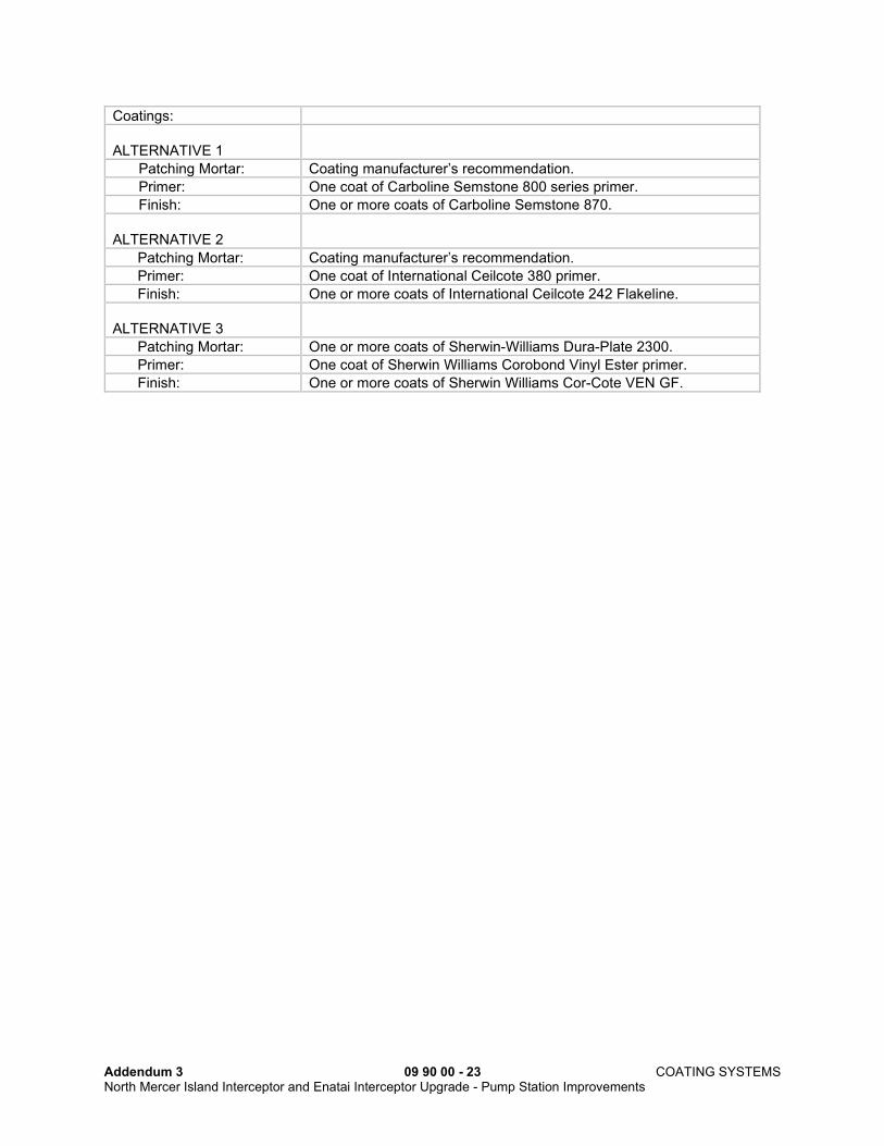
Coatings:
ALTERNATIVE 1
Patching Mortar: Coating manufacturer’s recommendation.
Primer: One coat of Carboline Semstone 800 series primer.
Finish: One or more coats of Carboline Semstone 870.
ALTERNATIVE 2
Patching Mortar: Coating manufacturer’s recommendation.
Primer: One coat of International Ceilcote 380 primer.
Finish: One or more coats of International Ceilcote 242 Flakeline.
ALTERNATIVE 3
Patching Mortar: One or more coats of Sherwin-Williams Dura-Plate 2300.
Primer: One coat of Sherwin Williams Corobond Vinyl Ester primer.
Finish: One or more coats of Sherwin Williams Cor-Cote VEN GF.
Addendum 3 09 90 00 - 24 COATING SYSTEMS North Mercer Island Interceptor and Enatai Interceptor Upgrade - Pump Station Improvements
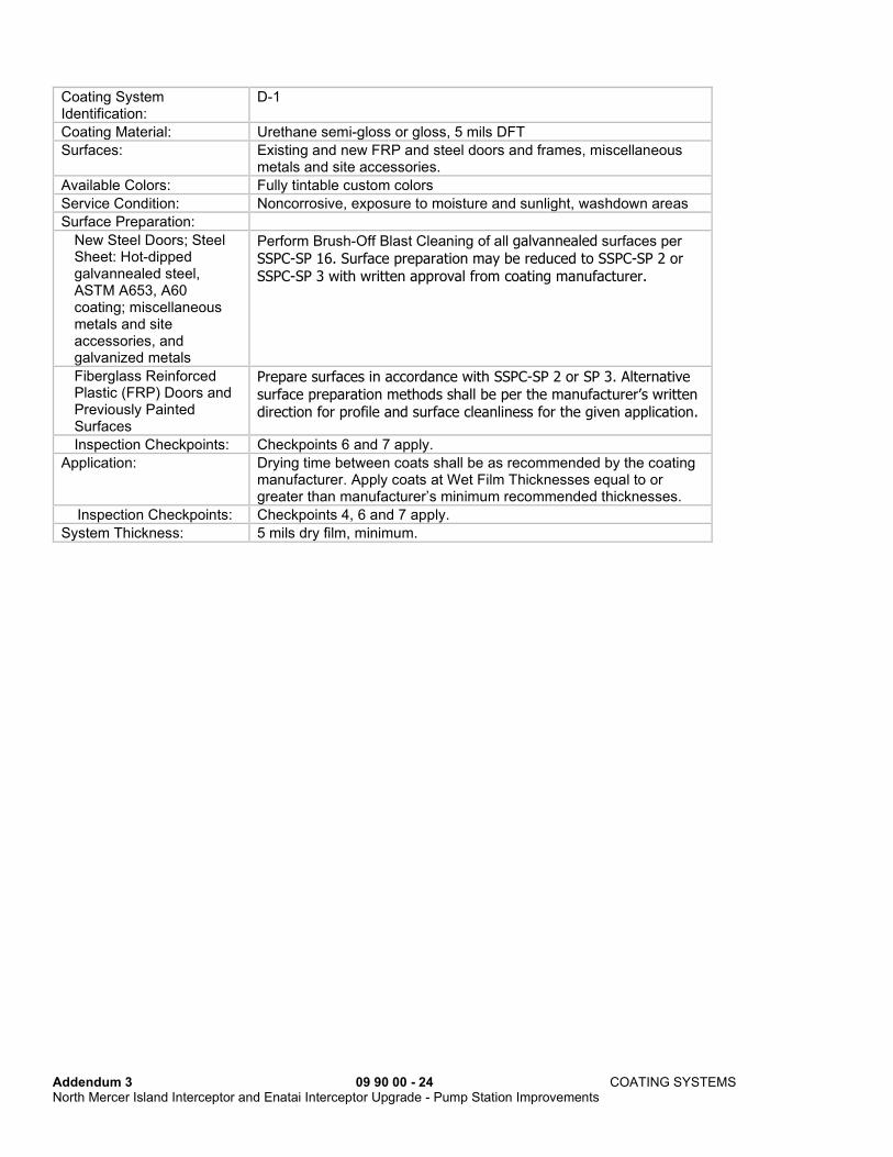
Coating System Identification:
D-1
Coating Material: Urethane semi-gloss or gloss, 5 mils DFT
Surfaces: Existing and new FRP and steel doors and frames, miscellaneous metals and site accessories.
Available Colors: Fully tintable custom colors
Service Condition: Noncorrosive, exposure to moisture and sunlight, washdown areas
Surface Preparation:
New Steel Doors; Steel Sheet: Hot-dipped galvannealed steel, ASTM A653, A60 coating; miscellaneous metals and site accessories, and galvanized metals
Perform Brush-Off Blast Cleaning of all galvannealed surfaces per
SSPC-SP 16. Surface preparation may be reduced to SSPC-SP 2 or
SSPC-SP 3 with written approval from coating manufacturer.
Fiberglass Reinforced Plastic (FRP) Doors and Previously Painted Surfaces
Prepare surfaces in accordance with SSPC-SP 2 or SP 3. Alternative
surface preparation methods shall be per the manufacturer’s written direction for profile and surface cleanliness for the given application.
Inspection Checkpoints: Checkpoints 6 and 7 apply.
Application: Drying time between coats shall be as recommended by the coating manufacturer. Apply coats at Wet Film Thicknesses equal to or greater than manufacturer’s minimum recommended thicknesses.
Inspection Checkpoints: Checkpoints 4, 6 and 7 apply.
System Thickness: 5 mils dry film, minimum.

Addendum 3 09 90 00 - 25 COATING SYSTEMS North Mercer Island Interceptor and Enatai Interceptor Upgrade - Pump Station Improvements
Coatings:
Sheen: SEMI-GLOSS or GLOSS
ALTERNATIVE 1
Primer: Hot-dipped galvannealed steel
One coat of Carboline Galoseal WB.
Primer: FRP and previously painted surfaces
One coat of Carboline Sanitile 120.
Finish: Two coats of Carbothane 134 HG.
ALTERNATIVE 2
Primer: Hot-dipped galvannealed steel, FRP, and previously painted surfaces
N/A
Finish: Two coats of PPG Durethane DTM 95-3300.
ALTERNATIVE 3
Primer: Hot-dipped galvannealed steel
One coat of Sherwin-Williams DTM Wash Primer.
Primer: FRP and previously painted surfaces
N/A
Finish: Two coats of Sherwin-Williams Acrolon 218HS Acrylic Polyurethane.
ALTERNATIVE 4
Approved Equal.

Addendum 3 09 90 00 - 26 COATING SYSTEMS North Mercer Island Interceptor and Enatai Interceptor Upgrade - Pump Station Improvements
Coating System Identification:
H-1
Coating Material: High temperature silicone, 1.5 mils DFT nominal
Surface: Metal
Service Condition: Temperature to 600 degrees F, continuous
Surface Preparation: Metal surfaces shall be prepared in accordance with SSPC-SP 10 (Near White Metal Blast Cleaning).
Inspection Check points: Check points 1 through 9 apply.
Application: 1. Field 2. Curing as required by coating manufacturer.
Coatings:
ALTERNATIVE 1 Three coats of International Intertherm 50
ALTERNATIVE 2
Two coats of Sherwin-Williams KEM HI-TEMP HEAT-FLEX II 450, Aluminum Color only

Addendum 3 09 90 00 - 27 COATING SYSTEMS North Mercer Island Interceptor and Enatai Interceptor Upgrade - Pump Station Improvements
Coating System Identification:
J-1
Coating Material: Clear acrylic urethane.
Surfaces: Exterior Exposed Concrete
Surface Preparation:
New Concrete: Concrete surfaces shall be allowed to age for at least 28 days and allowed to dry to the moisture content recommended by the coating manufacturer. Moisture content shall be tested by the Contractor and witnessed by the Project Representative in accordance with ASTM D4263, or approved equal. If the floor is trowel-finished the surface shall be etched with a non-acid etching chemical such as NewLook QuickEtch or Eco Safety Eco-Etch Pro and then cleaned by 2,500 psi minimum pressure wash. If the floor is broom-finished the surface shall be cleaned by 2,500 psi minimum pressure wash.
Existing Concrete: Previous coatings shall be removed with a “blastrac” and then cleaned by 2,500 psi minimum pressure wash. Voids and cracks shall be repaired.
Application: 1. Field. 2. Sealer or filler shall dry a minimum of 48 hours prior to
application of prime coat. 3. Prime coat shall be thinned and applied as recommended by the
coating manufacturer, provided the coating as applied complies with prevailing air pollution control regulations.
Inspection Check points: Checkpoints 6, 7, and 10 apply.
System Thickness: Two coats at 3 mils wet film each.
Coatings:
ALTERNATIVE 1
Two coats Rainguard Clear-Seal Low Gloss Acrylic Urethane Sealer
ALTERNATIVE 2
Two coats of Eagle Armor Seal

Addendum 3 09 90 00 - 28 COATING SYSTEMS North Mercer Island Interceptor and Enatai Interceptor Upgrade - Pump Station Improvements
Coating System Identification:
J-3
Coating Material: Water reducible epoxy, 5 mils DFT nominal
Surfaces: Concrete floors, interior.
Service Condition: Traffic area, some standing water.
Surface Preparation:
New Concrete: Concrete surfaces shall be allowed to age for at least 28 days and allowed to dry to the moisture content recommended by the coating manufacturer. Moisture content shall be tested by the Contractor and witnessed by the Project Representative in accordance with ASTM D4263, or approved equal. Loose concrete, form oils, surface hardeners, curing compounds and laitance shall be removed. Surface shall be cleaned by steam cleaning and abraded with a “blastrac”. Voids and cracks shall be repaired.
Existing Concrete: Loose concrete, form oils, surface hardeners, curing compounds and laitance shall be removed. Surface shall be cleaned by steam cleaning and abraded with a “blastrac”. Voids and cracks shall be repaired.
Application: Field.
General: Follow manufacturer's instructions for mixing and "sweat-in" time.
Inspection Check points: Checkpoints 6, 7, and 10 apply.
System Thickness: Two coats at 5 mils wet film each.
Color: As selected by Project Representative from manufacturer’s standard colors.
Coatings:
ALTERNATIVE 1
Two coats of International 4426/4428 TruGlaze WB Epoxy or Two coats of PPG Aquapon WB epoxy
ALTERNATIVE 2
Two coats of Carboline Sanitile 555
ALTERNATIVE 3
Two coats of Rust-Oleum Sierra S40 Epoxy

Addendum 3 09 90 00 - 29 COATING SYSTEMS North Mercer Island Interceptor and Enatai Interceptor Upgrade - Pump Station Improvements
Coating System Identification:
J-5
Coating Material: Silane water repellent clear sealer.
Surfaces: Unpainted CMU and Concrete
Service Condition: Non-corrosive environment.
Surface Preparation:
New Concrete and Masonry:
Concrete surfaces shall be allowed to age for at least 28 days and allowed to dry to the moisture content recommended by the coating manufacturer. Pressure wash or solvent wipe to ensure that surfaces are free from laitance, dust, paint, grease, and oil.
Existing Concrete and Masonry:
Loose concrete, form oils, surface hardeners, curing compounds and laitance shall be removed. Surface shall be cleaned by pressure washing. Voids and cracks shall be repaired.
Application: Field.
General: Follow manufacturer's instructions.
Inspection Check points: Checkpoints 6, 7, and 10 apply.
System Thickness: Coat to surface saturation.
Color: Clear.
Coatings:
ALTERNATIVE 1
One coat of BASF MasterProtect H 1000
ALTERNATIVE 2
One coat of OKON S-20

Addendum 3 09 90 00 - 30 COATING SYSTEMS North Mercer Island Interceptor and Enatai Interceptor Upgrade - Pump Station Improvements
Coating System Identification:
J-6
Coating Material: Anti-Graffiti Coating
Surfaces: Exterior masonry and vertical concrete
Service Condition: Non-corrosive environment.
Surface Preparation:
New Concrete and Masonry:
Concrete surfaces shall be allowed to age for at least 28 days and allowed to dry to the moisture content recommended by the coating manufacturer. Pressure wash or solvent wipe to ensure that surfaces are free from laitance, dust, paint, grease, and oil.
Existing Concrete and Masonry:
Loose concrete, form oils, surface hardeners, curing compounds and laitance shall be removed. Surface shall be cleaned by pressure washing. Voids and cracks shall be repaired.
Doors and door frames: Clean by solvent wiping.
Application: Field.
General: Follow manufacturer's instructions.
Inspection Check points: Checkpoints 6, 7, and 10 apply.
System Thickness: Coat to surface saturation.
Color: Clear.
Coatings:
ALTERNATIVE 1
One coat of OKON Graffiti Barrier Coat
ALTERNATIVE 2
One coat of Rainguard Vandlguard One
Addendum 3 09 90 00 - 31 COATING SYSTEMS North Mercer Island Interceptor and Enatai Interceptor Upgrade - Pump Station Improvements
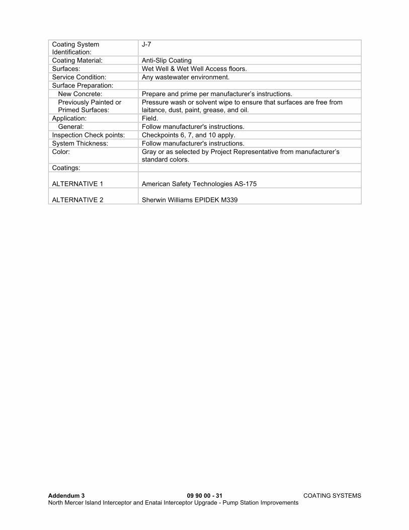
Coating System Identification:
J-7
Coating Material: Anti-Slip Coating
Surfaces: Wet Well & Wet Well Access floors.
Service Condition: Any wastewater environment.
Surface Preparation:
New Concrete: Prepare and prime per manufacturer’s instructions.
Previously Painted or Primed Surfaces:
Pressure wash or solvent wipe to ensure that surfaces are free from laitance, dust, paint, grease, and oil.
Application: Field.
General: Follow manufacturer's instructions.
Inspection Check points: Checkpoints 6, 7, and 10 apply.
System Thickness: Follow manufacturer's instructions.
Color: Gray or as selected by Project Representative from manufacturer’s standard colors.
Coatings:
ALTERNATIVE 1
American Safety Technologies AS-175
ALTERNATIVE 2
Sherwin Williams EPIDEK M339

Addendum 3 09 90 00 - 32 COATING SYSTEMS North Mercer Island Interceptor and Enatai Interceptor Upgrade - Pump Station Improvements
Coating System Identification:
L-1a
Coating Material: 100% Acrylic semi-gloss or eggshell/satin, 4.5 mils DFT nominal
Surfaces: Concrete, masonry, plaster, gypsum board, metals, and previously painted surfaces.
Surface Preparation:
Concrete and Masonry: Concrete surfaces shall be allowed to age for at least 28 days and allowed to dry to the moisture content recommended by the coating manufacturer. Moisture content shall be tested by the Contractor and witnessed by the Project Representative per ASTM D4263, or approved equal. Loose concrete, form oils, surface hardeners, curing compounds, and laitance shall be removed from surfaces by grinding and chipping, and voids and cracks shall be repaired. Muriatic acid shall not be used. After cleaning, masonry surfaces shall be cleaned and filled with block filler compatible with the specified primer.
Previously painted surfaces:
Clean using a 3,000 PSI, 2.8 GPM minimum, 110F minimum (130F maximum) hot water pressure washer using a new 15 degree or 25
degree fan tip held at 12” or less from the surface. The pressure
washing nozzle orifice size shall be selected from industry standard nozzle charts for the rated flow and pressure of the pump. Use a
phosphate-free biodegradable cleaner in the wash water such as Simple Green House & Siding Cleaner Pressure Washer Concentrate,
Hotsy Enviro-Clean, or Krud Kutter House & Siding Pressure Washer Concentrate. Follow the additional requirements of ASTM D 4258
Detergent Water Cleaning. Hard to reach areas and all areas where
pressure washing will cause damage shall be cleaned using a solvent wipe or scrubbing with a firm bristle deck brush using 110F minimum
wash water mixed with a biodegradable cleaner listed in L-1a for “Previously painted surfaces”. Rinse with potable water after
pressure washing or scrubbing.
Plaster: Plaster surfaces shall be dry and clean and free from grit, loose plaster and surface irregularities. Cracks and holes shall be repaired with acceptable patching materials, keyed to existing surfaces, and sanded smooth. Surfaces shall be cleaned with clean water by washing and scrubbing to remove foreign substances. After cleaning, surfaces shall be sealed with a compatible sealer.
Gypsum Wallboard: Tape joints and spackled nail heads shall be sanded smooth and dusted. Seal with PVA sealer.
Inspection Checkpoints: Checkpoints 6, 7, 11, and 12 apply.
Application: Sealer or filler shall cure according to manufacturer’s recommendations prior to priming. Drying time between coats shall be as recommended by the coating manufacturer. Apply coats at Wet Film Thicknesses equal to or greater than manufacturer’s minimum recommended thicknesses.
Inspection Checkpoints: Checkpoints 6 and 7 apply.
System Thickness: 4.5 mils dry film, minimum, for 1 prime coat and 2 topcoats.

Addendum 3 09 90 00 - 33 COATING SYSTEMS North Mercer Island Interceptor and Enatai Interceptor Upgrade - Pump Station Improvements
Coatings:
Sheen: SEMI-GLOSS
ALTERNATE 1
Primer: Concrete, Metals, and previously painted surfaces
One coat of PPG-Glidden Hydrosealer Primer 6001.
Finish: Two coats of PPG-Devoe Devflex 4216HP.
ALTERNATE 2
Primer: Concrete and previously painted surfaces
One coat of Sherwin-Williams Loxon Concrete & Masonry Primer #A24W8300.
Primer: Metals One coat of Sherwin-Williams DTM Acrylic Primer #B66W1.
Finish: Two coats of Sherwin-Williams Sher-Cryl HPA Acrylic #B66-350.
Sheen: EGGSHELL/SATIN
ALTERNATE 1
Primer: Concrete, Metals, and previously painted surfaces
One coat of PPG-Glidden Hydrosealer Primer 6001.
Finish: Two coats of PPG Pitt-Tech Plus 90-1110.
ALTERNATE 2
Primer: Concrete and previously painted surfaces
One coat of Sherwin-Williams Loxon Concrete & Masonry Primer #A24W8300 tinted to near-topcoat color if possible.
Primer: Metals One coat of Sherwin-Williams DTM Acrylic Primer #B66W1.
Finish: Two coats of Sherwin-Williams Pro Industrial Acrylic #B66-660.
Coating System Identification:
P-1
Coating Material: Ceramic or glass reinforced epoxy lining for ductile iron pipe in wastewater service, 40 mils nominal DFT, 84% solids (minimum)
Surfaces: Ductile Iron Pipe
Available Colors: Green, White, or Black
Service Condition: Immersed, highly corrosive environment.
Surface Preparation:
Ductile Iron Pipe: The interior surfaces of Ductile Iron Pipe shall be prepared in accordance with NAPF 500-03-04.
Inspection Check Points: Ambient Conditions: Check point 7 Anchor Profile: Check point 2 or as specified by coating manufacturer
Application: Shop or field.
General: Drying time between coats shall be specified by the manufacturer for the site conditions.
Inspection Check Points: Ambient Conditions: Check point 7 DFT readings: Check point 4 or as specified by coating manufacturer Holiday testing: Check point 5 or as specified by coating manufacturer
Touch-Up: As specified by coating manufacturer

Addendum 3 09 90 00 - 34 COATING SYSTEMS North Mercer Island Interceptor and Enatai Interceptor Upgrade - Pump Station Improvements
Bells and Sockets: Apply coating as required by manufacturer to facilitate gasket fit.
System Thickness: 40 mils dry film (nominal), 35 mils dry film (minimum), 50 mils dry film (maximum).
Coatings:
ALTERNATIVE 1
One or more coats of Induron Protecto 401 Epoxy
ALTERNATIVE 2
One or more coats of Tnemec 431 Epoxy
ALTERNATIVE 3
One or more coats of Sherwin-Williams Dura-Plate 6000 Epoxy
END OF SECTION
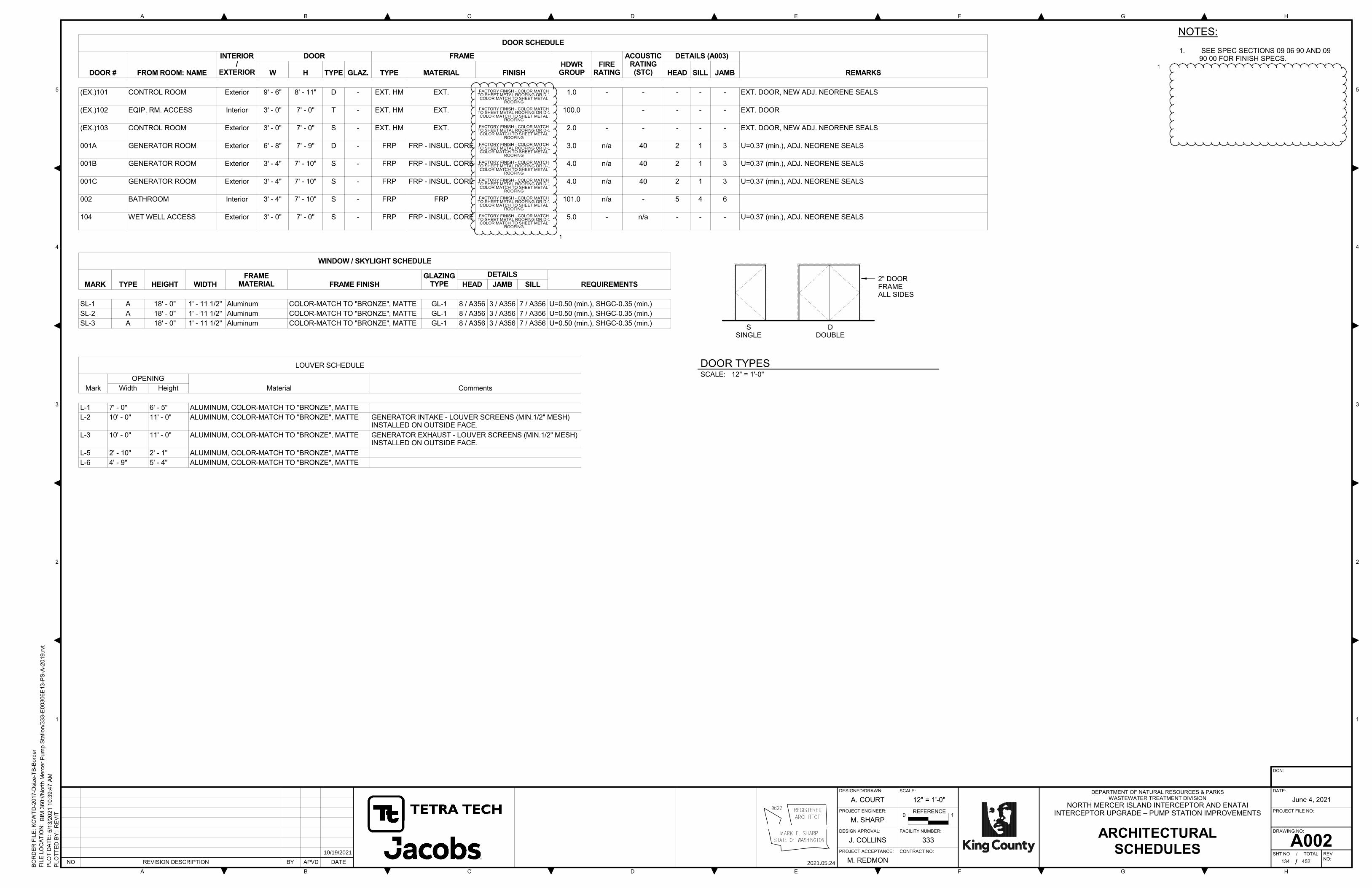
SSINGLE
DDOUBLE
2" DOOR FRAME ALL SIDES
1. SEE SPEC SECTIONS 09 06 90 AND 09 90 00 FOR FINISH SPECS.
NOTES:
®
NO REVISION DESCRIPTION BY APVD DATE
DESIGNED/DRAWN:
PROJECT ENGINEER:
DESIGN APROVAL:
PROJECT ACCEPTANCE: CONTRACT NO:
FACILITY NUMBER:
SCALE:
A B C D E F G H
A B C D E F G H
1
2
3
4
5
1
2
3
4
5
REFERENCE0 1
DCN:
DATE:
PROJECT FILE NO:
DRAWING NO:
SHT NO / TOTAL REV NO:
DEPARTMENT OF NATURAL RESOURCES & PARKS WASTEWATER TREATMENT DIVISION
/
PLO
TT
ED
BY
: R
EV
IT
PLO
T D
AT
E:
FIL
E L
OC
AT
ION
:
BO
RD
ER
FIL
E:
KC
WT
D-2
017-D
siz
e-T
B-B
ord
er
12" = 1'-0"
5/1
3/2
021 1
0:3
9:4
7 A
M
BIM
360
://N
ort
h M
erc
er
Pum
p S
tation
/ 333-E
00306E
13
-PS
-A-2
019
.rvt
A002
A. COURT
M. SHARP
J. COLLINS
M. REDMON
333ARCHITECTURAL
SCHEDULES
NORTH MERCER ISLAND INTERCEPTOR AND ENATAIINTERCEPTOR UPGRADE – PUMP STATION IMPROVEMENTS
DOOR SCHEDULE
DOOR # FROM ROOM: NAME
INTERIOR/
EXTERIOR
DOOR FRAMEHDWRGROUP
FIRERATING
ACOUSTICRATING(STC)
DETAILS (A003)
REMARKSW H TYPE GLAZ. TYPE MATERIAL FINISH HEAD SILL JAMB
(EX.)101 CONTROL ROOM Exterior 9' - 6" 8' - 11" D - EXT. HM EXT. C-1 - COLOR MATCHTO "BRONZE"
1.0 - - - - - EXT. DOOR, NEW ADJ. NEORENE SEALS
(EX.)102 EQIP. RM. ACCESS Interior 3' - 0" 7' - 0" T - EXT. HM EXT. C-1 - COLOR MATCHTO "BRONZE"
100.0 - - - - EXT. DOOR
(EX.)103 CONTROL ROOM Exterior 3' - 0" 7' - 0" S - EXT. HM EXT. C-1 - COLOR MATCHTO "BRONZE"
2.0 - - - - - EXT. DOOR, NEW ADJ. NEORENE SEALS
001A GENERATOR ROOM Exterior 6' - 8" 7' - 9" D - FRP FRP - INSUL. CORE FACTORY FINISH-"BRONZE"
3.0 n/a 40 2 1 3 U=0.37 (min.), ADJ. NEORENE SEALS
001B GENERATOR ROOM Exterior 3' - 4" 7' - 10" S - FRP FRP - INSUL. CORE FACTORY FINISH-"BRONZE"
4.0 n/a 40 2 1 3 U=0.37 (min.), ADJ. NEORENE SEALS
001C GENERATOR ROOM Exterior 3' - 4" 7' - 10" S - FRP FRP - INSUL. CORE FACTORY FINISH-"BRONZE"
4.0 n/a 40 2 1 3 U=0.37 (min.), ADJ. NEORENE SEALS
002 BATHROOM Interior 3' - 4" 7' - 10" S - FRP FRP FACTORY FINISH-"BRONZE"
101.0 n/a - 5 4 6
104 WET WELL ACCESS Exterior 3' - 0" 7' - 0" S - FRP FRP - INSUL. CORE FACTORY FINISH-"BRONZE"
5.0 - n/a - - - U=0.37 (min.), ADJ. NEORENE SEALS
WINDOW / SKYLIGHT SCHEDULE
MARK TYPE HEIGHT WIDTHFRAME
MATERIAL FRAME FINISHGLAZING
TYPE
DETAILS
REQUIREMENTSHEAD JAMB SILL
SL-1 A 18' - 0" 1' - 11 1/2" Aluminum COLOR-MATCH TO "BRONZE", MATTE GL-1 8 / A356 3 / A356 7 / A356 U=0.50 (min.), SHGC-0.35 (min.)
SL-2 A 18' - 0" 1' - 11 1/2" Aluminum COLOR-MATCH TO "BRONZE", MATTE GL-1 8 / A356 3 / A356 7 / A356 U=0.50 (min.), SHGC-0.35 (min.)
SL-3 A 18' - 0" 1' - 11 1/2" Aluminum COLOR-MATCH TO "BRONZE", MATTE GL-1 8 / A356 3 / A356 7 / A356 U=0.50 (min.), SHGC-0.35 (min.)
LOUVER SCHEDULE
Mark
OPENING
Material CommentsWidth Height
L-1 7' - 0" 6' - 5" ALUMINUM, COLOR-MATCH TO "BRONZE", MATTE
L-2 10' - 0" 11' - 0" ALUMINUM, COLOR-MATCH TO "BRONZE", MATTE GENERATOR INTAKE - LOUVER SCREENS (MIN.1/2" MESH)INSTALLED ON OUTSIDE FACE.
L-3 10' - 0" 11' - 0" ALUMINUM, COLOR-MATCH TO "BRONZE", MATTE GENERATOR EXHAUST - LOUVER SCREENS (MIN.1/2" MESH)INSTALLED ON OUTSIDE FACE.
L-5 2' - 10" 2' - 1" ALUMINUM, COLOR-MATCH TO "BRONZE", MATTE
L-6 4' - 9" 5' - 4" ALUMINUM, COLOR-MATCH TO "BRONZE", MATTE
SCALE: 12" = 1'-0"
DOOR TYPES
2021.05.24
ADDENDUM NO. 3 AC MFS
/ 452134
June 4, 2021
10/19/2021
1
1
FACTORY FINISH - COLOR MATCHTO SHEET METAL ROOFING OR D-1COLOR MATCH TO SHEET METAL
ROOFING
FACTORY FINISH - COLOR MATCHTO SHEET METAL ROOFING OR D-1COLOR MATCH TO SHEET METAL
ROOFING
FACTORY FINISH - COLOR MATCHTO SHEET METAL ROOFING OR D-1COLOR MATCH TO SHEET METAL
ROOFING
FACTORY FINISH - COLOR MATCHTO SHEET METAL ROOFING OR D-1COLOR MATCH TO SHEET METAL
ROOFING
FACTORY FINISH - COLOR MATCHTO SHEET METAL ROOFING OR D-1COLOR MATCH TO SHEET METAL
ROOFING
FACTORY FINISH - COLOR MATCHTO SHEET METAL ROOFING OR D-1COLOR MATCH TO SHEET METAL
ROOFING
FACTORY FINISH - COLOR MATCHTO SHEET METAL ROOFING OR D-1COLOR MATCH TO SHEET METAL
ROOFING
FACTORY FINISH - COLOR MATCHTO SHEET METAL ROOFING OR D-1COLOR MATCH TO SHEET METAL
ROOFING
1

NO REVISION DESCRIPTION BY APVD DATE
DESIGNED/DRAWN:
PROJECT ENGINEER:
DESIGN APROVAL:
PROJECT ACCEPTANCE: CONTRACT NO:
FACILITY NUMBER:
SCALE:
A B C D E F G H
A B C D E F G H
1
2
3
4
5
1
2
3
4
5
REFERENCE0 1
DCN:
DATE:
PROJECT FILE NO:
DRAWING NO:
SHT NO / TOTAL REV NO:
DEPARTMENT OF NATURAL RESOURCES & PARKS WASTEWATER TREATMENT DIVISION
/
PLO
TT
ED
BY
: R
EV
IT
PLO
T D
AT
E:
FIL
E L
OC
AT
ION
:
BO
RD
ER
FIL
E:
KC
WT
D-2
017-D
siz
e-T
B-B
ord
er
NTS
10/2
2/2
021 1
2:0
6:0
2 P
M
BIM
360://N
ort
h M
erc
er
Pu
mp
Sta
tio
n/ 3
33
-E0
03
06E
13
-PS
-D-2
019
.rvt
M001
M. HUXLEY
M. HUXLEY
J. COLLINS
M. REDMON
MECHANICAL PIPING
SYMBOLS
NORTH MERCER ISLAND INTERCEPTOR AND ENATAIINTERCEPTOR UPGRADE - PUMP STATION IMPROVEMENTS
JUNE 4, 2021
1 Revision 3 GMS LER 10/22/21
3

▲▲ ▲ ▲ ▲ ▲ ▲cA B D E F G H
5 5PROTECT EXISTING IRRIGATION CONTROL BOXES
PROTECT FRUITLAND LANDING SIGN
2INSTALL 50' LONG (MIN) CONSTRUCTION ENTRANCE VC015
APROTECT EXISTING VEGETATION, IF POSSIBLE (APPROX LOCATION, NOT SURVEYED)
EXIST CONCRETE WALL t.Q
FRUITLAND LANDING PARK CONSTRUCTION LIMITS4 1◄ ►
>-<
6 >-.QEXIST POWER POLE <o <>CZ LUO >- m ss
___dS- dS- \\ CO‘AHdS- dS- CZ.QdS- dS------ Odb'— V. O}dS- dS- dS- QCDdS13on oco -3on STRUCTURE SETTLEMENT POINT (TYP OF 4)
ascz3r o□CO asiSSP 3onK2 o4 43on as as1 '=^1 3A0 as as3A0 as£3\C'q_-ss ss S' - a*\o CO8y JSP^s as —P 3/tfpss 3A0SS 3A0mGoiy(TYP)V
SS 3Ai< =JAQco 3AQAJ\ \ 3AQsQ
3, 3A0SS co\QOGz! J/t JA, )SsSITdS- uisrr3 SSP or LUSs brVorVop HVHdSV:on orsss ss LUSS( 3} 97TH AVE SEssh SS 5^ ;s- c/>SHORELINE : ,
LAKE WASHINGTON /lwco f wCO /
SS ss- SS noSSlAld-SS- 0 SSlAlz-S1 10940 M s,SSIAI3-S& SS SS SSi SS^lTTJS1 & - 3: -!/ ______ -HIVd cddAVdO £a - IAId SS ------LAId SfSOA/c - IAId SSco -IAId SSxyO,□ -IAId SSSSP S'e-^ L kPC -IAId SS■Q6-7 is ZD©◄ ►dS
-©—|24314b\^pZy^CYZL as\o ss ss ss10935 ss ss( ss ss3C5 ssco fG3A 'S La as a as CDas/09 hhh+H^f'as' asSSP L < as
\as GAOS KJrhhh^ asCO f®£f/d-Hd4L
CO Q/Hd-H-f-A a& n >S
•c,(
COD-d-B YSD ;SD St*SD SD SD SD Ias v .
. \
ZD
\(as dS-■
dS- UdS- ■JQ—X <LdS-
e-\ . I O------^dS— dS- d dS-
O-^-o IdAVdOO- ©—ft ¥Q- ~773 \ IO ©2431524316 ** * * *V.\ >-SSP0I <I3 34' x 10' CIPP INSTALLATION RECEIVING PIT. PROTECT EXISTING SEWER PIPES IN PLACE-----------------------------------
4>1 INSTALL FILTER FABRIC FENCE AT CONSTRUCTION LIMITS--------------
EXIST METAL RAIL FENCE >TREE LOD, TYPC012 CZ cro 4TREE PROTECTION FENCING, TYP
r-C012 XI rom
TREE INVENTORY TABLE:NOTES:◄ ►
LOD (ft.) DBH (in.)SCIENTIFIC NAME COMMON NAME DISPOSITION EXCEPTIONAL PROTECTION NOTESTREE IDSEE TREE MANAGEMENT SPECIFICATIONS FOR TREE PROTECTION REQUIREMENTS WHEN WORKING WITHIN THE LOD (LIMITS OF DISTURBANCE).
7.FRUITLAND LANDING PARK TO BE CLOSED FOR THE DURATION OF CONSTRUCTION.1.FENCING, ARBORIST, AND GROUND PROTECTION IF EXPOSED
ACER PALMATUM JAPANESE MAPLE NO24316 4 6.7 PROTECTFOR TESC GENERAL NOTES, SEE DRAWING C011.2.TREE HEALTH SHALL BE MONITORED BY THE PROJECT ARBORIST DURING AND AFTER CONSTRUCTION, UNTIL SUBSTANTIAL COMPLETION AS STATED IN THE TREE MANAGEMENT SPECIFICATIONS.
8.FENCING, ARBORIST, AND GROUND PROTECTION IF EXPOSED
3. CONTRACTOR SHALL BE RESPONSIBLE FOR DEWATERING AND IMPLEMENTING AN APPROPRIATE PLAN FOR EXCAVATIONS. PLAN SHALL BE IN ACCORDANCE WITH APPLICABLE GEOTECHNICAL RECOMMENDATIONS FOR THE SITE. CONTRACTOR SHALL DISCHARGE PUMPED GROUNDWATER IN SUCH A MANNER THAT ALL SEDIMENT IS CONTAINED WITHIN THE PROJECT LIMITS. ALL DEWATERING EFFLUENT SHALL BE DISCHARGED WITHIN AN EXISTING NATURAL DRAINAGE COURSE OR TO AN EXISTING STORM DRAIN (OR POTENTIALLY THE NEW WET WELL) AND SHALL MEET CURRENT WATER QUALITY STANDARDS FOR SAID DISCHARGES. REFER TO DEWATERING SPECIFICATION. CONTRACTOR SHALL APPLY FOR AND OBTAIN ANY ADDITIONAL REQUIRED PERMIT(S) TO PERFORM THIS WORK.
PRUNUS EMARGINATA BITTER CHERRY NO24315 8.2 PROTECT5
FENCING, ARBORIST, AND GROUND PROTECTION IF EXPOSED
24314 ACER PALMATUM JAPANESE MAPLE 6 9.5 PROTECT NO
<X> KEY NOTES:2 2FENCING, ARBORIST, AND GROUND PROTECTION IF EXPOSED
10935 PSEUDOTSUGA MENZIESII DOUGLAS FIR 13 19.3 PROTECT NO
CITY WILL REMOVE EXISTING PICNIC TABLE PRIOR TO CONSTRUCTION. CONTRACTOR SHALL REMOVE AND RECYCLE EXISTING CONCRETE SLAB.
1. FENCING, ARBORIST, AND GROUND PROTECTION IF EXPOSED
10940 KOELREUTERIA PANICULATA GOLDEN RAINTREE 12 17.3 PROTECT NO
REMOVE, PROTECT, AND DELIVER TO CITY EXISTING FLAGSTONES BETWEEN BENCH SLAB AND PICNIC TABLE SLAB.
2.
ALL EXCAVATION WORK SHALL BE DONE IN SUCH A MANNER AS TO NOT IMPACT PROPERTY AND STRUCTURES OUTSIDE THE PARK PROPERTY OR RIGHT-OF-WAY. CONTRACTOR SHALL BE RESPONSIBLE FOR ANY TEMPORARY SHORING THAT MAY BE REQUIRED FOR THE EXCAVATION. CONTRACTOR SHALL SUBMIT NECESSARY PLANS AND CALCULATIONS COMPLETED BY A PROFESSIONAL ENGINEER LICENSED IN THE STATE OF WASHINGTON. CONTRACTOR SHALL BE COMPLETELY RESPONSIBLE FOR ALL SITE SAFETY, INCLUDING PROPER EXCAVATION AND SHORING METHODS, AND PROTECTION OF ADJACENT PROPERTIES. EXCAVATION AND BACKFILL SHALL BE IN ACCORDANCE WITH APPLICABLE RECOMMENDATIONS CONTAINED IN THE GEOTECHNICAL REPORT FOR THE SITE.
4.3. CITY WILL TEMPORARILY REMOVE EXISTING PARK BENCH TO A SECURE STORAGE
AREA PRIOR TO CONSTRUCTION. DEMOLISH EXISTING CONCRETE SLAB.◄ ►CD£ CONTRACTOR SHALL LOCK THE GATE FOR CONTRACT DURATION.4.■O
CMOCDO VEGETATION EXTENT (NOT TREES) BEYOND THE TREE PROTECTION FENCING EXTENT
SHOWN IS TO BE TRIMMED PRIOR TO FENCING PLACEMENT.5.
C/3
CO
AFTER EXISTING GENERATOR SET NO LONGER NEEDED, TEMPORARY SEDIMENTATION TANK COULD POTENTIALLY BE PLACED ABOVE THE VAULTS IN THIS LOCATION.
6.LUCDOCOO
CONTRACTOR SHALL PROVIDE ALL DEWATERING ACTIVITIES ASSOCIATED WITH REMOVING ANY ADDITIONAL WATER WHICH ENTERS EXCAVATIONS THROUGH AND/OR RESULTING FROM THE EXISTING FORCE MAIN REHABILITATION, INSTALLATION OF THE NEW FORCE MAIN, AND TRENCHES UPSTREAM OF THE EXCAVATION. CONTRACTOR SHALL BE RESPONSIBLE FOR MANAGING WATER AND LIMITING DISCHARGE TO DOWNSTREAM EXCAVATIONS.
5.oLU 1
PROTECT CONCRETE SLAB AND GENERATOR SET (TO BE INSTALLED BY CITY PRIOR TO THIS CONTRACT).
7.CD t- ■p C/3 O d
CD _lm >>7 OCD CM N O CO [b9 QCM □5 6^ o ^a o a.I— ■<—> o CO
o ° ^ o 34 ^d >< «« CO CM .gO A CM < LU Z O Q LJJ O zj E !< w CDC4 O c g ID O Q l a —1 (— P £ w ° ° O d _l _lCD IL CL D.
8. CONTRACTOR SHALL EXPOSE THE TWO CORNERS OF THE EXISTING STATION TO INSTALL AND MONITOR THE STRUCTURE SETTLEMENT POINTS. 0 10 20 30
DCN:SEE SHEET C608 AND 609 FOR ADDITIONAL TREES TO PROTECT.6.
SCALE IN FEETDESIGNED/DRAWN: SCALE: DATE:DEPARTMENT OF NATURAL RESOURCES & PARKS
WASTEWATER TREATMENT DIVISION
NORTH MERCER ISLAND INTERCEPTOR AND ENATAI INTERCEPTOR UPGRADE - PUMP STATION IMPROVEMENTS
June 4, 2021E. BRODAHL NTS03CO mTETRA TECHIt PROJECT FILE NO:PROJECT ENGINEER: REFERENCE0 r,E. BRODAHL
■z. LIFT STATION 11
TESC PLAN AND NOTES' DESIGN APPROVAL: FACILITY NUMBER: DRAWING NO:
C602J. COLLINS N/A King CountyJacobsA PROJECT ACCEPTANCE: CONTRACT NO:IDD JUC 10/20/2021ADDENDUM NO. 3 SHT NO / TOTAL 429 / 452
REVNO:M. REDMONREVISION DESCRIPTION 2021.10.20NO BY APVD DATE
TT T T T TDC E G HA B